Network Management System Industrial HiVision 8.2. User Manual (2021) - page 13
References
Preferences > Advanced > Export to InfluxDB®
Preferences > Advanced > Export to InfluxDB®
Export to InfluxDB®
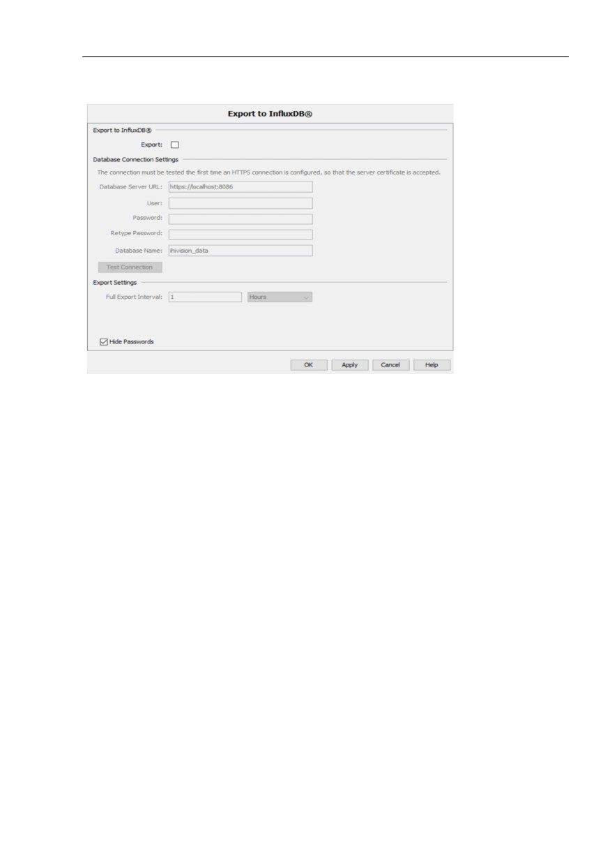
The “Export to InfluxDB®“ dialog lets you enable or disable the export to
InfluxDB®, and configure the connection parameters and the export
settings. To configure these parameters, perform the following steps:
To enable the “Export to InfluxDB®“ function, mark the “Export“
checkbox. When you mark this checkbox, the fields related to the
connection parameters become editable.
Default setting: unmarked
In the “Database Server URL“ field, enter the URL for the InfluxDB®
server.
Possible values: ASCII character string with 1..1000 characters
Default setting: https://localhost:8086
In the “User“ field, enter the user name of the InfluxDB® database.
Possible values: ASCII character string with 1..40 characters
Default setting: empty field
In the “Password“ and the “Retype Password“ fields, enter the same
password for the InfluxDB® database.
Possible values: ASCII character string with 1..40 characters
Default setting: empty field
To test the connection with the InfluxDB® server, click the “Test
Connection“ button.
When you click the “Test Connection“ button, a connection testing
procedure is triggered. In order for the connection testing procedure to
start, fill each field in the “Database Connection Settings“ frame.
The connection testing procedure consists of the following verification
flow:
The procedure checks that an InfluxDB® server is up and running
at the URL configured in the “Database Server URL“ field.
If you use the HTTPS protocol, then the connection testing
procedure prompts you to accept InfluxDB® server certificates.
The procedure accepts the login to the InfluxDB® server with the
configured credentials.
380
References
Preferences > Advanced > Export to InfluxDB®
The procedure checks that the user identified by these credentials
has write permissions to the InfluxDB® database.
If the database does not exist, then the procedure creates the
InfluxDB® database.
When the connection testing procedure ends, Industrial HiVision
displays a status icon and an explanation message in the field related
to the “Test Connection“ button.
When the connection is established, Industrial HiVision displays a
green check mark.
If the connection is not established, then you get one of the following
error messages:
“Server not reachable“
There is no server running at the specified URL.
Verify that the InfluxDB® server is up or that the specified URL is
correct.
“Wrong protocol“
The InfluxDB® server accepts an HTTP protocol but the URL
specifies an HTTPS protocol or the other way around.
Verify that the URL you provided in the “Database Server URL“
field contains the correct transfer protocol.
“Authentication failed“
The provided credentials are incorrect.
Verify that you provided the correct credentials.
“No write permissions“
The provided credentials identify a user that does not have write
permissions to the InfluxDB® database.
Verify that the user you provided has write permissions to the
InfluxDB® database.
381
References
Preferences > Advanced > Export to InfluxDB®
“Operation failed“
The HTTPS certificate was not accepted in the “Confirm Server
Certificate for Industrial HiVision Server“ dialog or an internal error
occurred.
Accept the correct InfluxDB® server certificate in the “Confirm
Server Certificate for Industrial HiVision Server“ dialog.
“Operation in progress“
The connection testing operation is currently in progress.
Wait for the connection testing procedure to complete.
When you use the secure HTTPS protocol and test the connection to
an InfluxDB® server for the first time, the “Confirm Server Certificate
for Industrial HiVision Server“ dialog opens. This dialog prompts you
to confirm the InfluxDB® server certificate.
To accept the certificate, click the “Accept“ button.
If you do not test the connection and click the “Apply“ button, then
Industrial HiVision displays the following warning:
“After configuring a https transport testing connection is mandatory
to accept server certificate“
If you close the “Preferences“ dialog without testing the connection,
then the export to InfluxDB® server is not enabled.
In the “Full Export Interval“ field, enter the time interval at which
Industrial HiVision sends the full set of monitored parameters to the
InfluxDB® server. The values are sent whether they were changed or
not. In the related drop-down list, select the unit of measurement for
the time.
Minimum value: 1 h
Default setting: 1 h
When the Preferences > Export checkbox is enabled, the device
property data export starts or restarts automatically in the following
situations:
The Industrial HiVision kernel starts.
The connection parameters or the export settings are changed and the
Preferences > Export to InfluxDB® dialog is closed.
The state of the Configuration > Export to InfluxDB® > Export
checkbox for a category is changed and the Configuration > Export
to InfluxDB® dialog is closed.
A value or the status of a property changes. Industrial HiVision sends
each individual parameter to the InfluxDB® server immediately when
its value changes.
Note: The “Database Name“ field is not editable. The default database
name is ihivision_data.
382
References
Preferences > Advanced > Export to InfluxDB®
Figure 93: Configuration > Preferences > Advanced > Export to InfluxDB®
383
References
Preferences > Advanced > Management Station
Preferences > Advanced > Management Station
Management Station
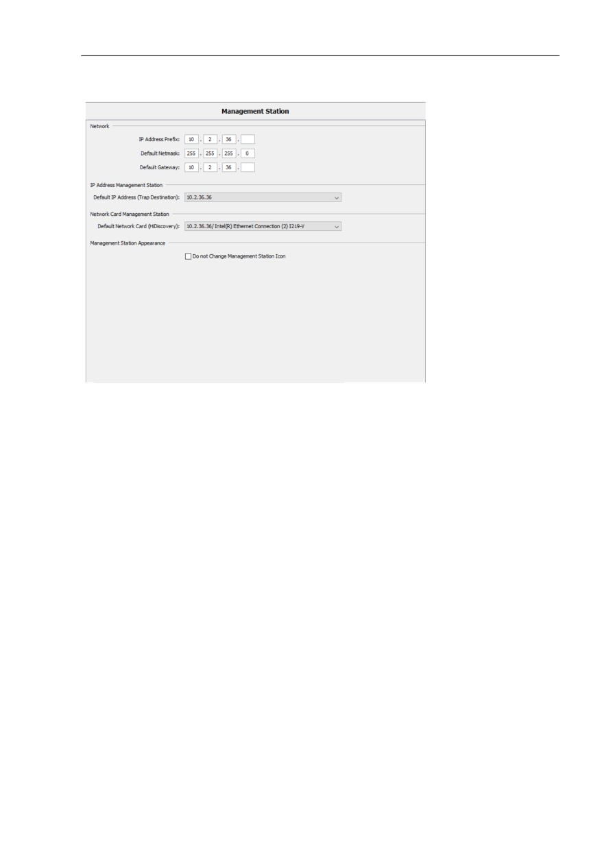
In this dialog you enter the default setting for IP parameters. Industrial
HiVision enters these default settings when you open dialogs where IP
parameter entries are expected for example, IP configuration of devices
which Industrial HiVision detected using HiDiscovery V1.
“IP Address Prefix“:
Here Industrial HiVision enters the prefix of its own IP address.
“Default Netmask“:
Here Industrial HiVision enters the network mask of its own IP address.
“Default Gateway“:
Here Industrial HiVision enters the prefix of the gateway which your
network management station also uses.
“IP Address Management Station“:
If your network management station has a number of IP addresses, then
Industrial HiVision enters these IP addresses in the drop-down list.
Select the address you want to use as a trap destination address.
“Network Card Management Station“:
If your network management station has a number of network cards, then
Industrial HiVision enters these cards in the drop-down list.
Select the card which you want the HiDiscovery V1 protocol to access.
“Management Station Appearance“:
When the “Do not Change Management Station Icon“ function is active
and Industrial HiVision discovers a device on which the kernel is running,
then Industrial HiVision keeps the icon for the device.
384
References
Preferences > Advanced > Management Station
Figure 94: Configuration > Preferences > Advanced > Management Station
385
References
Preferences > Advanced > OPC-SNMP
Preferences > Advanced > OPC-SNMP
OPC-SNMP
The OPC server of Industrial HiVision allows you to use an OPC client
query to determine SNMP values for devices.
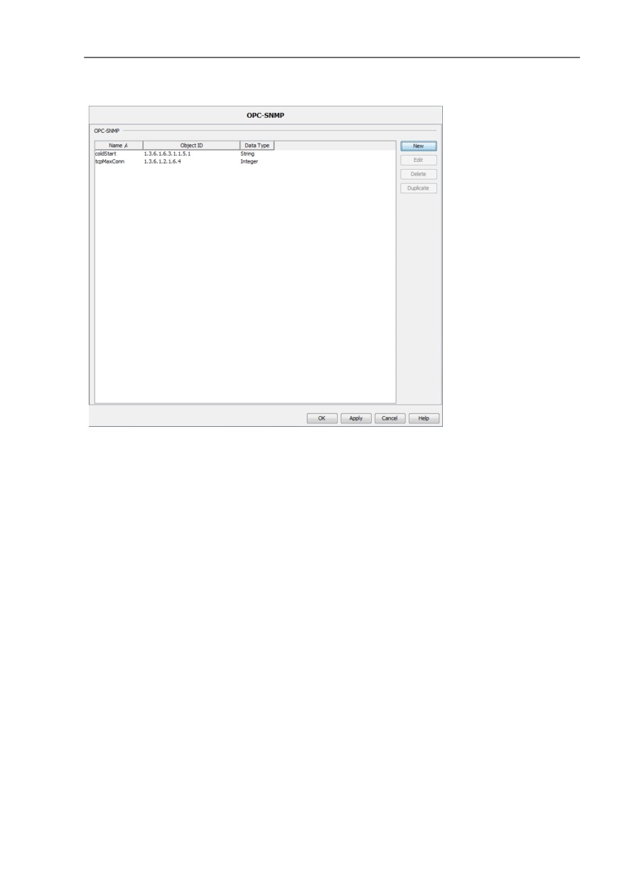
In the Advanced > OPC-SNMP dialog you enter the SNMP attributes whose
values you want to determine. In the table, you can
- add new entries
- edit existing entries
- delete existing entries
- duplicate existing entries
In the “Edit“ and “New“ dialogs, you can enter the SNMP attributes
directly, or select them from an MIB.
To select an SNMP attribute from a MIB, click the “Select MIB Attribute...“
button. In the “MIB Viewer“ dialog, select an SNMP attribute. To load
additional MIBs, you can use the “MIB Manager“ button.
Give the entry a brief, meaningful name, as this will be used later on for
the query in the OPC tag.
If you use an Object Identifier (OID) in the OPC tag, you enter the
complete OID, including any existing instance.
The OPC tag for an OPC client query is, for example:
Industrial_HiVision.snmp.get.10:0:1:159,161,ifAdminState
Whereby:
10:0:1:159 is the IP address of the device, with a colon instead of a
dot as a separator
161 is the SNMP port
ifAdminState is the name of the SNMP attribute, as configured in the
settings
386
References
Preferences > Advanced > OPC-SNMP
Figure 95: Configuration > Preferences > Advanced > OPC-SNMP
387
References
Preferences > Advanced > Service Parameters
Preferences > Advanced > Service Parameters
Service Parameters
The Industrial HiVision program starts its own service. Your PC operating
system displays this Industrial HiVision service for you.
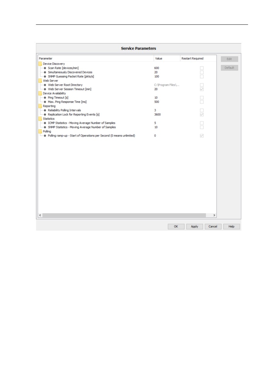
The Industrial HiVision service is made up of the following services:
“Device Discovery“
-
“Scan Rate [devices/min]“
This service performs the network scan (see on page 322
“[Basics]”). The scan rate limits the number of pings/minute.
Default setting: 600
-
“Simultaneously Discovered Devices“
This setting allows you to modify the network load during the device
discovery. Here you enter the number of devices that Industrial
HiVision simultaneously queries during the device discovery.
Default setting: 20
-
“SNMP Guessing Packet Rate [pkts/s]“
With this setting you define up to how many guess packets per
second Industrial HiVision sends to an unknown SNMP device to
discover the login data.
Default setting: 100
“Web Server“
-
“Web Server Root Directory“
The parameter displays the Industrial HiVision web server base
directory.
-
“Web Server Session Timeout [min]“
This parameter allows you specify the maximum idle time for web
server sessions.
Default setting: 20
388
References
Preferences > Advanced > Service Parameters
“Device Availability“
These settings allow you to adjust Industrial HiVision to the ping
response behavior of your devices.
-
“Ping Timeout [s]“
If the ICMP device responds to a ping request within this period,
then Industrial HiVision classifies the device as still present, if it
responded to the last request.
-
“Max. Ping Response Time [ms]“
If the ICMP device responds to a ping request within this period,
then Industrial HiVision detects that the device is present again, if
it did not respond to the last request.
Lower values improve the performance of Industrial HiVision. If the
values are too low, the ping response may come too late and Industrial
HiVision displays the device as “unreachable”. With large subnetworks
that can display short term interrupts, you should use smaller values.
Larger values can cause status changes to be displayed late in
Industrial HiVision.
“Reporting“
-
“Reliability Polling Intervals“
The value queried was recorded a longer time ago than the
maximum number of polling intervals x the polling interval [s] of the
property query (see on page 283 “Properties of a component
detail”).
-
“Replication Lock for Reporting Events [s]“:
The retry block helps you to reduce how often repeating events are
recorded in the event list.
Default setting: 3600
Industrial HiVision records reporting events of the “Warning“ and
“Error“ types if their last recording was further back than the
duration of the retry block.
The changed value is applied only after the Industrial HiVision
server is restarted.
389
References
Preferences > Advanced > Service Parameters
“Statistics“
-
“ICMP Statistics - Moving Average Number of Samples“
The entry specifies the moving average which is computed based
on a subset of response times.
Default setting: 5
The moving average is included as a property type per device in
protocol properties and can be added to the reporting tool.
-
“SNMP Statistics - Moving Average Number of Samples“
The entry specifies the moving average which is computed based
on a subset of response times.
Default setting: 10
The moving average is included as a property type per device in
protocol properties and can be added to the reporting tool.
“Polling“
-
“Polling ramp-up - Start of Operations per Second (0 means
unlimited)“
This parameter allows you to specify the rate of polling operations
started per second. This rate represents the number of new
operations that are added to the polling engine until each polling
operation is handled.
Possible values: 0..1000
Default setting: 0
The value 0 means that the polling ramp-up is disabled and every
enabled polling operation starts at the same time.
The changed value is applied only after the Industrial HiVision
server is restarted.
390
References
Preferences > Advanced > Service Parameters
Figure 96: Configuration > Preferences > Advanced > Service Parameters
391
References
Preferences > Advanced > External Applications
Preferences > Advanced > External Applications
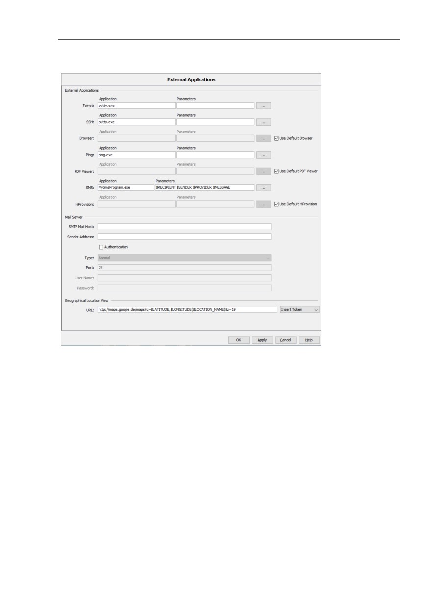
External Applications
Industrial HiVision uses external auxiliary programs for the following
functions:
“Telnet“
“SSH“
“Browser“
On Linux systems, Industrial HiVision uses Mozilla Firefox as the
standard browser. If you want to use a different browser, enter the path
to your browser in the “Browser“ line.
“Ping“
“PDF Viewer“
“SMS“
“HiProvision“
If you have installed the HiProvision program in the Industrial HiVision
installation directory, then you can mark the “Use Default HiProvision“
checkbox.
If you have installed the HiProvision program in another location, then
type in the location in the “HiProvision“ text field.
For further information about the “HiProvision“ program see
“HiProvision” on page 125
“Mail Server“
To carry out email configuration
“Geographical Location View“
URL entry for summoning the geographic location display program for
example, maps.google.
http://maps.google.de/maps?q=$LATITUDE,$LONGITUDE($NAME)&z=19
See “Geographical Location View” on page 302.
392
References
Preferences > Advanced > External Applications
393

References
Preferences > Advanced > Device/Port Names
Preferences > Advanced > Device/Port Names
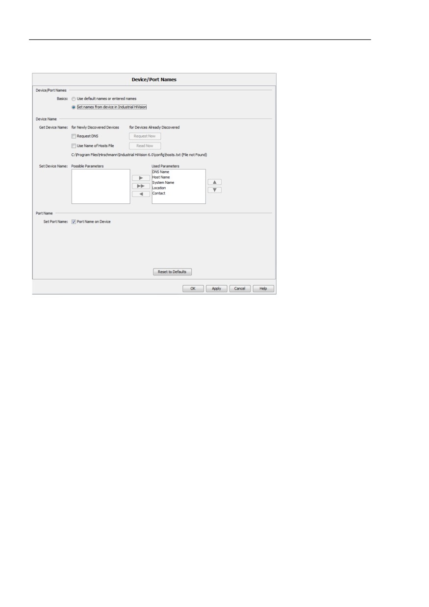
Device/Port Names
With this dialog you manipulate the names of the devices and ports in the
respective Properties dialog and thus their representation in the user
interface.
You first select whether Industrial HiVision displays the devices and ports
with their preset names, or whether Industrial HiVision determines the
names from the device.
When adding new devices to Industrial HiVision, the “Device/Port Names“
frame allows you to select the method in which Industrial HiVision
displays the device names.
The “Basics“: “Use default names or entered names“ function allows
Industrial HiVision to display new devices with the IP address.
The “Basics“: “Set names from device in Industrial HiVision“ function
allows Industrial HiVision to display the name of the new devices.
Note: The “Reset to Defaults“ button only resets the “Device/Port
Names“ dialog to the default settings.
To change the manner in which Industrial HiVision displays the device
name, proceed as follows:
Delete the device from Industrial HiVision.
Open the “Device/Port Names“ dialog for the desired results.
Rescan the network for the device.
Determining device names
Request DNS
when it detects a new device, Industrial HiVision
determines the device name from the Domain Name
Server.
Request Now
For the devices already detected, Industrial HiVision
determines the device name from the Domain Name
Server. This procedure can take some time.
Use Name of Hosts File
For the devices already detected, Industrial HiVision
reads the device name from the hosts file. The hosts file
is the hosts.txt text file in the config subdirectory of
the installation directory.
The hosts file contains a row for each device with the IP
address and the name, separated by a tab.
Read Now
For the devices already detected, Industrial HiVision
reads the device name from the hosts file.
394
References
Preferences > Advanced > Device/Port Names
Industrial HiVision writes the host name and the DNS name into the MAC/
IP address assignment table (see on page 411 “MAC/IP List”).
“Set Device Name“
This frame enables you to choose which name Industrial HiVision puts
into the name field of the device property for the device. Industrial
HiVision displays this name in the folder frame and in the detail display.
Possible parameters are as follows:
-
“DNS Name“
–
“Host Name“
–
“System Name“
–
“Location“
–
“Contact“
By selecting it and clicking on the arrow buttons, you move the potential
names between the “Possible Parameters“ and “Used Parameters“
tables. Industrial HiVision takes the name at the top in the “Used
Parameters“ table. If the relevant entry is empty for a device, Industrial
HiVision takes the name in the next position. If Industrial HiVision does
not find an entry for the device, then Industrial HiVision takes the
management IP address of the device.
“Port Name“
The “Set Port Name“ function allows you to take the port name entered in
the device into the name field of the port properties, as long as the port
names are entered in the device. Industrial HiVision displays these names
in the folder frame and in the detail display. If there is no setting here,
Industrial HiVision displays the IP address for devices and the port
number for ports.
Note: When it detects a device/port, Industrial HiVision takes the name
selection that is set. If you subsequently change this selection, it becomes
effective after you have reset the device/port name. To do this, you select
the relevant devices and right-click “Set Device and Port Names“.
395
References
Preferences > Advanced > Device/Port Names
Figure 97: Assignment of device and port names
396

References
Preferences > Advanced > Load/Save
Preferences > Advanced > Load/Save
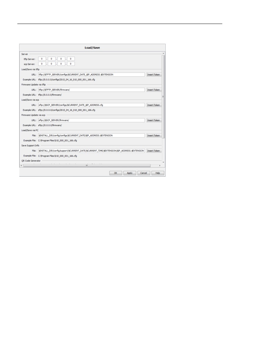
Load/Save
This dialog allows you to enter the following parameters:
- Enter the IP address of a tftp server available in the network
- File name with path
- URLs.
Industrial HiVision automatically enters this into the dialogs in which you
perform file transfer actions for example, loading/saving configurations in
the MultiConfig™ dialog.
This spares you having to enter the URL and the file name multiple times
when you call up the “MultiConfig™” dialog.
Placeholder
Meaning
$INSTALL
Installation folder of Industrial HiVision on the network
management station.
$TFTP_SERVER
IP address of the tftp server that you entered in the
Configuration > Preferences > Advanced > Load/Save dialog.
$IP_ADDRESS
IP address of the device from which Industrial HiVision reads the
configuration, or onto which Industrial HiVision writes the
configuration. Industrial HiVision applies the IP addresses from
the table of the Object frame.
$SYSTEM_NAME
System name of the device from which Industrial HiVision reads
the configuration, or onto which Industrial HiVision writes the
configuration.
$CURRENT_DATE
Current date of the network management station.
$CURRENT_TIME
Current time of the network management station.
$EXTENSION
File name extension:
cfg for binary file
cli for script file
html for HTML file
Table 46: Placeholders supported
397
References
Preferences > Advanced > Load/Save
Figure 98: Configuration > Preferences > Advanced > Load/Save
398
References
Preferences > Advanced > 1:1 NAT Devices
Preferences > Advanced > 1:1 NAT Devices
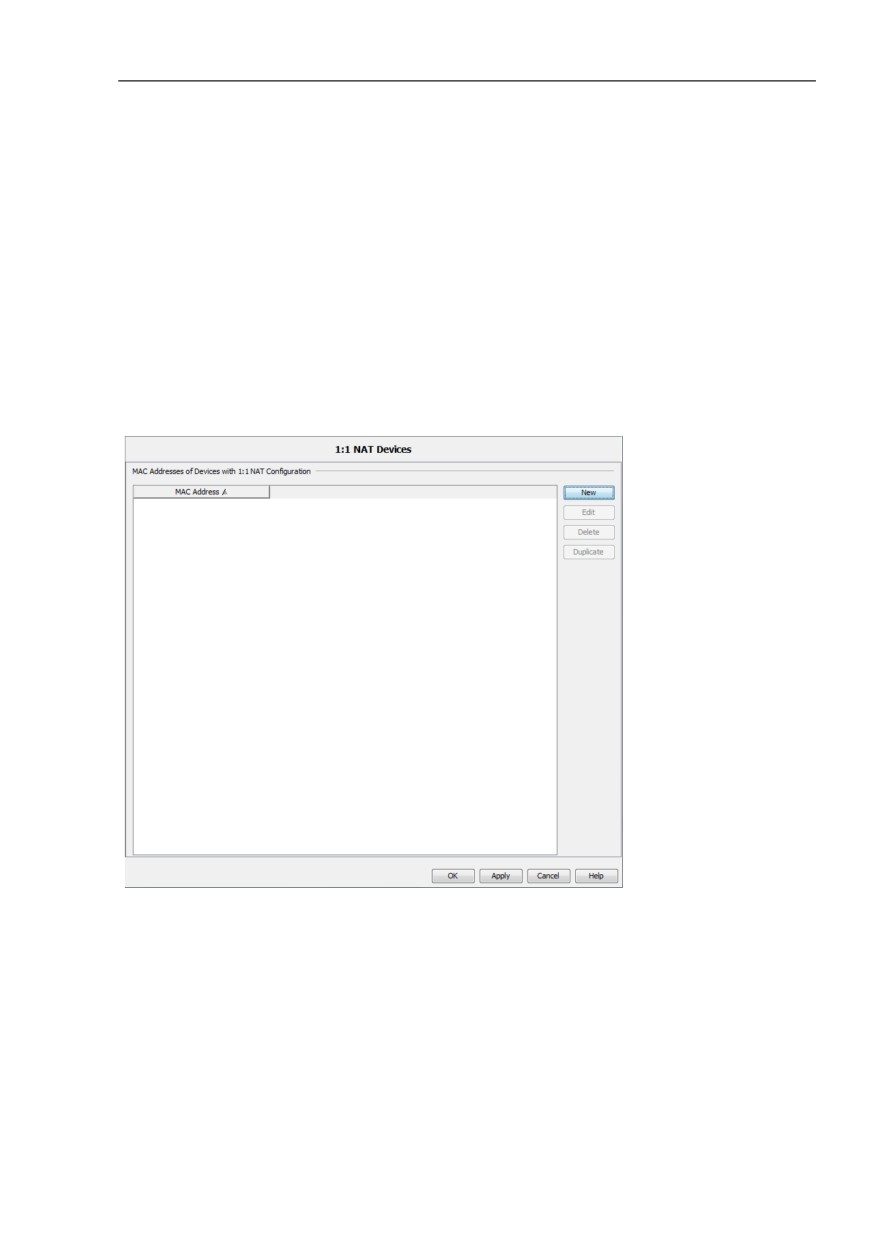
1:1 NAT Devices
This dialog allows you to use Industrial HiVision to manage and monitor
devices behind a 1:1 NAT router.
For Industrial HiVision to be able to detect the devices behind the 1:1 NAT
routers, you enter the MAC addresses of the ports (of the 1:1 NAT
routers) that are connected to the network management station in this list.
You will find the port MAC address in the properties dialog of the 1:1 NAT
router, on the “MAC/IP Addresses“ tab.
Figure 99: Configuration > Preferences > Advanced > 1:1 NAT Devices
399
References
Preferences > Advanced > Mobile Devices
Preferences > Advanced > Mobile Devices
Mobile Devices
When you send a HiMobile request to Industrial HiVision for the first time,
Industrial HiVision registers your mobile device.
In the “Push Notification“ column, you activate/deactivate the sending of
push notifications to the registered device.
Default setting: active
To delete a registered device, you select the row in the table and click the
“Delete“ button.
Industrial HiVision sends push notifications to the devices with an active
entry in this table. To send push notifications, Industrial HiVision requires
Internet access.
After a restart or an update of Industrial HiVision, if the entry for your
mobile device is missing from the list, close HiMobile on your mobile
device. To register the mobile device in Industrial HiVision, start HiMobile.
In the event actions, you define when Industrial HiVision sends which
push notifications.
(see on page 334 “Event Actions”)
400
References
Preferences > Advanced > PoE
Preferences > Advanced > PoE
PoE
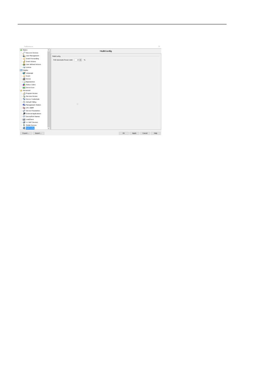
“Automate Power Limit“
The “Automate Power Limit“ function and the “Power Limit“ function
enable the device to send traps and the application to send warnings,
about the power consumption at port level.
To set the “Automate Power Limit“ function, configure the overhead
percentage, which influences the “Power Limit“ value displayed in the
“PoE“ tab, “Module / Port“ view.
The overhead percentage is a configurable parameter, used in the
formula, “Power Limit“ = “Max Cons“ + overhead percentage. To
calculate the overhead percentage use the formula, overhead
percentage = “Max Cons“ x “Automate Power Limit“. The default
“Automate Power Limit“ value is 10. You configure the overhead
percentage in the Preferences > Advanced > PoE > Automate Power
Limit dialog.
To configure the overhead percentage on the PoE ports, proceed as
follows:
Click the “Preferences“ button.
Open the Advanced > PoE dialog.
Specify the PoE overhead in the “Automate Power Limit“ field.
Click the “OK“ button.
To specify the “Power Limit“ value, see “Power Limit” on page 409
401
References
Preferences > Advanced > PoE
Figure 100:Preferences > Advanced > PoE
402
References
Configuration > Status Configuration
Configuration > Status Configuration
8.5
Status Configuration
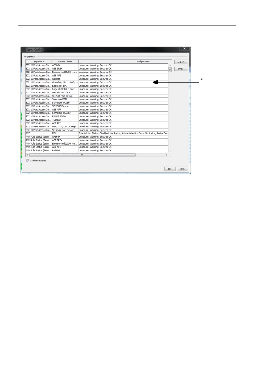
This dialog allows you to configure the status of a component property for the
devices of a device class across the device boundaries or for every devices
simultaneously.
The dialog displays a table of the device classes and their possible
properties.
To display the properties of every device class, mark “Combine Entries“
checkbox. To display the property per device class, unmark the “Combine
Entries“ checkbox.
To specify the values of the property, double-click on a row in the table.
Industrial HiVision opens the corresponding “Status Configuration“ dialog.
Assign the desired status to the values and click the “OK“ button.
To change the properties of those devices that you previously configured
individually, mark the “Overwrite all Properties“ checkbox.
Industrial HiVision accepts this “Status Configuration“ for the devices in this
class.
This function is useful for example, if you require the highest availability
within a HIPER Ring. Then the default setting, “Warning“ is too low for a loss
of redundancy functionality. In the “Status Configuration“ dialog, you can use
a single step to set the status for “No redundancy” to “Error“ for the devices
in a class.
403
References
Configuration > Status Configuration
Figure 101:“Status Configuration“ * Double-click on a row
404
References
Configuration > Scan Ranges
Configuration > Scan Ranges
8.6
Scan Ranges
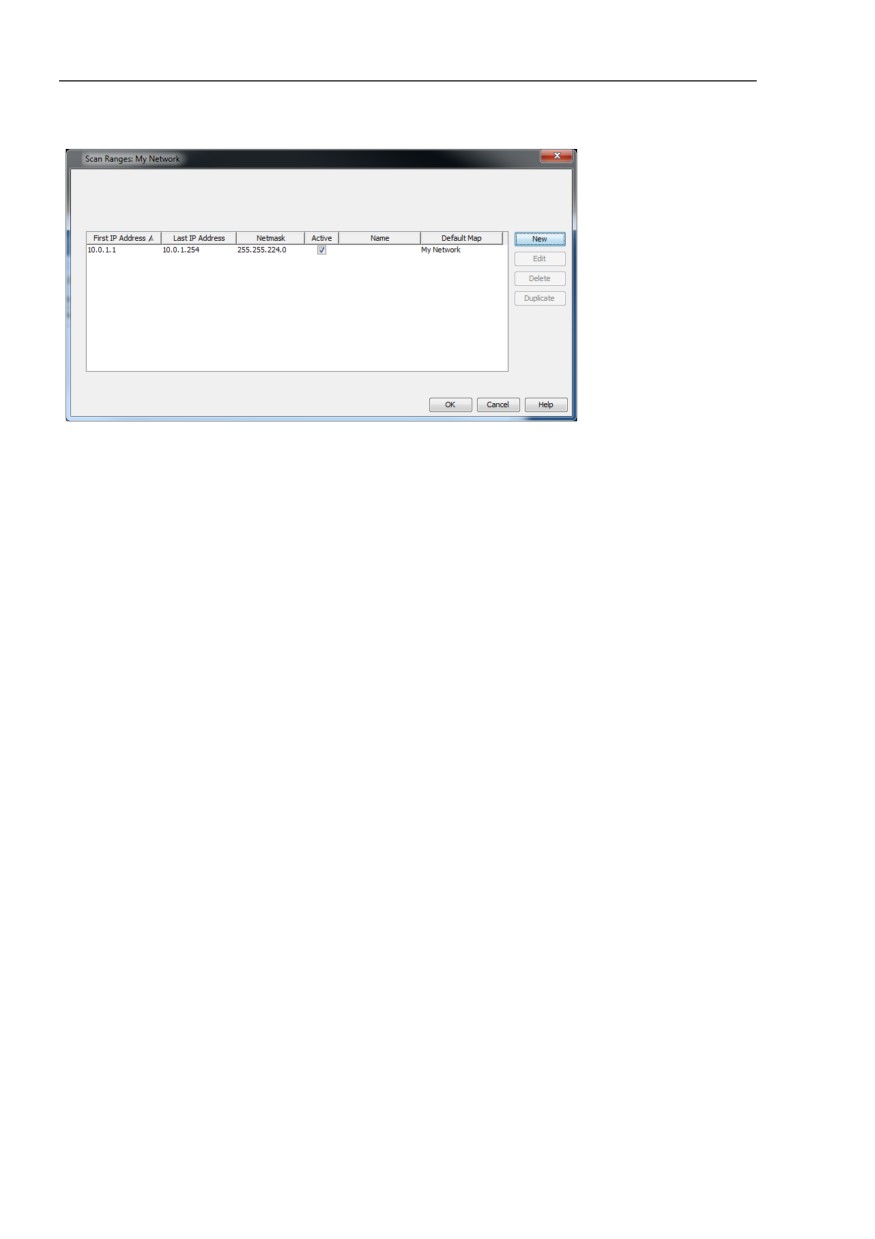
This dialog allows you to enter the scan range for a selected folder.
After selecting a folder in the folder frame, or when the detail display is
active, you select Configuration > Scan Ranges or right-click on Scan
Ranges in the selection menu.
To enter an IP address range, click the “New“ button. Entering the IP
address range consists of the following parameters:
- the first IP address of the query range
- the last IP address of the query range
- the related network mask
- the activation/deactivation of this range for the query
- the name you want to give to the range
Industrial HiVision has already entered the selected folder or the active detail
display as the target folder.
The table displays the IP address ranges already created.
To edit an IP address range, select a row in the table and click the “Edit“
button.
To delete a row from the table, select a row in the table and click the
“Delete“ button.
To duplicate an IP address range so that you can then modify the copy,
select a row in the table and click the “Duplicate“ button.
405
References
Configuration > Scan Ranges
Figure 102:Scan ranges for a folder
Note: Keep in mind that the network masks in this dialog correspond with the
network masks within your network, so that the detection executes properly.
If the network mask within your network is bigger than the network mask of a
scan range, Industrial HiVision skips the highest IP address within the
network mask of the scan range during the scan network, because this IP
address is a broadcast address.
If the network mask within your network is smaller than the network mask of
a scan range, Industrial HiVision scans the highest IP address within the
network mask of the network. Because this IP address is a broadcast
address, every device replies and Industrial HiVision recognizes a device
that does not exist.
406

References
Configuration > User defined Properties
Configuration > User defined Properties
8.7
User defined Properties
This dialog allows you to enhance and monitor the properties of any SNMP-
capable devices in Industrial HiVision (see on page 219 “Description of user-
defined properties”).
In the menu bar, select Configuration > User defined Properties to
open the “User defined Properties“ dialog.
You can edit, delete or duplicate a selected user-defined property. When you
select a user-defined property, the “Delete“ button remains grayed-out if this
property is assigned to a higher-level property.
8.7.1
Creating a new user-defined property
You can find an application example in the chapter “Setting up the network
monitoring” (see on page 219 “Application example for user-defined
properties”).
Name
Meaning
Name
A freely-selectable, unique name for this property starting with
“UserDef_”, e.g. “UserDef_ICMP-Message”.
Label
A freely-selectable name that Industrial HiVision uses for the
display in the user interface.
Icon
A pixel file is selected that Industrial HiVision displays as a
symbol for the property in the user interface.
Parent Property
The higher-level property of the new property for example, the
property “Speed” belongs to the higher-level property “Port”.
MIB Variable/OID
MIB variable/OID (object identification) that you can select by
clicking on the three dots in the MIB browser.
Instance
Assignment of the MIB variants to a device detail, e.g. “0” for
the time.
Alternatively, Industrial HiVision determines the type itself for
example, “Module Number”.
Table 47:
“New Entry” dialog for a user-defined property.
407

References
Configuration > User defined Properties
Name
Meaning
Type
Industrial HiVision selects the type for example, a MAC
address or an integer, automatically if Industrial HiVision can
determine the type.
Mapping
Assignment of a numerical value to a meaning for example,
“0 = false” or “1 = true”. Industrial HiVision determines this
value from the MIB.
Factor
Factor for converting a unit for example, Celsius to Fahrenheit.
Offset
Offset for converting a unit for example, Celsius to Fahrenheit.
Table 47:
“New Entry” dialog for a user-defined property.
408
References
Configuration > MultiConfig™
Configuration > MultiConfig™
8.8
MultiConfig™
The multi-configuration function (MultiConfig™) allows you to perform
configurations on the device and in Industrial HiVision for:
one or more devices
one or more device properties, also device overlapping
one or more device details, also device overlapping
You can find more information with application examples in chapter
“Configuring the network” on page 157.
8.8.1
Power Limit
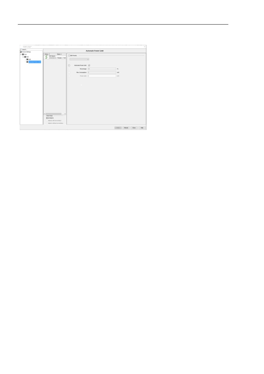
To configure the “Power Limit“ function on the “PoE“ ports, proceed as
follows:
Select the PoE ports in your network that need the same threshold.
Right-click a selected port. A drop-down list opens.
Select the “MultiConfig™“ option.
Open the Device Settings > PoE > Automate Power Limit dialog.
To configure the “Power Limit“ function, unmark the “Automate Power
Limit“ checkbox.
Specify the necessary value, in the “Power Limit“ field. When the power
is above this threshold, the device sends a trap and the application sends
a warning.
To automate the “Power Limit“, mark the “Automate Power Limit“
checkbox.
Click the “Write“ button.
Click the “Close“ button.
409
References
Configuration > MultiConfig™
Figure 103:Configuration > MultiConfig™ > Device Settings > PoE > Power
Limit
410