Network Management System Industrial HiVision 8.2. User Manual (2021) - page 9
References
8.1 File
8.1
File
The “File“ menu contains functions relating to file operations.
Industrial HiVision performs file operations on the computer with whose
“Hirschmann Industrial HiVision 8.2 Service” service your interface
communicates. If you have installed the service and the user interface on
different computers, you get the file selection dialog for the file selection (see
figure 52).
You double-click on a table row to go one level lower on the file tree
structure.You click “Up“ to go one level higher in the file tree structure.
Above the table you see the path you are currently on.
Figure 52: File selection dialog for different computers
254
References
8.1 File
8.1.1
New Project
You can use this selection to create a new project in which you can save your
network data.
Note: By selecting “New Project“ you delete the current project. To save
the data of the current project, you export this project under another name
before selecting the new project (see on page 257 “Save”).
8.1.2
New
You use this selection for the following functions:
to add a new folder
to add a new device to the selected folder
to add a new device from a list to the selected folder
to add a new subdomain the selected folder
to create a new connection
to add counters with properties on the port level for example
“In non Unicast Packets”.
to add a text line
to add a symbol. You can change the symbol in the “Properties...“ window
of the symbol.
Devices from List
Industrial HiVision allows you to scan IP addresses using a text or an
Microsoft Excel csv file. The “Create Devices from List“ dialog allows you
to search for and upload the file to Industrial HiVision. If a device in the list
is unreachable, then Industrial HiVision displays the device in the
topology map as a generic device.
255
References
8.1 File
The “Create Devices from List“ dialog allows you add the IP addresses
contained in the file to the Preferences > Basics > Discover Devices >
Network Scan table. When you mark the “Add IP addresses to
'Preferences - Basics - Discover Devices - Network Scan'“ checkbox,
Industrial HiVision enters the IP address ranges from the text file into the
table.
When you mark both the “Add IP addresses to 'Preferences - Basics -
Discover Devices - Network Scan'“ and the “Combine consecutive IP
addresses into ranges“ checkboxes, Industrial HiVision enters the IP
addresses to the table in the following manner:
If the IP addresses in the file are within a range of addresses already
present in the table, then Industrial HiVision merges the IP addresses
into the existing address range.
If the IP address range overlaps or is adjacent to a larger existing
range, then Industrial HiVision uses the netmask from the existing
range.
When the function cannot use a netmask from any existent range, the
function automatically assigns the default netmask value
255.255.255.0.
The function merges single adjacent IP addresses into IP address
ranges entered in the same file.
When you create the IP address file use the following formats:
192.168.1.10,
# this is a single address
192.168.1.11
# this is also a single address
192.168.1.12,192.168.1.15,
# this is a range of addresses
192.168.1.16,192.168.1.20
# this is also a range of addresses
# this is a comment line
# 192.168.1.1 this is also a comment line
Note: To separate the IP address ranges, use a comma instead of a
space. The comma at the end of the line is optional. To insert text use the
hash “#” symbol.
256
References
8.1 File
8.1.3
Login
With this selection you can connect the user interface with the service on
your own computer (localhost) or with the service on a remote computer.
8.1.4
Open...
You use this selection to open a previously saved project in order to view it
or make changes in it.
Select the relevant path and the desired file within your folder structure.
Note: Select a path to which both the Industrial HiVision service and you
have access.
8.1.5
Save
You use this selection to save your current network data and the
configuration of Industrial HiVision into a current project file with the
extension .ihp.
Select File > Save, to overwrite the open project file with the current
project and the current configuration of Industrial HiVision.
257
References
8.1 File
8.1.6
Save as...
You use this selection to save your current network data and the
configuration of Industrial HiVision into a project file.
Select File > Save as...
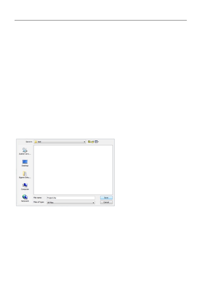
Select the relevant path within your folder structure and enter a project
name.
Note: Select a path to which both the Industrial HiVision service and you
have access.
Click on “Save“ to save the current project and the current configuration
of Industrial HiVision in a new file.
8.1.7
Save Backup
Industrial HiVision lets you save the information you require to restore
Industrial HiVision installation.
For this purpose, Industrial HiVision writes the following information in a ZIP
file:
PSM list and PSMs
Configuration (service properties files)
Project database
Reporting database
License files
Log files
User reports
User scripts, tasks and task results
info.txt file with version information
Upon summoning “Save Backup“, Industrial HiVision opens a file selection
dialog. You are able to specify the destination of the backup file here.
258
References
8.1 File
Note: To load the backup file you require the same version of Industrial
HiVision that you used to write the backup file. You will find version
information in the info.txt file in the backup zip file
8.1.8
Load Backup
Industrial HiVision allows you to restore a damaged Industrial HiVision
installation.
For this purpose, a Industrial HiVision backup ZIP files contains the following
information:
PSM list and PSMs
Configuration (service properties files)
Project database
Reporting database
License files
Log files
User reports
User scripts, tasks and task results
info.txt file with version information
After starting “Load Backup“, Industrial HiVision opens a file selection dialog.
You are able to specify the location of the backup file.
Note: To load the backup file you require the same version of Industrial
HiVision that you used to save the backup file. You will find the version
information in the info.txt file in the backup zip file.
259
References
8.1 File
8.1.9
Export...
With this selection you export the content of the detail display.
Industrial HiVision exports graphics (topology representation) as a:
PDF file,
jpg file,
png file and
bmp file.
Industrial HiVision exports tables as a:
PDF file
HTML file
CSV file (see on page 457 “CSV export”)
Select File > Export... and select the file type in the “Save“ window.
8.1.10 Export Events...
With this selection you export the complete event list as:
PDF file
HTML file
CSV file (see on page 457 “CSV export”)
Select File > Export Events... and select the file type in the “Save“
window.
260
References
8.1 File
8.1.11 Print
With this selection you print the content of the detail display.
Select File > Print.
Industrial HiVision creates a temporary PDF file of the content of the detail
display and opens this PDF file in the PDF display program for example,
Acrobat Reader, that is installed on your management station.
8.1.12 Print Events
With this selection you print the complete event list.
Select File > Print Events.
Industrial HiVision creates a temporary PDF file of the content of the detail
display and opens this PDF file in the PDF display program for example,
Acrobat Reader, that is installed on your management station.
8.1.13 Exit and Stop Service
This selection is available when running on the Windows operating system.
With this selection you exit both the program and, for the local service, the
service. By exiting the service you also interrupt the monitoring of your
network.
261
References
8.1 File
8.1.14 Exit
You use this selection to quit the program. The service remains active in the
background and continues to monitor your network.
262
References
8.2 Edit
8.2
Edit
The “Edit“ menu contains functions relating to editing operations and device
properties.
8.2.1
Undo
With this selection you undo the last change you made in the program.
8.2.2
Redo
With this selection you redo the last change you made in the program, which
you had previously undone.
8.2.3
Edit Mode
You use this selection to activate/deactivate the “Edit Mode“.
You require the relevant access rights for this function, see “Edit Mode” on
page 84.
To avoid writing conflicts, Industrial HiVision prevents the “Edit Mode“ from
being activated on multiple user interfaces at the same time.
263
References
8.2 Edit
8.2.4
Switch to the free version
With this selection you switch during the free 30-day trial period between the
licensed version and the free version.
Industrial HiVision offers 3 versions:
Licensed version
After you enter a license key, Industrial HiVision runs as the licensed
version. As the licensed version, Industrial HiVision gives you the full
function range.
Free 30-day trial version (licensed)
After a new installation or after an update, Industrial HiVision starts fully
functional for the duration of the free 30-day trial period.
During the last 7 days of the trial period, a message window tells you that
the trial period is running out and that you can save the project file before
the trial period expires. If Industrial HiVision is idle during this time,
Industrial HiVision shows this message window when it starts again.
Free version
As the free version, Industrial HiVision offers the option of detecting
devices of Hirschmann and performing updates on the detected devices.
8.2.5
Cut
You use this selection to put data you have selected (screen element,
components, devices with their settings) into the clipboard.
The data is deleted, and you can add it in again at another position using the
“Paste“ menu item.
You can also copy the names of objects into other applications, such as a
text editor.
264
References
8.2 Edit
8.2.6
Copy
You use this selection field to put data you have selected (screen element,
components, devices with their settings) into the clipboard.
The data remains where it is, and you can add a copy of it at another position
using the “Paste“ menu item.
You can also copy the names of objects into other applications, such as a
text editor.
8.2.7
Paste
You use this selection field to add the data (screen element, components,
devices with their settings) in your clipboard at the position where your cursor
is currently located.
8.2.8
Paste as Link
You use this selection field to add the data (screen element, components,
devices with their settings) in your clipboard as a link at the position where
your cursor is currently located. Only a reference to the data is inserted.
The data themselves remain in their original position (see on page 139
“Creating a link”).
265
References
8.2 Edit
8.2.9
Delete
You use this selection to delete data you have selected (screen element,
components, devices with their settings).
When deleting devices, Industrial HiVision allows you to delete the device or
move the device into the “Unused Devices“ folder.
8.2.10 Rename
With this selection you rename a selected folder or a tagged device.
8.2.11 Select All
You use this selection to select all parts inside the active folder.
8.2.12 Acknowledge Status Change
You use this selection to acknowledge the status change of the selected
components and their sub components.
266
References
8.2 Edit
8.2.13 Manage
With this selection you activate the monitoring of the selected devices (see
on page 267 “Unmanage”).
8.2.14 Unmanage
With this selection you deactivate the monitoring of the selected devices.
Industrial HiVision keeps the device, its configuration and its current values
stored in the database. The monitoring of the device is off until you set it to
“Manage“ again (see on page 267 “Manage”). Industrial HiVision releases
the license of this device and allows you to use this license for another
device.
Industrial HiVision displays a device in the “Unmanage“ state in gray with a
stop symbol.
8.2.15 Set Device and Port Names
With this selection you set the detail window to display the following items:
- the device name and port name of the selected devices, instead of
- the IP address and port numbers of the selected devices.
267
References
8.2 Edit
8.2.16 Set Default Device Icon
With this selection you take the symbol for display from the device class. If
no default symbol exists for the device class, Industrial HiVision takes the
device symbol entered in the preferences (see on page 365 “Device Icon”).
8.2.17 Device Documentation
With this selection, Industrial HiVision generates a PDF file to:
“Document Selected Devices“
“Document All Devices“
The PDF file contains information about the device and its settings.
Make a selection and specify the folder in which you want Industrial
HiVision to save the PDF files.
8.2.18 Drawing Size
You use this selection to adapt the size of the drawing area for the detail
display to meet your requirements. Industrial HiVision provides you with
three options for doing this:
“Enlarge“
“Reduce“
“Shrink to Fit“
268
References
8.2 Edit
8.2.19 Background Image
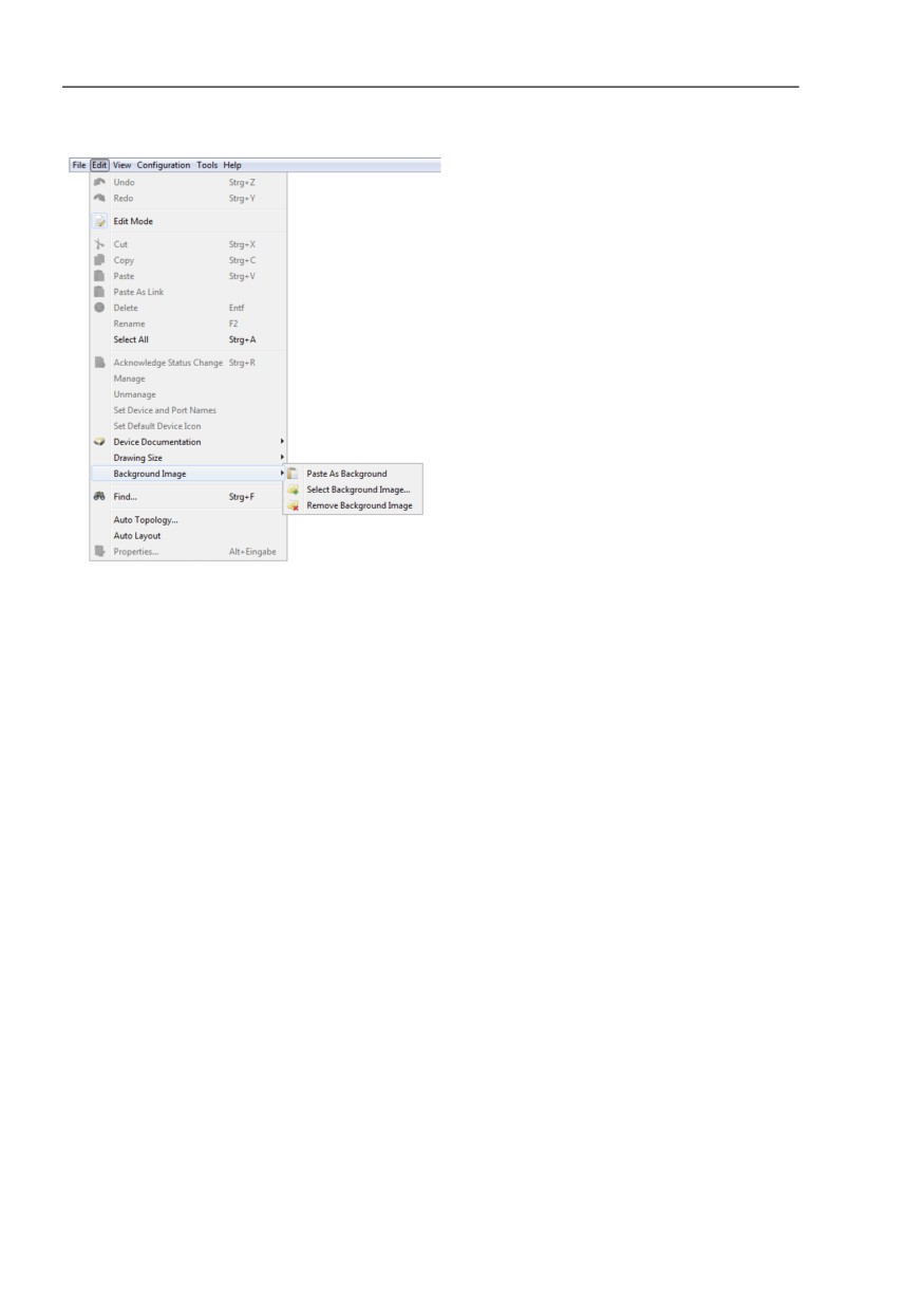
You use this selection field to load, remove or change the background image
in your detail display. The following options are available:
“Paste as Background“
When you select “Paste as Background“, you add the image in your
clipboard to your detail display as a background image. If the clipboard is
empty, this menu item is marked in grey and cannot be selected.
“Select Background Image...“
When you select “Select Background Image...“ you add the image from a
file to your detail display as a background image. Select the relevant path
and the desired file within your folder structure.
Note: High-resolution background images sap the resources of your
network management station and therefore reduce the performance of
your system.
“Remove Background Image“
When you select “Remove Background Image“, you delete the
background image in your detail display.
269
References
8.2 Edit
Figure 53: Edit:Background image
8.2.20 Find...
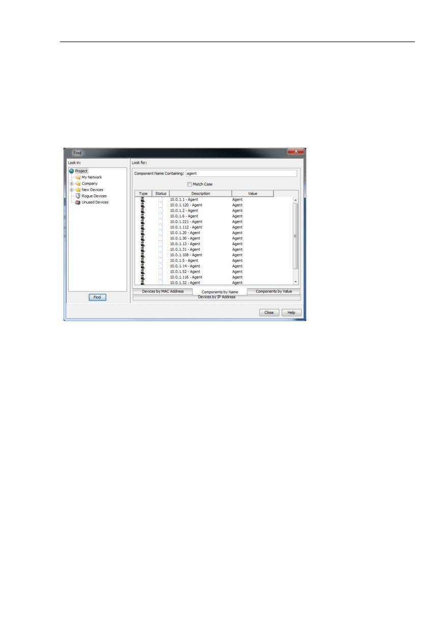
The “Find“ dialog allows you to search for components, MAC addresses or
IP addresses in the display.
Select the “Devices by IP Address“ tab if you are searching for an IP
address or “Components by Name“ if you are searching for part of a
device.
Enter
the IP address/MAC address or a part of it, or
the component name or a part of it without using wildcards.
Select a device on the left of the tree diagram or a folder in which you want
Industrial HiVision to search.
Click the “Find“ button to start searching.
270
References
8.2 Edit
Industrial HiVision displays the result of the search in a list of the search
dialog. When you double-click on a line in this list, Industrial HiVision selects
the component you want to find in the folder frame.
Figure 54: Edit:Find
8.2.21 Auto Topology...
The “Auto Topology...“ function allows you to automatically create the links
between the devices. For the topology discovery, Industrial HiVision uses the
Forwarding Data Base (FDB) and the LLDP and SNMP functions of the
devices.
IEEE 802.1AB describes the Link Layer Discovery Protocol (LLDP). LLDP
enables the user to have automatic topology recognition for his LAN.
Industrial HiVision detects redundancy mechanisms, such as RSTP,
redundant network coupling or HIPER-Ring. Industrial HiVision represents
every redundant connection as a separate connection.
271

References
8.2 Edit
Industrial HiVision can detect the terminal device topology across the
subnetworks if the router separating the subnetworks supports the SNMP
ipNetToPhysicalTable.
Select Edit > Auto Topology...
In the dialog for automatic topology discovery, you select how you want
Industrial HiVision to execute the “Auto Topology...“ function.
Selection
Action
Entire Network (Recommended)
Detects the topology of the entire network, including
switches, routers, WLAN and terminal devices and reads
large data quantities from the devices.
In large networks, Topology Discovery can take up a
significant amount of time.
In this case “Entire Network” means the Layer 2 network
that is connected with the network interface card of the
network management station and all the reachable VLANs.
Infrastructure
Only detects the topology of the infrastructure devices
based on LLDP. Is performed very quickly and sometimes
with gaps.
Table 24:
“Scope“
Selection
Action
Unmanaged Nodes
Industrial HiVision derives topology information from
devices without the management function and from devices
without an Industrial HiVision license from the information in
known neighboring devices. Industrial HiVision represents
these unknown devices as a cloud. A cloud can represent
one or more unknown devices.
Table 25:
“Unmanaged Nodes“
272

References
8.2 Edit
Selection
Action
Create New Topology
Create a completely new topology.
Removes existing connections and clouds. Then creates
new topology.
Complement Topology
Enhance existing topology,
Creates new connections and clouds. The existing
connections are kept.
Update Topology
Adds missing connections and removes connections that
differ from the current topology. Keeps existing clouds if
they correspond to the current topology.
Table 26:
“Strategy“
Selection
Action
Automatic
Industrial HiVision unravels the topology and
reassigns the objects.
Manual
Industrial HiVision leaves the objects in their current
positions.
Table 27:
“Layout“
Selection
Action
Current Folder
Performs the selected actions only in the selected
folder.
Recursive
Industrial HiVision performs the automatic Auto
Topology Discovery in the current folder and in the
folders below it, and displays the results in both the
current folder and the folders below it.
Table 28:
“Range“
Click the “OK“ button.
Then Industrial HiVision queries the links in the network in accordance with
the settings and displays the detected links in the interface.
273
References
8.2 Edit
Note: Topology Discovery
Network components that do not conform to the LLDP specifications or
cannot be managed using SNMP can lead to incorrect Auto Topology
Discovery.
An active DHCP request during the discovery procedure can corrupt the
result of the discovery.
VLAN routing can corrupt the result of the discovery.
MACH 3000 M-Router modules work with VLAN routing.
To detect subnetworks behind 1:1 NAT routers, select “Infrastructure“
under “Scope“(see table 24).
In order to identify the topology with VRRP routers correctly, Industrial
HiVision requires at least one of the VRRP routers to be located in the
same folder or subfolder, where you start the automatic topology function.
Detecting devices of an LAN behind a wireless client device:
The BAT-Devices from Hirschmann have the “client bridge support”
function.
For Industrial HiVision to be able to detect devices of an LAN behind a
wireless client device, activate the “client bridge support” function in the
wireless client device and in the related WAN on the access point.
Redundantly connected terminal devices can corrupt the result of the
discovery.
The topology discovery detects the topology at the time at which it is
executed.
Industrial HiVision displays other changes in the network (e.g. roaming)
when you update the topology display.
Auto Topology for undiscovered devices
The Industrial HiVision “Auto Topology...“ function was made for flat layer
2 topologies. Changes were made for routed topologies, but in rare cases,
the detected topology can be incorrect or not complete. The following
work steps help you make a topology of your entire network.
This step makes the topology with the information that the devices provide
only through LLDP over SNMP.
An example of a device that is in this category is the Dragon PTN.
Do these steps in the root project folder.
Specify the following values in the “Auto Topology“ dialog:
-
“Scope“: Infrastructure
-
“Unmanaged Nodes“: as necessary
–
“Strategy“: Create New Topology
274
References
8.2 Edit
-
“Layout“: as necessary
–
“Range“: Recursive
After Industrial HiVision finishes scanning the devices in the selected
folder, the “Map“ tab displays the network topology. The topology can still
be incomplete.
Rescan your network using the following steps:
Select the desired folder from the folder frame.
Right-click a blank space in the “Map“ tab.
Select “Auto Topology...“ from the drop-down list.
Specify the following values in the “Auto Topology“ dialog:
-
“Scope“: Entire Network (Recommended)
–
“Unmanaged Nodes“: as necessary
–
“Strategy“: Complement Topology
–
“Layout“: as necessary
–
“Range“: Current Folder
8.2.22 Auto Layout
The “Auto Layout“ function gives you the option of leaving the assignment of
the devices to Industrial HiVision.
Select Edit > Auto Layout.
To get Industrial HiVision to reposition the objects in the detailed display,
click the “OK“ button.
275
References
8.2 Edit
8.2.23 Properties of a folder/device
The “Properties...“ dialog contains the “Properties“, “Subcomponents“,
“Status Reason“, “Scan Range“, “Protocols“, “IP Address“ and “MAC/IP
Addresses“ tabs.
The “Protocols“ and “MAC/IP Addresses“ tabs describe device properties.
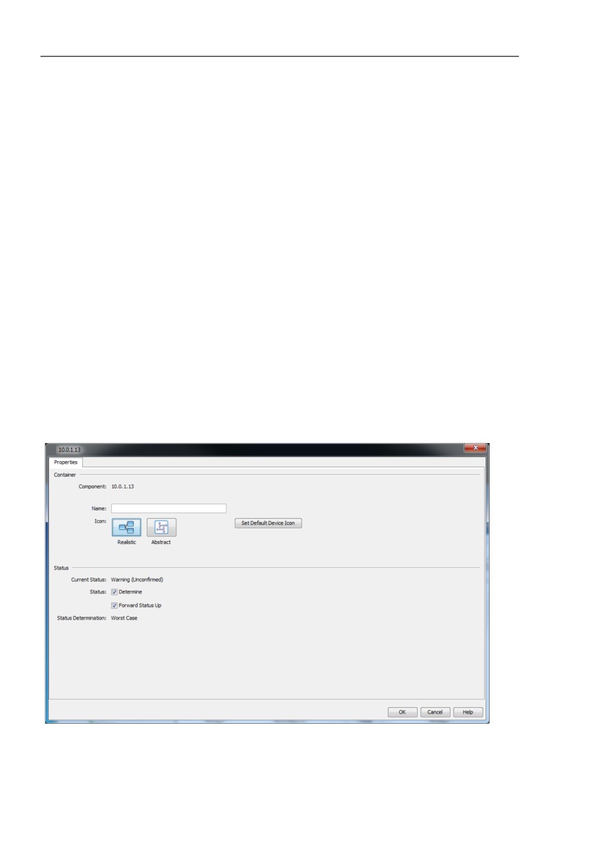
Properties of a folder/device
The “Properties“ tab displays the general properties of the component
display.
You click on a symbol once to open a dialog for selecting an image for
Industrial HiVision to use in the display. Industrial HiVision adapts the
image size automatically.
The status display is important for monitoring your network. Here you
select whether Industrial HiVision determines the status of this
component and whether Industrial HiVision forwards the status
determined to the next highest level. In the basic setting, Industrial
HiVision determines the status and forwards it to the next highest level.
Figure 55: Properties of a folder/device
276
References
8.2 Edit
Subcomponents of a device/folder
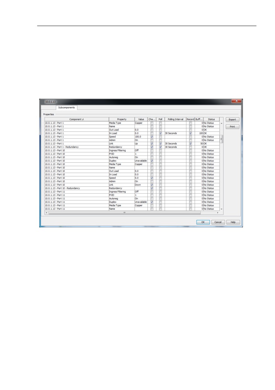
The “Subcomponents“ tab displays a table of the entire parts of the
component from which you can open the “Configuration
Signature“:“Properties“ dialog.
Along with the names of the parts, the table also contains the values of
the different properties of these parts.
Figure 56: Subcomponents of a folder/device
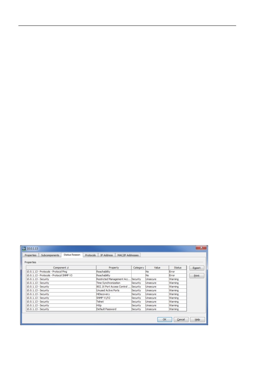
Status Reason
If you hover over an item in the folder pane or in the “Map“ view, then
Industrial HiVision displays a status list containing the current detected
warnings and errors. You can also view the status list in the View >
Properties > Status Reason tab.
The “Status Reason“ tab is available for the following items:
Folders
Devices
Containers - a sub-folder of a device folder
Connections
277
References
8.2 Edit
As an example for this function, the status of a device in your network
continually displays detected errors. You want to maintain a history of the
status list for future reference.
To save the status list as a PDF file, proceed as follows:
Select the device for which you want to save the status list.
On the tool bar, click View > Properties. Industrial HiVision opens the
“Properties“ dialog.
Alternatively, to open the “Properties“ dialog, right-click on the
selected device. In the drop-down list, select the “Properties“ function.
Open the “Status Reason“ tab.
To save the status list on your PC, click the “Export“ button. The “Save”
dialog opens.
Navigate to the location where you want to save the file.
In the “Save> File name” text field, enter an appropriate name for the
file.
In the “Save> Files of type” pull-down list, select “Adobe Portable
Document Format“.
Click the “Save” button.
To close the “Properties“ dialog, click the “OK“ button.
You can save the status list in the following formats:
PDF file
HTML file
CSV file
Note: The “Print“ button opens the status list in your default PDF program.
Figure 57: “Status Reason“ of a folder or device
278
References
8.2 Edit
Scan range of a folder
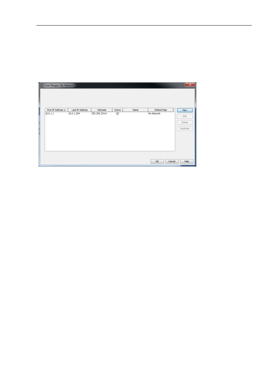
The “Scan Range“ tab enables you to define IP address ranges. Industrial
HiVision displays newly detected devices with IP addresses from one of
these IP address ranges in this folder (see on page 405 “Scan Ranges”).
Figure 58: Scan ranges of a folder
279
References
8.2 Edit
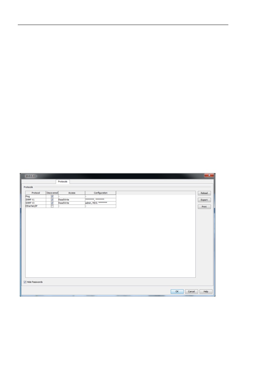
Protocols of a device
The “Protocols“ tab displays a table of the protocols that are supported
and their properties.
Depending on the devices, Industrial HiVision supports the protocols:
Ping
SNMP V1
SNMP V3
HiDiscovery V1
EtherNet/IP
Modbus/TCP
Industrial HiVision supports the Modbus/TCP command Read Device
Identification (43 / 14) exclusively.
Industrial HiVision uses the highest possible protocol (sequence: SNMP
V3, SNMP V1, Modbus/TCP, Ping) to monitor a device.
You use “Reload“ to get Industrial HiVision to query protocols of the
device again.
Figure 59: Protocols of a device
280
References
8.2 Edit
IP address of a device
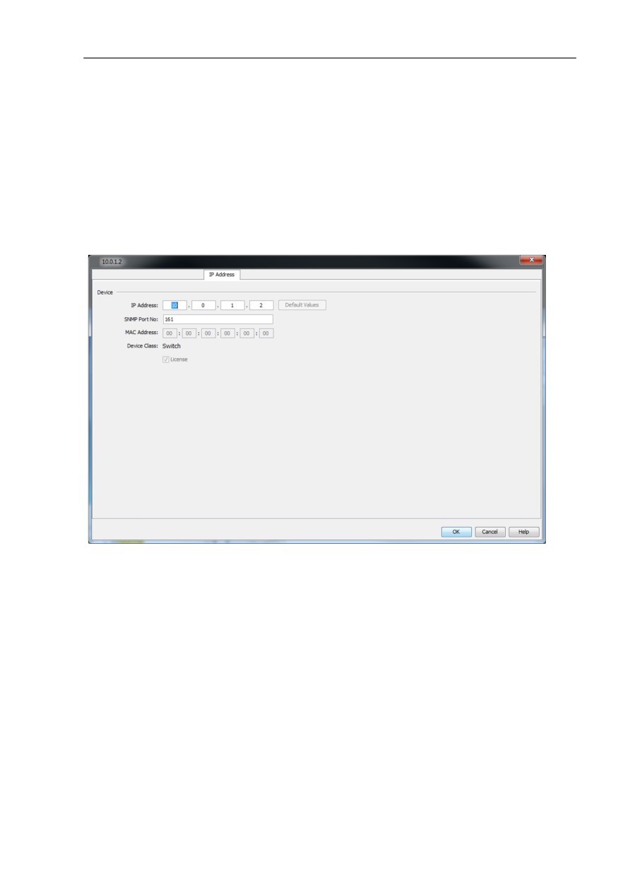
The “IP Address“ tab allows you to change the IP address and the SNMP
port number for current devices for Industrial HiVision in this dialog.
You require this function to re-access a known device with Industrial
HiVision, whose IP address was changed directly on the device.
If you want to change the IP address on a device, you select the device
and use the Configuration > IP Configuration (see on page 414 “IP
Configuration”).
Figure 60: IP address for a current device
281
References
8.2 Edit
MAC/IP addresses of a device
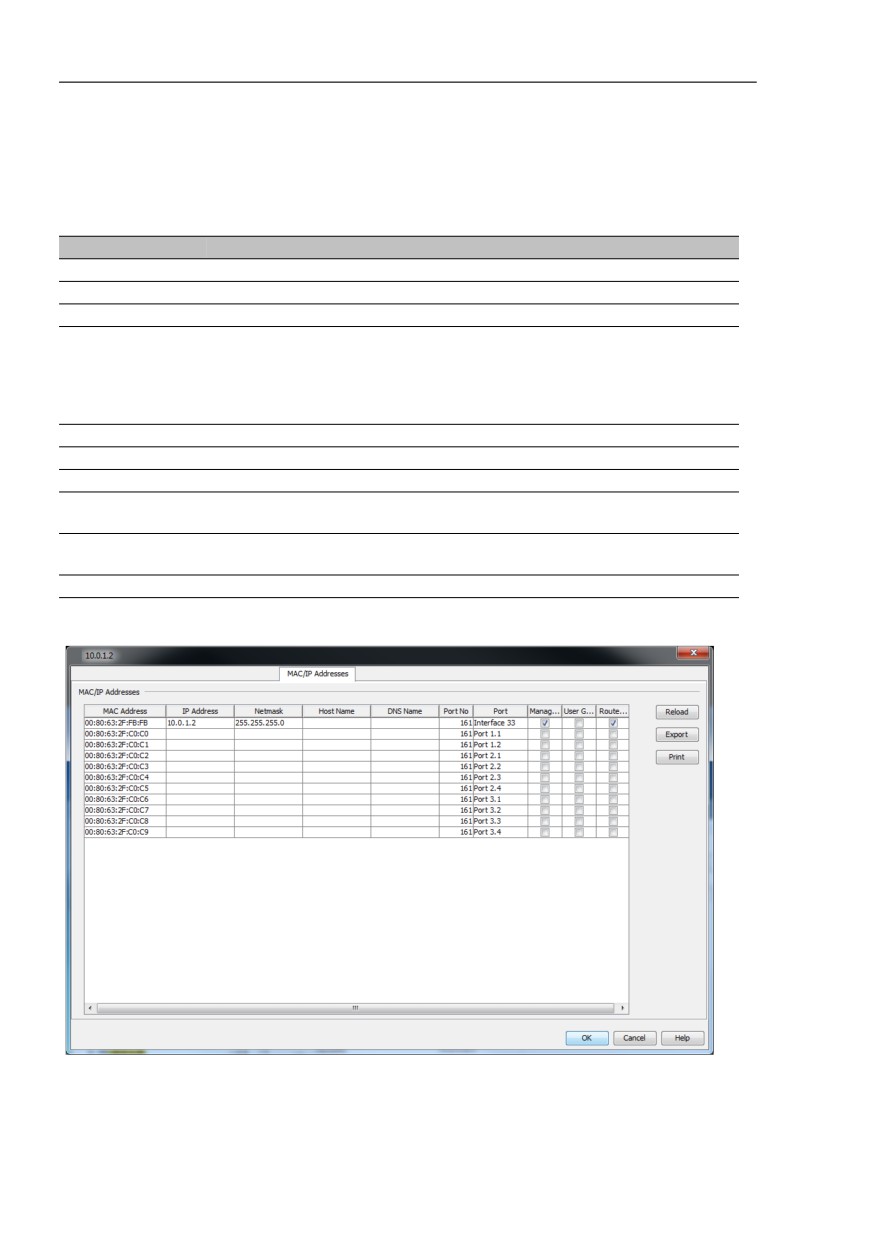
The “MAC/IP Addresses“ tab displays a list of the IP addresses in the
device and their related MAC addresses. The list contains:
Parameter
Meaning
MAC Address
IP Address
Netmask
Host Name
Host name from the /config/hosts.txt file in the installation directory if
the file exists,
there is an entry and
the determination of a device name is activated in the basic settings.
Otherwise, the field remains empty.
DNS Name
Name from the Domain Name Service
Port No
Port number of the protocol.
Port
Device port
Management
Industrial HiVision communicates with the management of the device by
means of the IP address in this row.
User Generated The device in this row was generated by the user. Industrial HiVision has
not detected this device yet.
Router Entry
The IP address in this row comes from the routing table of the device.
Figure 61: MAC/IP address and name of a device
282
References
8.2 Edit
8.2.24 Properties of a component detail
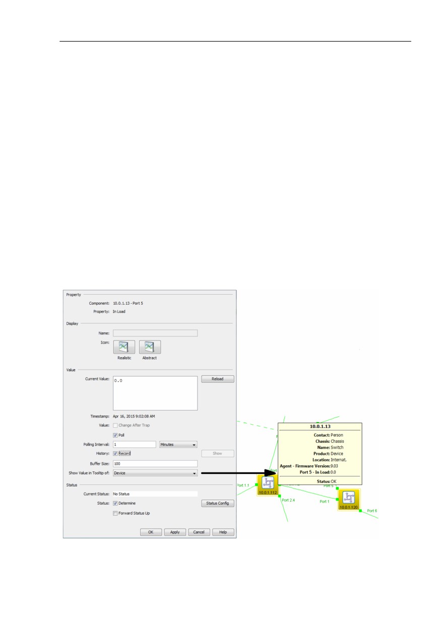
In the “Properties of a component detail” dialog, you are at the lowest level of
the status determination. In addition to the properties that are on higher
levels, this dialog contains a specifically determined value. If you want to
observe this value, you can query it at freely specified intervals and log it.
Value range for the polling interval: ≥5 seconds.
To configure a component detail property proceed as follows:
Select a device or port from the folder frame.
Open the “List“ tab.
To open the properties dialog for the property you wish to change, double-
click on the property.
Specify the value.
Click the “Write“ button.
Figure 62: Detail properties
283
References
8.2 Edit
You can edit the name of the property if you have previously permitted
renaming in the settings (see on page 369 “Program Access”).
To perform logging, select History > Record.
To display the history in the another window, click the “Show“ button. You
can use the tab selection in this window to choose between tabular and
graphic views.
The graphic view is available if the property is of the counter type.
With “Buffer Size“ you specify how many lines the protocol buffers.
If you also want to display this value in the bubble help of a higher-level
component, you select the component in the “Show Value in Tooltip of“
drop-down list(see figure 62).
In the “Status Config“ dialog, you specify how a change in this value affects
the display of the status.
Aside from monitoring your network, Industrial HiVision also allows you to
configure the following properties on the component detail level, if the device
supports this option:
“Name“ of the Port
Assign the port any readable name.
“Admin“ for the Port Status
Enable/disable the port.
“Autoneg“
Enable/disable the autonegotiation function.
“Name“ of the Device
Assign the device any readable name.
“Contact“
Name the contact person for the device.
“Location“
Name the location of the device.
“Signaling“
To identify a specific device among several devices in the same location.
284