Network Management System Industrial HiVision 8.2. User Manual (2021) - page 7
Configuring the network
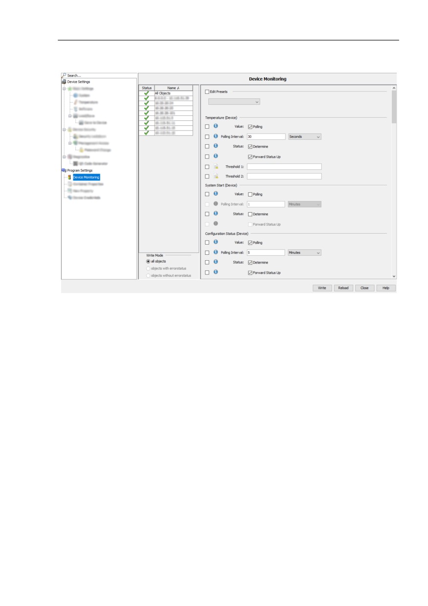
Figure 45: MultiConfig™ > Program Settings > Device Monitoring
191
Monitoring the network
6.2 Examples for using the MultiCon-
fig™
7
Monitoring the network
The basic settings of Industrial HiVision enable you to begin monitoring your
network immediately after you set up the network plan.
Important components for modifying the settings relating to the network
monitoring are contained in the following list:
Security-relevant settings
Status configuration
Status determination
Trap target address
Status forwarding
Event actions
History
You can find an overview of the monitored components under “Monitor” on
page 304.
You can find settings for monitoring the properties of a folder/device, a
component or a connection in the chapters:
“Properties of a folder/device” on page 276
“Properties of a connection” on page 290
“Properties of a component detail” on page 283
193
Monitoring the network
7.1 Improving security on the network
7.1
Improving security on the
network
An IT network offers many attack targets for uninvited intruders.
Awareness of potential security vulnerabilities and consistent closing of
these security gaps enhance the security of your network.
Industrial HiVision gives you a convenient approach to configuring security-
relevant settings.
The following sections show you step-by-step details how Industrial HiVision
helps you to improve the security of your network.
7.1.1
Password-protecting devices on your
network
Configurable network switching devices such as hubs, switches, routers,
firewalls, and wireless access points are attack targets for potentially causing
damage to your network.
To make it more difficult to access network switching equipment
management features, assign effective passwords to these devices.
Industrial HiVision gives you a multiple configuration feature that lets you
assign the same password to multiple devices in a single step. But keep in
mind that access protection improves with each individually assigned
password.
Assign new passwords to these devices periodically. Select effective
passwords.
194
Monitoring the network
7.1 Improving security on the network
7.1.2
Password change during first time log on
To help prevent undesired access, it is crucial that you change the default
password during the initial login.
Starting with the following software releases, it is necessary to change the
default password during the initial login:
HiOS
07.1.00
08.1.00
Classic
09.0.17
09.1.00
RSB
05.4.00
HiSecOS
Eagle 20/30/40 03.3.00
EagleONe
05.4.00
GarrettCom
DX
DX940
4.2.0
DX940e
1.0.3
MN4
4.2.0
10RX
XRX
5.0.0
MNS
MNS-6k 5.1.0
Industrial HiVision gives you the ability to change the default password
during initial login. When you use the MultiConfig™ > Password Change,
dialog you can change the default password on several devices at the same
time.
Example configuration
In this example, you use MultiConfig™ to change the default password on
a device where it is necessary to change the default password during the
initial login.
195
Monitoring the network
7.1 Improving security on the network
The following list contains prerequisites for changing the default
password using MultiConfig™:
the device is installed in your network
the device has an IP address
you discovered the device using the “HiDiscovery Scan“ button, or
manually add the device with New > Device.
To discover devices using the “HiDiscovery Scan“ button, see
“HiDiscovery Scan” on page 438.
To add devices manually, see “Creating new devices” on page 132.
After Industrial HiVision discovers the device, Industrial HiVision displays
the device as either a ping or HiDiscovery V1 device.
The following steps guide you through a password change:
Open the “Map“ tab.
Select the newly added devices.
Right-click on a selected device.
In the drop-down list, select the MultiConfig™ option.
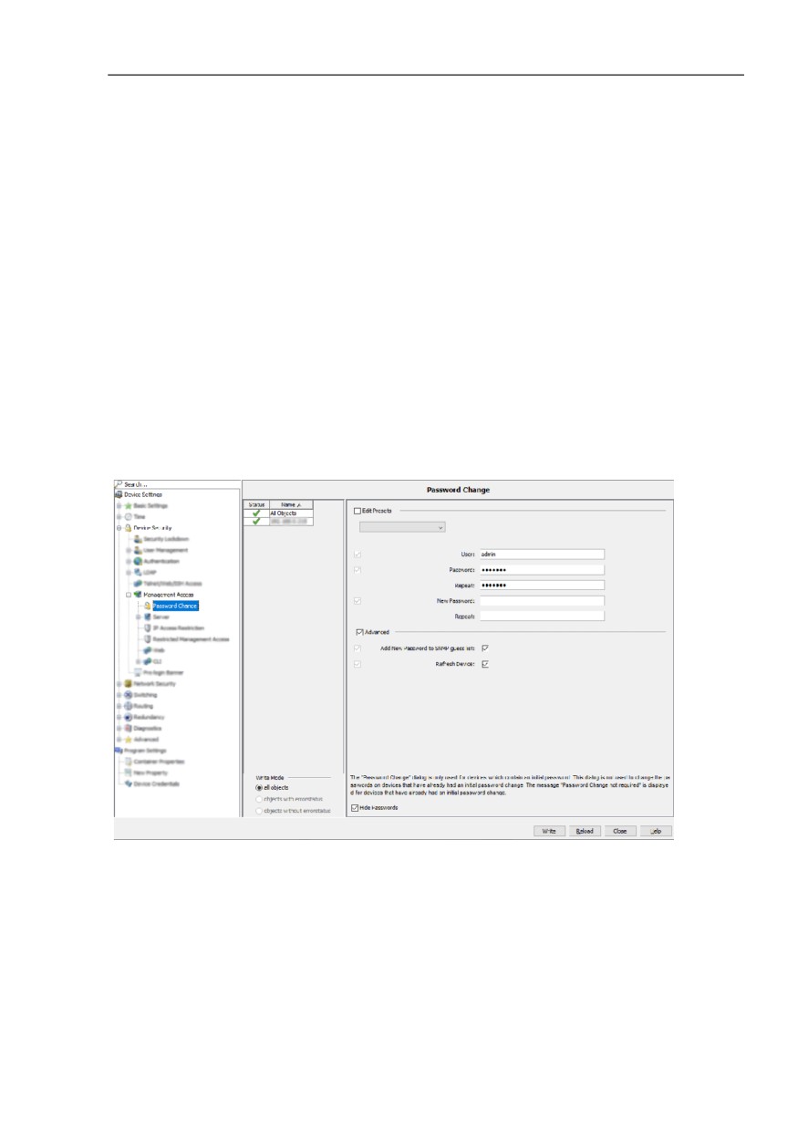
In the menu tree, select Device Settings > Device Security >
Management Access > Password Change. The “Password Change“
dialog opens.
The “User“ field contains the device default user name. Industrial
HiVision uses the value to log on the device.
The default setting for this field is admin.
The “Password“ field contains the device default password.
Industrial HiVision uses the value to log on the device.
The default setting for this field is private.
Type in the password that you wish to use for future access in the
“New Password“ field.
The default setting for this field is empty.
Confirm your new password in the “Repeat“ field.
To upload the configuration to the device, click the “Write“ button.
196
Monitoring the network
7.1 Improving security on the network
When you mark the “Advanced“ checkbox, the “Advanced“ frame
expands where you can change other values. The settings in the
“Advanced“ frame take effect after you click the “Write“ button.
When you mark, the “Add New Password to SNMP guess list“
checkbox Industrial HiVision adds the values in the “User“ and “New
Password“ fields to the Preferences > Advanced > Device
Credentials > SNMP Guess List.
The default setting for this checkbox is marked.
When you mark the “Refresh Device“ checkbox, Industrial HiVision
reloads the device.
The default setting for this checkbox is marked.
When you mark, the “Hide Passwords“ checkbox, Industrial HiVision
hides or displays the passwords in plain text. This checkbox only hides
or displays the passwords in the “Password Change“ dialog.
The default setting for this checkbox is marked.
197

Monitoring the network
7.1 Improving security on the network
7.1.3
Security status view and configuration
Security Status
In the “Security Status“ dialog, Industrial HiVision provides an overview of
the security properties of the devices in the selected folders.
The “Status“ column displays the critical condition of a property in this line.
The symbols have the following meanings:
this property was not queried
the results of querying this property comply with the general
security policies
the results of querying this property infringe on general security
policies. Please check the settings against your general security
policies.
“-” means, that the device does not possess this function.
To configure the properties that you want Industrial HiVision to monitor,
make selections in the “Configure Monitoring“ table.
The selected properties are displayed in the Status column.
The properties of the following columns can be found dependent on the
device in the device sub-folder “Security“ for the respective devices:
“Tftp“
“Profinet IO“
“IEC61850“
“Inbound ANY Rule“
“Outbound ANY Rule“
“Time Synchronization“
“Telnet“
“HiDiscovery“
“Http“
“802.1X Port Access Control Enabled“
“Restricted Management Access“
“Ethernet/IP“
“SNMP V1/V2“
“Unused Active Ports“
“Default Password“
Industrial HiVision queries these properties periodically (default setting:
24 hours). To instantly import the values into Industrial HiVision, click the
“Refresh“ button.
198
Monitoring the network
7.1 Improving security on the network
In order to increase the security of your network, the MultiConfig™
function gives you the option of changing several properties with the
warning status with one operation.
Highlight the device rows in the table, where you want to perform
changes and right click MultiConfig™.
The “Security Lockdown“ dialog under “Device Security“ enables you
to carry out several security settings at once.
To check the affected settings in the “Security Status“ dialog, refresh
the display by clicking on the “Refresh“ button. The altered properties
now display the secure status
The “Security Status“ tab only displays the operational status of the
security functions contained on a device. When you activate the security
functions on the devices, you make the network as secure as possible
with the available device functions. Missing or out-dated security
functions on the network devices can allow an intruder to access your
network. Verify that your network devices are up-to-date and that you
have configured the functions in accordance with your security definitions.
Some firmware variants do not support every security function listed in the
table. Since you cannot enable a missing function, the table displays the
missing functions as unsecure.
199
Monitoring the network
7.1 Improving security on the network
Inbound ANY Rule and Outbound ANY Rule
When the “Packet Filter” function is enabled on a device, then Industrial
HiVision examines the contents of the rules and displays the results in the
“Security Status“ dialog.
The separation of inbound and outbound statuses is accomplished by
inspecting the rule assignments on the interfaces. The default policy is
also verified. If no rule applies, then the default policy determines how the
firewall handles the data packets. If the default “Action“ policy is specified
as “Accept“, then the status is Unsecure. To determine the status
displayed in the “Inbound ANY Rule“ and “Outbound ANY Rule“ column,
Industrial HiVision also searches the following fields for an “any”
statement:
EagleOne and and EAGLE 20/30/40:
Industrial HiVision searches the following L3 firewall rules for an “any”
statement:
“Source IP (CIDR)“ = “any“
“Destination IP (CIDR)“ = “any“
“Source Port“ = “any“
“Destination Port“ = “any“
“Protocol“ = “any“
Industrial HiVision searches the following L2 firewall rules for an “any”
statement:
“Source IP (CIDR)“ = “any“
“Destination IP (CIDR)“ = “any“
“Protocol“ = “any“
For the rest of device families supported by Industrial HiVision, the
“Inbound ANY Rule“ and “Outbound ANY Rule“ default status is
considered SECURE.
Time Synchronization
Industrial HiVision verifies the clock synchronization status of each device
in your network. The following list describes the configurations that cause
the devices to display a warning in the “Time Synchronization“ column.
On Classic devices the “Time Synchronization“ column displays a
warning if SNTP and PTP are both unsecure:
If the device is configured as follows, then SNTP is unsecure:
- operation off
- operation on + client off
200
Monitoring the network
7.1 Improving security on the network
- operation on + client on + accepts broadcast on
- operation on + client on + accepts broadcast off + not synchronized
If the device is configured as follows, then PTP is unsecure:
- operation off
- operation on + not synchronized
On HiOS devices the “Time Synchronization“ column displays a warning
if SNTP and PTP are both unsecure:
If the device is configured as follows, then SNTP is unsecure:
- client off
- operation on + client on + broadcast mode
- operation on + client on + unicast mode + not synchronized
If the device is configured as follows, then PTP is unsecure:
- operation off
- operation on + not synchronized
On HiSecOS devices the “Time Synchronization“ column displays a
warning if SNTP and NTP are both unsecure:
If the device is configured as follows, then SNTP is unsecure:
- operation off
- operation on + accepts broadcast on
- operation on + accepts broadcast off + not synchronized
If the device is configured as follows, then NTP is unsecure:
- operation off
- operation on + sever mode
- operation on + client-broadcast mode
- operation on + active symmetric mode + not synchronized
- operation on + passive symmetric mode + not synchronized
- operation on + client mode + not synchronized
- operation on + client-server mode + not synchronized
On HiSecOS devices the “Time Synchronization“ column displays a
warning if NTP is unsecure:
If the device is configured as follows, then NTP is unsecure:
- Client off
- Client on + broadcast mode
- Client on + unicast mode + not synchronized
201
Monitoring the network
7.1 Improving security on the network
7.1.4
Security-related settings of devices on the
network
Disabling HiDiscovery V1
The HiDiscovery V1 protocol uses Ethernet to give you the ability to
assign a device, a device name and IP parameters. To keep this
assignment as easy as possible, HiDiscovery V1 does not include a
mechanism to limit access to the devices.
Note: When you have the HiDiscovery V1 function enabled on a device,
the “Security Status“ tab displays the device and function as unsecure.
To limit access and modifications to the IP parameters and devices
names of the devices on your network, disable HiDiscovery V1 on the
devices as soon as you finish device configurations.
The MultiConfig™ function lets you deactivate HiDiscovery V1 on
several devices in a single step.
- Highlight several devices.
- Right-click on a highlighted device and select the MultiConfig™
option from the drop-down list.
- Open the Under Device Settings > Basic Settings > Network >
Global dialog.
To disable HiDiscovery V1 on Classic devices, in the “HiDiscovery
Access“ drop-down list, select the “Disable“ option.
To disable HiDiscovery V1 on HiOS devices, unmark the
“HiDiscovery Enable“ checkbox.
Note: The checkbox on the left side of the function names only displays
a change to the function.
Configuration signature check
Classic devices from Hirschmann supply device configurations with an
individual configuration signature.
HiOS devices from Hirschmann provide device configurations with an
individual fingerprint.
The configuration signature changes every time you save a configuration
on the device, even if the existing configuration remains the same.
202
Monitoring the network
7.1 Improving security on the network
The fingerprint changes when you save a configuration on the device and
the existing configuration is altered.
The device saves the randomly generated configuration signature /
fingerprint together with the configuration.
Industrial HiVision allows you to monitor the configuration signature /
fingerprint. You are consequently in the picture if someone changes the
configuration of a device.
To select the devices with a configuration signature / fingerprint, open
to the detail view in the “Properties“ tab. Use the “Property:“ drop-down
list to select the "Configuration Signature (Device)" option.
Highlight the devices in the table, where you want to monitor the
configuration signature / fingerprint.
Right-click on the device and select MultiConfig™.
In the MultiConfig™ menu tree, click the “Status Config“ option.
In the MultiConfig™ function frame, click the “Set current to reference“
option.
In the “Reference Value“ frame, select the status, which the property
is supposed to adopt, if a current value is different from the reference
value.
To adopt the current configuration signature / fingerprint as a
reference in Industrial HiVision click the “Write“ button.
Port Security
The port security feature allows you to specify, which device is permitted
to send data to this port. Thus enabling you to block the receipt of data
from other devices.
The MultiConfig™ dialog from Industrial HiVision provides support while
configuring the port security feature of Classic devices.
Loading device certificates / keys
When you want to communicate with a device, in some circumstances
you want to know whether you are really communicating with the genuine
device. Certificates exist to verify the authenticity of devices.
Certification Authorities (CA) provide such certificates for example,
Verisign, Symantic. Some companies maintain their own institution with a
separate server, which issues proprietary certificates.
Industrial HiVision allows you, using the MultiConfig™ dialog, the
opportunity to upload certificates to devices.
203
Monitoring the network
7.1 Improving security on the network
Using a separate certificate for each device, provides you with greater
security than if you were to use one certificate for several devices.
In the “Map“ tab, right-click on the device whose certificate you want to
upload to the device and select MultiConfig™.
In the menu tree of the MultiConfig™ dialog, you can find the dialogs
for uploading the certificates/keys under Device Settings > Device
Security > Management Access > Server.
7.1.5
Configuring security-relevant settings on
the network
Security Lockdown
The “Security Lockdown“ function (access restrictions) gives you the
ability to apply security features that already exist on Hirschmann devices
at the push of a button on the managed or selected devices.
The degree of restriction is oriented on the current conditions in the
network. In other words, current network operations are maintained, but
additional access are restricted.
The “Security Lockdown“ function includes the following security
functions, assuming the devices support the functions:
Restricted management access
Industrial HiVision restricts management access to the devices on the
network management station. In as-delivered condition, any IP
address is open to access.
Port security
Industrial HiVision enables the port security feature on ports
associated with a MAC address.
If the MAC address is invalid for a connection for example, due to a
timeout, the device performs a selectable and configurable action.
Such an action could for example, send a trap to the network
management station.
This function is disabled in as-delivered condition.
204
Monitoring the network
7.1 Improving security on the network
Port security action
If the device detects an unauthorized access attempt, the device
performs the action that you configured previously.
The possible actions are:
- Do nothing
- Disable port
- Send trap
- Disable port and send trap
Disable unused ports
Industrial HiVision disables the unused ports on a device.
Disable unused slots
Industrial HiVision disables those slots of a modular device on which
the device does not discover a module.
Disable unsecure protocols
Various protocols are used to access devices on the network for
management. Industrial HiVision disables the protocols that are
considered to be unsecure. Protocols considered to be unsecure
include: HTTP, Telnet, SNMPv1, SNMPv2, HiDiscovery V1. The
SNMPv3 function is maintained.
The MultiConfig™ feature gives you the ability to configure the “Security
Lockdown“ function for several devices together in a single step.
To access the “Security Lockdown“ dialog, open the “Devices“ tab in
the detail view.
Select the devices to configure.
To open the MultiConfig™ dialog, right-click on a selected device and
click the MultiConfig™ option.
To open the “Security Lockdown“ dialog, select Device Settings >
Device Security > Security Lockdown in the MultiConfig™ dialog.
The “Security Lockdown“ function has the following restrictions:
The “Port Security“ function is unavailable for the Eagle and BAT
devices.
The “Disable Unused Slots“ function is only available for the modular
Classic and HiOS devices.
The “Disable Unused Slots“ function is only available function for the
GarrettCom RX10 devices.
The “Restricted Management Access“, and “Disable HiDiscovery“
functions are available for the following devices:
- The Classic devices starting with Version 09.0.01
- The HiOS devices starting with Version 06.0.00
- The HiSecOS devices starting with Version 03.0.00
205
Monitoring the network
7.1 Improving security on the network
Comparing IP/MAC address pairs
Attackers often use their own devices to gain access to your data network.
To do this, the attacker uses the IP address of an existing device that is
currently switched off, or a free IP address on the subnet they want to
access.
However, the MAC address of the attacker's own device can differ from
the MAC address on the device whose IP address the attacker is
spoofing.
Industrial HiVision gives you the ability to track down this kind of attacker
with the help of this feature.
To do this, Industrial HiVision collects the IP/MAC address pairs of the
connected devices. Industrial HiVision lists the IP/MAC address pairs it
collected in a table. You can manually extend this table with user-defined
entries.
Industrial HiVision gives you the ability to automate the process of
regularly checking the content of this table against the live IP/MAC
address pairs on your network. If Industrial HiVision detects a difference,
Industrial HiVision notifies you in line with the action you defined.
Make the relevant settings in order to monitor the IP/MAC address
pairs.
See “MAC/IP Address Pair Security” on page 412.
Detecting rogue devices
A rogue device is a device accessing a part of the network where it does
not belong.
Let's assume that you completed the configuration of your data network
in Industrial HiVision, and Industrial HiVision has the valid topology for
your devices and device connections. This is the right time to freeze this
state in Industrial HiVision.
Industrial HiVision then gives you the ability to reference the frozen state
and identify intruders on your data network.
When you activate this function, Industrial HiVision stores an image of the
topology.
206
Monitoring the network
7.1 Improving security on the network
But how do you deal with new devices on your data network beyond the
existing installation? These new devices could pose a potential risk to
your data network. This is why the “Rogue Device Detection“ function has
a special procedure for these devices.
After initially setting up Industrial HiVision, activate the “Rogue Device
Detection“ feature under Configuration > Preferences > Basics >
Discover Devices > Discovery Mode.
- Industrial HiVision lists any newly detected devices in the “Rogue
Devices“ folder. Since you consciously enter manually created
devices in a certain folder, Industrial HiVision leaves manually
created devices in the relevant folder.
- When Industrial HiVision lists a new device in the “Rogue Devices“
folder, Industrial HiVision generates both a “New device detected”
event and a “Rogue Device Detection“ event.
You can use “Event Actions“, or “User defined Actions“, to define how
Industrial HiVision should react to a new device displayed in the
“Rogue Devices“ folder.
207
Monitoring the network
7.2 Status configuration
7.2
Status configuration
The status configuration specifies which status is assigned to the value of the
component detail. Possible statuses are:
“No Status“
“Not Available“
“OK“
“Warning“
“Error“
Example:
You can assign the status “OK“, “Warning“ or the status “Error“ to a
connection break.
In the case of a terminal device that you regularly turn off, a connection break
(= device switched off) is not an error.
In the case of a server that should be available, a connection break is a
serious error that should be monitored.
Industrial HiVision allows you to perform the status configuration of a
component detail device overlapping for the devices in a device class (see
on page 403 “Status Configuration”).
If you want to change the status configuration of individual devices, you can
find access to the status configuration in the Properties window of a
component detail. The status configuration allows you to enter status
configuration settings for each component detail (see on page 283
“Properties of a component detail”).
A pre-condition for determining a status is monitoring a component detail.
When it monitors a component detail, Industrial HiVision queries the value
periodically. Industrial HiVision assigns a status to this value as part of the
determination.
In the state on delivery, the status configurations are set so that you can
monitor your network properly right after the installation.
208
Monitoring the network
7.3 Status determination
7.3
Status determination
To monitor your network, your network management station requires
information from the components of the network. To acquire this information,
the network management station can query the components periodically
or
the components send information (traps) on their own initiative to the
network management station.
Note: When router interfaces are active in combination with a stateful
inspection firewall, no SNMP communication is possible between Industrial
HiVision and the agent of a Classic device.
The Classic agent answers SNMP request with the IP address of the router
interface that is closest to the Industrial HiVision management station. If you
specify an IP address other than the router interface closest to Industrial
HiVision, then the destination IP address of the Industrial HiVision SNMP
packets differs to the source IP address of the SNMP packets coming from
the device agent.
If you use a firewall that does not have the right rule set for this type of
communication it can drop the packets resulting in a loss of communication
between Industrial HiVision and the device agent. For detailed information
about using firewalls with Industrial HiVision (see on page 62 “Using
Industrial HiVision with Firewalls”)
Periodic querying (polling)
Depending on the size of the network and the querying frequency,
periodic querying can lead to significant loss of available bandwidth.
In the case of, for example, short-term overloading of the network, an
answer or a trap can get lost. An advantage of periodic querying is the
high probability that the network management station receives an answer
when it makes the next query.
209
Monitoring the network
7.3 Status determination
Traps
As soon as a device detects a status change, it sends an alarm message
(trap) to the network management station. Since the device only sends a
trap if there has been a status change, this method has little effect on the
network load. However, if a packet gets lost, the network management
station may not be informed of the status change.
7.3.1
Trap destination address
To send alarm messages, a device needs the IP address (= trap destination
address) of the network management station, to which it sends any alarm
messages that arise. You can enter the trap destination address directly on
the device using, for example, the Web-based interface, or more
straightforwardly using Industrial HiVision (see on page 416 “Trap
Destination”).
Right-click on the device and select “Trap Destination“ in the drop-down
list. The trap configuration dialog opens.
Mark the “Send Traps“ checkbox.
Click the “Write“ button.
7.3.2
Updating device status
Industrial HiVision displays the status that the device had at the time of the
device detection, or the status from the received traps or status queries.
“Refresh“ allows you to read in the properties again.
210
Monitoring the network
7.4 Status propagation
7.4
Status propagation
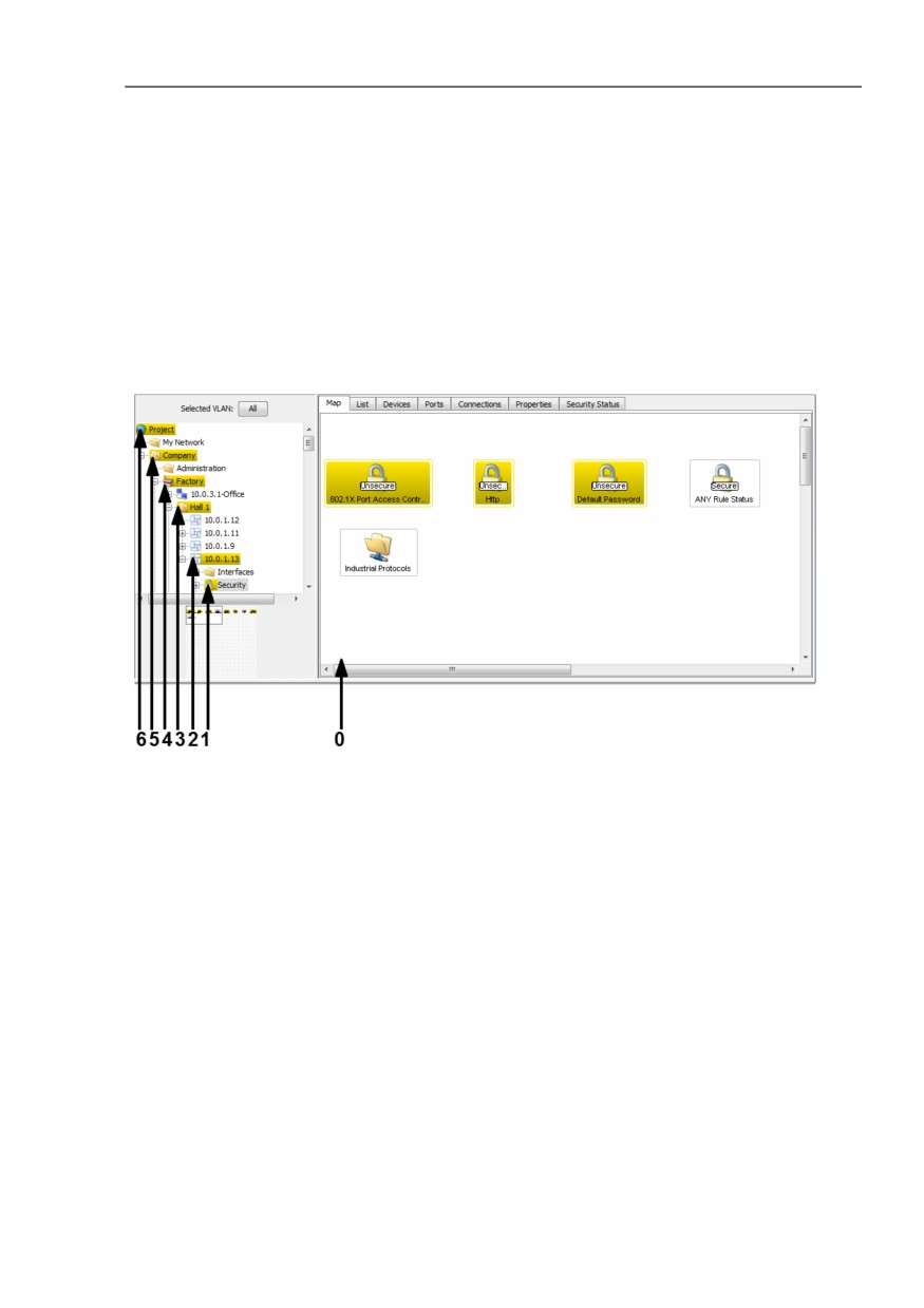
The status propagation specifies whether the status is propagated to the next
highest level.
Figure 46: Status propagation to a higher level
0 - Lowest level = component detail
1 - 1. higher level
2 - 2. higher level
3 - 3. higher level
4 - 4. higher level
5 - 5. higher level
6 - 6. higher level
211
Monitoring the network
7.4 Status propagation
A folder takes the worst status that the content of a component displays. The
evaluation is based on the following sequence:
“Error“ (worst status)
“Warning“
“OK“
“Not Available“
“No Status“
You specify the meaning of the color assignment at Configuration >
Preferences > Display > Status Colors.
In the properties window of the relevant component, you specify the
determination of the status and the propagation. The component can also
be a folder in the folder frame.
212
Monitoring the network
7.5 Management actions
7.5
Management actions
In addition to passive observation of the network, network monitoring also
consists of active intervention into network events. Active intervention
manifests itself in the response to events in the network or administrative
actions such as switching ports on and off according to a schedule.
7.5.1
Event actions
Industrial HiVision allows you to react automatically to events such as a
status change.
Select Configuration > Preferences > Basics > Event Actions
or click “Preferences“ in the tool bar and select Basics > Event Actions.
The automatic reaction options (see on page 334 “Event Actions”) provided
by Industrial HiVision are:
“Popup Message Box“
“Send SMS“
“Send E-Mail“
“Run Executable“
“Play Sound“
“Push Notification“
In the second frame of this dialog, Industrial HiVision enables you to assign
a selected reaction to an event.
Note: If you configure Industrial HiVision to run an executable file as an event
action and you get an error message, then refer to the kernel log for more
information about the error.
213
Monitoring the network
7.5 Management actions
7.5.2
Time-linked actions
Industrial HiVision offers you the opportunity to set a time period during which
Industrial HiVision responds to an event with an action.
Select Configuration > Preferences > Basics > Event Actions
or click “Preferences“ in the tool bar and select Basics > Event Actions.
Create a new entry in “Alarms“.
The “Time“ frame in the “Alarms“ dialog gives you the option of defining a
fixed period with a fixed start and end point.
7.5.3
Industrial HiVision “I'm alive” event
Industrial HiVision enables you to receive an “I'm alive” event from Industrial
HiVision when using remote monitoring.
Select Configuration > Preferences > Event Actions or click
“Preferences“ in the tool bar and select Basics > Event Actions.
Define an action that Industrial HiVision is to perform as an “I'm alive”
event for example, send an SMS.
(see on page 334 “Event Actions”)
Define an alarm that triggers Industrial HiVision to perform the action.
(see on page 334 “Event Actions”)
214
Monitoring the network
7.6 Time-related recordings
7.6
Time-related recordings
Industrial HiVision allows you to record time-related values from properties in
various databases:
in a project database (history)
in a separate report database (report)
With the size of a database the access time for the database increases.
For this reason, Industrial HiVision restricts the number of history entries that
can be recorded to the project database.
7.6.1
History
To monitor your network over a user-specified period of time, Industrial
HiVision allows you to log states with time information.
You can find settings for logging and displaying the history in the properties
dialogs
-
“Properties of a connection” on page 290 and
–
“Properties of a component detail” on page 283.
Protocol Configuration
The “Properties“ dialog of a component detail and the connection dialog
of a “Connection“ enable you:
to switch on the protocoling of the history
to enter the recording/querying interval
to enter the maximum number of entries recorded. When the
maximum number of entries is reached, Industrial HiVision throws out
the oldest entry when a new one is recorded.
100 entries (= default setting) take up approx. 5 kB of your hard
disk capacity.
215
Monitoring the network
7.6 Time-related recordings
Network load
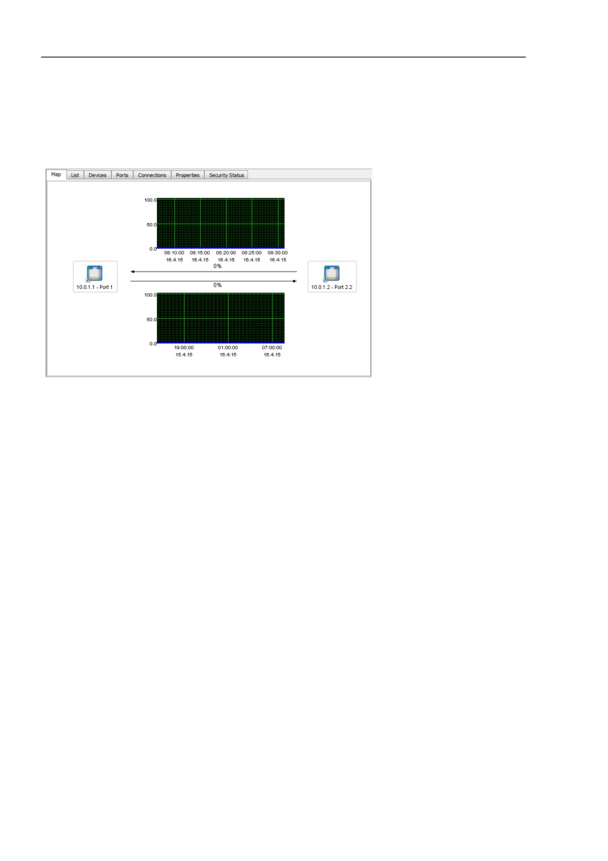
Double-click on a link to open the history window. There you can find for
each data direction a graphic representation of the network load.
Figure 47: Network load
If no ports are assigned to the link yet, you can double-click on the link to
open the dialog for assigning the ports.
If you activated polling of the threshold values in the “Properties“ dialog of
a link, then the graphic displays the threshold lines.
7.6.2
Reports
The reporting function allows you to manage long-term statistics outside the
database of the network management system program.
Industrial HiVision stores values from properties with time information in a
special report database.
To evaluate the recorded values, the reporting function allows you to output
reports in the form of graphics and tables.
216

Monitoring the network
7.6 Time-related recordings
Note: Depending on your settings, Industrial HiVision can collect any amount
of data and save it on your hard drive. Make sure that your hard drive has
sufficient free memory space.
Application example for temperature monitoring
You want to monitor the temperature fluctuation within a switch over the
course of a 5-day work week for a period of several weeks. Industrial
HiVision should generate a report for each week. You would like to have
the first report on Sunday, October 7, 2012 and further reports at weekly
intervals.
Add the temperature property to reporting:
To go to the properties level, double-click on the desired device in the
“Map“ tab.
Right-click on the icon for the “Temperature“ property. Select “Add to
Reporting...“.
Industrial HiVision opens a dialog for entering the reporting parameter.
Enter October 1, 2012, 12:00 am as the recording start time.
Press the Enter key to close the date dialog.
Set the recording start time no later than the time at which the report
requires the first entry.
Retain “Indefinite“ as the recording stop time.
Choose a polling interval as large as possible, but short enough that
Industrial HiVision is able to record the expected fluctuations.
Enter 10 minutes as the “Polling Interval“.
Click the “OK“ button.
Create a template for the report:
A template defines the appearance of the report to be generated. In this
example you want the report to be a line graph in a PDF file.
Select Configuration > Reporting in the menu bar.
In the “Reporting“ dialog, open the “Templates“ tab.
To create a new template for your report, click the “New“ button.
Enter the parameters for the template (see table 19):
Click the “OK“ button.
Parameter
Meaning
Report
Name
Temp. SW1
Title
Temperature fluctuation in switch 1
Table 19: Defining a new template
217

Monitoring the network
7.6 Time-related recordings
Parameter
Meaning
Report Type
Type
PDF
Layout
Chart
Chart Type
Line
Data
Monitored Properties
Select the property and click the right arrow button.
Table 19: Defining a new template
Create scheduling for the report:
With the scheduling function, you define the points in time at which you
want Industrial HiVision to create reports as well as the time period the
report should cover.
In the menu bar select Configuration > Reporting.
In the “Reporting“ dialog, open the “Scheduling“ tab.
To create a new schedule for your report, click the “New“ button.
Enter the parameters for the template (see table 20):
Click the “OK“ button.
Parameter
Meaning
Report
Name
Temp. SW1
Relative
This type of scheduling generates successive reports.
Duration
5 days
Offset to execution
6 days, as you want the report to include data from Monday
through Friday and the first generation of the report is to take place
on Saturday.
First Execution
Sunday, 7 October 2012, 00:00:00 am CET
Schedule every
1 week
Table 20: Defining a new schedule
218
Monitoring the network
7.7 User-defined properties
7.7
User-defined properties
To use this function you require advanced knowledge of SNMP MIB and the
device.
7.7.1
Description of user-defined properties
In the default setting, Industrial HiVision already recognizes a large number
of devices and their properties.
With the “User defined Properties“ function, Industrial HiVision allows you to
include additional properties from the MIB of SNMP-capable devices in the
management.
In this way you can add and monitor the properties of any SNMP-capable
devices in Industrial HiVision. You can also add additional properties from
MIB to devices already recognized by Industrial HiVision and monitor them.
7.7.2
Application example for user-defined
properties
In a sensitive network, you want to use ICMP packets to monitor the load on
the network components. If a device receives more than 10 ICMP requests
within 5 minutes, you want Industrial HiVision to send a warning.
To inform Industrial HiVision about this new property, you select the
Configuration > User defined Properties dialog.
To create a new entry with a new property, in the “User defined
Properties“ dialog, click the “New“ button.
219
Monitoring the network
7.7 User-defined properties
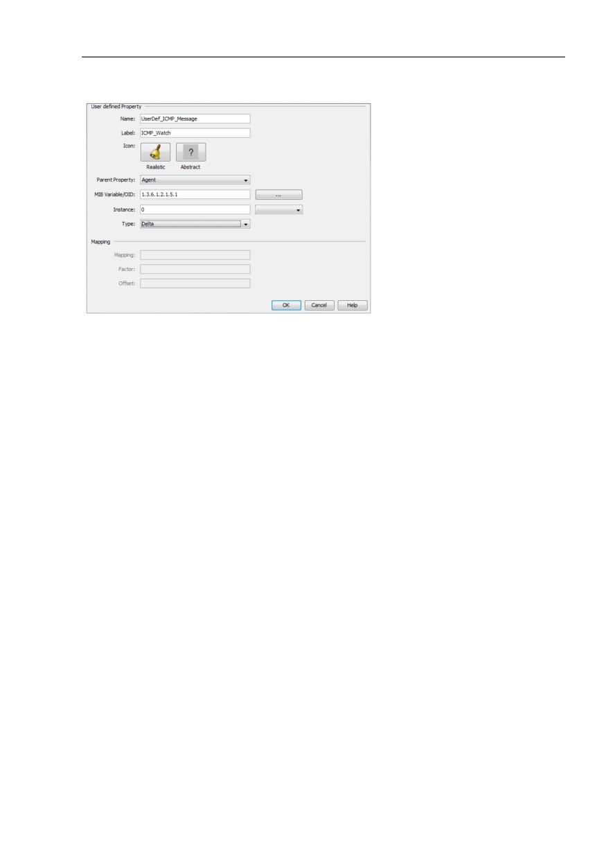
In the “Name“ field, give the new property a unique name for example,
UserDef_ICMP-Message. Here Industrial HiVision expects a name that
starts with “UserDef_“.
In the “Label“ field, enter an identifier for this property that Industrial
HiVision displays in the user interface for example, ICMP-Watch.
In the “Parent Property“ drop-down list select, “Agent“.
In the “MIB Variable/OID“ field, enter the MIB variable of the new property.
Alternatively, the MIB Manager allows you to search for the MIB variables
in the MIB of the device:
- To open the MIB Viewer, click the “...” button.
- To get an overview of the MIBs that the “MIB Viewer“ has loaded, click
the “MIB Manager“ button.
Industrial HiVision also allows you to load additional MIBs into the MIB
Viewer, click the “Load...“ button. Then select the desired MIB from
your file system.
- Open the path iso:org:dod:internet:mgmt:mib-2:icmp.
- Select the MIB variable icmpInMsgs.
- To close the “MIB Viewer“, click the “OK“ button.
In the “Instance“ field, enter the instance of the MIB variables, in this
case 0.
In the “Type“ drop-down list, select, “Delta“.
220
Monitoring the network
7.7 User-defined properties
Figure 48: Creating a new user-defined property
To finish defining the property, click the “OK“ button.
You can now see the new defined property in the “User defined
Properties“ window.
To close the “User defined Properties“ window, click the “OK“ button.
Now go to the list view from the detail display.
In the list view, select the agent of the device that you want to monitor.
To open the “New Property“ window, right-click on the list view and select
New > Property.
To close the window again, select the newly-defined property ICMP Watch
in the “New Property“ window.
Click the “OK“ button.
You have now assigned the new property ICMP Watch to the agent. To
monitor the new property of the agent, configure the status (see on page 208
“Status configuration”) and the status determination (see on page 209
“Periodic querying (polling)”).
221
Monitoring the network
7.8 Effect on system resources
7.8
Effect on system resources
Industrial HiVision provides you with a range of options for managing and
monitoring your network. This range of options also makes it possible for you
to exhaust your system resources and even to overload them.
In this chapter, you can find the following information about the utilization of
your system resources:
detect
influence
minimize
222