Network Management System Industrial HiVision 8.2. User Manual (2021) - page 6
Configuring the network
6.1 Using the dialog box
6.1.1
Description of the menu tree
In the Web-based, interface-type menu tree, you select the function that you
want to configure. Here you will find functions
- that you configure on the devices
- and properties that you configure for the monitoring in Industrial HiVision
6.1.2
Description of the object frame
The object frame contains a table of the objects that you selected for
configuration in the detail display.
In the first row of the table you will find the summary of the statuses of the
objects in the table.
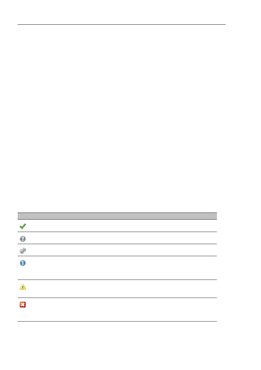
The status symbols behind the objects have the following meanings:
Symbol Meaning
Industrial HiVision has read the values of the parameters and displays the
matches in the function frame.
Action initiated but not started yet.
Industrial HiVision is reading/transferring the values of the parameters.
Move the mouse pointer over the symbol to obtain information about any
peculiarities.
A peculiarity could be, for example, that a table contains hidden entries. These
hidden table entries are lost when data is written.
Industrial HiVision can reach the device. One or more values are missing from
the transfer.
Move the mouse pointer over the symbol to obtain information.
The objects have not supplied any values.
The connection to the device is interrupted.
Move the mouse pointer over the symbol to find out the reason why you cannot
read/write the values.
Table 12: Meaning of the status symbols
160
Configuring the network
6.1 Using the dialog box
6.1.3
Description of the function frame
In the function frame, Industrial HiVision provides a selection of parameters
and actions. Industrial HiVision selects the configurable parameters and
executable actions that represent an intersection of the selected objects and
the selected function.
As the number of variations for representing the parameters is too large, you
will find additional application examples later on (see on page 164 “Examples
for using the MultiConfig™”).
You use the selection field on the left side of the function frame to select the
parameters you want to configure.
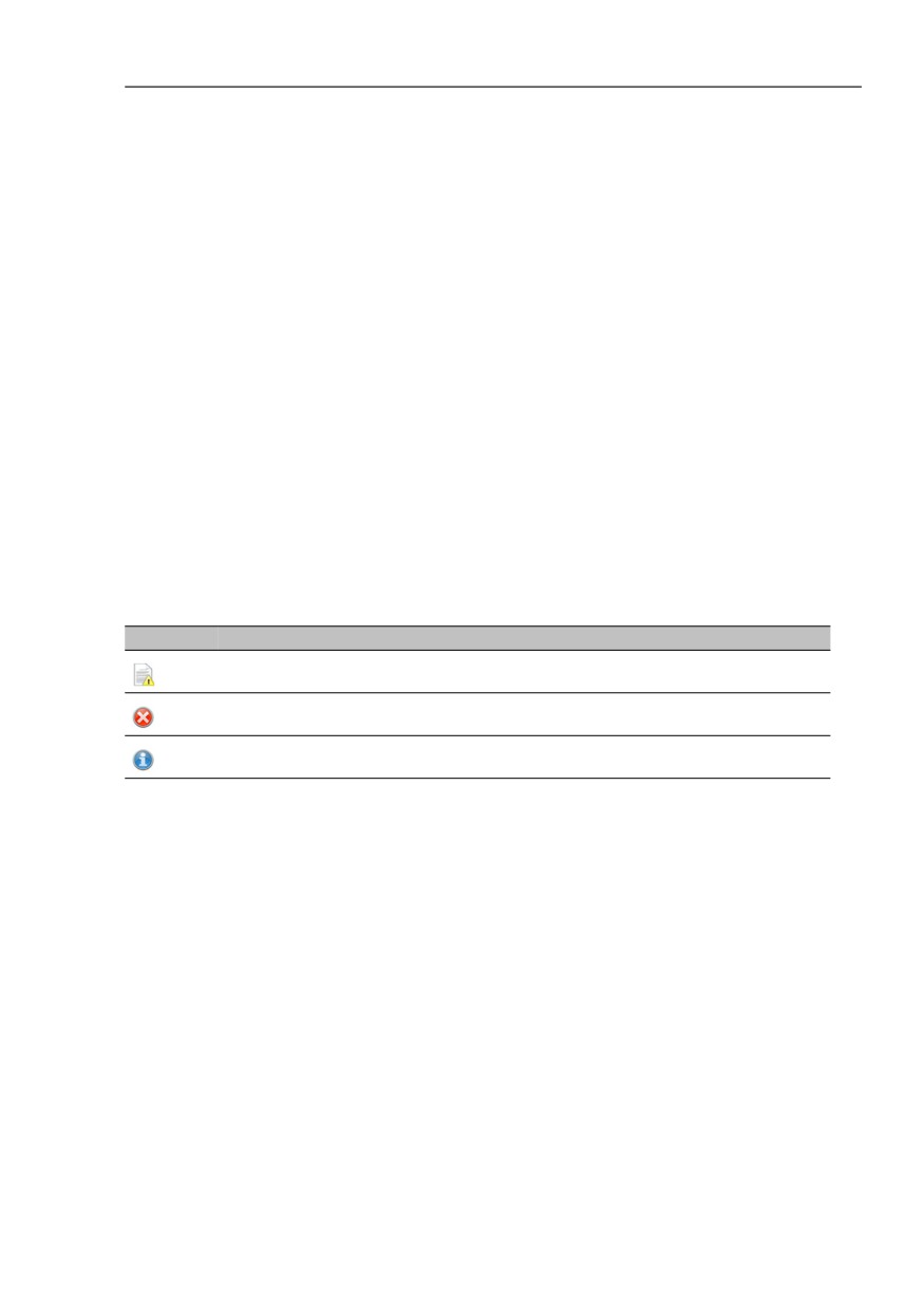
The symbols beside the selection fields, if there are any, have the following
meanings (see table 13).
Symbol Meaning
The objects read have different values for this parameter.
The object selected has no value for this parameter.
Some objects have no values for this parameter.
Table 13: Meaning of the symbol beside the selection fields
To simplify entering settings that reoccur, Industrial HiVision allows you to
create default settings (see on page 165 “Using contact person with default
setting”).
161
Configuring the network
6.1 Using the dialog box
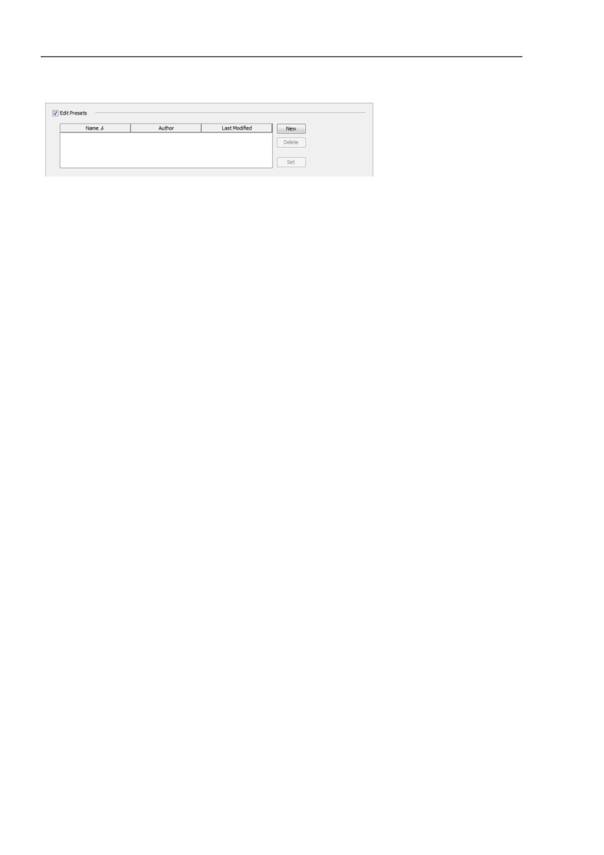
Figure 39: Default setting for the MultiConfig™ function.
Because the MultiConfig™ function provides a range of input options on
different device types, Industrial HiVision allows any values to be entered in
the input fields.
If Industrial HiVision detects an inconsistency during entry, Industrial
HiVision changes the font color to red.
To load or save files, enter a path in the respective dialogs describing the
storage location of the file. Industrial HiVision can handle absolute and
relative paths. A relative path begins with <Install-Dir>/service.
162

Configuring the network
6.1 Using the dialog box
6.1.4
Description of the control elements
“Write“
With “Write“ Industrial HiVision transfers the data for the parameters
selected to the following locations:
- every object contained in the table of the Object frame.
- the objects with an error status contained in the table of the Object
frame.
- every object without an error status contained in the table of the Object
frame.
You select the objects you want to write to in the Object frame under
“Write Mode“.
When you write configuration parameters on devices in this way, these
parameters are located in the temporary memory of the devices. To save
the device configuration data, the last configuration step you perform is to
save the new configuration on the devices.
“Reload“
With “Reload“, Industrial HiVision transfers the data in the selected
parameters from the objects contained in the table of the object frame.
To display the values of the parameters for an object, click on the object
in the object frame.
“Cancel“
With “Cancel“ Industrial HiVision closes the dialog. Changes that you
entered after the last “Write“ command are lost.
Actions that have already started
are completed by Industrial
HiVision.
“Help“
With “Help“ Industrial HiVision opens the on-line help on the relevant
page.
If an example exists for the opened dialog (see on page 164 “Examples
for using the MultiConfig™”), then Industrial HiVision opens the on-line
help on the page for the example.
163
Configuring the network
6.2 Examples for using the MultiCon-
fig™
6.2
Examples for using the
MultiConfig™
Depending on the menu item you select, you will find different
representations in the function frame. The following examples show you the
different representations.
6.2.1
Same contact person on multiple devices
You want to enter the same contact person for example, Michael, on multiple
devices.
In the detail display, open the “Map“ view or another view that displays
devices.
Select the devices on which you want to enter the same contact person.
To open the MultiConfig™ dialog, right-click on a selected device and
select “MultiConfig™”.
In the MultiConfig™ dialog, select Device Settings > Basic Settings >
System in the menu tree.
You will then find the table with the related devices in the object frame,
and the configurable parameters in the function frame.
Displaying current parameter values
To display the values of the parameters for a device, click on a row of
the table in the object frame.
To display the values of the parameters that are the same on each
device, click on the first row “All Objects“ of the table in the object
frame.
164
Configuring the network
6.2 Examples for using the MultiCon-
fig™
Writing contact persons on devices
Mark the “Contact“ checkbox.
Enter the name of the contact person for example, Michael, in the
“Contact“ text field.
To transfer the change to the devices and temporarily save them
there, click the “Write“ button.
To save the changes to the devices into the permanent memory,
select Device Settings > Basic Settings > Load/Save, in the menu
tree.
Select “Save to Device“, from the “Action“ drop-down list.
Click the “Write“ button.
Using contact person with default setting
Industrial HiVision allows you to create a name as the default setting so
that you do not have to enter the name again when configuring additional
devices later on.
Mark the “Contact“ checkbox.
Enter the name of the contact person for example, Michael, in the
“Contact“ text field.
Mark the “Edit Presets“ checkbox. Industrial HiVision now opens the
preset table.
Click the “New“ button beside the preset table to enter the selected
parameters as presets.
To give the new table entry a meaningful name, double-click the name
cell for this entry and enter the name for example, “Contact person
Michael”.
Click on the “Write“ button to take over the change.
From now on, you can select the “Contact person Michael” preset instead
of having to select and enter the name.
To change an existing table entry, select the desired row, change the
parameters, and click “Set“.
To select an object in the Object frame, deselect “Edit Presets“ in the
Function frame.
165

Configuring the network
6.2 Examples for using the MultiCon-
fig™
6.2.2
Software update on similar devices
You want to perform a software update on a number of similar devices:
In the detail display, select the “Devices“ view.
Select the Device Class.
Select the devices on which you want to perform the software update.
To open the MultiConfig™ dialog, right-click on a selected device and
select “MultiConfig™”.
In the MultiConfig™ dialog, select Device Settings > Basic Settings >
Software in the menu tree.
You will then find the table with the related devices in the object frame,
and the settings for the update in the function frame.
To open the file selection screen, click on “File“> “...” in the function
frame. Select the software update file or use drag & drop to pull it into the
row and click the “Open” button.
Mark the “Update“ and “File“ checkboxes.
Click the “Write“ button to transfer the update to the devices.
In the object frame, the
symbol in the “Status“ column informs you
that the transfer was successful.
To activate the new software on the devices, perform a cold start on the
devices (see on page 167 “Restarting multiple devices”).
166
Configuring the network
6.2 Examples for using the MultiCon-
fig™
6.2.3
Restarting multiple devices
With its MultiConfig™ function,Industrial HiVision offers the option of
initiating a restart on multiple devices.
Industrial HiVision distinguishes between a successive “Restart
(consecutively)“ and a concurrent “Restart (simultaneously)“.
“Restart (consecutively)“
Industrial HiVision sends a restart command to a device and waits until
the device has executed the restart. Then Industrial HiVision sends the
restart command to the next device.
You select this method if the devices you want to start are connected to
the network management station in a line.
“Restart (simultaneously)“
Industrial HiVision sends the restart command to the devices to be started
nearly simultaneously. You select this method if the network management
station accesses the devices directly.
Note: Restarting a device interrupts the transfer. This means that some
devices may not receive the restart command.
In the MultiConfig™ dialog, select Device Settings > Basic Settings >
Restart (consecutively) or Device Settings > Basic Settings > Restart
(simultaneously) in the menu tree.
In the object frame, you will now find the restart options for the devices.
Mark the checkboxs for example, in the “Cold Start“ row after a software
update.
Click the “Write“ button.
167

Configuring the network
6.2 Examples for using the MultiCon-
fig™
6.2.4
Loading/saving the configuration for
multiple devices
Depending on the devices you have selected, Industrial HiVision gives you
multiple options for transferring configurations:
Action
Load/Save
Load/Save
using PC
Save on device
X
Copy the current configuration from the non-volatile memory of
the device to the permanent memory of the device.
Save on TFTP server (binary)
X
Copy the current configuration in binary form from the non-
volatile memory of the device to the specified URL.
Save on TFTP server (script)
X
Copy the current configuration as an editable and readable
script from the non-volatile memory of the device to the
specified URL.
Load from device
X
Copy the configuration from the permanent memory of the
device to the non-volatile memory of the device.
Load from TFTP server
X
Read the configuration from the specified URL to the non-
volatile memory of the device.
Load from TFTP server and save on device
X
Read the configuration from the specified URL to the non-
volatile and permanent memories of the device.
Delete: current configuration
X
Overwrite the configuration in the non-volatile memory of the
device with the configuration in the permanent memory of the
device.
Delete: current configuration and from device
X
Delete the configuration in the non-volatile memory of the
device and the configuration in the permanent memory of the
device, and replace with the configuration from the state on
delivery. After the next restart, the IP address is also in the
state on delivery.
Save on PC (script)
X
Copy the configuration as an editable and readable script from
the non-volatile memory of the device to a file on the PC.
Save on PC (binary)
X
Copy the configuration in binary form from the non-volatile
memory of the device to a file on the PC.
Table 14: Transfer options for configurations
168

Configuring the network
6.2 Examples for using the MultiCon-
fig™
Action
Load/Save
Load/Save
using PC
Load from PC (script)
X
Read the configuration from a file as an editable and readable
script from the PC to the non-volatile memory of the device.
Load from PC (binary)
X
Read the configuration from a file in binary form from the PC to
the non-volatile memory of the device.
Table 14: Transfer options for configurations
In the detail display, open the “Map“ tab or another tab that displays the
devices.
Select the devices from which you want to save a configuration, or on
which you want to load a configuration.
To open the MultiConfig™ dialog, right-click on a selected device and
select “MultiConfig™”.
Select Device Settings > Basic Settings > Load/Save in the menu
tree. You can also select Device Settings > Basic Settings > Load/
Save via PC
You can then find the table with the related devices in the object frame,
and the options for transferring the configuration in the function frame.
“Load/Save“
- For this example select, the “Load/Save via PC“ option.
- Select the desired transfer type from the “Action“ drop-down list.
- Verify that the checkbox is marked.
Mark the “File“ checkbox and enter the file name with the complete path
for example, D:\Data\Network Management\Configurations/
$CURRENT-DATE/$IP_ADDRESS.$EXTENSION or the URL tftp://
10.0.1.159/configs/2009_10_28/$IP_ADDRESS.cfg
Industrial HiVision allows you enter a file name and a URL in the settings
(see on page 397 “Load/Save”).
When writing the data, Industrial HiVision creates any subfolders that are
missing.
To transfer the data, click the “Write“ button.
In the object frame, the
symbol in the “Status“ column informs you
that the transfer was successful.
169
Configuring the network
6.2 Examples for using the MultiCon-
fig™
6.2.5
Configuring a trap destination on multiple
devices
You want to configure the same trap destination on multiple devices.
In the detail display, open the “Map“ view or another view that displays
devices.
Select the devices on which you want to configure the same trap
destination.
To open the MultiConfig™ dialog, right-click on a selected device and
select “MultiConfig™”.
In the MultiConfig™ dialog, select Device Settings > Diagnostics >
Status Config > Trap Destinations in the menu tree.
You will then find the table with the related devices in the object frame,
and the table for the trap destinations in the function frame.
To create a new entry in the table,
click “New“.
Enter the IP address of the trap destination, select the active status and
click “OK“.
In the table you will find the rows with the new trap destination.
To transfer the change to the devices and temporarily save them there,
click “Write“.
To save the change on the devices into the permanent memory, select
Device Settings > Basic Settings > Load/Save, in the menu tree,
select the action “Save to Device“ and click the “Write“ button.
6.2.6
Make firewall rules on multiple devices
You can use the MultiConfig™ dialog to specify firewall rules. The
MultiConfig™ dialog also lets you save the presets for the firewall rules, then
upload the firewall rules on other EagleOne devices.
The MultiConfig™ Firewall Rules Table
The MultiConfig™ dialog shows an index table with rows which contain
the firewall rules saved on the selected EagleOne device.
170
Configuring the network
6.2 Examples for using the MultiCon-
fig™
When you select multiple devices, the index table can show a subset of
rules on the selected EagleOne devices. The index table identifies the
subset with an “unequal” symbol. The “unequal” symbol means that the
rule is different on the selected devices. The difference for the rule can be
either information contained in the rule or sequence of the rules on each
device. If you save presets with rules identified as “unequal”, then
MultiConfig™ saves the “unequal” cell as blank. You can remove rows
which contain the blank cells or enter the necessary information.
The firewall dialogs have “Up” and “Down” arrow buttons. The arrow
buttons allow you to change the sequence of the rules in the index table.
Note: You cannot change the information in the rows identified as “not
equal”. However, you can remove the rows from the index table.
Example
The server for the virus update files requires you to release another port
in the firewalls of your company. For this, you want to add a new 1st rule
for the relevant firewalls that releases this port.
Save a new rule as a preset
In the detail display, open the “Map“ tab or another tab that shows
devices.
Right-click on the EagleOne device to which you want to add the
rule(s) and select the “MultiConfig™” function from the drop-down list.
In the menu tree of the MultiConfig™ dialog, select the relevant packet
filter.
In the function frame of the MultiConfig™ dialog, mark the “Edit
Presets“ checkbox.
To save a preset for the rules in the index table, in the “Edit Presets“
frame click the “New“ button.
Note: If you want to save the complete content of the index table as a
preset, deselect the rules in the index table. If you want to save a rule
or multiple rules as a preset, in the index table select the rule(s).
In the “Edit Presets“ table, double-click in the name cell and enter a
meaningful name for the preset.
171

Configuring the network
6.2 Examples for using the MultiCon-
fig™
After you enter the name, e.g. “Existing rule set”, click the “Set“ button
or press the “Enter” button on your keyboard.
After you save the rules as a preset, delete the rules in the index table.
In the index table, make a new rule for the port release, or if necessary,
make multiple rules.
To save the new rule or multiple rules as a preset in the Industrial
HiVision database, in the “Edit Presets“ frame click the “New“ button.
- In the “Edit Presets“ table, double-click in the name cell and enter
a meaningful name for the preset.
- After you entered the name, e.g. “Virus update”, click the “Set“
button or press the “Enter” button on your keyboard.
To restore the original rules, select the preset “Existing rules set” from
the “Edit Presets“ table.
To save the data on the device, click the “Write“ button.
In the object frame, the
symbol in the “Status“ column tells you that
MultiConfig™ saved the rules to the device.
After these actions, the firewall device is in its original state, and
MultiConfig™ saved the preset “Virus update” in Industrial HiVision.
Close the MultiConfig™ dialog.
Add a new rule to the relevant firewall devices
In the detail display, open the “Map“ tab or another tab that displays
devices.
Select the firewall devices to which you want to add this rule.
Right-click on a selected firewall device and select “MultiConfig™”.
To add the new rule for the port release as the first rule, you select the
first rule.
With the “Edit Presets“ checkbox unmarked, select the “Virus update”
preset in the drop-down list.
Industrial HiVision adds the rules with the “Virus update” preset above the
selected rule.
Note: If the rules on the devices in this dialog are identical, Industrial
HiVision allows you to add the new rules above the last rule.
To save the data on the device, click the “Write“ button.
In the object frame, the
symbol in the “Status“ column tells you that
MultiConfig™ saved the rules to the device.
Close the MultiConfig™ dialog.
172
Configuring the network
6.2 Examples for using the MultiCon-
fig™
General information for the Edit Presets table
“Edit Presets“ activated:
When the mode is active you can show and edit rules.
- To show a preset in the bottom frame, you select the preset.
- To save the rules from the bottom frame as a preset, click the
“New“ button.
- To change a preset, you select the preset from the “Edit Presets“
drop-down list. Edit the rules in the bottom frame. Confirm the
action with “Set“.
“Edit Presets“ deactivated:
When the mode is inactive, you can add rules.
- To add rules from a preset to the rules in the bottom frame, select
the row above which you want to add the rules in the bottom frame,
and select the necessary preset.
- To add rules from a preset to the end of the rules in the bottom
frame, deselect the rows in the bottom frame and select the
necessary preset.
6.2.7
Configuring the Industrial HiVision property
The availability of your transmission component has the highest priority.
Therefore, you want Industrial HiVision to keep you informed if the
redundancy of the supply voltage is missing.
In the standard status configuration of the power unit status of Industrial
HiVision
- Industrial HiVision assigns the status “OK” to the value “Not installed”.
- Industrial HiVision assigns the status “No status” to the value “Not
available”.
However, in both cases you want to receive the status “Warning”.
In the detail display, open the “Properties“ tab.
In the “Property:“ drop-down list, select the property “Status“ (“Power
Supply“).
In the table you select the power units for which you want to change the
configuration.
173
Configuring the network
6.2 Examples for using the MultiCon-
fig™
To open the MultiConfig™ dialog, right-click on a selected row and select
“MultiConfig™”.
In the MultiConfig™ dialog, select “Status Config“ in the menu tree.
You will then find the table with the related devices in the object frame,
and the options for setting the status configuration in the function frame.
Mark the following checkboxes:
-
“Value“ = “Not Installed“
–
“Value“ = “Unavailable“
In the drop-down list for the two rows, select the status “Warning“.
To save the change in Industrial HiVision, click the “Write“ button.
6.2.8
Saving reference values for each device
The MultiConfig™ function provides support when processing the same
values on several devices, and also when processing individual values for
several devices. An example can be found at “Configuration signature check”
on page 202.
6.2.9
Password synchronization
Industrial HiVision allows you to synchronize the SNMP v1/v2 passwords
with the SNMP v3 passwords. This function allows you to change the SNMP
v1/v2 passwords in various dialogs at the same time. The function is useful
in cases where the network is also monitored by another network
management system that uses only SNMP v1/v2 for device access.
The function changes the SNMP v1/v2 passwords in the following dialogs:
MultiConfig™ > Device Security > SNMP V1/V2 > Stations
MultiConfig™ > Program Settings > Device Credentials for the “V1“
settings.
174
Configuring the network
6.2 Examples for using the MultiCon-
fig™
To synchronize the passwords proceed as follows:
Verify that Industrial HiVision uses SNMP v3 to access the selected
devices.
In the MultiConfig™ device frame, highlight the uppermost device.
Open the MultiConfig™ > Program Settings > Device Credentials
dialog.
The “SNMP Version“ field displays the SNMP version used to access
the device.
Verify every device listed in the MultiConfig™ device frame.
Select the devices on which you wish to synchronize the passwords.
Right click on a selected device.
Select “MultiConfig™“ from the drop-down list.
Open the MultiConfig™ > Device Security > SNMP V3 > Password/
SNMP Access dialog.
Enter the SNMP v3 passwords in the “Read-only password (user)“ and
the “Read-write password (admin)“ fields. You can reuse the current
passwords or specify new password in the fields.
Mark the “Synchronize password to v1/v2 community“ checkbox.
Click the “Write“ button.
Note: Using the SNMP v1/v2 protocol is a security risk.
6.2.10 MultiConfig™ Search Function
The MultiConfig™ search function scans the menu tree and dialogs for a
match to the word entered in the search field. The function allows you to find
a function quickly. After you enter the first character in the search field,
Industrial HiVision begins to search the menus tree nodes and dialogs for the
character string. Industrial HiVision then displays only the menu tree nodes
and dialogs with the character string in the menu tree node name or dialog.
175
Configuring the network
6.2 Examples for using the MultiCon-
fig™
The search function may return an empty dialog or a dialog without the word
entered in the search field. The reason for this is that Industrial HiVision finds
the function in a dialog, but not every device selected has the function. If a
device, within a group of selected devices, does not have the function
containing the search word, then Industrial HiVision hides the function.
6.2.11 MultiConfig™User Management
The MultiConfig™ “User Management“ function allows you to specify user
credentials on several devices in your network at the same time. The “User
Management“ function is available only on HiOS devices.
When you edit user credentials in the “User Management“ dialog, Industrial
HiVision requires that you enter a “Password“. The reason for this is security.
Industrial HiVision does not store device passwords nor retrieve the
passwords stored on a device. The password that you enter during editing
can be a new password or if known, the current password stored on the
device for the specific user.
To modify the credentials of a user, high light the user, then click the “Edit“
button. The rules listed in the following table apply:
176

Configuring the network
6.2 Examples for using the MultiCon-
fig™
Parameter
Meaning
Access
Specifies the user with which you access the device.
Industrial HiVision allows only 1 user to have access at a
given time.
Note: The following list contains the prerequisites for
activating the access for a user:
•
Mark the “Active“ checkbox.
•
Specify a password.
•
Unmark the “User locked“ checkbox.
Username
The name of the user account.
Note: The prerequisite for modifying the user name is that
you specify a password.
Active
Activates/deactivates the user account.
Possible values:
Selected
The user account is active. Industrial HiVision uses
the credentials to log in to the device.
Not selected
The user account is inactive.
Note: The prerequisite for deactivating the user is that you
unmark the “Access“ checkbox.
Table 15: MultiConfig™“User Management“
177

Configuring the network
6.2 Examples for using the MultiCon-
fig™
Parameter
Meaning
Password
Specifies the password with which Industrial HiVision logs
in to a device.
Possible values:
6..64 alphanumeric characters
including the following special characters:
!#$%&'()*+,-./:;<=>?@[\\]^_`{}~
When you select the “Policy Check“ checkbox, the device
verifies that the password complies to the policies defined
in the Device Security > User Management > Global
dialog.
Note: Industrial HiVision prohibits the use of 2 sequential
asterisks, for example “**”.
Access Role
Specifies the access role that regulates the access to the
individual functions of a device.
Possible values:
unauthorized
The user is locked, and the device rejects the log in of
the user. You assign this value to temporarily lock a
user account.
guest
The user is only authorized to monitor the device.
auditor
The user is authorized to monitor the device and to
save the log file in the Diagnostics > Report > Audit
Trail dialog.
operator
The user is authorized to monitor and configure the
device with the exception of security settings for
device access.
administrator
The user is authorized to monitor and configure the
device.
Table 15: MultiConfig™“User Management“
178

Configuring the network
6.2 Examples for using the MultiCon-
fig™
Parameter
Meaning
User locked
Displays whether the user account is locked due to
excessive failed login attempts
Possible values:
Selected
The device automatically locked the user out due to
excessive failed login attempts.
Only the device can mark the checkbox.
Not selected
Unlocks access to the device for the user.
Note: The prerequisite to unlocking a user account is that
you log in to Industrial HiVision as an administer.
Policy Check
Specifies whether Industrial HiVision verifies if the
password is in accordance to the defined policy when it is
being configured or changed.
Possible values:
Selected
The device verifies that the password complies to the
policy defined in the User Management > Global
dialog.
Not selected
The device accepts the password without verification.
SNMP Auth Type
Specifies the authentication protocol that the device
applies for user access via SNMPv3.
Possible values:
hmacmd5
For this user account, the device uses protocol
HMAC-MD5.
hmacsha
For this user account, the device uses protocol
HMAC-SHA.
SNMP Encryption Type
Defines the encryption protocol that the device applies for
user access via SNMPv3.
Possible values:
none
No encryption
des
DES encryption
aesCfb128
AES-128 encryption
Table 15: MultiConfig™“User Management“
179
Configuring the network
6.2 Examples for using the MultiCon-
fig™
6.2.12 MultiConfig™ Time Sensitive Networking
Hirschmann devices support time-aware queuing defined in IEEE 802.1 Qbv.
This TSN feature allows the TSN-capable ports to transmit data packets of
every traffic class scheduled relative to a defined cycle, in the gate control
list. The VLAN tag of an Ethernet packet - or the port priority in case of an
untagged packet - contains the priority.
The feature helps to avoid latency and congestion loss for reserved data
streams. The precise synchronization of cycles and gate states using
IEEE1588 (PTP) allows congestion-free and thus low-latency
communication. The prerequisite is that every device in the network supports
IEEE 802.1 Qbv.
To help you monitor the TSN ports, Industrial HiVision provides a TSN widget
in the dashboard. You can find more information about the TSN widget in the
chapter titled “TSN Schedule Widget” on page 434.
You can learn more about TSN networks in the “TSN for Dummies” book
under the following URL:
networking-for-dummies-lp
TSN Example Network
It is necessary to configure some functions on the devices before you
configure the TSN schedule using MultiConfig™. To configure the
devices used in the TSN network, the prerequisites for using
MultiConfig™ are as follows:
configure the VLANs and VLAN port membership
configure the Forwarding Database for the TSN stream
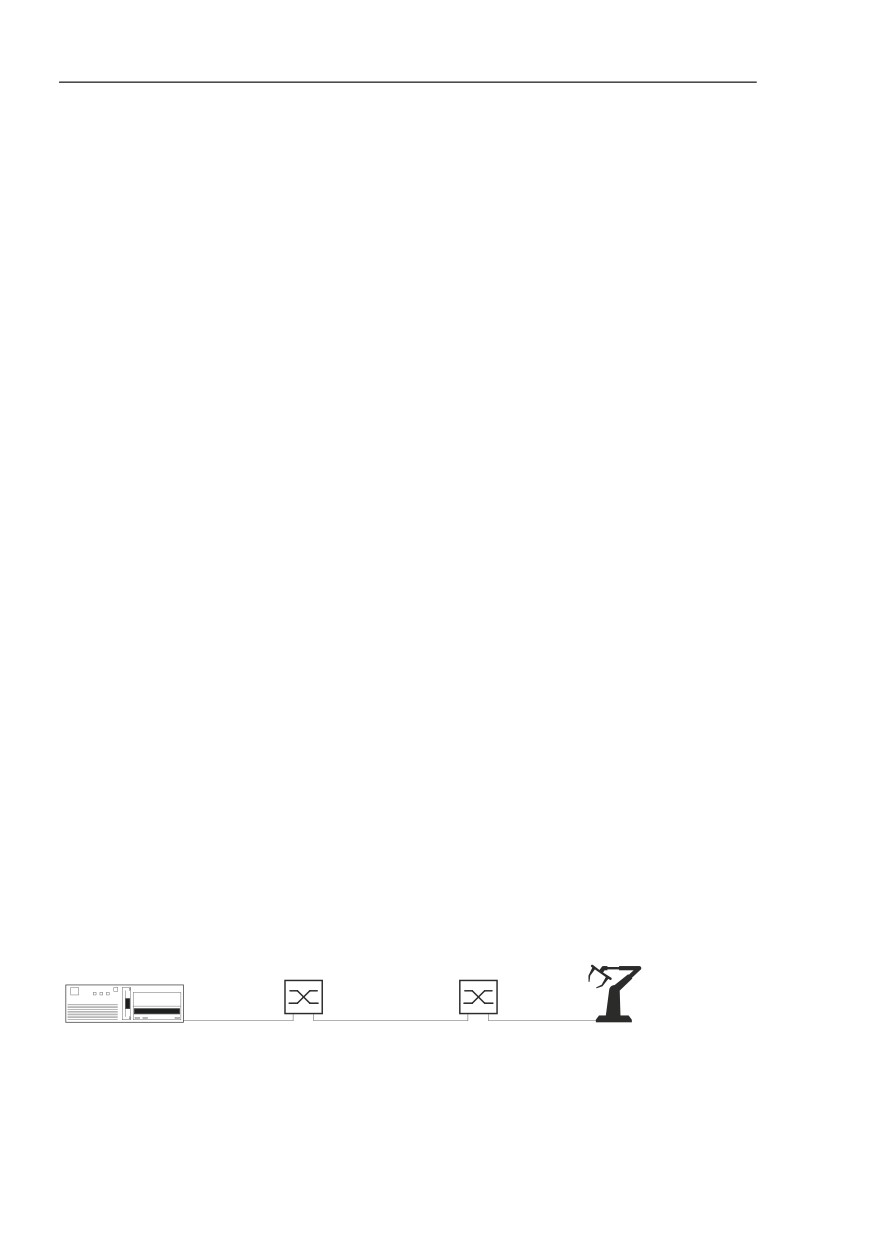
For our example, we configure a parallel network to pass a mission-critical
data stream between the end devices.
1/1
1/2
1/1
1/3
Talker
Device 1
Device 2
Listener
Figure 40: TSN network with TSN compatible devices
180
Configuring the network
6.2 Examples for using the MultiCon-
fig™
The cycle time is application specific. For our example we use the cycle
time value 1000000 ns. To configure the time-specific settings for the TSN
function, first determine and calculate the following delays.
Propagation delay depends on the cable length (approximately 5 ns/
m).
Bridge delay = Reception delay + Transmission delay
- Reception delay = Independent delay + Dependent delay of the
receiving port
- Transmission delay = Independent delay + Dependent delay of the
transmitting port
Gate open time = Propagation delay + Bridge delay
Minimal gate open duration is the duration necessary to transmit a
packet, which consists of the Service Data Unit (SDU) + 36 bytes, with
the maximum possible delay.
To calculate the minimal gate open duration, multiply the total number
of bytes with a factor which depends on the TX port speed, 80 ns for
100 Mbit/s, and 8 ns for 1 Gbit/s
When scheduling gates intended to pass a single packet, consider
some internal overhead. Consider using the following overhead
values, 1400 ns for 100 Mbit/s, and 180 ns for 1 Gbit/s.
Note: You can find the reception and transmission delay times for
Hirschmann devices in the device documentation.
181

Configuring the network
6.2 Examples for using the MultiCon-
fig™
TSN Example Calculation
In the example, we use RSPE devices with the software version 07.3.00.
You calculate the delays for the TSN network and devices as follows:
The following list contains the characteristics of the Talker:
- sends a single packet with a 300 bytes long SDU in the cycle at
time t = 0.
12 octets MAC + 4 octets VLAN + 300 octets SDU + 4 octets FCS
= 320 octets long Ethernet packet
The following list contains the characteristics of Device 1:
- receives the packet over twisted pair copper wire on port 1/1, the
port speed is 1 Gbit/s
- the cable length between the Talker and Device 1: 10 m
- transmits the packet over fiber cable on port 1/2, the port speed is
1 Gbit/s
Device 1 Delay
Propagation delay
10 m × 5 ns/m
50 ns
Bridge delay (RX)
Independent delay
port 1/1
1094 ns
Dependent delay
8 ns/oct. × 300 oct.
2400 ns
Bridge delay (TX)
Independent delay
port 1/2
530 ns
Total Bridge delay
4024 ns
Gate open time
Propagation delay
50 ns
Total Bridge delay
4024 ns
Total gate open time
~4100 ns
Minimal gate open duration TX port speed
8 ns/oct. × 340 oct.
2720 ns
Internal overhead
Value for 1 Gbit/s.
180 ns
PTP accuracy margin
1 µs
1000 ns
Minimal gate open duration
~3900 ns
Table 16: Device 1 calculation table
The following list contains the characteristics of Device 2.
- receives the packet over fiber cable on port 1/1, the port speed is
1 Gbit/s
- the cable length between Device 1 and Device 2: 50 m
- transmits the packet over twisted pair copper wire on port 1/3, the
port speed is 100 Mbit/s
182

Configuring the network
6.2 Examples for using the MultiCon-
fig™
Device 2 Delay
Gate open time of Device 1
4100
ns
Bridge delay of Device 1 (TX) Dependent delay
0
ns
Propagation delay
50 m × 5 ns/m
250
ns
Bridge delay (RX)
Independent delay
port 1/1
954
ns
Dependent delay
8 ns/oct. × 300 oct.
2400
ns
Bridge delay (TX)
Independent delay
port 1/3a
9900
ns
Total Bridge delay
5040 ns + 5200 ns
13254
ns
Gate open time
Gate open time of Device 1
4100
ns
Bridge delay of Device 1 (TX)
0
ns
Propagation delay
250
ns
Total Bridge delay of Device 2
13254
ns
Total gate open time
~17650
ns
Minimal gate open duration TX port speed
80 ns/oct. × 340 oct
27200
ns
Internal overhead
Value for 100 Mbit/s
1400
ns
PTP accuracy margin
1 µs
1000
ns
Minimal gate open duration
~29600
ns
Table 17: Device 2 calculation table
a. Due to the device architecture, port 1/3 has an additional packet length-dependent delay
after the gate open operation.
The following list contains the characteristics of the Listener:
- receives the packet on a copper port, the port speed is 100 Mbit/s
- the cable length between Device 2 and the Listener: 10 m
Listener Delay
Gate open time of Device 2
17650 ns
Bridge delay of Device 2 (TX) Dependent delay
80 ns/oct. × 300 oct.
2400 ns
Propagation delay
10 m × 5 ns/m
50 ns
Reception time
Gate open time of Device 2
17650 ns
Bridge delay of Device 2 (TX)
24000 ns
Propagation delay
50 ns
PTP accuracy margin
1 µs
1000 ns
Table 18: Listener calculation table
183

Configuring the network
6.2 Examples for using the MultiCon-
fig™
Listener Delay
Total receive time listener
~42700 ns
Table 18: Listener calculation table
Example Configuration
The work steps that follow describe the configuration of Device 1,
configure Device 2 the same way.
When you enable the TSN function globally, the TSN-capable ports share
a common Forwarding Database (FDB) which contains up to 256 entries.
The Gate Control List (GCL) determines when to open the transmission
gate for the TSN data stream. The GCL contains up to 256 entries.
Note: This example assumes that the devices still have the default TSN
and time synchronization settings configured.
To configure the cycle time, proceed as follows:
Open the “Devices“ tab.
Double-click the TSN device that you wish to use as Device 1.
Open the “List“ tab.
Right-click on Port 1.
Select the “MultiConfig™“ option from the drop-down list.
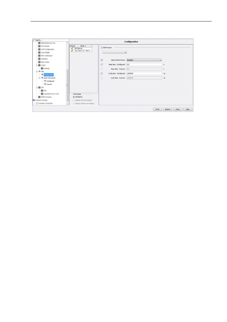
Open the TSN > Configuration dialog.
In the “Cycle time - Configured“ field, enter the cycle time of
1000000 ns.
To save the changes on the device, click the “Write“ button.
Specify the parameters for Device 2.
184
Configuring the network
6.2 Examples for using the MultiCon-
fig™
Figure 41: Enter the Cycle time
The work steps display the values calculated for Device 1 taken from
table 16 on page 182. To configure the parameters for Device 2, use the
values calculated in table 17 on page 183. You assign the mission-critical
data to the priority 5 data stream.
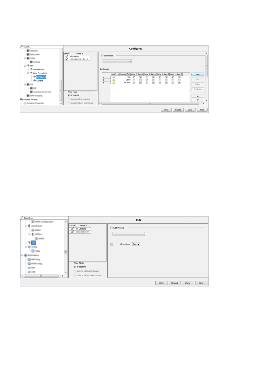
Open the TSN > Gate Control List > Configured dialog.
Select row 1 and click the “Edit“ button.
In the “Interval“ field, enter the value 4100 ns. This is the total gate
open time of Device 1.
Mark the checkboxes for every gate except for “Gate“ 5.
Click the “OK“ button.
To add a new row to the table for the priority 5 TSN data, click the
“New“ button.
In the “Interval“ field, enter the value 3900 ns. This is the minimal gate
open duration of Device 1.
Mark only the checkbox for “Gate“ 5.
Click the “OK“ button.
To allocate the remaining time to the priorities 0, 1, 2, 3, 4, 6,
and 7, click the “New“ button. The remaining time = cycle time - (total
bridge delay + minimal gate open duration).
In the “Interval“ field, enter the value 992000 ns.
Mark the checkboxes for every gate except “Gate“ 5.
Click the “OK“ button.
To save the changes on the device, click the “Write“ button.
To close the “Configured“ dialog, click the “Close“ button.
Specify the parameters for Device 2.
185
Configuring the network
6.2 Examples for using the MultiCon-
fig™
Figure 42: Device 1 TSN > Gate Control List > Configured
After you specified the TSN gate times, enable the PTP and TSN
functions. To enable the functions proceed as follows:
In the folder frame, right-click on the device that you configured as
Device 1. To identify the folder frame, See “Main window of Industrial
HiVision” on page 72.
Select the “MultiConfig™“ option from the drop-down list.
Open the “TSN“ dialog.
In the “Operation“ drop-down list, select the “On“option.
To save the changes on the device, click the “Write“ button.
Specify the parameters for Device 2.
Figure 43: Enable the function
After you have enabled the functions apply the configuration changes. To
apply the changes proceed as follows:
Open the “Devices“ tab.
Double-click the TSN device that you configured as Device 1.
Open the “List“ tab.
186
Configuring the network
6.2 Examples for using the MultiCon-
fig™
Right-click on Port 1.
Select the “MultiConfig™“ option from the drop-down list.
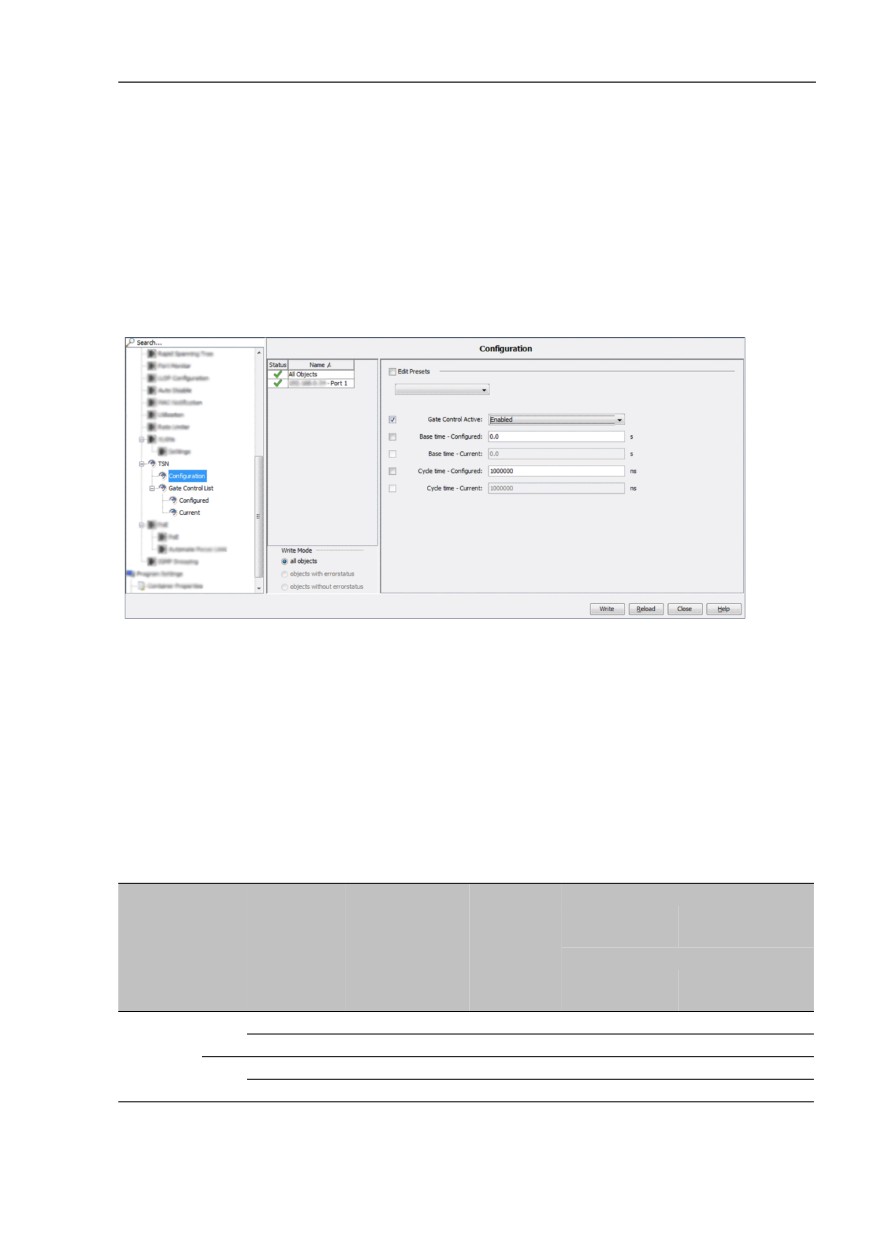
Open the TSN > Configuration dialog.
In the “Gate Control Active“ drop-down list, select the “Enabled“
option.
To save the changes on the device, click the “Write“ button.
Click the “Close“ button.
Figure 44: Enable the port and apply the configuration change
Note: You use the TSN > Gate Control List > Current dialog to display
the setting of the device only. To display the current settings, click the
“Refresh“ button.
Reception delay
Port
RX Medium Independent
Dependent Max. Reception delay [ns]
speed
port
delay [ns]
delay [ns]
68 octets data
1522 octets data
packet
packet
(incl. 4 octets VLAN tag)a
48 octets
1502 octets SDU
SDUb
100 Mbit/s
1/1
Twisted pair
3920 … 3940
80 × SDU
7780
123780
1/2
Optical
3830 … 3840
80 × SDU
7680
123680
1/3
Twisted pair 11480 … 11690 160 × SDU
27050
251370
Optical
11380 … 11600 160 × SDU
26960
251280
187

Configuring the network
6.2 Examples for using the MultiCon-
fig™
Port
RX Medium
Independent Dependent Max. Reception delay [ns]
speed
port
delay [ns]
delay [ns]
68 octets data
1522 octets data
packet
packet
(incl. 4 octets VLAN tag)a
48 octets
1502 octets SDU
SDUb
1 Gbit/s
1/1
Twisted pair
1064 … 1094
8 × SDU
1478
13078
1/2
Optical
924 … 954
8 × SDU
1338
12938
1/3
Twisted pair
3388 … 3538
16 × SDU
4306
27506
Optical
3238 … 3388
16 × SDU
4156
27356
a. These octets are included in the Independent delay, together with PREAMBLE, MAC
addresses and FCS.
b. The VLAN tag is not part of the SDU.
Transmission delay
Port
TX Medium Independent Dependent Max. Transmission delay [ns]
speed
port
delay [ns]
delay [ns]
68 octets data
1522 octets data
packet
packet
(incl. 4 octets VLAN tag)a
48 octets
1502 octets
SDUb
SDU
100 Mbit/s
1/1
Twisted pair
1660 … 1690
0
1690
1690
1/2
Optical
1720 … 1750
0
1750
1750
1/3
Twisted pair
9670 … 9900
8 × SDU
13740
129740
Optical
9730 … 9960
8 × SDU
13800
129800
1 Gbit/s
1/1
Twisted pair
530 … 550
0
550
550
1/2
Optical
510 … 530
0
530
530
1/3
Twisted pair
2904 … 3124
8 × SDU
3508
3892
Optical
2884 … 3104
8 × SDU
3488
3872
a. These octets are included in the Independent delay, together with PREAMBLE, MAC
addresses and FCS.
b. The VLAN tag is not part of the SDU.
188
Configuring the network
6.2 Examples for using the MultiCon-
fig™
6.2.13 Configure polling of device properties
This function lets you easily modify the default settings for polling and status
configuration for a set of device properties. The related MultiConfig™ dialog
is available for every device that supports SNMP and on which you enabled
this protocol. The following categories of properties are monitored through
this dialog:
Device related properties
Redundancy related properties
Reachability related properties
Protocol related properties
Security related properties
Port and interface related properties
To modify the polling and status configuration settings of a property related
to one or more devices, perform the following steps:
In the detail display, open the “Map“ view or another view that displays the
devices.
Select the device or devices on which you want to configure the polling
and status configuration settings.
To open the “MultiConfig™“ dialog, right-click on a selected device and
select “MultiConfig™“.
In the “MultiConfig™“ dialog, select Program Settings > Device
Monitoring in the menu tree.
The “Device Monitoring“ dialog opens.
To enable the polling operation for a property, mark the related “Polling“
checkbox.
To disable the polling operation for a property, unmark the related
“Polling“ checkbox.
To modify the time interval at which Industrial HiVision queries the device,
specify the value in the “Polling Interval“ field. From the related drop-down
list, select the unit of measurement for the time.
To enable Industrial HiVision to determine the status of the property, mark
the “Determine“ checkbox.
To disable Industrial HiVision to determine the status of the property,
unmark the “Determine“ checkbox.
To enable Industrial HiVision to forward the status of the property, mark
the “Forward Status Up“ checkbox.
To disable Industrial HiVision to forward the status of the property,
unmark the “Forward Status Up“ checkbox.
189
Configuring the network
6.2 Examples for using the MultiCon-
fig™
The following steps are available only for the “Temperature“ (“Device“)
property:
To modify the lower temperature threshold, specify the value in the
“Threshold 1“ field.
To modify the upper temperature threshold, specify the value in the
“Threshold 2“ field.
To save the changes, click the “Write“ button.
Note: If minimum one of the selected devices does not support a property,
then the rows related to that property are marked with a blue information icon.
Note: If none of the selected devices support a property, then the polling and
status configuration settings related to that property are not displayed.
Note: If the value of a setting is different for the selected devices, then the
related row is marked with a yellow flag icon. The value related to that setting
is not displayed.
190