Network Management System Industrial HiVision 8.2. User Manual (2021) - page 5
Creating a network plan
5.2 Assigning device icons
Modbus/TCP
Similarly to the System Object Identifier, Modbus/TCP devices contain
information about the manufacturer and the product. Here you can get
Industrial HiVision to assign the icons down to the device level.
MAC Address
The MAC address also contains manufacturer information. Depending on
the manufacturer’s coding depth, you can perform icon assignment from
the manufacturer level down to the device type level.
129
Creating a network plan
5.3 Device arrangement
5.3
Device arrangement
5.3.1
Creating a network plan
For a new network plan, you create a new folder in the folder frame.
Click with the right mouse button on the globe symbol and select New >
Folder in the drop-down list.
Click with the right mouse button on the new folder and select
“Properties...“ in the drop-down list. Give the new folder the name that you
want to use for this network plan.
You can also change the name of a folder by selecting the folder twice or
marking the folder and pressing the F2 key. Complete the entry for the
name by pressing the Enter key.
Right-click on the new folder and select “Scan Ranges“. The “Scan
Ranges“ dialog allows you to define IP address ranges. In this folder,
Industrial HiVision represents newly detected devices with IP addresses
from this IP address range.
130
Creating a network plan
5.3 Device arrangement
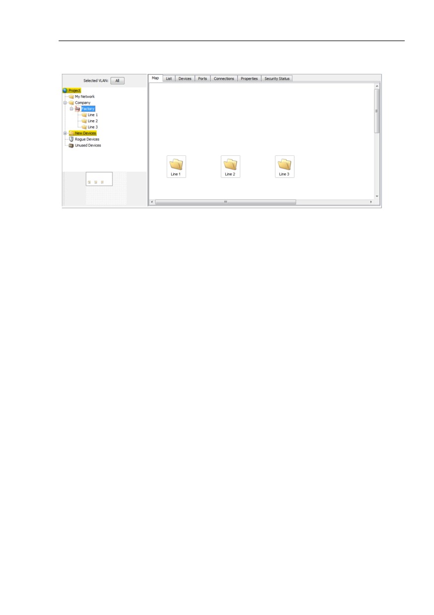
Figure 32: Example of a structure of a network plan
5.3.2
Moving devices into the network plan
Move the newly detected devices into the network plan folder.
Mark these devices.
Click on a device you have marked and move it onto the network plan
folder in the folder frame.
131
Creating a network plan
5.3 Device arrangement
5.3.3
Creating new devices
If you want to enter the network plan before the devices are installed in the
network, you position new devices in the detail display.
Click with the right mouse button in the detail display frame and select
New > Device in the drop-down list.
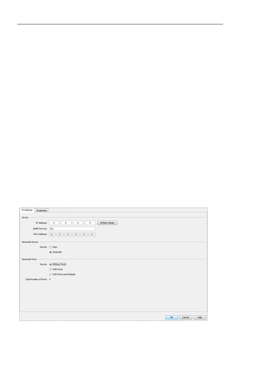
Enter the IP address of the new device in the “IP Address“ tab.
If you have selected the Device > Scan field, when you close the
dialog with “OK“, Industrial HiVision automatically scans the network
for the device.
If you selected Device > Generate, Industrial HiVision adds the option to
create modules and ports for the device to this dialog.
If the new device is separated from the network management station by a
NAT router, for example, then Industrial HiVision can communicate with
the new device using the port forwarding of the NAT router.
You then enter the IP address of the NAT router and the SNMP port
number of the port by means of which Industrial HiVision communicates
with the new device in the “IP Address“ tab. Enter the combination of the
port and the IP address of the new device in the NAT table of the NAT
router.
Figure 33: Entering the IP address of a new device
132
Creating a network plan
5.3 Device arrangement
In the “Properties“ tab you enter
the name you want to give the device and
the status propagation/status determination, if required
(see on page 276 “Properties of a folder/device”).
Select the device and press the F5 key on your keyboard, or right-click on
the device, and select “Refresh“ so that Industrial HiVision detects the
device in the network and calls up its data.
5.3.4
Arrange devices in the detail display
Industrial HiVision supports you in arranging the devices inside the detail
display.
Right-click in the detail frame and select “Auto Layout“, so that Industrial
HiVision repositions the objects in the detailed display, taking your
connections into account.
Right-click in the detail display and select Drawing > Line Up all
Objects to arrange the devices line-by-line.
Select multiple objects in the detail frame, right-click on the detail frame,
and select Drawing > Align Tops/Align Bottoms/Align Left/Align
Right to line up the selected objects in rows/columns.
Here Industrial HiVision selects the outermost object as the position for
the row/column.
Select multiple objects in the detail frame, right-click on the detail frame,
and select Drawing > Center Horizontally/Center Vertically to line
up the selected objects in rows/columns.
Here Industrial HiVision selects the first object selected as the position for
the row/column.
133
Creating a network plan
5.3 Device arrangement
Note: If you have pushed individual objects out of the visible area by moving
object groups, and if they are still contained in the folder frame, you can pull
the objects back into the visible area by right-clicking in the detail window and
selecting “Auto Layout“ or Drawing > Line Up all Objects all objects.
5.3.5
Naming devices and ports
The device/port name that Industrial HiVision displays in the folder frame or
the detail display is taken from the “Properties“ dialog of the device/port by
Industrial HiVision. If no name is entered, Industrial HiVision displays the
management IP address for a device and the module/port number for a port.
To enter the name, right-click on a device/port and select “Properties“.
The configuration settings (see on page 394 “Device/Port Names”) enable
you to automatically transfer
the device/port names from the device and
in the case of the device name, also from the Domain Name Server (DNS)
or from a private hosts file.
5.3.6
Copying devices
In order to represent different monitoring scenarios, for example, Industrial
HiVision gives you the option of copying devices. For this purpose you can
enter different status configurations for copied devices in the “Properties“
dialog. Industrial HiVision has one data record for each device. Every copy
has its own data record. The content of the data record is taken from the
original by the copy.
Example with two monitoring scenarios:
134
Creating a network plan
5.3 Device arrangement
In one monitoring scenario, you want to display only events that you
determine to be critical. A connection break on port 3 of device A would be
critical.
In the other monitoring scenario, you want to display events relevant for
maintenance. The loss of a redundant voltage supply on device A would be
relevant for maintenance.
To realize this, you create two new folders in the folder frame and give one
folder the name “Critical” and the other “Maintenance”.
Right-click on device A and select “Copy“.
Add a copy of device A to each of the “Maintenance” and “Critical” folders.
Double-click on the “Critical” folder to get to the component level.
Double-click on port 3 to go to the detail level.
In the dialog (see on page 283 “Properties of a component detail”),enter
the relevant settings for the“Link“ detail.
Proceed in the same way in the “Maintenance” folder.
5.3.7
Paste as new Network
When you use the “Copy“ and “Paste“ function, Industrial HiVision adds a
duplicate of the original device to the selected folder. The original and
duplicate refer to the same device.
When you use the “Copy“ and “Paste as new Network“ function, Industrial
HiVision copies the device and pastes a new device to the selected folder.
The copied device is another device.
Note: The “Paste as new Network“ function is not available for the following
folders:
“New Devices“
“Rogue Devices“
135
Creating a network plan
5.3 Device arrangement
The “Paste as new Network“ function is useful for identical networks, where
the devices and connections are the same, but the IP addresses are
different.
Along with the connections, the “Paste as new Network“ function also copies
the device parameters. The “Paste as new Network“ function lets you select
which parameters you copy to the devices of the new network. You can verify
the copied parameters in the following dialogs:
“Copy Device Credentials“
The function copies the parameters located in the Preferences > Device
Credentials dialog.
“Copy Event Forwarding“
The function copies the parameters located in the Preferences > Event
Forwarding dialog.
“Copy Event Actions: Alarms“
The function copies the parameters located in the Preferences > Event
Actions > Alarms table.
“Copy Tasks and Schedules“
The function copies the parameters located in the Configuration >
Scheduler dialogs.
The prerequisites for this function are as follows:
Industrial HiVision is in the “Edit Mode“.
Industrial HiVision has discovered the devices you wish to copy.
The devices you wish to copy for the new network are located in the same
folder.
You configure the connections, polling and status configurations on the
original devices.
You only use the original network for other networks with the same
devices and connections.
Example Configuration:
An example for this function, is a train network. When you compare train
networks, they are basically the same. If you make a copy of a train
network, then you change the IP addresses and use the network for
another train.
The prerequisites for the example are as follows:
You have discovered and configured the Train A devices in Industrial
HiVision.
You have the devices that you wish to copy in the same folder.
136
Creating a network plan
5.3 Device arrangement
You have made a Train Networks folder.
The Train A folder is a sub-folder of the Train Networks folder.
In the example that follows you copy the Train A folder, and wish to use
the folder as the Train B network. To use the “Copy“ and “Paste as new
Network“ function proceed as follows:
Make a Train B sub-folder in the Train Networks folder
Open the “Map“ tab of the Train Networks folder.
Right-click on a blank part of the dialog.
Select New > Folder from the drop-down list.
Rename the new folder Train B.
Copy the devices in the Train A folder that you wish to use in the
Train B network.
Open the “Map“ tab of the Train A folder.
Select the devices you wish to copy.
Right-click on a selected device.
Select “Copy“ from the drop-down list.
Paste the devices from the Train A folder to the Train B folder.
Open the “Map“ tab of the Train B folder.
Right-click on a blank part of the dialog.
Select “Paste as new Network“ from the drop-down list.
Give the Train B devices new IP addresses.
Double-click the “Source IP Address“ cell in the first row of the
“Copy Devices“ dialog.
In the Edit > IP Address of the Copy field, enter the first IP
address of the Train B network.
Click the “OK“ button.
The “Copy Devices“ dialog now displays the first IP address of the
Train B network in the “IP Address of the Copy“ column.
To automatically calculate the IP address of the other devices, click
the “Calc with Offset“ button.
Industrial HiVision calculates the offset as follows:
IP Address of the Copy = Source IP Address + IP address
of the first manually set device
To select which parameters you wish to copy to the new devices,
mark the checkboxes at the bottom of the dialog.
137
Creating a network plan
5.3 Device arrangement
To have Industrial HiVision scan the network automatically after
you close the “Copy Devices“ dialog, mark the “Scan Devices after
Copy“ checkbox.
Click the “OK“ button.
Industrial HiVision displays the devices for Train B with the IP
addresses you entered in the “Copy Devices“ dialog.
Note: When you make new IP addresses, verify that you make unique IP
addresses. Industrial HiVision displays duplicate IP addresses with a red
background.
The definition for the icons in the “Type“ column are as follows:
- the IP address is set manually.
- the IP address is calculated.
5.3.8
Devices with multiple IP addresses
Industrial HiVision represents devices with multiple IP addresses, such as a
router, as one device. In the “Properties“ dialog of the device, on the “MAC/
IP Addresses“ tab, you can see which IP addresses are assigned to the
device.
For unique assignment, Industrial HiVision identifies a device with only 1 IP
address. If you want to identify a device with a different IP address, you
delete the device in the interface and create it again with the desired IP
address. After the device is updated, Industrial HiVision identifies the device
with this IP address.
138
Creating a network plan
5.3 Device arrangement
5.3.9
Creating a link
To display a device in a number of network plans, Industrial HiVision gives
you the option of creating links from devices. Connections are particularly
useful if you want to divide your network into several folders. You can then
display in both network plans the device connecting the two network plans
with one another. In contrast to making a copy, the link accesses the data
record of the original. Every change to the original is reflected in the link.
As well as links for devices, you can also create links for components.
Copy the object for which you want to create the link.
Right-click on the position where you want to place the link and select
“Paste as Link“.
139
Creating a network plan
5.4 Device connection
5.4
Device connection
5.4.1
Automatically displaying the topology
The easiest way of displaying links between devices is provided by the “Auto
Topology...“ function of Industrial HiVision.
Select Edit > Auto Topology
In the dialog for automatic topology discovery (see on page 271 “Auto
Topology...”) you select how you want Industrial HiVision to execute the
“Auto Topology...“ function and click “OK“.
Then Industrial HiVision queries the devices for their links. Industrial HiVision
displays the detected links in the interface and starts monitoring the link state
and load.
In the case of Wireless Local Area Networks (WLAN), Industrial HiVision
displays wireless connections with dashed lines. Because access stations
can be mobile, roaming from one access point to another is a completely
normal process. Therefore, Industrial HiVision does not include the
connection status in the status configuration of radio connections.
Industrial HiVision detects a break in the connection to the access point after
the polling time for determining the status of the access point has elapsed.
140
Creating a network plan
5.4 Device connection
5.4.2
Connecting devices manually
After you have arranged the devices to meet your requirements, you add the
connections between the devices.
Click on the center of a device symbol. Click again and, holding down the
mouse button, move the cursor onto the device symbol with which you
want to connect the device.
5.4.3
Reshaping a connection line
Industrial HiVision allows you to reshape connection lines. Thus, for
example, you can represent a HIPER-Ring just like a ring.
Select the connection in order to bend the line or give it a curved shape.
Depending on the shape of the connection and the selection, the following
options are available to you (see bubble help):
Add an anchor point with one click on the handle.
Switch between “Add anchor point” and “Change shape of curve” by
re-selecting the connection.
Delete the anchor point by double-clicking.
Change the shape of the curve using the handle.
Straighten the connection piece with one click on the handle.
141
Creating a network plan
5.4 Device connection
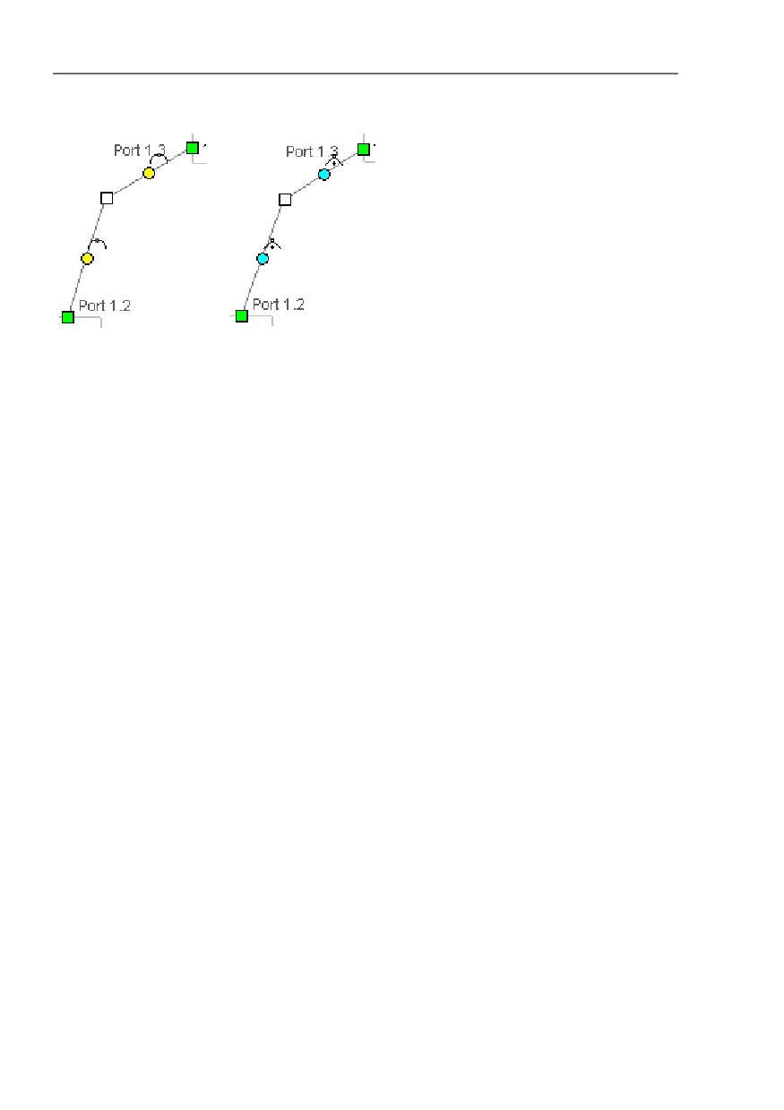
Figure 34: Reshaping a connection
- left: change shape of curve
- right: add anchor point
5.4.4
Specifying the line thickness
Depending on the selected background image, the connection lines can
blend into the background. Industrial HiVision gives you the option of
changing the line thickness. This enables you to make the lines more distinct
from the background.
You set the line thickness globally in the menu Preferences > Display >
Device (see on page 362 “Appearance”).
142
Creating a network plan
5.4 Device connection
5.4.5
Other connections
In the same way as you can connect devices, Industrial HiVision also gives
you the option of connecting folders and components other than symbols and
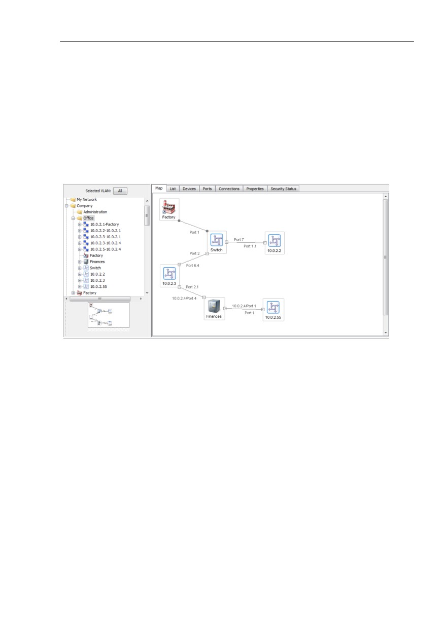
text with one another. In the illustration below, (see figure 35) you will find an
example of a connection with a folder.
Figure 35: Connection with a folder
5.4.6
Detecting a link to another folder
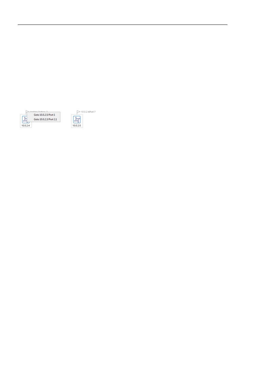
Industrial HiVision uses a flag to indicate links to a device or folder outside
the current folder. Beside the flag you will find information about where the
link leads to. If the link has multiple destinations, Industrial HiVision groups
the destinations together and the bubble help shows you the destinations.
143
Creating a network plan
5.4 Device connection
When you double-click on the flag,
you go directly to the port named in the destination if a single device is
connected, or
you open a drop-down list if the flag points to multiple destinations. The
drop-down list shows the destination of the link. Select the link whose
ports you want to go to.
Figure 36: Flags as link indicators
5.4.7
Specifying connection properties
Specify the connection properties.
Right-click on a connection line and select “Properties...“ (see on
page 290 “Properties of a connection”).
On the “Connection“ tab you enter the ports to which the line is connected.
Click your way through the tree structure until you can select the port on
the device to which you are connecting the line.
Also on the “Connection“ tab, select the properties you want to monitor
under “Monitor“. In the default setting, Industrial HiVision automatically
monitors the connection interruption, network load and port redundancy.
144
Creating a network plan
5.4 Device connection
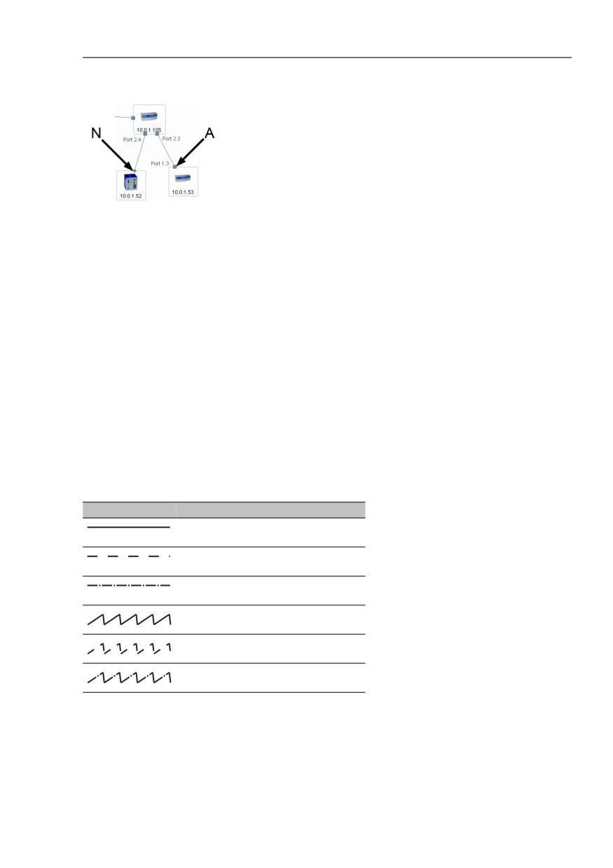
Figure 37: Monitoring state of a connection
N - No link monitoring
A - Active link monitoring
5.4.8
Link types
For clarification purposes, Industrial HiVision represents the links in different
ways, according to their character.
Representation Meaning
Normal link
Stand-by link
Interrupted link
Radio link
Stand-by radio link
Interrupted radio link
Table 10: Link types
145
Creating a network plan
5.4 Device connection
5.4.9
Representation of the connection medium
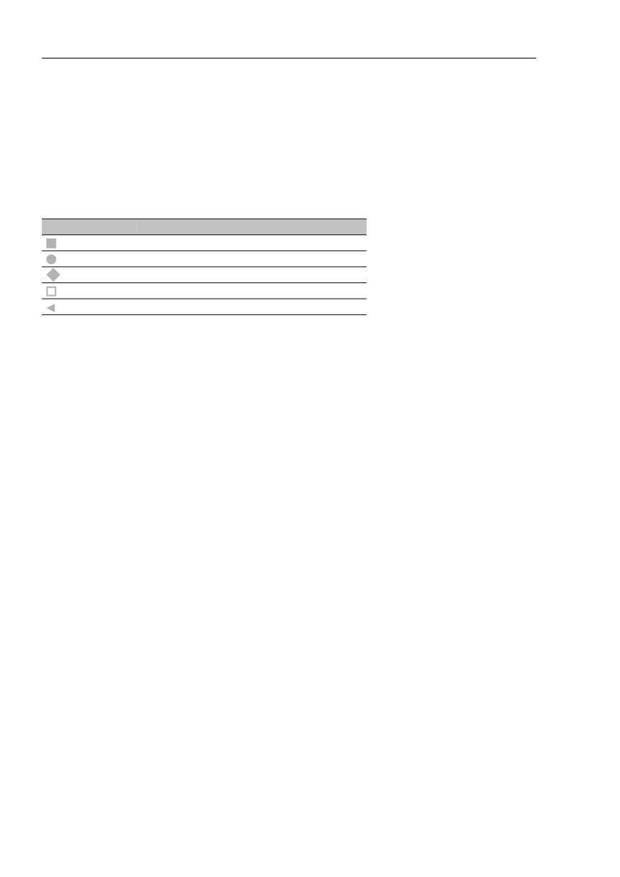
Industrial HiVision enables you to identify the medium of a connection based
on the icon for the connection ends (see on page 291 “Connection”).
Representation Meaning
Copper
Optical
Wireless, sawtooth line
Unmanaged
Unknown
Table 11: Representation of the connection medium
146
Creating a network plan
5.5 The Network changing over time
5.5
The Network changing over
time
Rarely does your network remain in a static condition. Generally, from time
to time new devices are added and other devices removed and then
reinserted in other positions.
5.5.1
Adding devices with HiDiscovery V1
A simple method of adding a new device is to use the HiDiscovery V1 button
in the tool bar.
Click on the HiDiscovery V1 button in the tool bar.
Industrial HiVision starts a network request.
Industrial HiVision displays newly detected Hirschmann devices that do
not have an IP address yet in the “New Devices“ folder.
Industrial HiVision displays newly detected Hirschmann devices that
already have an IP address in the default map for the address range (see
on page 322 “[Basics]”).
As described on the previous pages, you can move the new devices among
your network folders and create links.
147
Creating a network plan
5.5 The Network changing over time
Assigning the IP address
After you have added a new device for example, with HiDiscovery V1,
Industrial HiVision gives you an option of assigning an IP address to the
device (see on page 414 “IP Configuration”).
Right-click on the device and select “IP Configuration“. With the “IP
Configuration“ dialog you can enter the following parameters
- the device name
- the IP address
- the network mask
- the gateway IP address
5.5.2
Adding devices with network scan
A method of adding a new device with a previously configured IP address is
provided by the “Scan Network“ button in the tool bar.
Click on the “Scan Network“ button in the tool bar.
Industrial HiVision starts a network inquiry in accordance with the settings
under “[Basics]” on page 322. Industrial HiVision displays newly detected
devices in the default map for the address range (see on page 322
“[Basics]”).
As described on the previous pages, you can move the new devices among
your network folders and create links.
5.5.3
Adding devices manually
Another option for adding a new device is to add the device manually (see on
page 132 “Creating new devices”).
148
Creating a network plan
5.5 The Network changing over time
As described on the previous pages, you can move the new devices among
your network folders and create links.
5.5.4
Startup procedure for Hirschmann devices
Industrial HiVision simplifies the startup procedure for Hirschmann devices.
Apart from the installation, you can start up Hirschmann devices from your
network management station:
Detect Hirschmann devices using HiDiscovery V1 (see on page 122
“Device detection”).
Configure the IP parameters (see on page 414 “IP Configuration”).
Enter the trap destination address (see on page 416 “Trap Destination”).
For a new device, you use the Web interface to change the SNMP
password.
Enter the new SNMP password in Industrial HiVision (see on page 376
“Device Credentials”).
5.5.5
Interrupting device monitoring
To reduce the load on your network, Industrial HiVision provides you with the
following options for interrupting the monitoring for individual devices and
folders:
Move the device into the “Unused Devices“ folder.
Right-click on the device and select “Unmanage“ in the drop-down list.
Industrial HiVision displays the device in gray.
149
Creating a network plan
5.5 The Network changing over time
5.5.6
Removing devices
To remove a device proceed as follows:
Right-click on the device and select “Delete“ in the drop-down list (see on
page 94 “Folder frame”).
Industrial HiVision allows you to delete the device or move it into the
“Unused Devices“ folder.
5.5.7
Exchanging devices
In order to meet the time requirements, by degrees you will have to replace
existing devices in your data network with newer devices that have new
functions.
Industrial HiVision provides a conversion tool for this scenario, with which
you can save the configuration of a Classic device as an XML file in a file
path.
A list of the devices that support this feature can be found on the FAQ page
of Hirschmann:
configuration-of-a-powermice-to-msp
Highlight the Classic device that you want to replace with a HiOS device.
Select Configuration > MultiConfig™.
In the MultiConfig™ dialog select:
Device Settings > Advanced > Configuration Saver
Check the file path, file name and click on “Write“
Industrial HiVision saves the configuration in an XML-format file.
In the next step, migrate the saved Classic devices configuration to the HiOS
device, which you previously installed and created in the network plan.
Highlight the HiOS device, onto which you want to apply the configuration
of the Classic device.
Select Configuration > MultiConfig™.
In the MultiConfig™ dialog select:
Device Settings > Advanced > Configuration Migrator
150
Creating a network plan
5.5 The Network changing over time
Select the previously saved XML file using the file selection dialog.
Check the file path and file names for the log file, in which Industrial
HiVision will log the result of the migration and then click “Write“.
Industrial HiVision transfers the migrated configuration from the Classic
device onto the HiOS device.
If the “Status“ column in the dialog shows that the HiOS device has
rejected the configuration data, you will find information on possible
causes in the log file.
You will find the path to the log file under Configuration >
Preferences > Advanced > Load/Save > Configuration Saver.
151
Creating a network plan
5.6 Network Documentation
5.6
Network Documentation
Industrial HiVision provides a number of functions to assist you in the
documentation of your network.
5.6.1
Saving Industrial HiVision projects
Industrial HiVision allows you to save your current network data and the
configuration of Industrial HiVision in a project file (see “Save” on page 257
and “Save as...” on page 258).
5.6.2
Saving reporting data
Industrial HiVision records the data of the reporting function (see on
page 307 “Reporting”) in a separate database outside of the project. You will
find this database in the installation directory in the subdirectory report_db.
As this subdirectory may contain reporting databases from multiple projects,
Industrial HiVision creates a subdirectory for each project therein:
<INSTALL_DIR>/report_db/<UUID>/pm.h2.db
You will find the UUID in the help menu in the kernel info.
152
Creating a network plan
5.6 Network Documentation
5.6.3
Exporting the content of the detail display
Industrial HiVision allows you to export the content of the detail display (see
on page 260 “Export...”).
Choose File > Export... and select the file type in the “Save“ window.
5.6.4
Printing the content of the detail display
Industrial HiVision allows you to print the content of the detail display.
Select File > Print.
Industrial HiVision creates a temporary PDF file of the content of the detail
display and opens this PDF file in the PDF display program for example,
Acrobat Reader, that is installed on your management station.
5.6.5
Exporting the event list
Industrial HiVision allows you to export the complete event list (see on
page 260 “Export Events...”).
Choose File > Export Events... and select the file type in the “Save“
window.
153
Creating a network plan
5.6 Network Documentation
5.6.6
Printing the event list
Industrial HiVision allows you to print the complete event list.
Select File > Print Events.
Industrial HiVision creates a temporary PDF file of the content of the detail
display and opens this PDF file in the PDF display program for example,
Acrobat Reader, that is installed on your management station.
5.6.7
Creating device documentation
Industrial HiVision allows you to create device documentation. In the device
documentation, Industrial HiVision creates a PDF file for every device
selected. The PDF file contains information about the device and its settings.
In the detail window, mark the devices you want to document.
In the menu bar, select Edit > Device Documentation > Document
Selected Devices or right-click a selected device and choose “Document
Selected Devices“.
In the “Choose a directory for placing device documentation files“ window,
enter the folder in which you want Industrial HiVision to write the PDF files
and click “Select“.
For each device selected, Industrial HiVision writes a PDF file with the name:
“inventory_<IP address>.pdf” in this folder.
154
Creating a network plan
5.6.8
Printing or exporting the status
configuration
Industrial HiVision allows you to print or export the status configuration (see
on page 403 “Status Configuration”).
Select Configuration > Status Configuration.
Click “Print“.
Industrial HiVision creates a temporary PDF file of the status configuration
and opens this PDF file in the PDF display program for example, Acrobat
Reader, that is installed on your management station.
Click “Export“.
Industrial HiVision allows you to export the list in the following forms:
a PDF file
an HTML file
a CSV file (see on page 457 “CSV export”)
5.6.9
Agent
The “Agent“ folder is found in the expanded device tree in the folder frame.
The “Agent“ folder contains the following information about the PSM device
discovered by Industrial HiVision:
“GVRP“ - displays the status of the GVRP protocol
“VLANs“ - displays the configured VLANs
“LLDP Chassis ID“ - displays the chassis ID
“LLDP System Name“ - displays the device name
“Number of Users“ - displays the number of connected devices on the port
“Base MAC Address“ - displays the MAC address of the device
“Firmware Version“ - displays the running firmware version
155
Creating a network plan
“Other Firmware Info“ contains the following information about the PSM
device:
“Backup Firmware“- displays the stored backup firmware
“Stored Firmware“ - displays the current stored firmware
“Boot Code Firmware“ - displays the stored boot code firmware
“Interface“ contains the following information about the PSM device:
“Netmask“ - displays the configured Netmask
“Default Gateway“ - displays the configured Default Gateway
“MAC Address“ - displays the MAC address of the device
“IP Address“ - displays the IP Address of the device
“IP Address Conflict“ - displays the status if an IP Address Conflict occurs
156
Configuring the network
5.6 Network Documentation
6
Configuring the network
When you have your network displayed in Industrial HiVision, with your
devices and connections, you can configure the devices.
The multi-configuration function (MultiConfig™) allows you to perform
configurations on the device and in Industrial HiVision for:
one or more devices
one or more device properties, also device overlapping
one or more device details, also device overlapping
You go to the MultiConfig™ dialog by selecting at least one device or
property in the detail display and choosing Configuration > MultiConfig™
in the menu bar.
Note: Keep in mind how this affects your system resources (see on page 222
“Effect on system resources”).
157
Configuring the network
5.6 Network Documentation
When you select objects for example, devices, ports, or connections, to
configure with MultiConfig™, Hirschmann recommends that you only select
objects with the following matching characteristics:
“Device Class“
“Product“
“Chassis“
“Firmware Version“
The reason for matching the characteristics, is that MultiConfig™ only
displays the common supported dialogs. Displaying only common dialogs
leads to a smaller number of dialogs. A smaller number of dialogs leads to
fewer number of functions available for the selected objects.
Note: With different software versions on the devices, MultiConfig™ can
display dialogs which are available for the selected objects. In this case, you
can configure the functions in the dialogs. When you configure functions on
devices with different software, warning and error messages can result
depending on the object you are configuring.
158
Configuring the network
6.1 Using the dialog box
6.1
Using the dialog box
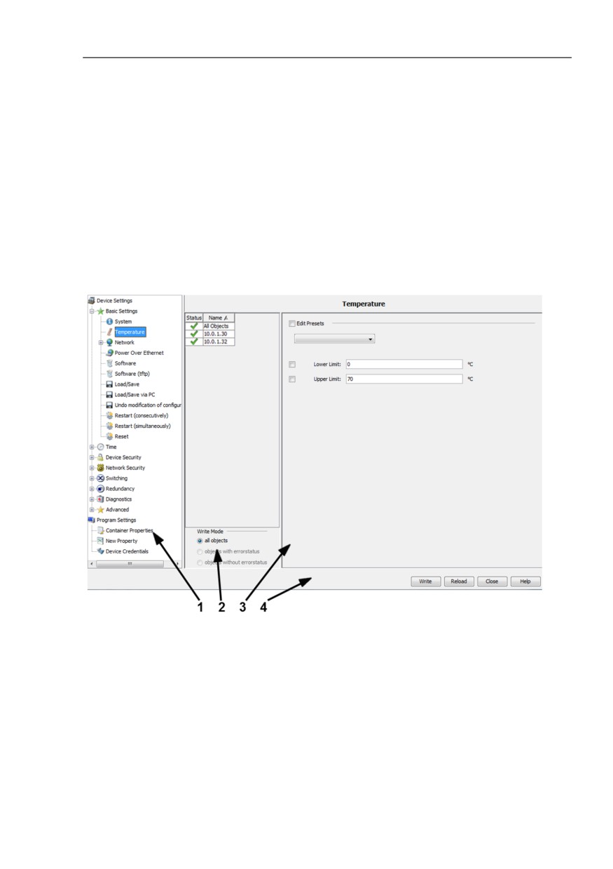
The MultiConfig™ dialog contains 3 frames:
Web-based, interface-type menu tree
Object frame
Function frame
Figure 38: MultiConfig™ dialog overview
1 - Menu tree
2 - Object frame
3 - Function frame
4 - Control elements
159