Network Management System Industrial HiVision 8.2. User Manual (2021) - page 3
Preparation
3.6 Fingerprint verification
3.6
Fingerprint verification
As described in “Physical protection” on page 43, secure the physical access
to the kernel host against unauthorized access. The remote GUI client also
requires protection against connecting to a fraudulent kernel host. To verify
that the remote GUI client is connecting to the correct kernel host server, use
the fingerprint verification function.
During the initial installation, Industrial HiVision creates a certificate and
saves it in the key store. Industrial HiVision generates an SHA-256 fingerprint
from the certificate. The fingerprint used for verification is unique for every
Industrial HiVision application.
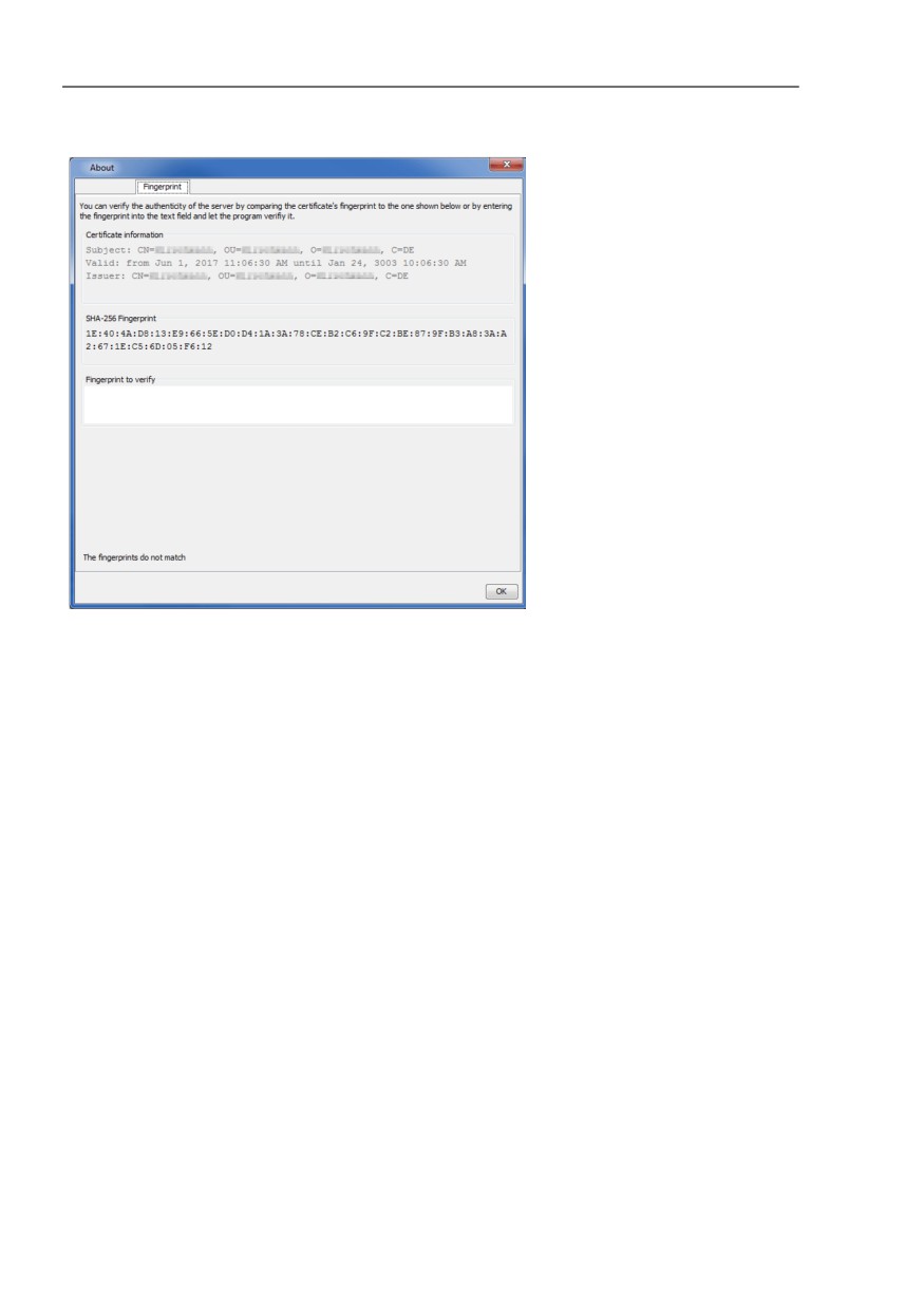
You can find the fingerprint in the Help > About > Fingerprint > SHA-256
Fingerprint text field. The “Fingerprint“ dialog also displays additional
certificate information. For example, who created the certificate, the creation
date, and the expiration date.
Note: The management stations located in the subdomains accept the
fingerprint of the kernel host without notification.
To verify that the remote GUI client is connecting to the correct kernel host,
proceed as follows:
The remote user requests the fingerprint of the kernel host server from the
administrator. To find and send the fingerprint, the administrator proceeds
as follows:
- Open the Help > About > Fingerprint tab.
- Copy the fingerprint from the “SHA-256 Fingerprint“ field.
- Pastes the fingerprint into a text file.
- Using a secure communications channel, send the text file to the
remote user.
65
Preparation
3.6 Fingerprint verification
Figure 5: Help > About > Fingerprint tab
To connect the remote GUI client to the kernel host server, proceed as
follows:
- Click the “File“ option on the toolbar.
- Select the “Login“ option from the drop-down list.
- In the “Enter Server“ dialog, enter the IP address of the server
containing the kernel host.
- Click the “OK“ button.
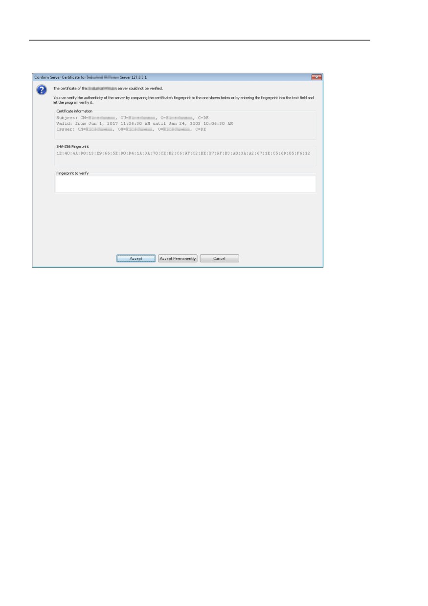
Industrial HiVision opens the “Confirm Server Certificate for Industrial
HiVision Server“ dialog.
66
Preparation
3.6 Fingerprint verification
Note: If the kernel host and remote GUI client are both located in the same
private network, then leave the text field empty. Click either the “Accept“ or
“Accept Permanently“ button.
Enter the fingerprint received from the administrator in the “Fingerprint to
verify“ text field.
- If the fingerprint is a mismatch, then the text field displays red
characters. The dialog also displays the message, “The fingerprints do
not match“. Click the “Cancel“ button and contact your administrator.
- If the fingerprints match, then the “Accept“ and “Accept Permanently“
buttons are active. The dialog also displays the message, “The
fingerprint matches this server's fingerprint“.
- When you click the “Accept“ button, the remote GUI client connects to
the kernel host. If the connection to the server terminates, then
Industrial HiVision requires that you reverify the fingerprint in order to
re-establish the connection.
- When you click the “Accept Permanently“ button, Industrial HiVision
saves the fingerprint with the associated IP address. If the connection
terminates, then Industrial HiVision re-establishes the connection
without fingerprint verification.
Note: Whenever the fingerprint is accepted, Industrial HiVision makes an
entry in the log file.
67
Preparation
3.6 Fingerprint verification
Figure 6:
“Confirm Server Certificate for Industrial HiVision Server“ dialog
Industrial HiVision allows you to connect the remote GUI client to different
kernel host servers. If the fingerprint for a previously trusted server has
changed or is no longer trustworthy, then “distrust” the certificate.
Industrial HiVision allows you to distrust a certificate on the kernel host or on
the remote GUI client.
When you delete the “corbas.jks” file on the kernel host server, after a
restart Industrial HiVision creates a new “corbas.jks” file containing a new
certificate. Every remote GUI client is required to accept the fingerprint of
the new certificate.
When you delete the “corbas.jks” file on the remote GUI client, you delete
the fingerprints of every trusted server. After you restart Industrial
HiVision, Industrial HiVision creates a new “corbas.jks” file. To rebuild the
“corbas.jks” file, accept the fingerprints of the trusted servers again.
To distrust a server either on the kernel host or the remote GUI client,
proceed as follows:
Verify that you have administrator rights.
Navigate to the "config" folder in the installation directory.
Delete the “corbas.jks” key store file
Restart the Industrial HiVision application.
68
Preparation
3.6 Fingerprint verification
To rebuild the “corbas.jks” key store file on the remote GUI client, perform the
following work steps for every required kernel host server:
Reconnect to a kernel host server.
Verify that the fingerprint displayed in the dialog matches the fingerprint
received from the administrator.
69
Interface of the program
4
Interface of the program
This chapter describes the structure of the program interface. It provides you
with an overview to help you find your way in the graphic interface. You will
find a detailed description in the chapter “References” on page 253.
Expert knowledge of networks is not required to use Industrial HiVision. The
interface enables you to operate the program intuitively. It contains elements
of standard user interfaces, so you will be able to get started after a brief
familiarization phase.
71
Interface of the program
4.1 Main window of Industrial HiVision
4.1
Main window of Industrial
HiVision
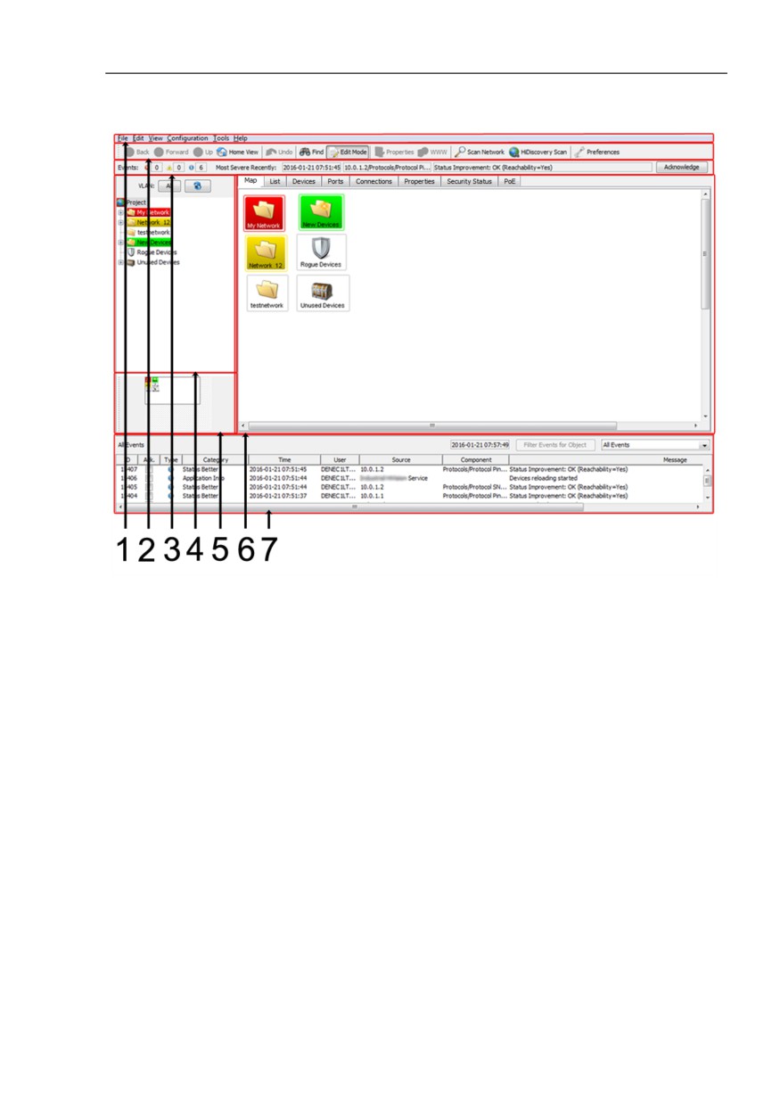
When you start Industrial HiVision, the main window appears on the screen.
It consists of the following parts:
Menu bar
Tool bar
Event line
Folder frame
Navigation field
Detail display
Event list
By positioning the mouse on a screen position in Industrial HiVision for a
short time, you open an information window with a small help text.
In the event list area, Industrial HiVision shows the time that is synchronized
with the system time of the computer. Industrial HiVision updates this time
every second.
If the time displayed matches the system time of the computer, you can
assume that the displayed content of Industrial HiVision is up to date.
72
Interface of the program
4.1 Main window of Industrial HiVision
Figure 7: Main window
1 - Menu bar
2 - Tool bar
3 - Event line
4 - Folder frame
5 - Navigation field
6 - Detail display
7 - Event list
73
Interface of the program
4.2 Menu bar
4.2
Menu bar
The menu bar is right at the top of the main window of the program. It gives
you support in importing, exporting, and creating new projects, in copying,
adding, and deleting data, and in changing the view and configuration. A help
menu is also provided. See “Main window of Industrial HiVision” on page 72.
The menu bar contains the following selection items:
“File“
“Edit“
“View“
“Configuration“
“Tools“
“Help“
Note: When you start Industrial HiVision from HiView some options are
missing from the selection items.
74
Interface of the program
4.2 Menu bar
4.2.1
File
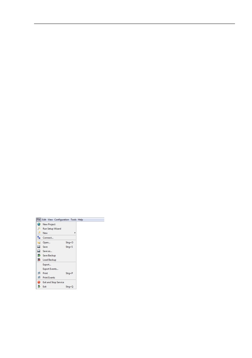
The “File“ menu item in the menu bar contains the following selection fields:
“New Project“
“Run Setup Wizard“
“New“
“Login“
“Logout“
“Open...“ (Ctrl+O)
“Save“ (Ctrl+S)
“Save as...“
“Save Backup“
“Load Backup“
“Export...“
“Export Events...“
“Print“ (Ctrl+P)
“Print Events“
“Exit and Stop Service“
“Exit“ (Ctrl+Q)
The key combinations in brackets allow you to start the selection items
without using the mouse.
Figure 8: Menu bar - file
75
Interface of the program
4.2 Menu bar
4.2.2
Edit
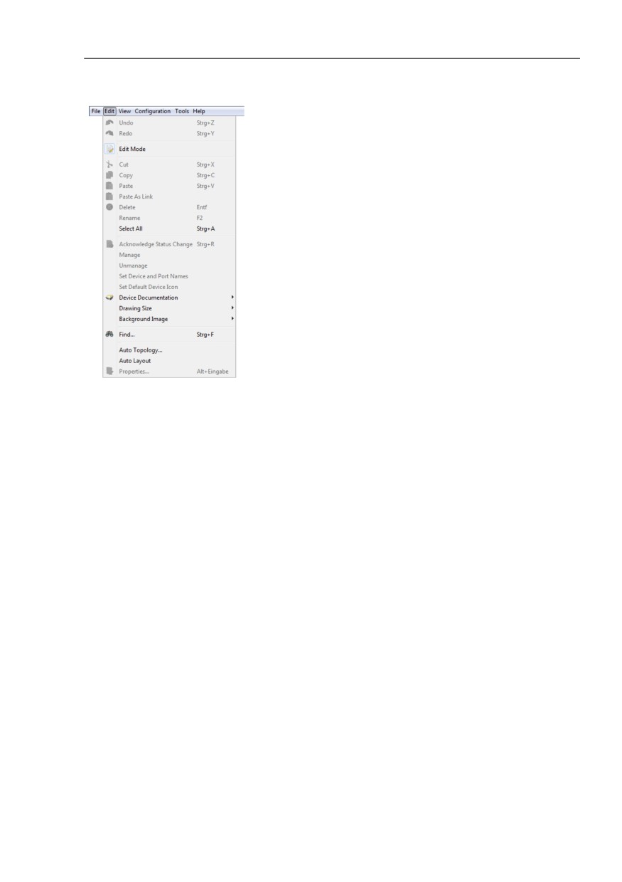
The “Edit“ menu item in the menu bar contains the following selection fields:
“Undo“ (Ctrl+Z)
“Redo“ (Ctrl+Y)
“Edit Mode“
Switch to the Free Version (available during the 30-day trial period)
“Cut“ (Ctrl+X)
“Copy“ (Ctrl+C)
“Paste“ (Ctrl+V)
“Paste as Link“
“Delete“ (Del)
“Rename“ (F2)
“Select All“ (Ctrl+A)
“Acknowledge Status Change“
“Manage“
“Unmanage“
“Set Device and Port Names“
“Set Default Device Icon“
“Device Documentation“
“Drawing Size“
“Background Image“
“Find...“ (Ctrl+F)
“Auto Topology...“
“Auto Layout“
“Properties...“ (Alt+Enter)
The key combinations in brackets allow you to start the selection items
without using the mouse.
76
Interface of the program
4.2 Menu bar
Figure 9: Menu bar - edit
4.2.3
View
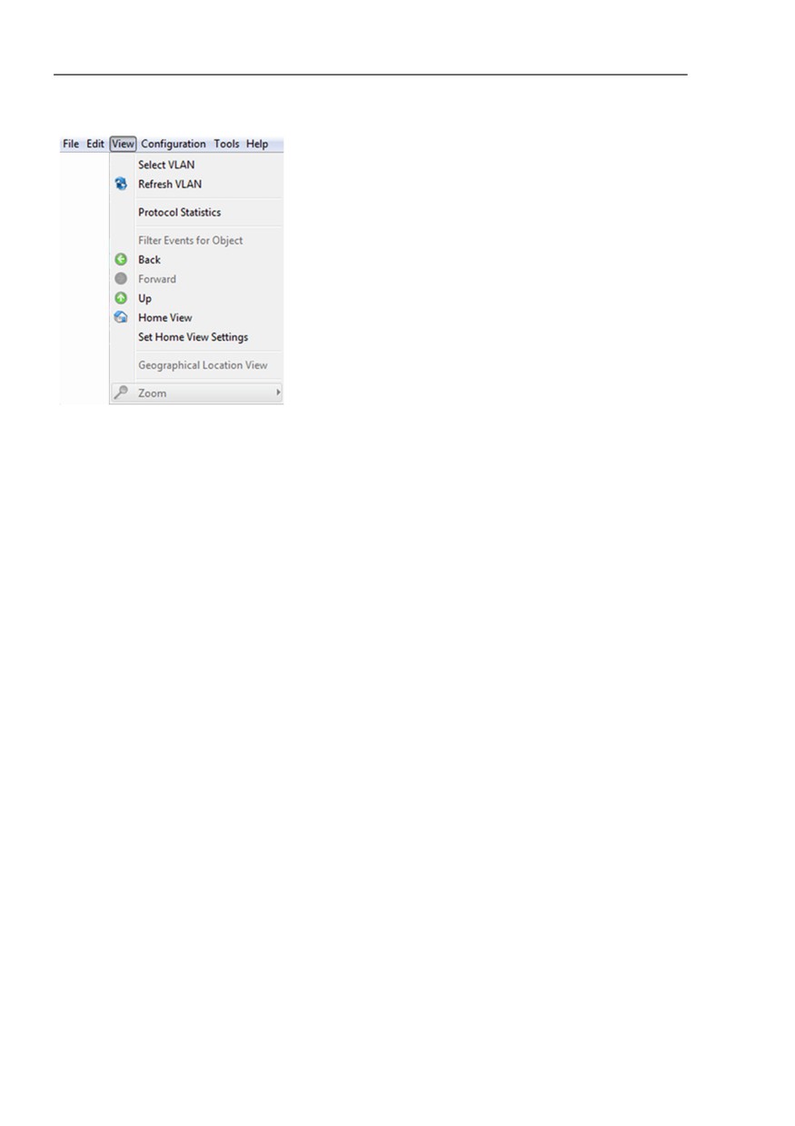
The “View“ menu item in the menu bar contains the following selection fields:
“Select VLAN“
“Refresh VLANs“
“Protocol Statistics“
“Filter Events for Object“
“Back“
“Forward“
“Up“
“Home View“
“Set Home View Settings“
“Geographical Location View“
“Zoom“
77
Interface of the program
4.2 Menu bar
Figure 10: menu - View
4.2.4
Configuration
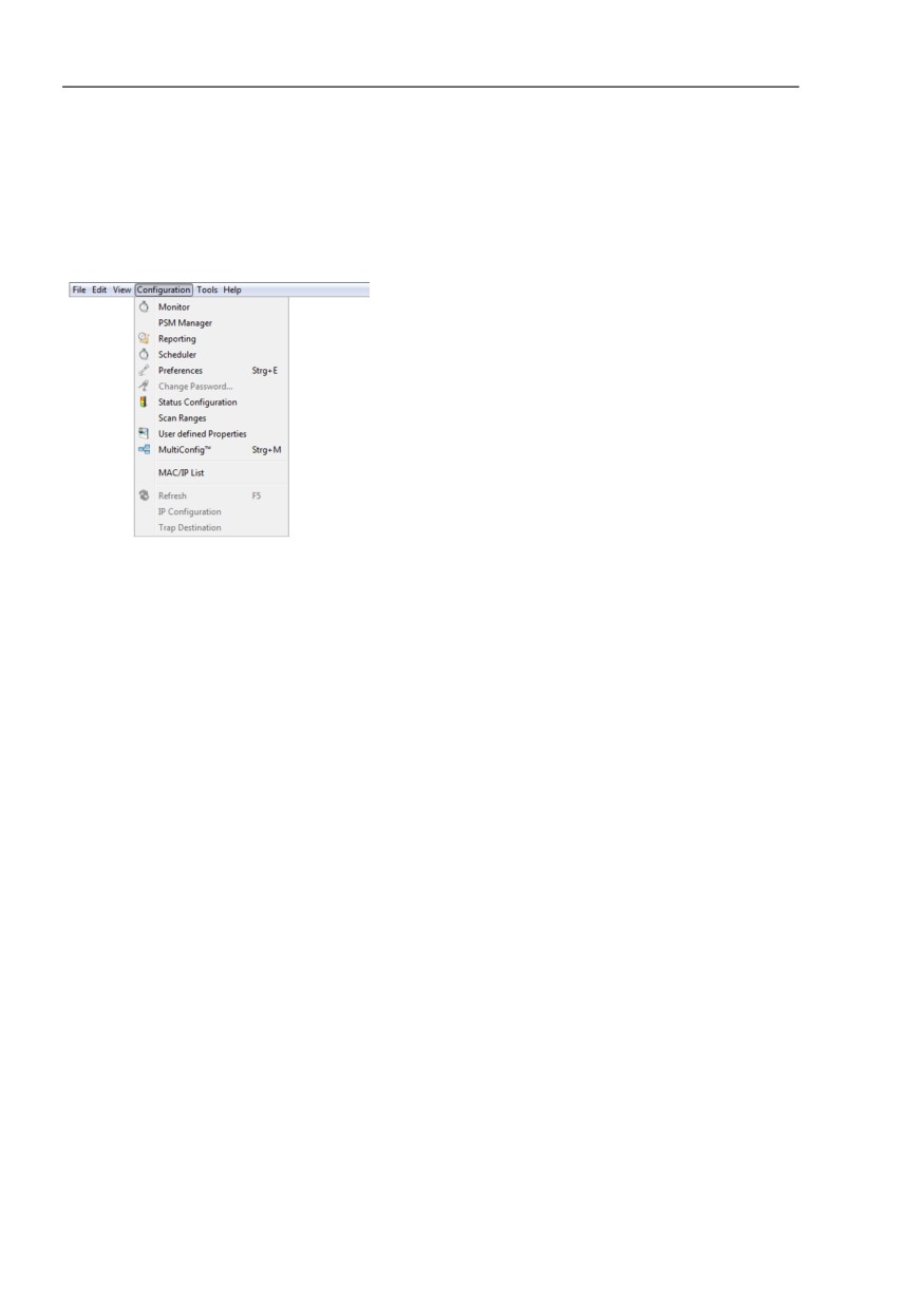
The “Configuration“ menu item in the menu bar contains the following
selection fields:
“Monitor“
This dialog gives you an overview of the setting of the monitored
components. (see on page 304 “Monitor”).
“PSM Manager“
Product-Specific Modules (PSMs) describe the properties of a device
which Industrial HiVision can read for monitoring or write to for
configuration.
The PSM Manager gives you the opportunity to update PSMs or import
additional PSMs beyond the ones included with delivery and remove them
again.
See “PSM Manager” on page 306.
“Reporting“
The reporting function allows you to manage long-term statistics outside
the database of the network management system program.
See “Reports” on page 216.
78
Interface of the program
4.2 Menu bar
“Scheduler“
Scheduler offers the possibility of having repeating tasks of Industrial
HiVision carried out automatically.
See “Scheduling” on page 308.
“Preferences“ (Ctrl+E)
You use this selection field to enter settings for the configuration of
Industrial HiVision(see on page 319 “Preferences”).
“Change Password...“
“Status Configuration“
With this dialog you can perform the status configuration of component
details for the devices in a device class, or for all devices.
“Scan Ranges“
With this dialog you can enter the scan ranges for the device discovery.
“User defined Properties“:
With the “User defined Properties“ function, Industrial HiVision allows you
to include additional properties from the MIB of SNMP-capable devices in
the management (see on page 219 “User-defined properties”).
MultiConfig™
The multi-configuration function (MultiConfig™) allows you to perform
configurations on the device and in Industrial HiVision for:
- one or more devices
- one or more device properties, also for all the devices
- one or more device details, also for all the devices
“MAC/IP List“
MAC/IP list of the discovered devices.
“Refresh“ (F5)
The “Refresh“ option allows you to update the properties or refresh
selected devices.
“IP Configuration“
This dialog enables you to configure the IP parameters of a device
detected by HiDiscovery V1 without an IP address, or to change IP
parameters already configured.
“Trap Destination“
When the dialog is opened, Industrial HiVision queries the trap settings of
the device and displays whether the device sends traps to the IP address
displayed.
79
Interface of the program
4.2 Menu bar
The key combinations in brackets allow you to start the selection items
without using the mouse.
Figure 11: Menu bar - configuration
80
Interface of the program
4.2 Menu bar
4.2.5
Tools
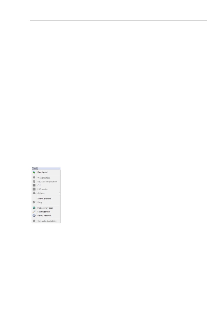
The “Tools“ menu item in the menu bar contains the following selection fields:
“Dashboard“
“Web Interface“
“Device Configuration“
“CLI“
“Actions“
“SNMP Browser“
“Ping“
“HiDiscovery Scan“
“Scan Network“
“Demo Network“
“Calculate Availability“
You can activate menu items displayed in gray by selecting a device or
property that supports this function.
Figure 12: Menu bar - tools
81
Interface of the program
4.2 Menu bar
4.2.6
Help
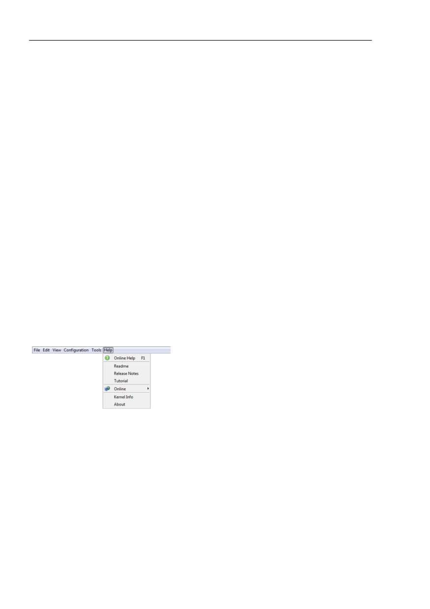
The “Help“ menu item in the menu bar contains the following selection fields:
“Online Help“, (F1)
“Readme“
“Release Notes“
“Tutorial“
“Online“
“Kernel Info“
“About“
You can use the F1 key to start the online help without using the mouse.
Online Help (F1)
You select his field to start the online help of the program.
About
You select this field to open a window with information on the program.
Figure 13: Menu bar - Help
82
Interface of the program
4.3 Tool bar
4.3
Tool bar
In the tool bar you can quickly access frequently used functions by clicking
on the relevant button. See “Main window of Industrial HiVision” on page 72.
The tool bar contains the following selection fields:
“Back“
“Forward“
“Up“
“Home View“
“Undo“
“Find“
“Edit Mode“
“Properties“
“WWW“
“Scan Network“
“HiDiscovery Scan“
“Preferences“
Grayed-out selection fields cannot be used at the present time. This is the
case, for example, if you want to use “Up“ to reach a higher level when you
are already on the highest level.
83
Interface of the program
4.3 Tool bar
4.3.1
Edit Mode
Industrial HiVision provides two operating modes. You use the “Edit Mode“
button to switch between these two operating modes. You can password
protect the “Edit Mode“ button. You can use either the “Edit Mode“ password
or the password from active administrators to password protect the “Edit
Mode“ button.
Another way to restrict the “Edit Mode“ access, is to use the time of expiry.
Here you can specify how long the edit mode is allowed to be active (see on
page 369 “Program Access”).
“Edit Mode“
The “Edit Mode“ is the administrative mode. Verify that you have specified
at least 1 user with administrator access. To specify a user as an
administrator, mark the “Login“, “Edit Mode“, “User Management“, and
“Web Access“ checkboxes in the “User Management“ dialog. See “User
Management” on page 327.
The following list contains some of the parameters that you can configure
in the “Edit Mode“:
- network display in the graphic user interface
- monitoring parameters
- configure security parameters
- copy a network for reuse, See “Paste as new Network” on page 135.
- user management and authorization roles, See “User Management”
on page 327.
- signaling device ports, See “Device and Port Signaling” on page 295.
- configure the Home View parameters, See “Set Home View Settings”
on page 302.
- scheduling tasks, See “Scheduler” on page 312.
- automatic device log on, See “Web Interface” on page 435.
84
Interface of the program
4.3 Tool bar
- configure the “Dashboard“ function, See “Dashboard” on page 418.
- functions listed in the run mode section
Run Mode
The run mode is used only to monitor the network. When you specify a
role that only has the “Login“ authorization, the user can only operate
Industrial HiVision in the run mode. See “User Management” on
page 327.
The following list contains some of the functions that you can monitor in
the run mode:
- open the various tabs to view the network statuses
- start the “Dashboard“ to monitor the network, See “Dashboard” on
page 418.
- use the “Find“ button to look for devices, See “Find...” on page 270.
- use the “Home View“ button to revert back to the home settings,
See “Home View” on page 301.
- use the “Forward“, “Back“ and “Up“ navigation buttons
- log out of Industrial HiVision
Note: The run mode is used to avoid unintentionally writing to the Industrial
HiVision parameters. The run mode is also used to avoid a database access
conflict. For example, the “Edit Mode“ allows only 1 user at a time to edit the
parameters in Industrial HiVision. The run mode is not intended to protect the
system against unauthorized user access.
To help prohibit unauthorized user access, it is recommended that you use
'User Management' with access role permissions.
Example configuration
This example describes how you can password protect the “Edit Mode“
button.You can password protect the “Edit Mode“ button with an “Edit
Mode“ password or with “User Management“. When you protect the “Edit
Mode“ button with “User Management“, only active administrators can
access the “Edit Mode“ using their user password
85
Interface of the program
4.3 Tool bar
To password protect the “Edit Mode“ button with an “Edit Mode“
password, verify that the “User Management“ function is deactivated.To
verify that the “User Management“ function is deactivated, proceed as
follows:
Open the Preferences > Basics > User Management dialog
Verify that the “Selected Order“ list is empty.
To password protect the “Edit Mode“ button with an “Edit Mode“ password
proceed as follows:
Verify that you have “Edit Mode“ access.
Open the Preferences > Advanced > Program Access dialog.
Type in test1 as the password in the Password for Edit Mode >
Password field.
Verify your password in the Password for Edit Mode > Retype
Password field.
Click the “OK“ button.
The “Edit Mode“ button is now protected with the “Edit Mode“ password.
To verify the password, click the “Edit Mode“button twice. To access the
“Edit Mode“ it is now necessary to type in the “Edit Mode“ password.
User management has priority over the “Edit Mode“ password. When the
user management function is active, the “Edit Mode“ frame is inactive.
To password protect the “Edit Mode“ button with the “User Management“
function, proceed as follows:
Verify that you have “Edit Mode“ access.
Open the Preferences > Basics > User Management dialog.
To add a new role to the “Access Roles“ frame, click the “New“ button.
In the “Role Name“ field, type in the value Admin.
To give the Admin role administrator authorization, mark the “Login“,
“Edit Mode“, “User Management“, and “Web Access“ checkboxes.
To close the dialog and add the role to the “Access Roles“ list, click the
“OK“ button.
To give a local user the Admin role, click the Local Users > Edit
button.
In the “Local Users Configuration“ dialog, click the “New“ button. The
“New Entry“ dialog opens.
In the “User Name“ field, type in the value AdminUser.
In the “Password“ field, type in the value test2.
Verify the password in the “Confirm Password“ field.
Mark the Admin checkbox.
To close the dialog and add the user to the “New Entry“ dialog, click
the “OK“ button.
To close the “New Entry“ dialog, click the “OK“ button.
86

Interface of the program
4.3 Tool bar
To activate the “local“ policy, select the “local“option from the
“Selectable Policies“ list.
Click the left arrow button
. The “local“ policy moves to the
“Selected Order“ list.
Click the “OK“ button.
The “Edit Mode“ button is now protected with the AdminUser password.
To verify the password, click the “Edit Mode“button twice. To access the
“Edit Mode“ it is now necessary to type in the AdminUser password.
Note: When you password protect the “Edit Mode“ button with the “User
Management“ function, the “Edit Mode“ password is deactivated.
87
Interface of the program
4.3 Tool bar
4.3.2
Preferences
By selecting the “Preferences“ in the tool bar you open a window with the
following selection items:
“Basics“
Using “Basics“
- you specify how Industrial HiVision detects devices
- you specify how Industrial HiVision reacts to events
- you enter passwords for accessing devices
- you manage your Industrial HiVision licenses
“Display“
The “Display“ selection field enables you to specify the mode of
presentation for events, devices or text.
88
Interface of the program
4.4 Event line
4.4
Event line
The event line gives you information on events which are saved in the event
log (see on page 112 “Event list”) and which have not been acknowledged
yet. The number of events that have occurred is displayed in three fields,
sorted by type. You also get more detailed information on the events, which
service logged them, and when the events occurred.See “Main window of
Industrial HiVision” on page 72.
In the case of an event of the error type, for example, the relevant fields in
the event line are colored. In the detail display, the device affected flashes
red, and in the event window the relevant event line is highlighted in red.
The user can change the standard settings for the display with color and
flashing by means of the “Preferences“ menu item in the tool bar (see on
page 83 “Tool bar”).
Note: Regarding security:
An attacker can spoof the Industrial HiVision browser client which can lead
to unauthorized access to the Industrial HiVision kernel/web server. If you
suspect that an unauthorized person has tried to access Industrial HiVision,
then examine the host computer event log entries.
89
Interface of the program
4.4 Event line
4.4.1
Number of events
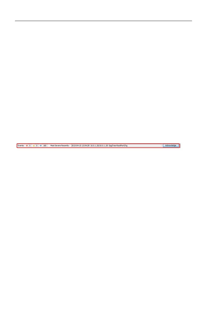
The event line contains the number of unacknowledged events in the 3
information fields after the item “Events“.
Industrial HiVision can assign one of the 3 evaluation types to an event:
Error: (red symbol)
Industrial HiVision evaluates the event that has occurred as a severe
error.
Warning: (yellow symbol)
Industrial HiVision evaluates the event that has occurred as an error that
can lead indirectly to a problem in your network.
Info: (blue symbol)
Industrial HiVision evaluates the event that has occurred as a normal
operating condition.
Figure 14: Event line - events
For every new event that occurs, Industrial HiVision increases the relevant
counter by 1. When an event is acknowledged by the user, Industrial HiVision
reduces the relevant counter by 1.
90
Interface of the program
4.4 Event line
4.4.2
Types of events
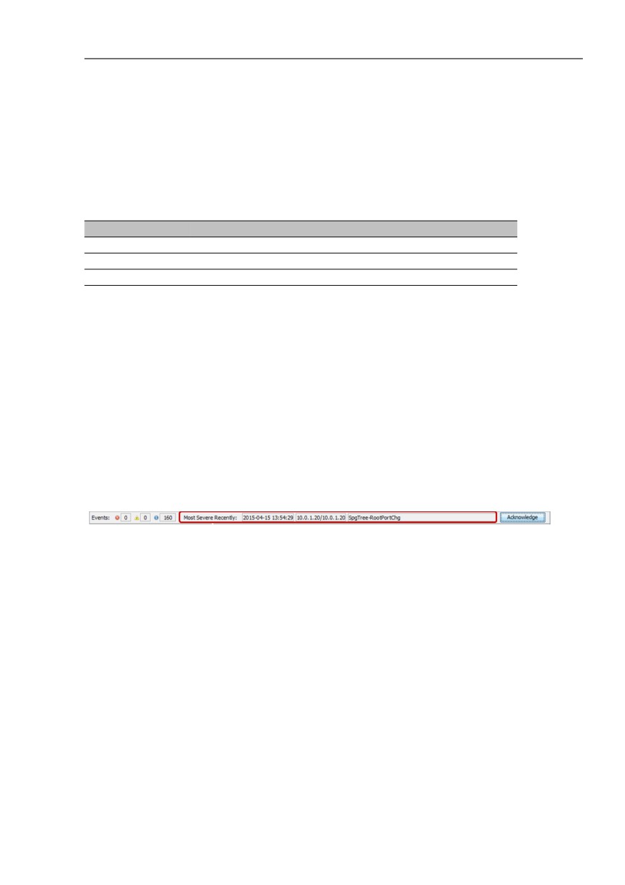
In the three information fields after the item “Most Severe Recently“, the
event line contains more detailed information on the respective event.
Designation
Meaning
Time
Date and time of the event
Source
Service for example, Industrial HiVision service
Message
Type of event for example, “New device detected by ping”
Table 3: Information on the event line
The last, most significant event is always displayed. If there is only
information, then the latest information for the relevant event is displayed. If
there are warnings too, then the latest warning for the relevant event is
displayed. If there are also errors, then the latest message for the relevant
event is displayed.
Figure 15: Event line - events - last most significant
For each new event occurring, the following is displayed:
In the “Time“ field, the related date and the time
In the “Source“ field, the name of the service which logged the event
In the “Message“ field, a detailed description of the event type
You get the full listing of every event in the “Event list” on page 112. You will
find the data from the event line in the columns of the event frame.
91

Interface of the program
4.4 Event line
4.4.3
Acknowledge events
Use the “Acknowledge“ button in the event line to acknowledge the displayed
event after you have noted it. The “Ack.“ field in the event list provides you
with another option for acknowledging events.
Figure 16: Event line - events - acknowledge
After the acknowledgment, the event line (see on page 91 “Types of events”)
displays the next event from the event log. You get the full listing of every
event in the (see on page 91 “Types of events”). Here you can also
acknowledge the relevant events in the “Ack.“ (acknowledge) column.
When an event is acknowledged by the user, the relevant counter is
decreased by 1 (see on page 90 “Number of events”).
In the “Ack.“ (acknowledge) column in the “Event list” on page 112, a green
check is set or the event is hidden after you acknowledge it, depending on
the event filter selected.
92
Interface of the program
4.4 Event line
4.4.4
Properties of an event
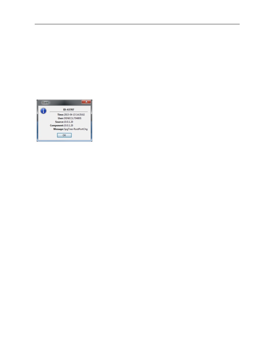
By clicking with the right mouse button on the event line and selecting
“Properties“, you open an information window with a text on the event
currently displayed.
Figure 17: Event line - Events - Properties
93
Interface of the program
4.5 Folder frame
4.5
Folder frame
In the folder frame of the Industrial HiVision program interface, you can move
around like in other standard user interfaces. See “Main window of Industrial
HiVision” on page 72. You can create new folders and move up and down
within the hierarchy using the “Back“, “Forward“ or “Up“ buttons in the tool bar
(see on page 83 “Tool bar”).
“Back“: go back to the last position
“Forward“: go forwards to the next position
“Up“: go up one level
You can also access these functions under the “View“ menu item in the menu
bar (see on page 77 “View”).
If you have divided your network into subdomains and configured them in
Industrial HiVision (see on page 53 “Network structure”), then Industrial
HiVision represents the domain structure in the top section of the folder
frame.
The folders and elements listed in the folder frame are indicated by a “+” sign
if they contain further subordinate elements or folders. To display them, you
click on this plus sign. The subordinate elements/folders are indicated by a
minus sign “-”.
To hide subordinate elements/folders again, you click on this minus sign.
94
Interface of the program
4.5 Folder frame
In its state on delivery, Industrial HiVision contains three folders:
“New Devices“
In this folder, Industrial HiVision displays the newly-detected devices.
This is part of the software and therefore cannot be deleted. Industrial
HiVision does allow you to rename the folder.
“Unused Devices“
Industrial HiVision does not monitor the devices in this folder. This folder
is part of the software and therefore cannot be deleted. Industrial HiVision
does allow you to rename the folder. In order to decrease your network
load, you can move devices which you do not need to monitor into this
folder. Industrial HiVision assigns the device status "Unmanage" to
devices in the “Unused Devices“ folder. To monitor a device again, move
the device to the desired folder.
“My Network“
Industrial HiVision provides this folder for you to create your own network
plan. You can rename or delete it and create new folders for your network
plans.
95
Interface of the program
4.6 Navigation field
4.6
Navigation field
You can use the navigation field to move around the topology display (see on
page 97 “Detail display”).
Click the navigation rectangle and pull it to the position you want within the
navigation field. Your position within the detail display changes accordingly.
See “Main window of Industrial HiVision” on page 72.
You can use the View > Zoom menu item in the menu bar, or right-click in the
navigation field, to set the enlargement of the display in the detail frame by
increments of 10%.
96