OMRON NB-Designer OPERATION MANUAL (NB-series, 2020) - page 18
6 Functions Related to External Memory
6-1-5
Recipe Data
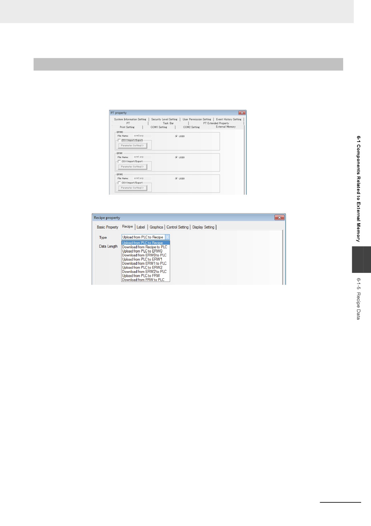
z Saving the related information into the external memory:
Select the external memory in the [External Memory] tab in the [PT Property] dialog box, as shown
below.
Later, make settings in the [Recipe] tab in the [Recipe Property] dialog box.
6
The following functions can be realized:
Upload from PLC to ERW0: Transfers the data in memory specified by PLC or controller to the ERW0
memory of the external memory.
Download from ERW0 to PLC:Transfers the data in ERW0 memory of the external memory to the
memory specified by PLC or controller.
Upload from PLC to ERW1: Transfers the data in memory specified by PLC or controller to the ERW1
memory of the external memory.
Download from ERW1 to PLC:Transfers the data in ERW1 memory of the external memory to the
memory specified by PLC or controller.
Upload from PLC to ERW2: Transfers the data in memory specified by PLC or controller to the ERW2
memory of the external memory.
Download from ERW2 to PLC:Transfers the data in ERW2 memory of the external memory to the
memory specified by PLC or controller.
6-11
6 Functions Related to External Memory
6-1-6
CSV Import / Export
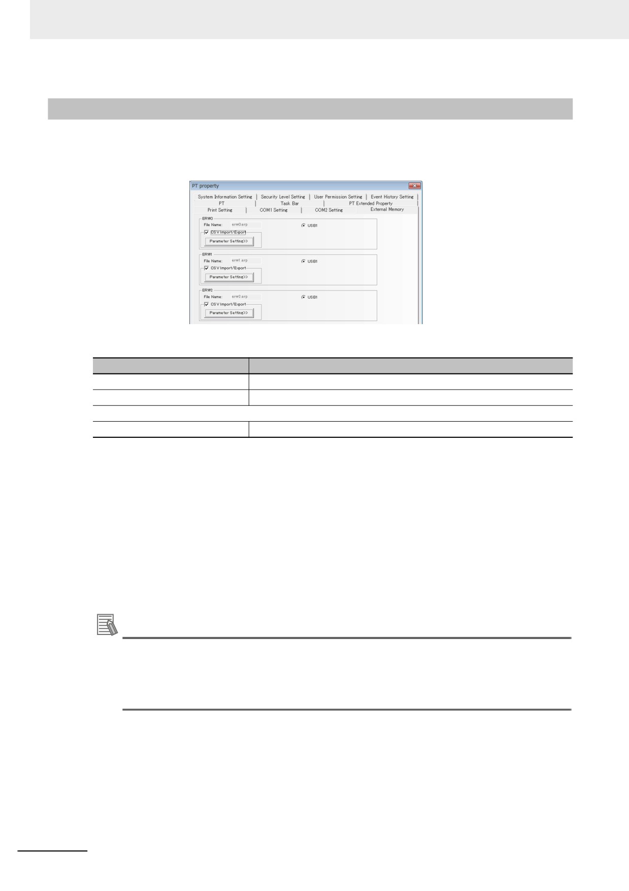
By converting data of the CSV file stored in the external memory into ERP file, the data can be handled
as ERW memory when the [CSV Import / Export] check box is checked in external memory setting.
The file names to be converted are as follows:
Names of CSV files
Address range *
ERWx_0.csv
ERWx
0
-
4194303
ERWx_1.csv
ERWx
4194304
-
8388607
:
ERWx_511.csv
ERWx
2143289344
-
2147483647
* The size of ERW memory per CSV file is 4194304 WORD.
(x=0, 1, 2)
CSV files are stored in "/exmem/[Subfolder]/ERWx_y.csv" (x=0, 1, 2, y=0 to 511). For [Subfolder]
setting, refer to 3-10-9 External Memory (Page 3-325).
• CSV file format
The CSV file format is as follows:
• Numbers, “-” (minus) , and “.” (decimal point) are supported
• Write one data for one line
• Use “LF” or “CRLF” code at the end of the line.
Additional Information
For parameter setting, refer to 3-10-9 External Memory (Page 3-325).
Specify a value using the data type that you set in [Memory Type].
If [Memory Type] is a floating-point value, exponential expressions are not supported, and non-
numeric characters like NaN are handled as error.
6-12
6 Functions Related to External Memory
6-1-7
PLC Control
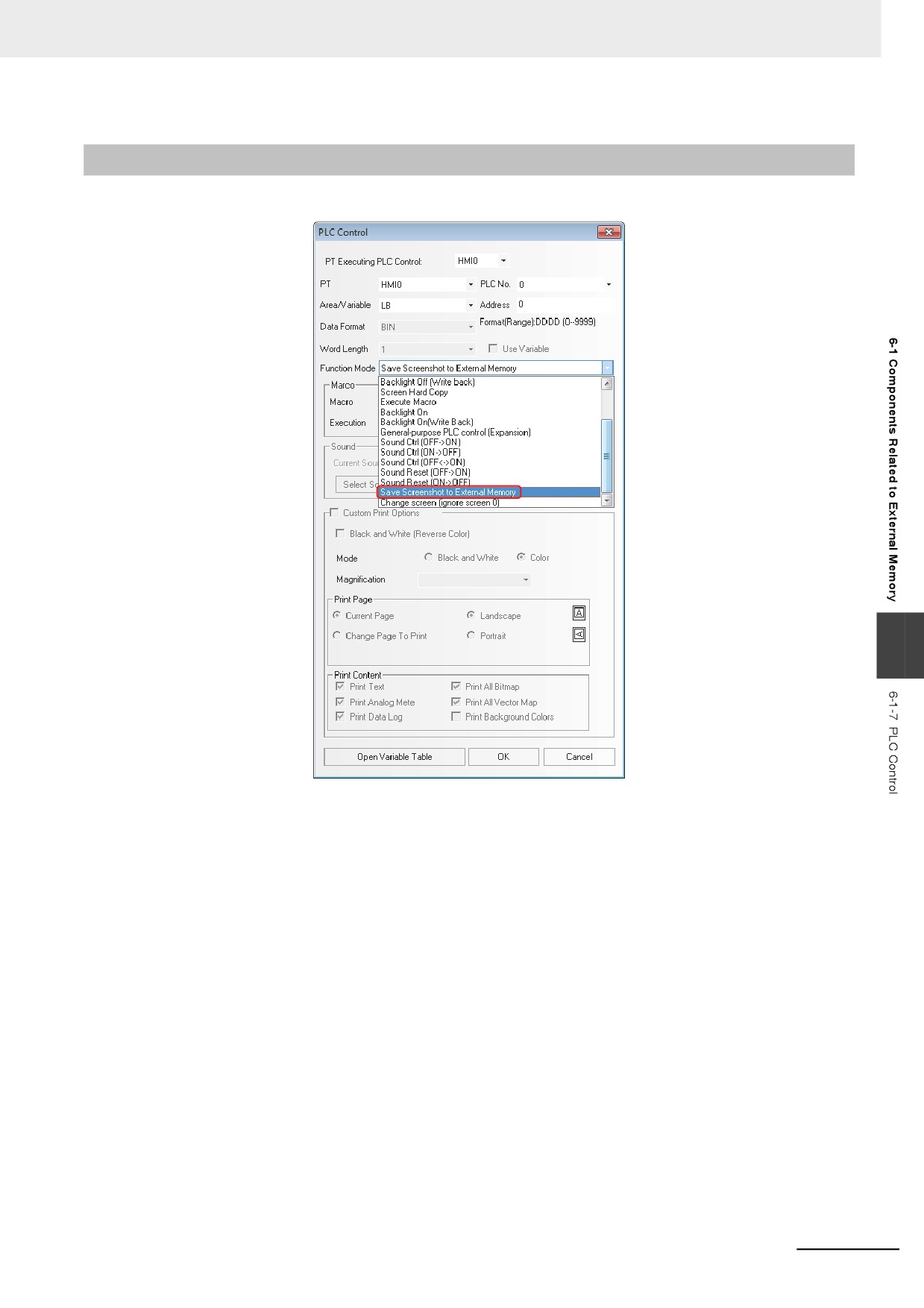
Save Screenshot to External Memory
6
For more details of “Save Screenshot to External Memory”, refer to 6-1-1 Function Key (Page 6-2).
6-13
6 Functions Related to External Memory
6-1-8
File List
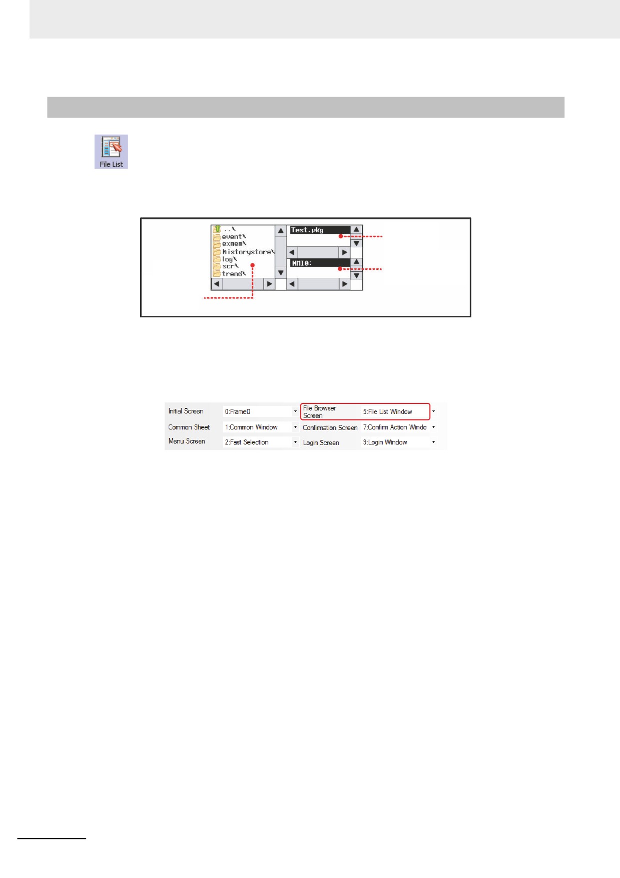
The File List is used to display the file information of the external memory. This component is
divided into three parts: the left part displays the information on the folder under the current folder, the
upper-right part displays the information on the file under the current folder, and the lower-right part
displays the PT information on the selected project file (.pkg) or the recipe file (.rcp).
Information on the file
under the current
directory
HMI information on the
Information on
selected file under the
the folder under
current directory
the current
directory
The File List component, a kind of special component, needs to be used in combination with
[Import/Export] function of Function Key.
[Frame5:File List Window] is generated automatically when the new project is created, convenient for
the users to call it during the import or export of project file or recipe file. The specified pop-up File
Browser Screen can be set in the [PT Extended Properties] tab in the [PT Property] dialog box.
6-14
6 Functions Related to External Memory
6-1-9
FTP Server
Upon request from the PC, FTP server transfers files in the external memory, which is inserted to the
NB Unit, to the PC connected through Ethernet. This function only supports the models with Ethernet
port and USB HOST. For settings, refer to 3-10-1 PT (Page 3-291).
To use FTP server function, make the connection from the PC with the following settings.
Server: IP Address of the NB Unit
User name: root
Password: The value set in PT property setting
Port: 21
Additional Information
• This function can be enabled or disabled by changing the value of LB9296 on the NB Unit.
• By enabling FTP server, the NB Unit will be exposed to risk of attacks from external networks.
Before enabling FTP server, you need to take security measures to prevent attacks from
external networks and to minimize the possible damage.
• NB's FTP server function supports functions defined by RFC959. It does not ensure connec-
tions with all the FTP clients due to unsupported extended commands or options. Test con-
nections with an actual device before use.
6
6-15
PictBridge Printing
This section describes the PictBridge printing function.
7-1
PictBridge Function
7-2
7-2
Setting Method for Using Printing Function
7-4
7-3
Components Related to Printing and Setup Descriptions
7-6
7-3-1
PLC Control
7-6
7-4
List of System memories Related to Printing
7-8
7-5
List of Error Codes for Printing
7-9
7-6
Recommended Printer Models
7-10
7
7-1
7 PictBridge Printing
7-1
PictBridge Function
PictBridge is the industry standard for direct printing with the device and a printer directly connected.
This standard enables digital images from the device to be printed directly by a printer, eliminating the
need of connecting the device to a PC, thus greatly facilitating the printing process in various
conditions.
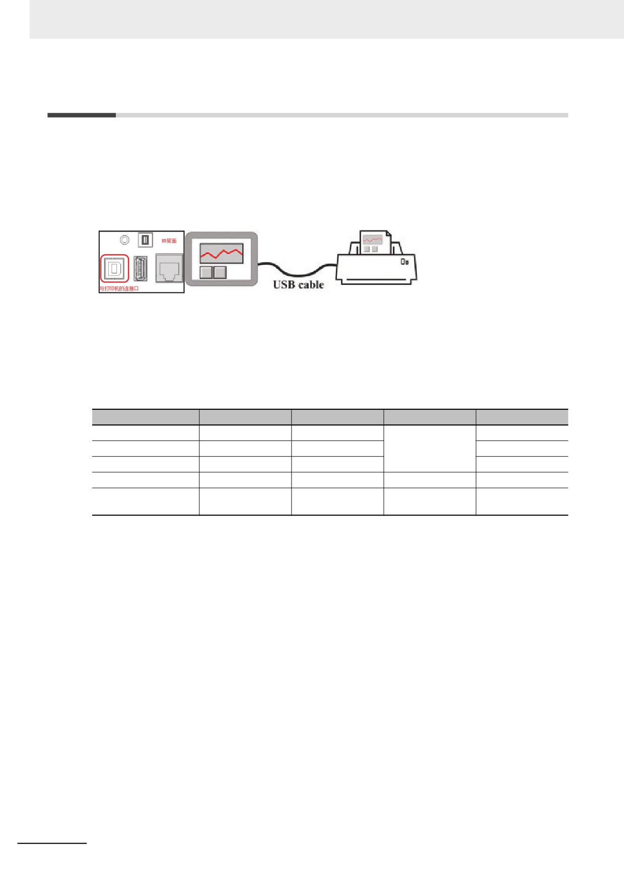
The NB series touch panel supports the PictBridge protocol, and connected to such a printer with the
USB Slave port, it can perform printing of images and other data.
In order to use the PictBridge function, it is necessary to update the Kernel and Rootfs in NB-Designer
Ver. 1.2.2 or later. For the update method, refer to 4-4 System Operation (Page 4-15) in NB-Designer
Operation Manual.
When downloading project from NB-Designer or transferring project from the USB to the NB Unit, if the
message of “Please update the Kernel and Rootfs in the NBManager.” is displayed, it means user
should update the NB Kernel and root file system.
Version information list
NB-Designer
Kernel
Rootfs
Is necessary to update?
Enable Print
Ver. 1.10
1317
1337
Necessary
-
Ver. 1.20
1317
1389
-
Ver. 1.21
1317
1389
Checked by default
Ver. 1.22
1458
1517
Unnecessary
Checked by default
Determined by the
Unchecked by
Ver. 1.23 or later
1458
1548
user project *
default
* If the printing function is not required, the user should uncheck the “Enable Printing” before opening
the previous project with the NB-Designer version 1.23. Then recompile and download the project.
7-2
7 PictBridge Printing
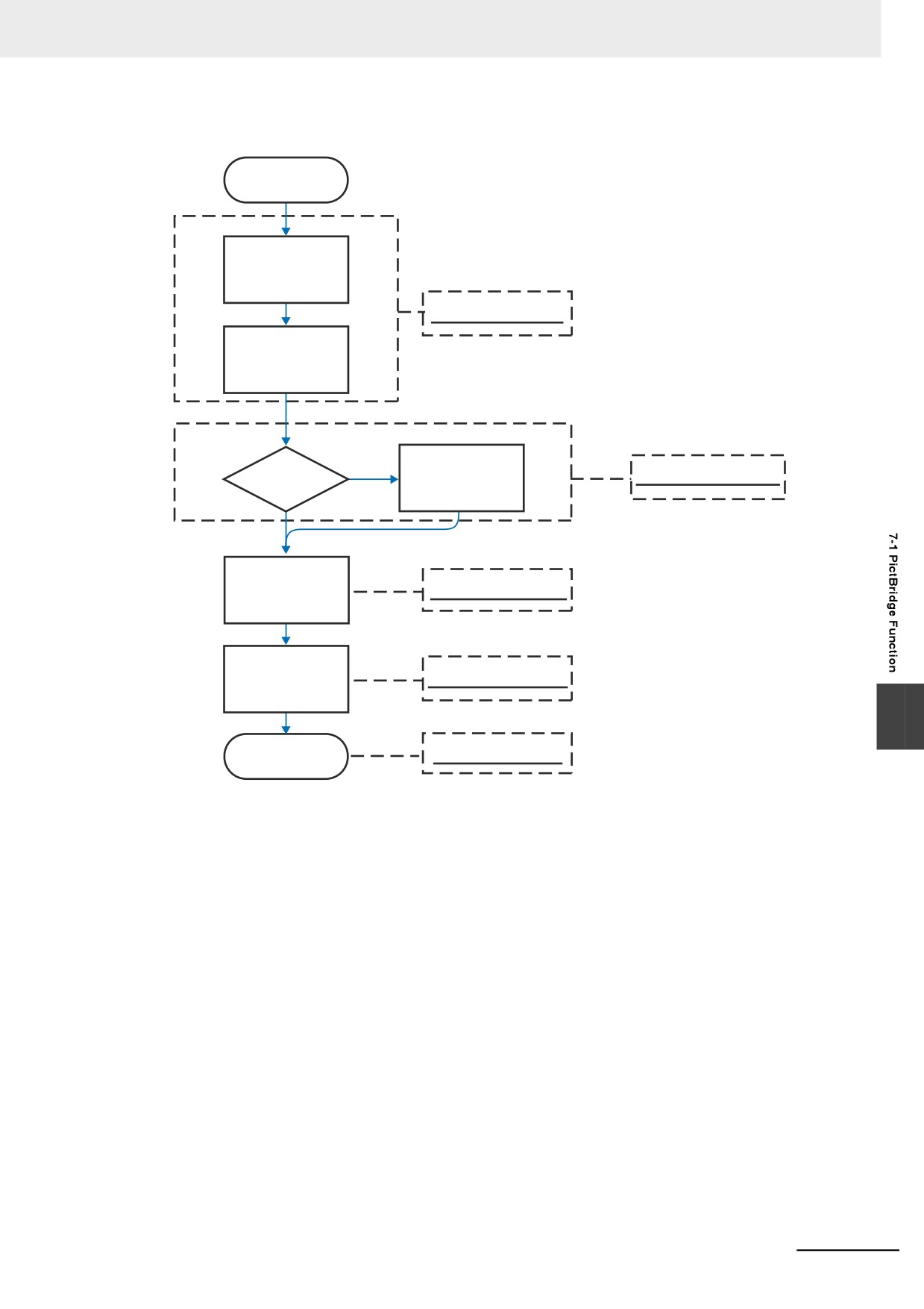
z The printing function updates flow chart
Start
Update Kernel
Downloader Mode
Update Rootfs
Disable Printer
Is print function
System Setting Mode
disabled?
N
Function
Y
Download
User Project Mode
Project
Enable Printer
System Setting Mode
Function
7
Printer is
User Project Mode
Available
7-3
7 PictBridge Printing
7-2
Setting Method for Using Printing
Function
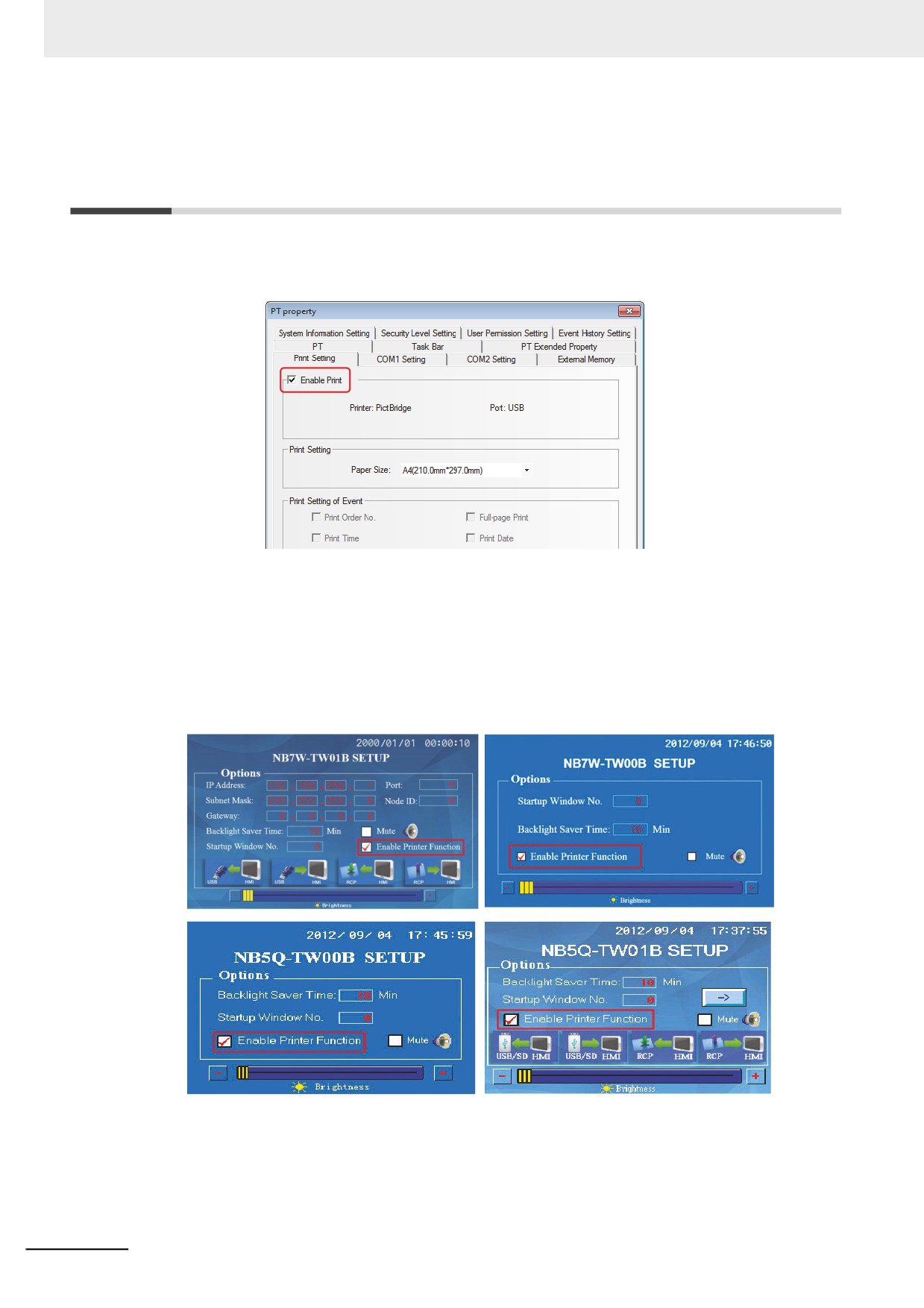
1 After the project being completed, compile it with the [Enable Print] option in the [Print Setting]
tab in the [PT Property] dialog box being checked.
2 Set the DIP switches SW1 and SW2 on the back side both to ON. Then press the Reset switch,
and restart the NB Unit to enter the System Setting Mode. Then download project to the NB Unit
after the compilation is completed.
3 Check the “Enable Printer Function” option to enable the printing operation.
The locations of “Enable Printer Function” in the System Setting Mode for different PTs (NB10W
is the same as NB7W, and NB3Q is the same as NB5Q.) are shown as follows:
4 Set the DIP switches SW1 and SW2 both to OFF, and restart the NB unit to enter the User
Project Mode.
5 Use the USB cable to connect the USB Slave port on the back side of NB Unit with the printer
for printing.
7-4
7 PictBridge Printing
Note 1
The USB slave port on NB Unit is used for the upload/download and commissioning of program by
default, but in the User Project Mode, it will shift to a USB port only supporting the printing function
instead of other functions when the “Enable Print” option in the System Setting Mode is checked.
2
In the Downloader Mode or System Setting Mode, the function of using USB Slave port to download
always works properly without the influence of the above settings.
3
If the printer cannot work normally as a result of the NB Unit power-on, reset or other operations,
please restart the printer.
4
When the printing function cannot be used, refer to 6-3-1 Software Trouble in the NB Series Startup
Guide Manual for the solution.
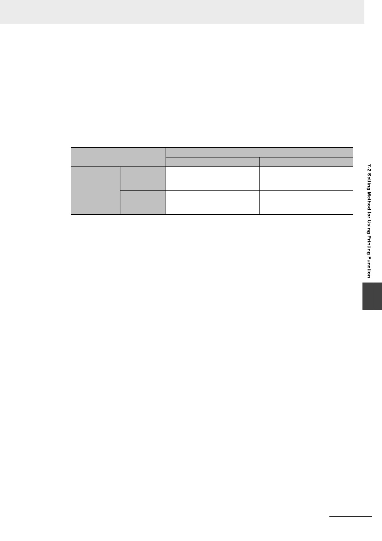
z The descriptions of USB Slave port in the User Project Mode:
[Enable Print] (set in the NB-Designer)
Setting Items
Checked
Unchecked
USB slave port is only for printing.
Since the project is not set in
[Enable Printer
Checked
printing mode, printing is not
Function] (set
available.
in the System
USB slave port can’t be used for
Since settings of the NB unit and
Setting Mode)
Unchecked
printing because it is in download
the project are not set in printing
mode.
mode, printing is not available.
In conclusion, the printing is available only after the printing function in NB-Designer and NB Unit
are both enabled.
7
7-5
7 PictBridge Printing
7-3
Components Related to Printing and
Setup Descriptions
z Related Components List
Component name
Function
Trigger address
Print contents
PLC Control
Screen Hard Copy
Bit
Prints the current screen
7-3-1
PLC Control
z Screen Hard Copy
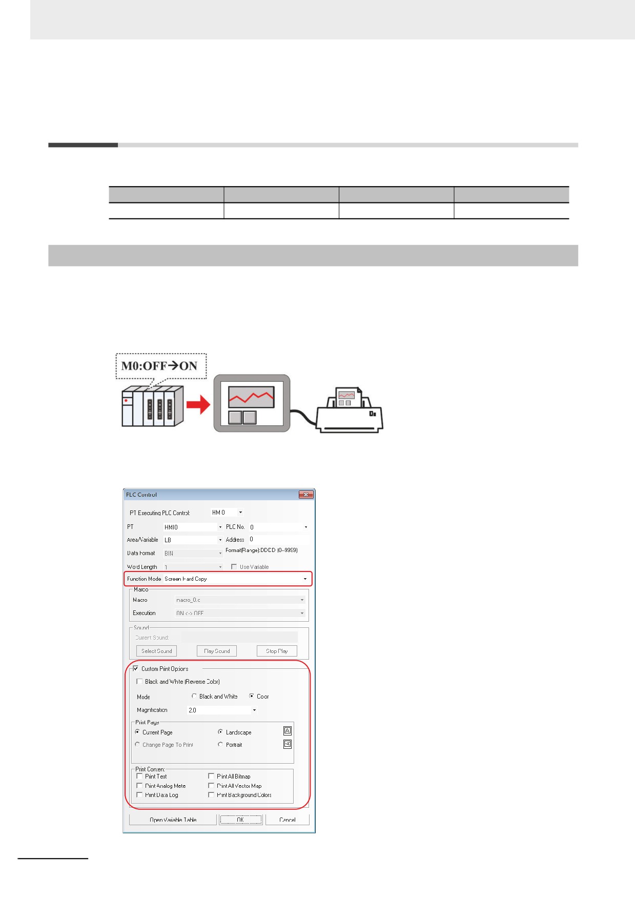
Screen Hard Copy is to control the printout of the current screen allocated to the bit address of PLC
control. When the address of the specified memory is turned from OFF to ON, the current screen
contents will be printed out.
The print content output mode setting:
Method 1: Check [Custom Print Options].
7-6
7 PictBridge Printing
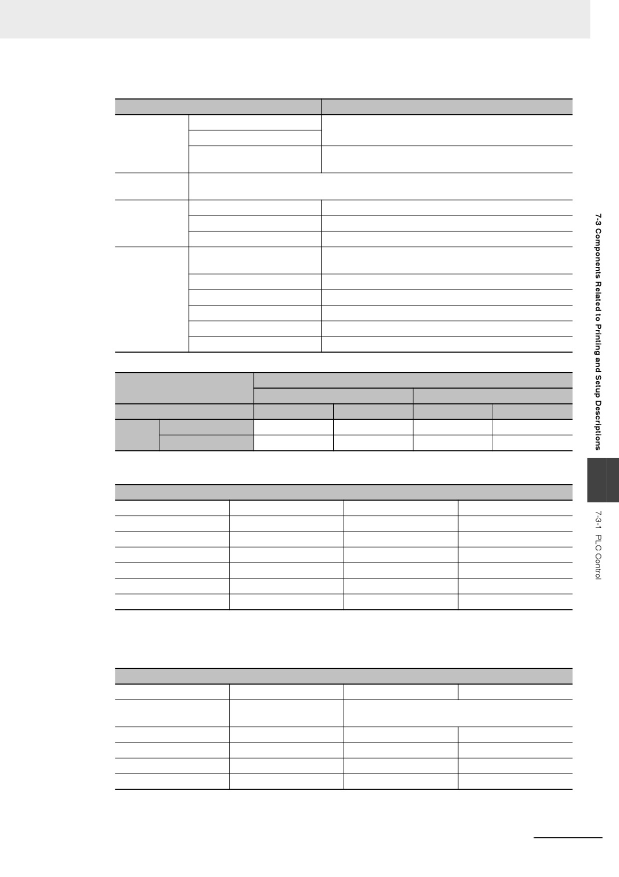
Custom Print Options Properties Description:
Custom Print Options Properties
Details
Printer Color
Black and White
Only color printers support printer color change.
Color
Black and White
Prints the monochrome in reverse color.
(Reverse Color)
Magnification
It can be selected from 0.1 to 5.0 (Zoom Out printing may cause distortion, thus is not
recommended.)*
Print Page
Current Page
Print the current screen.
Landscape
print the content with landscape orientation.
Portrait
print the content with portrait orientation.
Print Content
Print Text
Prints the static texts and label characters on the current
screen.
Print Analog Meter
Prints the Analog Meter components on the current screen.
Print Trend Graph
Prints the Trend Graph on the current screen.
Print All Bitmap
Prints all the Bitmaps on the current screen.
Print All The Vector Map
Prints all the Vector Graphics on the current screen.
Print Background Colors
Prints the background color of the current screen.
* Default Magnification (based on standard A4 paper):
PT Model
NB3Q/NB5Q -TW
B
NB7W/NB10W-TW
B
Print Direction
Landscape
Portrait
Landscape
Portrait
Display
Horizontal Display
4
3
2
1.4
Mode
Vertical Display
3
4
1.4
2
Method 2: Don't check Custom Print Options, and make the setting through the corresponding bits
of the system memories LW9054 and LW9055.
7
Lw9054 Settings
Bit No.
Name
0 (The bit is OFF)
1 (The bit is ON)
Bit 0
Print Text
Not print
Print
Bit 1
Print Analog Meter
Not print
Print
Bit 2
Print Trend Graph
Not print
Print
Bit 3
Print All Bitmap
Not print
Print
Bit 4
Print All The Vector Map
Not print
Print
Bit 5
Print Background Colors
Not print
Print
The value of LW9054 can be set with the Command Button component. If all contents on the PT
screen are to be printed, place the Command Button component to the Common Sheet. Select [Set
value when screen is loading] in the [Command Button] tab of the [Command Button Property],
specify [Set Value] to “255”, and specify LW9054 to a value allow all the content printed.
Lw9055 Settings
Bit No.
Name
0 (The bit is OFF)
1 (The bit is ON)
Bit 0~ Bit 7
Magnification
Ranges from 1 to 50 with the meaning of magnifying
0.1 to 5.0 times respectively.
Bit 8
Printer Color
Color
Black and White
Bit 9
Print Page
Prints the current page
System Reserved
Bit 10
Print Direction
Landscape
Portrait
Bit 12
Reverse Color Print
Normal Print
Reverse Color Print
[Example] To print the content in the current page with a magnification of 0.3 in monochrome, set
LW.B9055.0, LW.B9055.1 and LW.B9055.8 all ON, and LW.B9055.9 OFF; or set LW9055 to “259”.
7-7
7 PictBridge Printing
7-4
List of System memories Related to
Printing
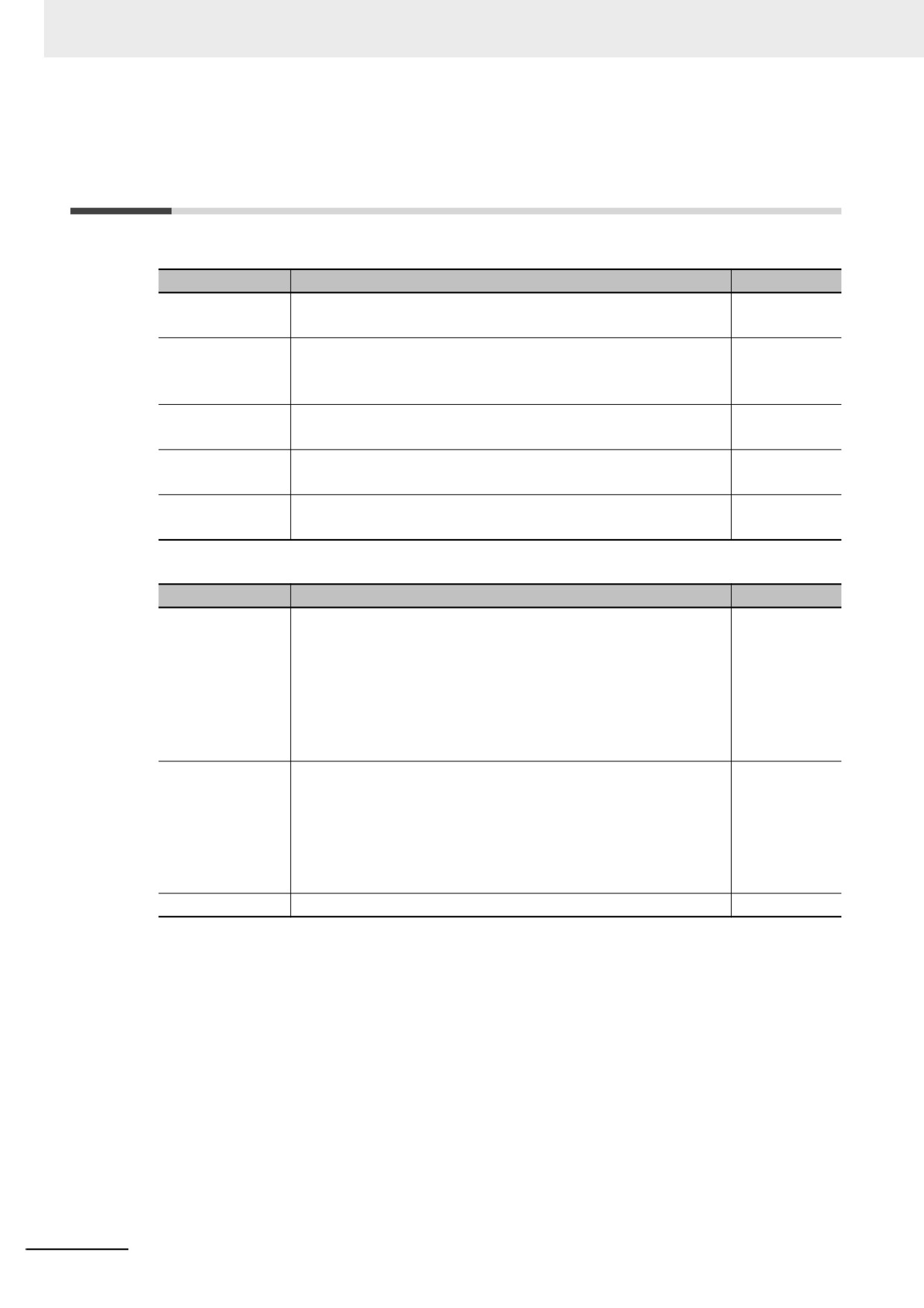
Local Bit (LB):
Address
Function description
Property
LB9016
Printer error indication.
Read only
ON: Error; OFF: Normal
LB9017
Printer control mask bit
Read /Write
ON: Disable; OFF: Enable (default).
All the print modes will be invalid when this bit is ON.
LB9132
Printer state.
Read only
ON: Busy; OFF: Idle.
LB9133
Pretreat for improve print effect.
Read /Write
ON: Pretreat; OFF: Direct Printing.
LB9143
USB printer connection status.
Read only
ON: Connect; OFF: Disconnect.
Local Word (LW):
Address
Function description
Property
LW9054
Printout format
Read/Write
Bit0: Text
0: not print; 1: print
Bit1: Analog Meter 0: not print; 1: print
Bit2: trend graph 0: not print; 1: print
Bit3: all bitmaps
0: not print; 1: print
Bit4: all vector Map
0: not print; 1: print
Bit5: Background Color 0: not print; 1: print
LW9055
Printout format
Read/Write
Bit0~Bit7: 1~50 show magnification 0.1~5.0
Bit8: Printer Color
0: Color; 1: Black and White
Bit9: Print Page 0: current page; 1: System Reserved
Bit10: Printer Directing
0: Landscape; 1: Portrait
Bit12: Reverse Color Enable 0: Normal; 1:Reverse
LW9800&LW9801
Current Error Codes
Read/Write
7-8
7 PictBridge Printing
7-5
List of Error Codes for Printing
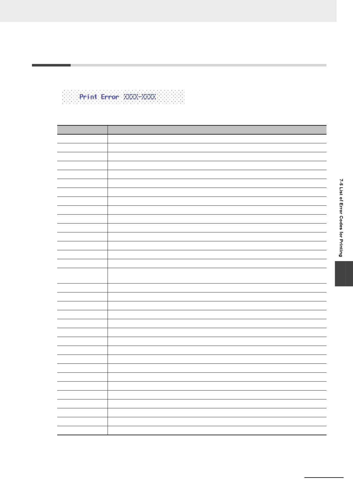
When the printing has some problems, error will occur in the system with the error codes displayed.
The error codes displayed include the following codes. The error codes will be displayed the PT screen
and stored in the system memory (lower words) and LW9801 (higher words).
Codes (Value)
Description
0x73000000
Normal status (default).
0x7300FFF9
Printer not ready
0x7300FFFA
Printer busy (Trigger another print job when printer is printing)
0x7300FFFB
Driver & UI Printer Settings Disable
0x7300FFFC
UI Printer Setting Disable
0x7300FFFD
USB Cable not Connect
0x7300FFFE
Others Reason
0x7300FFFF
Driver is not configured
0x73010000
Paper related error (default).
0x73010100
Paper is empty.
0x73010200
Load Error - paper not loaded correctly.
0x73010300
Eject Error - paper not ejected correctly.
0x73010400
Media Error - paper not detected, paper skewed, roll paper cannot be cut or torn-off.
0x73010500
Paper jam.
0x73010600
Paper nearly empty.
0x73010700
The combination of paper type and paper size is not supported, or paper set in Printer does
7
not match request.
0x73020000
Ink related reason (default).
0x73020100
Ink empty.
0x73020200
Ink low.
0x73020300
Waste ink error (waste-ink reservoir full).
0x73030000
Hardware-related error. (default)
0x73030100
Fatal error.
0x73030200
Service call.
0x73030300
Printer unavailable (performing maintenance or processing jobs).
0x73030400
Printer buffer memory full.
0x73030500
Lever error (lever position not correct).
0x73030600
Cover open.
0x73030700
No print unit (e.g., missing print head).
0x73030800
Ink Cover open.
0x73030900
No ink Cartridge.
0x73040000
File-related error. (default)
0x73040100
Printinfo error (the size of information set to <Printinfo> is too large.)
0x73040200
File decode error (picture format of specified image cannot be decoded).
7-9
7 PictBridge Printing
7-6
Recommended Printer Models
Brand
Model
CANON
PIXMA iP4980
EPSON
Colorio PX-G5300
HP
HP 8500A, HP 8500A Plus
7-10
Web Interface
This section describes Web Interface.
8-1
Defining Web Interface
8-2
8-2
Setup Web Interface on a PC
8-3
8-3
Connection Method and Each Page Function
8-4
8-4
URL List
8-10
8
8-1
8 Web Interface
8-1
Defining Web Interface
NB Series Programmable Terminal provides Web Interface function which is accessible externally with
the use of a Web browser. Using Web Interface function allows monitoring and operating the NB Unit
screens from external device.
Precautions for Correct Use
Security of this function is subjected only to Password. Give due consideration to Network
configurations and exclude illegal access to accomplish the security.
In the Monitor mode, a password is not set initially. Set a password before you use the function,
if necessary.
In order to use the Web Interface function, you shall update PT kernel and Rootfs in the NB-Designer
Ver.1.30 or later. For the update method, refer to the 4-4 System Operation (Page 4-15).
• Targeted Model
NB -TW01B
• Targeted Version
NB-Designer: V1.30 or later
Kernel: 1764 or later
Rootfs: 1932 or later
• Operation confirmed Web browser
Internet Explorer 8 (Windows)
Internet Explorer 9 (Windows)
Google Chrome 32.0.1700.107 m (Windows) *1
Firefox 27.0 (Windows)
Safari (iOS6)
*1
Uncheck the check box of Use JavaScript in Server Setting.
Additional Information
Select the compatibility display when browsing it with Internet Explorer 10 or later.
8-2
8 Web Interface
8-2
Setup Web Interface on a PC
Perform following settings beforehand in order to use Web Interface function.
z Setting User Name and Password for Web Interface function
Set the User Name and Password for using this function. For the details, refer to the 4-8 Web Inter-
face Operation (Page 4-20).
z Enable Web Interface function
In order to enable the Web Interface function, embed the function which turns LB9175 ON to the
project. Additionally, the LB9175 setting is applied immediately. Restart is not necessary.
Additional Information
NB Web interface function establishes communication by conforming to HTTP 1.0. The session-
retaining function with the Keep alive function is not supported. A session begins per command.
Thus, the number of units that are connected concurrently is not limited.
However, when more than one PC are connected, a PC needs to wait until other PC processing
is done. Thus, response may become slow.
8
8-3
8 Web Interface
8-3
Connection Method and Each Page
Function
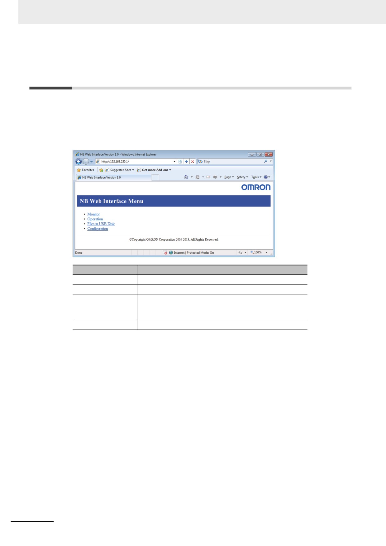
In order to access the NB Unit with the use of the Web browser, access http://[the NB Unit IP address]/. Initial
display of screen may be changed according to setting. However, Menu page is displayed in factory setting.
• Menu page
It is a page displayed by default at the time of shipment. Through this page, it is accessible to each
page.
Function Name
Details
Monitor
It displays a monitoring page.
Operation
It displays an operation page.
Files in
It displays a file list in the USB Disk that mounts to the NB
USB Disk*1
Unit. Displaying the file contents and downloading the file
are available on Web browser.
Configuration
It displays a configuration page.
*1: Kernel 1764 or RootFS 2102 or higher is required.
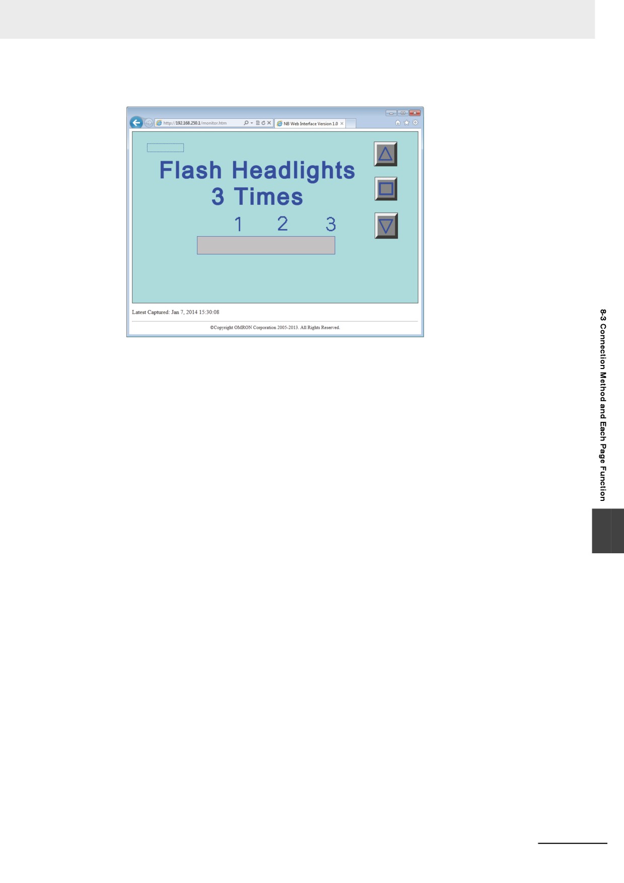
• Monitoring page
8-4
8 Web Interface
It is a page to refer to the screen which is currently displayed on the NB Unit. A screen is updated at the inter-
val according to the setting. The screen displayed is not available to be operated with the monitoring page.
8
8-5
8 Web Interface
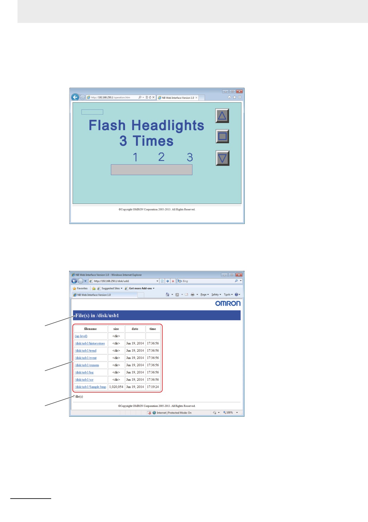
• Operation page
It is a page to operate the screen which is currently displayed on the NB Unit.
A screen is updated at the interval according to the settings. The screen displayed is available to
operate with the operation page.
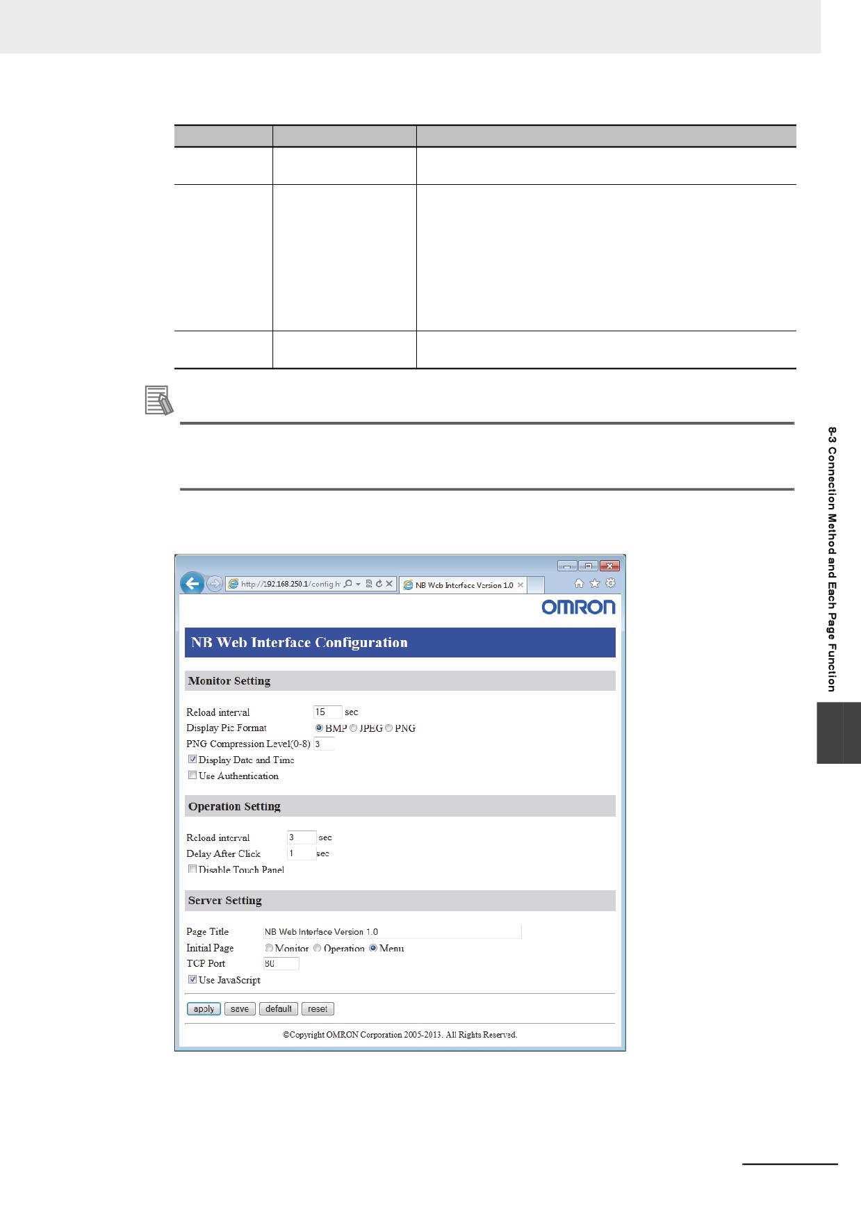
• Files in USB Disk page
(1) File in the USB Disk page
The page of Files in USB Disk allows a file list of the USB Disk that mounts to the NB Unit
to be displayed. Also the page provides functions to display files on the file list and to down-
load such files with Web browser.
a
b
c
8-6
8 Web Interface
No
Item
Description
a
Folder
It displays the folder in the current USB Disk. The root folder of
the USB Disk is referred as "/disk".
b
File List
It displays a file list below the current folder.
In addition to the common usages of Web browser, it allows the
file contents to be displayed or the file to be downloaded.
The cells displayed with <dir> in the 'size' column indicates the
folders.
When you move from a folder to another one, click on the folder
name in the destination. When you move to the upper folder,
click on the (up level).
c
Total number of files
It displays total number of the files and folders that are currently
displayed.
Additional Information
Types of files to display directly are varied according to the Web browser. For any files that
cannot be displayed directly, it should be displayed with an appropriate application after
downloading the file once or install a plug-in or other.
• Configuration page
It is a page to perform setting regarding Web Interface.
8
8-7
8 Web Interface
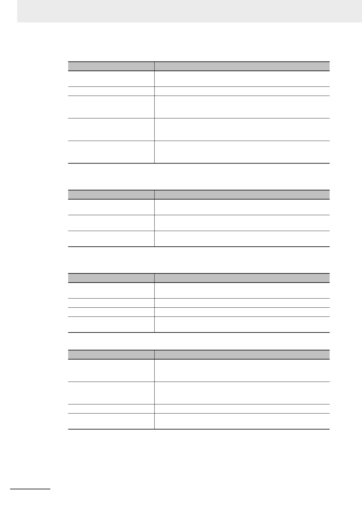
•
Monitor Settings
Settings
Details
Reload Interval
Set refresh interval of Monitoring page display in the range between 2
and 99 sec.
Display Pic Format
Set format of a picture.
PNG Compression Level
Specify compression rate in the range between 0 and 8 when the
picture format is designated to PNG. As the number is greater, the
compression rate becomes higher.
Display Date and Time
When you need to display the date and time on the Monitoring page for
what you have obtained a screen, put a check in the checkbox of this
setting.
Use Authentication
When you directly specify URL for monitoring page followed by
perform user authentication, put a check in the checkbox of this
setting.
•
Operation Settings
Settings
Details
Reload Interval
Set refresh interval of Operation page display in the range between 2
and 99 sec.
Delay After Click
Set waiting time to request next picture after clicking the screen on
Web browser.
Disable Touch Panel
Put a check in the checkbox of this setting when you need to prohibit
the operation of the NB Unit on Web browser.
•
Server Settings
Settings
Details
Page Title
Set page title less than 64 characters. It supports only single-byte
alphanumeric characters.
Initial Page
Set the page displayed by default.
TCP Port
Set Port No. of TCP.
Use JavaScript
Put a check in the checkbox when you use JavaScript for refresh
processing of screen.
Functions
Details
Apply
The setting is applied by choosing this function. The setting data which
is applied with apply will be restored to the state before pressing apply
when the NB Unit is restarted.
Save
The setting is stored to and is applied to the NB Unit. The setting data
which is applied with save will be retained even though the NB Unit is
restarted.
Default
All the setting data will be restored to the state of factory setting.
Reset
All the setting data will be restored to the state before applying
changes.
8-8
8 Web Interface
Additional Information
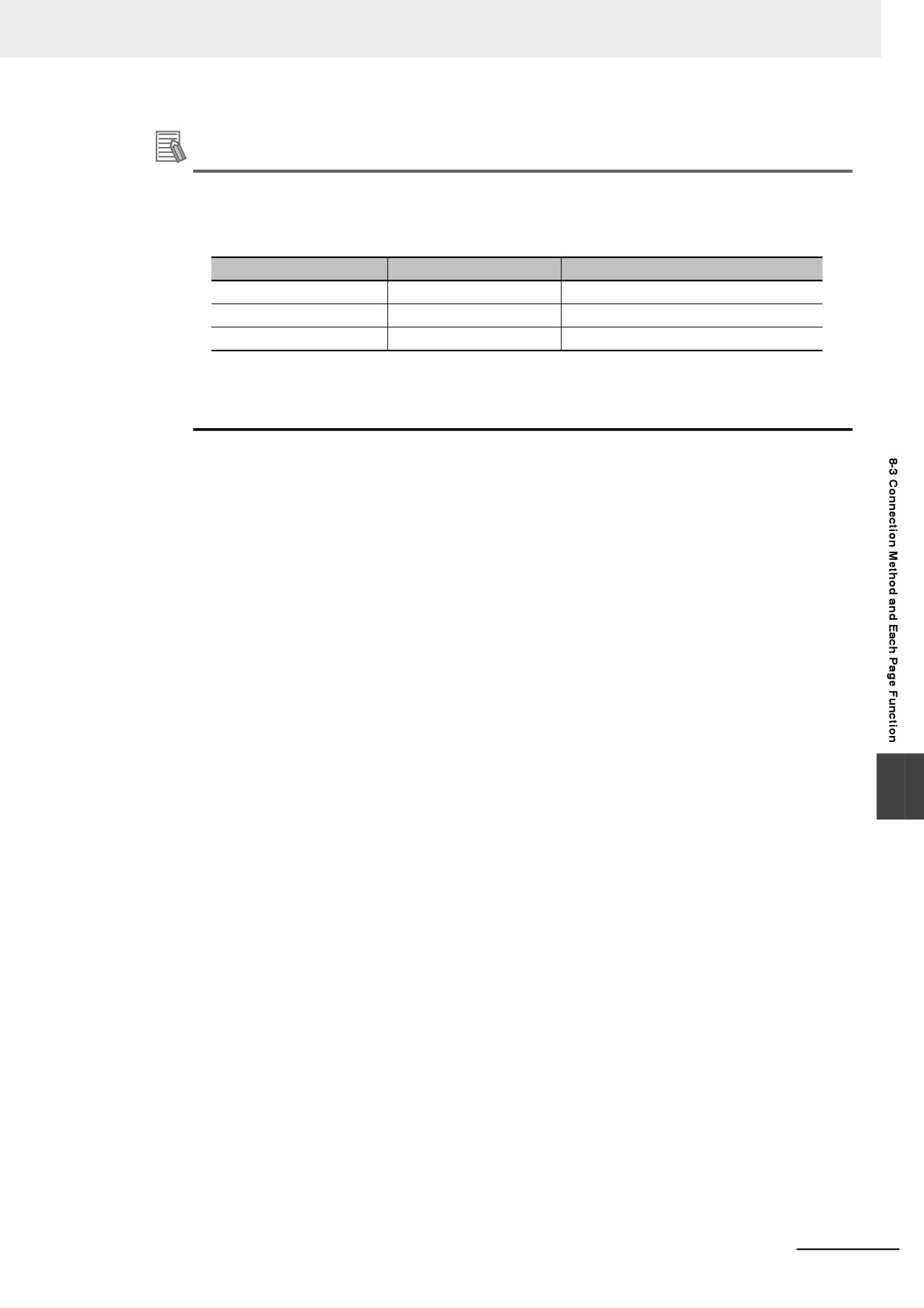
• The following characteristics are provided for the graphic formats which are selectable by Dis-
play Pic Format.
As the size of the graphics become larger, it takes longer to transfer the graphics. Then it
takes longer to refresh the screen. In accordance with the situations, select the optimal format.
Quality
Size
BMP
Fine
Large
JPEG
Bad
Small
PNG
Fine
Rather Large
• If Reload interval is too short, the transferring may be too late for displaying the graphic cor-
rectly.
Set the value in which should be considered the status of transferring pathway and others.
8
8-9
8 Web Interface
8-4
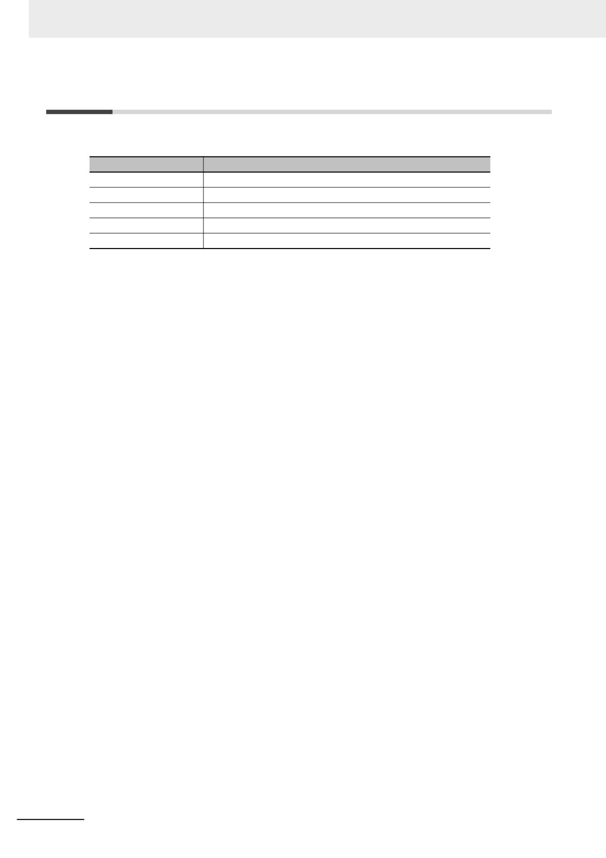
URL List
Accessing the following URL when you use Web Interface allows you to access directly each page.
Page name
URL
Menu page
http://[the NB Unit IP address]/menu.html
Monitoring page
http://[the NB Unit IP address]/monitor.html
Operation page
http://[the NB Unit IP address]/operation.html
Files in USB Disk page
http://[the NB Unit IP address]/usbdisk.html
Configuration page
http://[the NB Unit IP address]/config.html
8-10
pp
Appendices
A-1 List of Models
A-2
A-2 NB-Designer Function List
A-6
A-3 List of memories supported by OMRON PLC
A-11
A-4 Usage of Forced Address Bit
A-16
A-1
Appendices
A-1
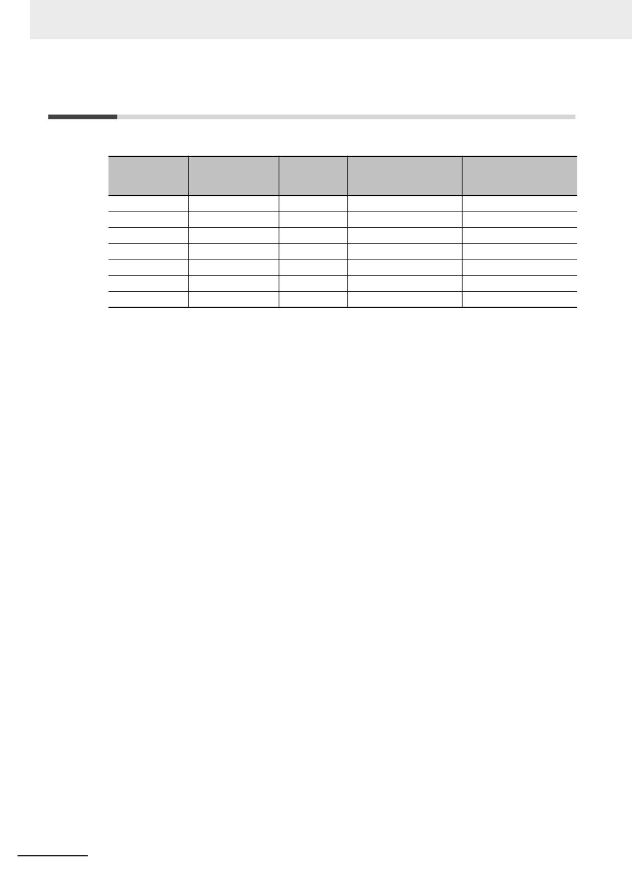
List of Models
z NB Unit
USB
Models
Resolution
Size
Communication
(Equivalent of USB 2.0
Full Speed)
NB3Q-TW00B
QVGA 320×240
3.5 inches
COM1
Slave
NB3Q-TW01B
QVGA 320×240
3.5 inches
COM1, Ethernet
Host, Slave
NB5Q-TW00B
QVGA 320×234
5.6 inches
COM1, COM2
Slave
NB5Q-TW01B
QVGA 320×234
5.6 inches
COM1, COM2, Ethernet
Host, Slave
NB7W-TW00B
WVGA 800×480
7 inches
COM1, COM2
Slave
NB7W-TW01B
WVGA 800×480
7 inches
COM1, COM2, Ethernet
Host, Slave
NB10W-TW01B
WVGA 800×480
10.1 inches
COM1, COM2, Ethernet
Host, Slave
A-2
Appendices
z
Units at the host side which can be connected using the serial port of the NB
Unit in the RS-232C mode through Host Link
PLC
CPU Unit with built-in Host
Through Serial Communication
Options required for
Series
Link function
units/boards
connection
CP Series
CP1L-L14/L20/M30/M40/M60
CP1W-CIF01
CP1H-X40/XA40/Y20
CP1W-CIF01
CP1E-N14/N20
CP1E-N30/N40/N60/NA20
CP1E-N30/N40/N60/NA20
CP1W-CIF01
CP1L-EL20/EM30/EM40
CP1W-CIF01
CP2E-E14/E20/E30/E40/E60
CP2E-N14/N20/N30/N40/N60
CP1W-CIF01
CP2E-S30/S40/S60
CP2W-CIFD1/CIFD2
(*3)
C Series
C200HE-CPU42
C200HE-CPU32/42
C200HW-
C200HE-CPU42-Z
C200HE-CPU32/42-Z
COM02/04/05/06-V1
C200HG-CPU43/63
C200HG-CPU33/43/53/63
C200HW-
C200HG-CPU43/63-Z
C200HG-CPU33/43/53/63-Z
COM02/04/05/06-V1
C200HX-CPU44/64
C200HX-CPU34/44/54/64
C200HW-
C200HX-CPU44/64/65/85-Z
C200HX-CPU34/44/54/64/65/85-Z
COM02/04/05/06-V1
CPM1-10/20CDR-
+CPM1-CIF01
CPM1A-10/20/30/40CD
-
+CPM1-CIF01
CPM2A-30/40/60CD
-
+CPM1-CIF01
(When a peripheral port is
connected)
CPM2C-10/20
-
(*1)
CQM1H-CPU11/21/51/61 (*2)
CQM1H-CPU51/61
CQM1H-SCB41
CS Series
CS1G-CPU42/43/44/45 (-V1)
CS1G-CPU42/43/44/45 (-V1)
CS1W-SCU21 (-V1)
CS1H-CPU63/64/65/66/67 (-V1)
CS1H-CPU63/64/65/66/67 (-V1)
CS1W-SCB21/41 (-V1)
CS1G-CPU42H/43H/44H/45H
CS1G-CPU42H/43H/44H/45H
CS1W-SCU21 (-V1)
CS1H-
CS1H-CPU63H/64H/65H/66H/67H
CS1W-SCB21/41 (-V1)
CPU63H/64H/65H/66H/67H
CJ Series
CJ1G-CPU44/CPU45
CJ1G-CPU44/CPU45
CJ1W-SCU21/41/-V1
CJ1G-CPU42H/43H/44H/45H
CJ1G-CPU42H/43H/44H/45H
CJ1W-SCU21/41/-V1
CJ1H-CPU65H/66H/67H
CJ1H-CPU65H/66H/67H
CJ1M-CPU11/12/13/21/22/23
CJ1M-CPU11/12/13/21/22/23
CJ1W-SCU21/41/-V1
CJ2M-CPU31/32/33/34/35
CP1W-CIF01
CJ2M-CPU11/12/13/14/15
CJ2H-CPU64/65/66/67/68(-EIP)
NJ Series
NJ501/301/101
CJ1W-SCU22/42
NX Series
NX1P2
NX1W-CIF01
*1:
Connect using conversion cables (CPM2C-CN111 type or CS1W-CN114/118 type), the RS-232C adaptor
(CPM1-CIF01 type) or the RS-422A adaptor (CPM1-CIF11 type).
*2:
The CQM1H-CPU11 model does not have the RS-232C port built in the CPU, therefore it requires a peripheral
port to be connected to a PT through a conversion cable (CS1W-CN118 type).
*3:
CP2W-CIFD1 option board has 2 RS-232C serial ports with different protocols. Connection with NB HMI is
available only through Port 1.
A-3
Appendices
z Units at the host side which can be connected using the serial port of the NB
Unit in the RS-422A mode through Host Link
CPU Unit with built-in Host
Through Serial Communication
Options required for
PLC Series
Link function
units/boards
connection
CP Series
CP1L-L14/L20/M30/M40/M60
CP1L-L14/L20/M30/M40/M60
CP1W-CIF11/CIF12
CP1H-X40/XA40/Y20
CP1H-X40/XA40/Y20
CP1W-CIF11/CIF12
CP1E-N30/N40/N60/NA20
CP1E-N30/N40/N60/NA20
CP1W-CIF11/CIF12
CP1L-EL20/EM30/EM40
CP1W-CIF11/CIF12
(*2)
CP2E-N14/N20/N30/N40/N60
CP1W-CIF11/CIF12-V1
(*3)
C Series
C200HE-CPU32/42
C200HW-COM03/06-V1
C200HE-CPU32/42-Z
C200HG-CPU33/43/53/63
C200HW-COM03/06-V1
C200HG-CPU33/43/53/63-Z
C200HX-CPU34/44/54/64
C200HW-COM03/06-V1
C200HX-CPU34/44/54/64/65/85-Z
CPM1-10/20CDR-
+CPM1-CIF11
CPM1A-10/20/30/40CD
-
+CPM1-CIF11
CPM2A-30/40/60CD
-
+CPM1-CIF11
(When a peripheral port is
connected)
CPM2C-10/20
-
(*1)
CQM1H-CPU51/61
CQM1H-SCB41
CS Series
CS1G-CPU42/43/44/45 (-V1)
CS1W-SCB41 (-V1)
CS1H-CPU63/64/65/66/67 (-V1)
CS1W-SCU31 (-V1)
CS1G-CPU42H/43H/44H/45H
CS1W-SCB41 (-V1)
CS1H-CPU63H/64H/65H/66H/67H
CS1W-SCU31 (-V1)
CJ Series
CJ1G-CPU44/45
CJ1W-SCU31/41-V1
CJ1G-CPU42H/43H/44H/45H
CJ1W-SCU31/41-V1
CJ1H-CPU65H/66H/67H
CJ1M-CPU11/12/13/21/22/23
CJ1W-SCU31/41-V1
CJ2M-CPU31/32/33/34/35
CP1W-CIF11/CIF12
CJ2M-CPU11/12/13/14/15
CJ2H-CPU64/65/66/67/68 (-EIP)
NJ Series
NJ501/301/101
CJ1W-SCU32/42
NX Series
NX1P2
NX1W-CIF11/CIF12
*1: Connect using conversion cables (CPM2C-CN111 type or CS1W-CN114/118 type), the RS-232C adaptor
(CPM1-CIF01 type) or the RS-422A adaptor (CPM1-CIF11 type).
*2: CP2E series units (CP2E-S30/S40/S60) with the Built-in RS-485 Port (2-wire) cannot be connected with the
NB via 2-wire RS-485.
*3: CP2W-CIFD3 communicates via the 2-wire RS-485 interface and it is not available for communications with
the NB.
A-4
Appendices
z Units at the host side which can be connected using the Ethernet port of the
NB Unit
Options
CPU Unit with built-in Ethernet
PLC Series
Through Ethernet Unit/Option boards
required for
communication function
connection
CP Series
CP1L-L14/L20/M30/M40/M60
CP1W-CIF41
CP1H-X40/XA40/Y20
CP1W-CIF41
CP1E-N30/N40/N60/NA20
CP1W-CIF41
CP1L-EL20/EM30/EM40
CP2E-N14/N20/N30/N40/N60
CS Series
CS1G-CPU42/43/44/45(-V1)
CS1W-ETN21
CS1H-CPU63/64/65/66/67(-V1)
CS1W-EIP21
CS1G-CPU42H/43H/44H/45H
CS1W-ETN21
CS1H-CPU63H/64H/65H/66H/67H
CS1W-EIP21
CS1H-CPU63/64/65/66/67 (-V1)
CS1W-ETN21
CS1W-EIP21
CS1H-CPU63H/64H/65H/66H/67H
CS1W-ETN21
CS1W-EIP21
CJ Series
CJ1G-CPU42H/43H/44H/45H
CJ1W-ETN21
CJ1H-CPU65H/CPU66H
CJ1W-EIP21
CJ1M-CPU11/12/13/21/22/23
CJ1W-ETN21
CJ1W-EIP21
CJ1H-CPU65H-R/66H-R/67H-R
CJ1W-ETN21
CJ1H-CPU65H/CPU66H
CJ1W-EIP21
CJ2M-CPU31/32/33/34/35
CJ2M-CPU11/12/13/14/15
CJ1W-ETN21
CJ1W-EIP21
CJ2H-CPU64/65/66/67/68(-EIP)
NJ Series
NJ501/301/101
NX Series
NX102
NX1P2
z NB-Designer information
Descriptions
Remarks
The software that creates
OS: Windows XP (SP3 or higher) Windows Vista/Windows 7/8/8.1/10 (32/64-bit)
screen data for NB series
The NB-Designer incorporates a transmission program and a standard system
PT.
program specified for the NB-Series Units. For download the application programs,
please access your local Omron website, If local site cannot be found, please
access Omron IA global site “http://www.ia.omron.com/ ” at first and select the area
where you are.
z Related connecting objects
Cable with connectors (NB Unit ↔ PLC)
Models
Cable Length
Object Unit
Communications methods
Specifications
XW2Z-200T
2m
Units with 9-pin connectors
Host Link
9-pin ↔9-pin
XW2Z-500T
5m
by OMRON
(RS-232C)
NB-RSEXT-2M
2m
RS-422/485
Host Link
9-pin ↔5 wire
Communication Units by
(RS-422)
PLC manufactures
A-5