OMRON NB-Designer OPERATION MANUAL (NB-series, 2020) - page 17
4 Functions of NBManager
4
4-11
4 Functions of NBManager
4-3
Upload Operation
Upload Operate is mainly used for the file upload from PT to PC.
The communication parameters must be set before the upload.
The Communication Setting is same as that of download.
Select Data:
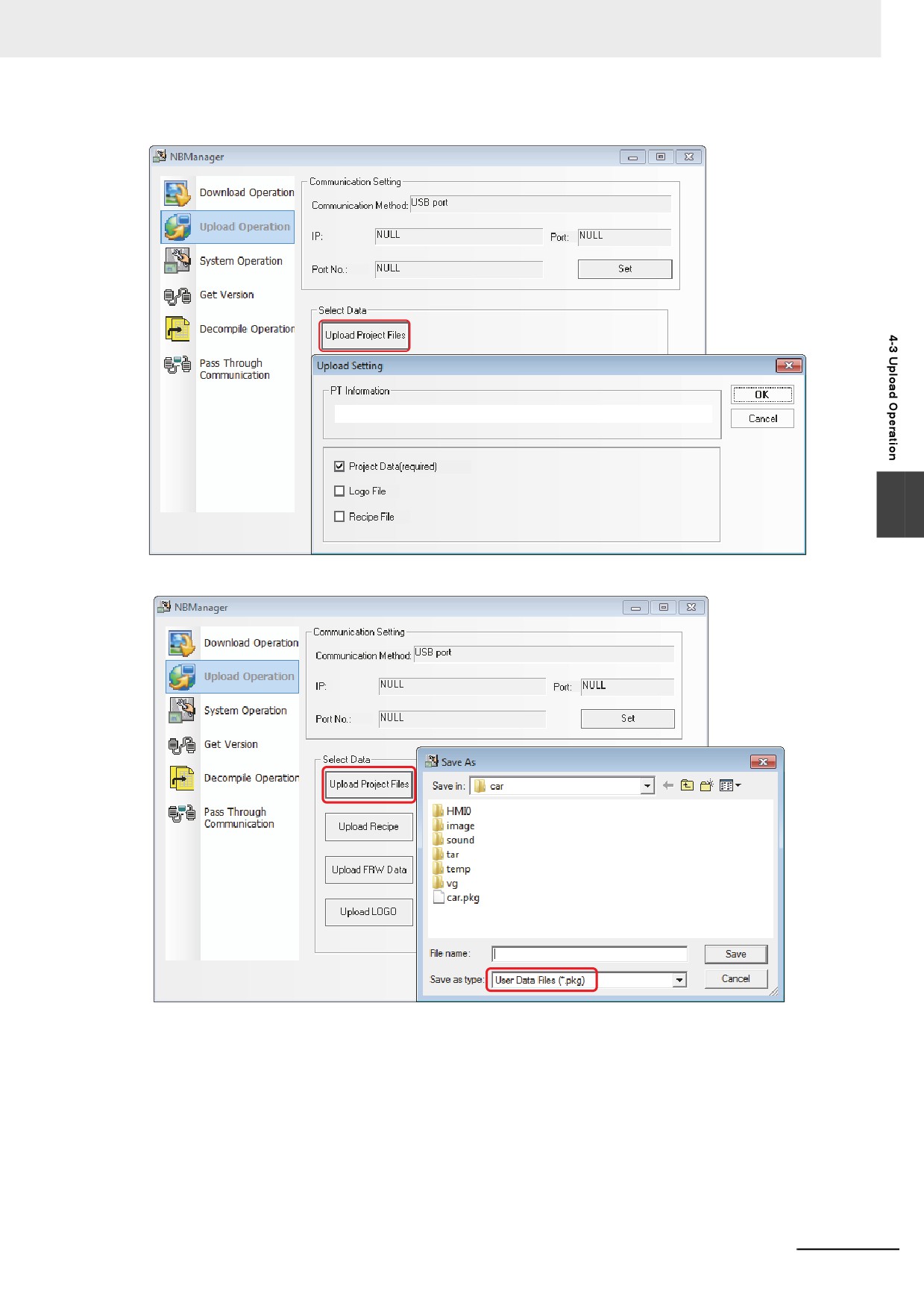
Upload Project Files:
Enter descriptions to [PT Information], if necessary.
Firstly check [Project Data (required)] and click the [OK] button to select the path for saving the data,
then click the [Save] button after inputting the file name.
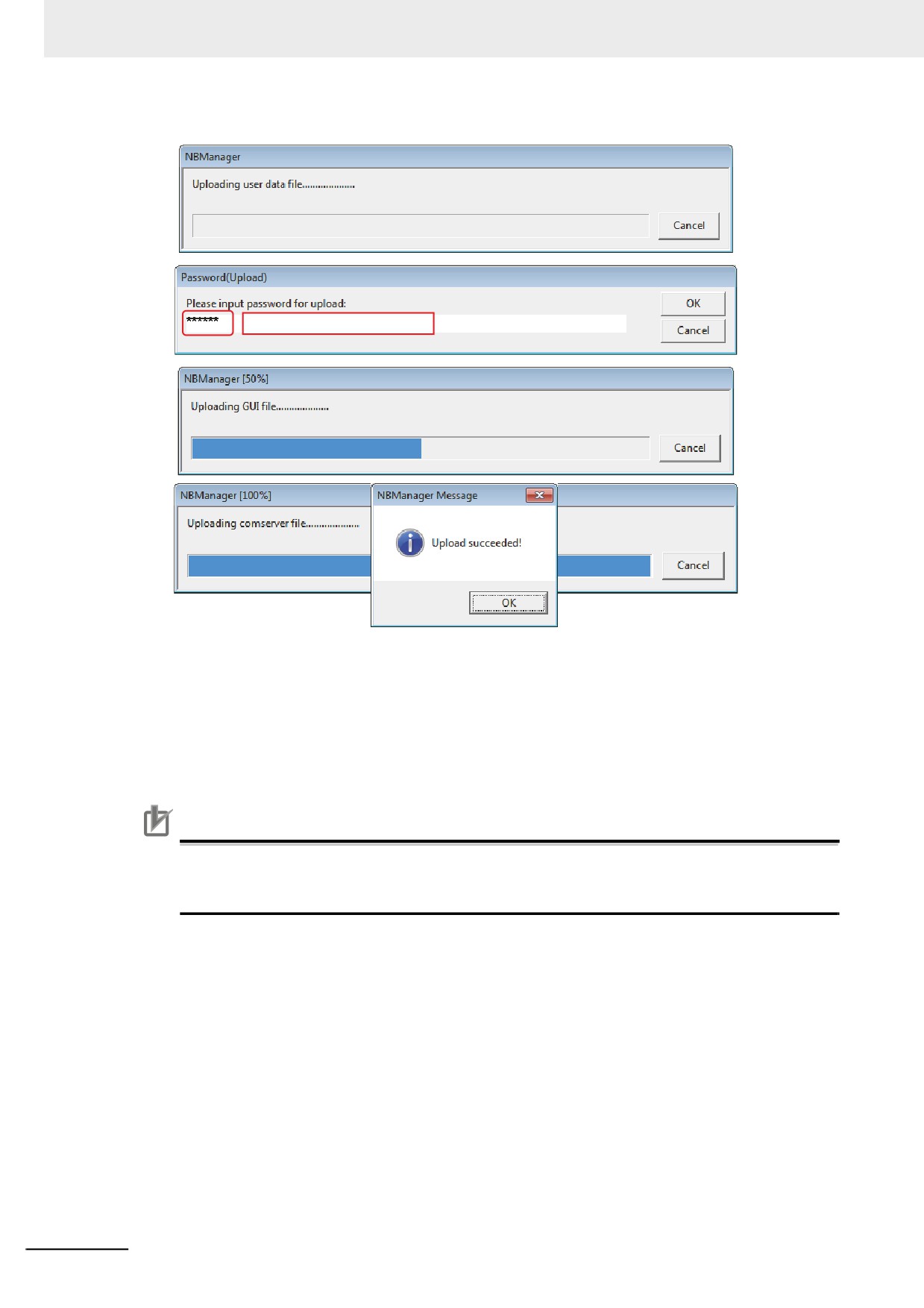
After the [Password(Upload)] pops up, input 888888 and press the OK button to perform the upload.
Note The default password for upload is 888888.
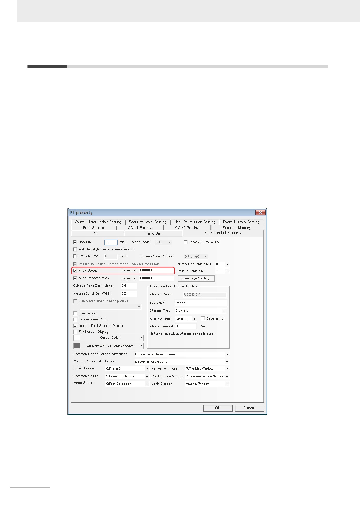
If you want to modify the upload password, please double-click the PT in Project Work Space and
modify [Password] corresponding to “Allow Upload” in [PT Extended Properties] tab.
4-12
4 Functions of NBManager
When Logo file and recipe file need to be uploaded, you can check “Logo File” and “Recipe File”.
4
4-13
4 Functions of NBManager
Default password is 888888
Select [Upload Recipe] and select the path to save the recipe, and then click the [Save] button after the
file name is input.
Select [Upload LOGO] and select the path to save the LOGO, then click the [Save] button after the file
name is input.
Select [Upload FRW] and select the path to save the FRW, and then click the [Save] button after the
File name is input.
The file name and the path saved during the upload can be selected by the user freely.
Precautions for Correct Use
Uploading the data that created with NB-Designer version 1.34 or earlier using NB-Designer ver-
sion 1.35 or later may fail. Upload the data with NB-Designer version 1.34 or earlier and decom-
pile it first. Then open it again in NB-Designer version 1.35 or later.
4-14
4 Functions of NBManager
4-4
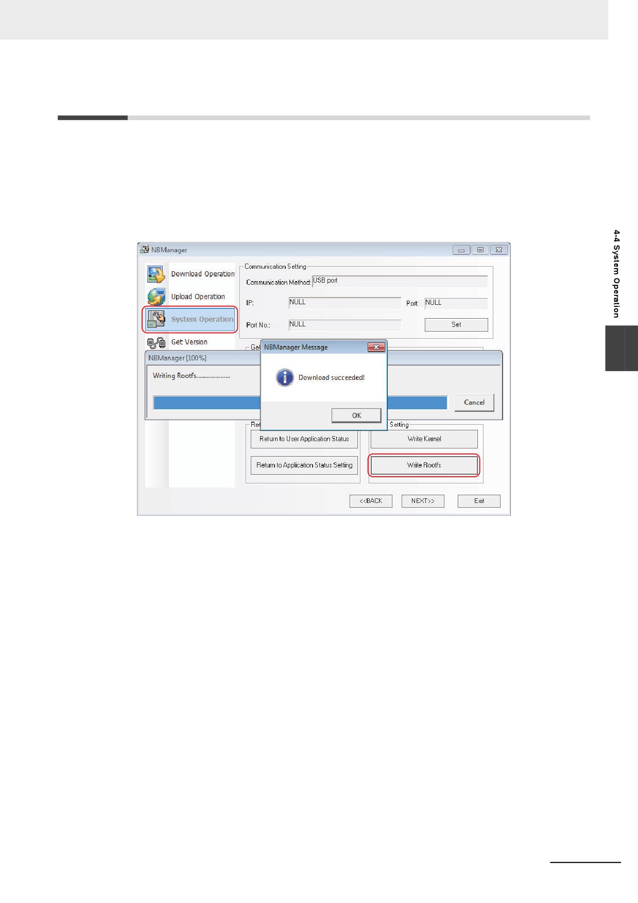
System Operation
Mode Settings:
When executing user projects: Specify the destination PT to the User Project Mode.
When executing system settings: Specify the destination PT to the System Setting Mode.
Operating Update:
Update Kernel and Rootfs. Specify the DIP switch located in the back of the NB unit to Downloader
Mode (SW1: ON, SW2: OFF) before the update and restart the NB unit.
4
Note After the updates of the Kernel and Rootfs, the NB unit settings will return to the factory settings and the
screen data will be removed. Note that point when you perform the operation.
4-15
4 Functions of NBManager
4-5
Get Version
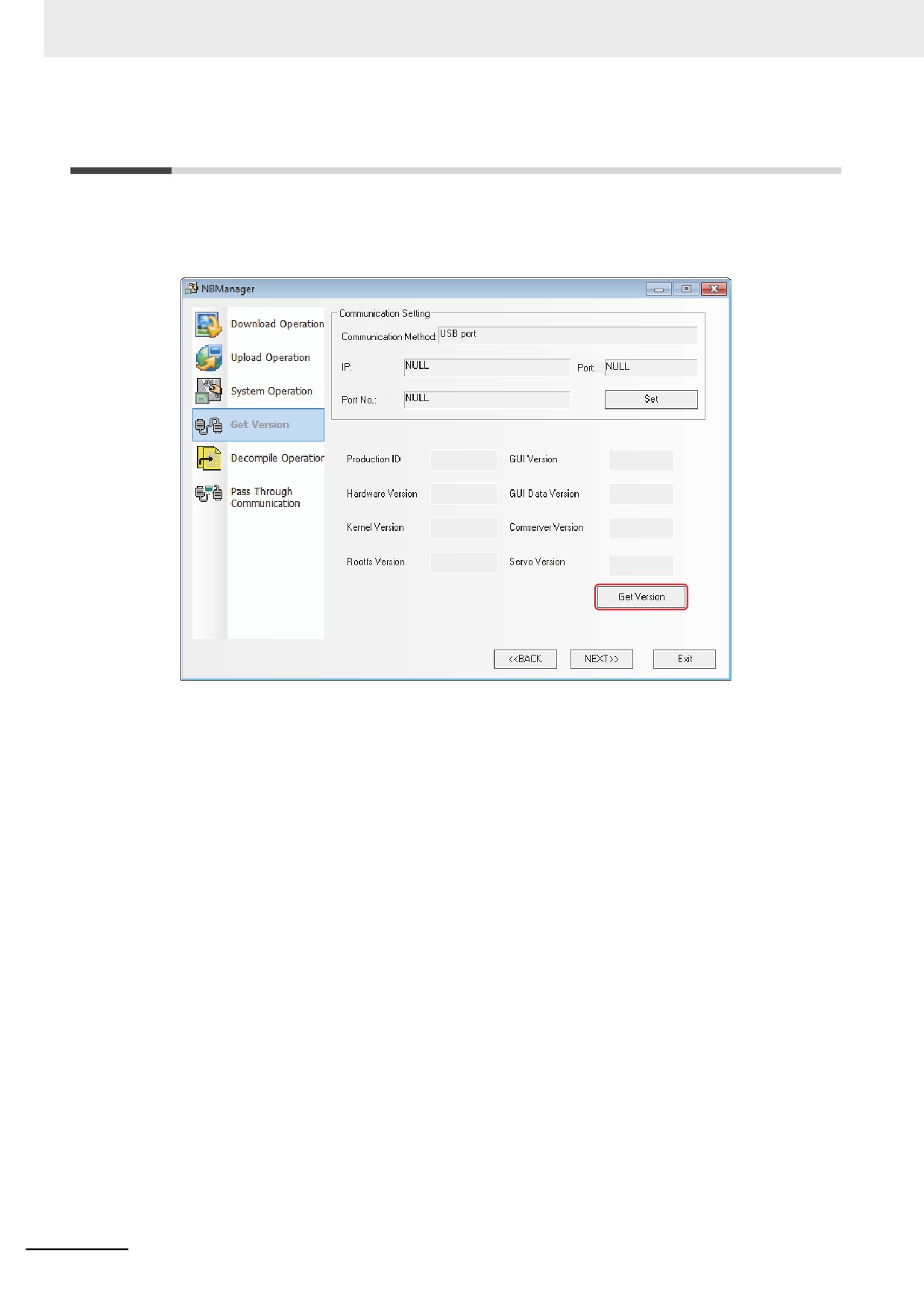
z Get Version:
Clicking the [Get Version] can obtain the Production ID of NB Unit, Hardware Version, Kernel Ver-
sion, Rootfs Version, GUI Version, GUI Data Version, Comserver Version and Servo Version.
4-16
4 Functions of NBManager
4-6
Decompile Operation
z Decompile Operation:
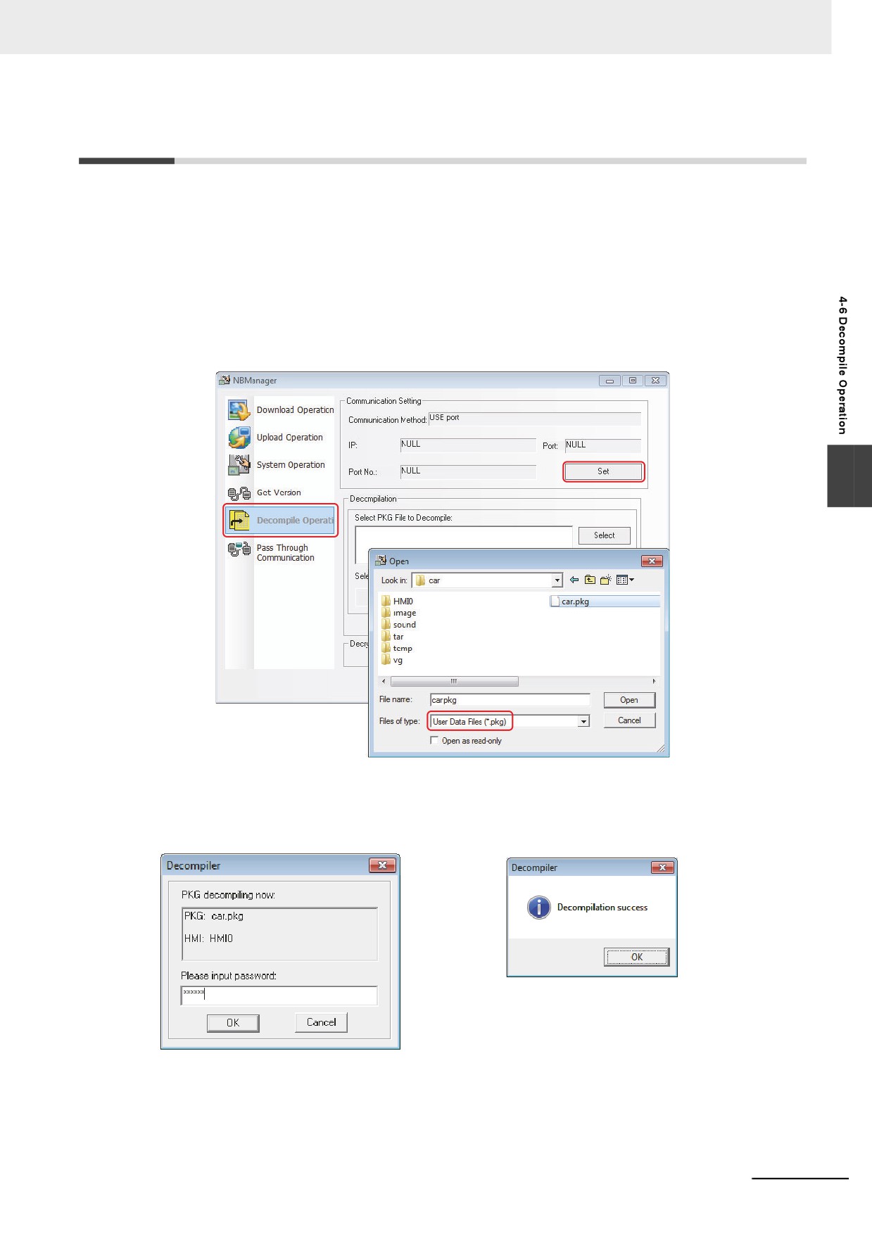
Convert PKG file to the format which can be handled with the NB-Designer.
Note When the multiple PTs are registered in a project, all the PKG files of PTs registered in the project are nec-
essary to be prepared.
1 Select .pkg files.
2 Set the folder of “Select Target Project Folder to Decompile”.
4
3 Click the [Decompile] button and input the decompile password, then click the OK button. When
the decomplie is completed, “Decompilation success!” dialog box will pop up.
The prerequisite for the decompile operation is “Allow Decompilation” is checked and the pass-
word is set in the [PT Extended Properties] tab during the project creation. The default decompi-
lation password is 888888.
4-17
4 Functions of NBManager
4-7
Pass Through Communication
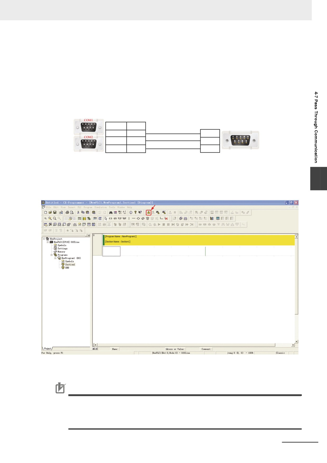
Pass Through Communication provided by NBManager allows the PLC programming software on PC
to connect the PLC directly via PT. In this case, PT functions just as the converter, so the user can
monitor or modify the PLC via PT, and the user can perform upload or download of PLC programs.
The only Communications available through the Pass Through Communications is the ones with Serial
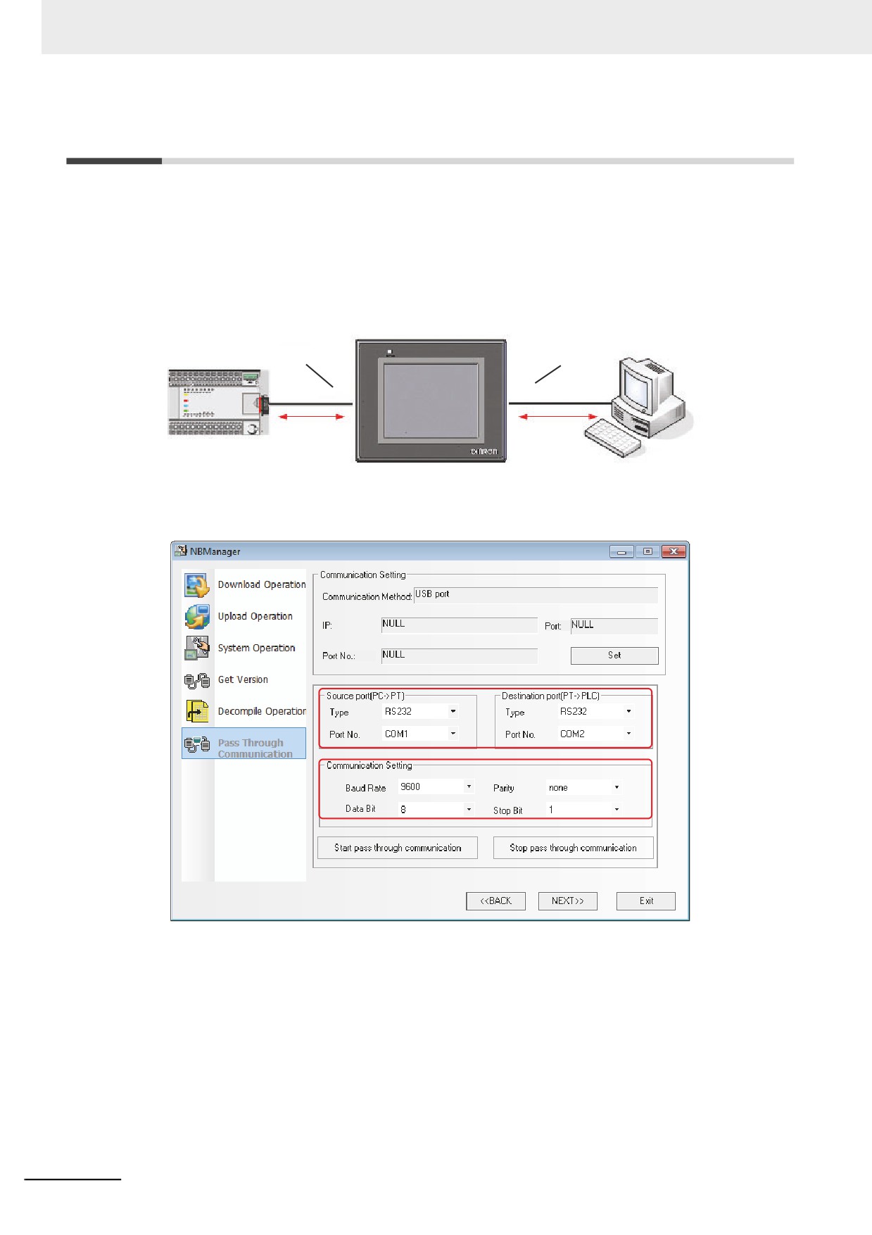
port. The connection is as shown below.
Caution It does not support the Pass Through Communication through other PLC than that manufactured by
OMRON.
Destination port
Source port
COM
COM
COM
PLC
PC
Please set the Source port and Destination port of the Pass Through Communications. Source port
refers to the serial port of PT for connecting PC, while the Destination port refers to the serial port of PT
for connecting the PLC.
Take the communication between OMRON CP1H and NB5Q as example, and the operation
procedures are as follows:
1 Open the NBManager and select Pass Through Communication.
2 Specify the Communications path to control the Pass Through Communications with the Com-
munications settings. Select [USB port] in this case. The Serial port cannot be used to control
the Pass Through Communications. USB port is used to control the start and end of the pass
through communication.
3 Set the Source port and Destination port, as shown above.
4-18
4 Functions of NBManager
4 The communication parameters are consistent with the settings of the Communications in
OMRON CP1H.
5 Connect the data transmission cable.
Connect the communication cable of OMRON CP1H to COM2 of PT, and connect the COM1of
PT and COM port of PC with the cable.
Note NB3Q-TW
B has only 1 COM port, so the pass through communication cannot be carried out.
Wiring of twisted cable:
PT connector
9pin D-SUB female
PC connector
COM 1
COM 2
9pin D-SUB (male)
3 RD
3 RD
3 TXD
2 SD
2 SD
2 RXD
9 SG
9 SG
5 GND
6 After “Start pass through communication” is clicked, PT will be in “Pass through mode”, and
“Pass through communication set successfully!” dialog box will pop up in NBManager.
4
7 Open CX-programmer for OMRON CP1H. Select “Online Operation”, then the PLC data can be
monitored or modified after the successful online.
8 Selecting “Stop pass through communication” will make “Pass through communication stopped
successfully!” dialog box pop up.
Precautions for Correct Use
• During the Communications with the Pass Through Communications, NB unit can be
accessed only within the system and the operations of the user project will be stopped.
• Besides the path of the Communications to communicate with PLC and others, the Communi-
cations path which controls the Pass Through Communications should be prepared.
4-19
4 Functions of NBManager
4-8
Web Interface Operation
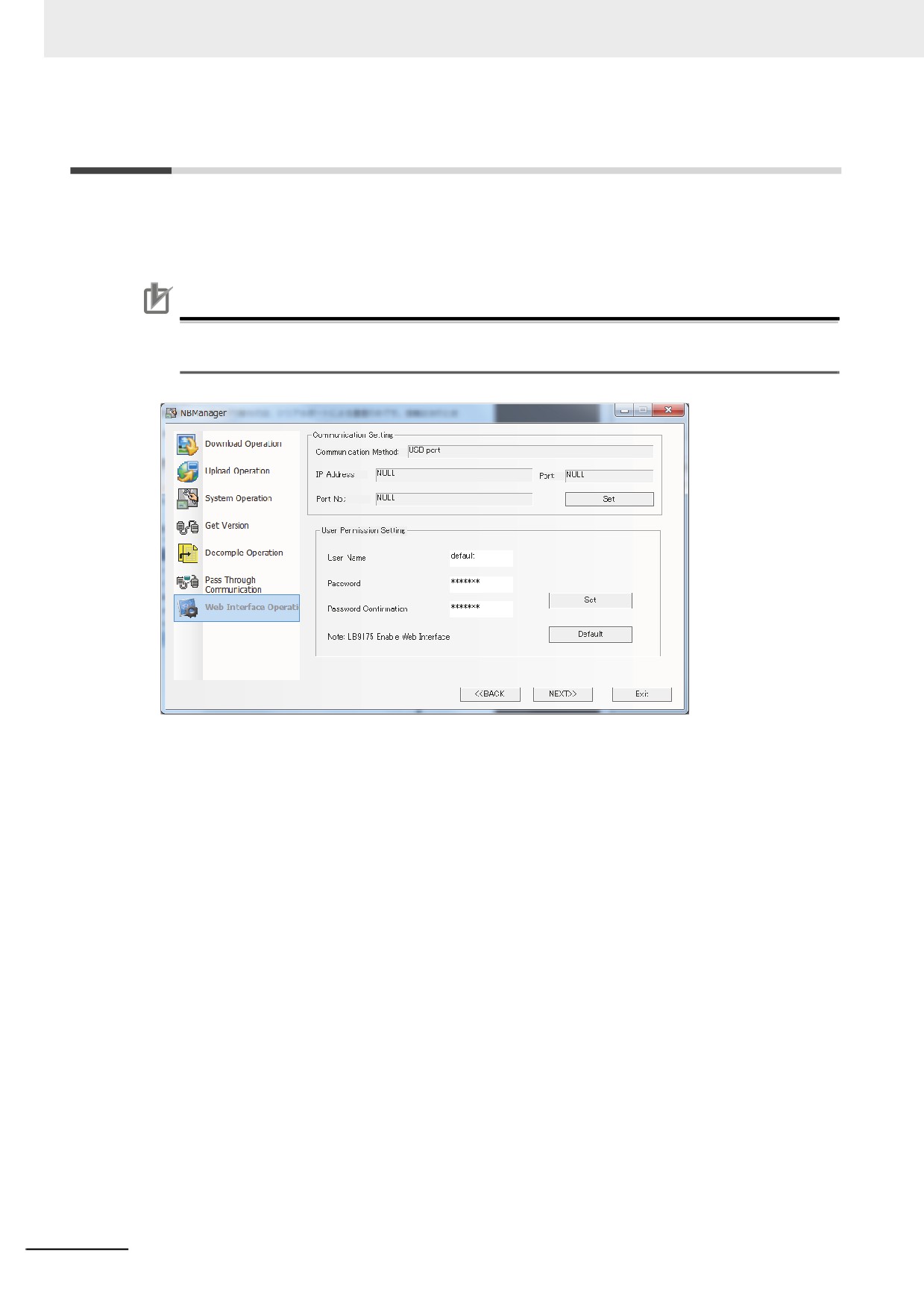
Set User Name and Password for using Web Interface. Refer to Web Interface (Page 8-1) for the
details of the Web interface.
Precautions for Correct Use
When you use Web interface, always modify User Name and Password into ones other than the
default settings in the respect of security.
1 Set User Name.
2 Set Password and Password Confirmation.
3 When you click [Set], User Name and Password will be transferred to the NB Unit.
Note 1
Available number of character available to set User Name and Password is 32 characters at max. Also the
available characters are restricted to single-byte alphanumeric and upper and lowercase are distin-
guished.
2
Clicking [Default] allows the User Name and Password to be returned to the default.
4-20
Maintenance and Abnormality
Handling
This section describes the maintenance and check to prevent the abnormality
occurrence and the handling of the abnormalities occurred in NB Unit.
5-1
Maintenance
5-2
5
5-2
Checking and Cleaning
5-4
5-3
Abnormality Handling
5-6
5-4
Unit Replacement Precautions
5-10
5-1
5 Maintenance and Abnormality Handling
5-1
Maintenance
Please perform the maintenance to ensure the NB Series always in the optimal status.
WARNING
Do not attempt to take the product apart and do not touch the product inside while the
power is being supplied. Otherwise it may result in electric shock.
Always ensure that the personnel in charge confirm that installation, inspection, and
maintenance were properly performed for the NB unit.
“Personnel in charge” refers to individuals qualified and responsible for ensuring
safety during machine design, installation, operation, maintenance, and disposal.
Ensure that installation and post-installation checks are performed by personnel in
charge who possess a thorough understanding of the machinery to be installed.
Do not use the input functions of the touch switch, etc. of the NB Unit, in applications
that involve human life, in applications that may result in serious injury, or for
emergency stop switches.
Do not attempt to disassemble, repair, or modify the NB Unit. Otherwise it may impair
the safety functions.
Never press at two or more points on the touch panel of the NB Unit at a time.
Otherwise, it may activate a switch somewhere between the two points.
5-2
5 Maintenance and Abnormality Handling
z Backup of application
When the unit needs to be repaired due to the occurrence of some faults or to be replaced by the
substitute, be sure to make backup of the applications and keep it in a safe location.
z Spare part of Unit
It is recommended to prepare the spare part of NB Unit in advance in order to repair the system
when the faults occurred in NB Unit or the screen is not clear due to the backlight life expires.
z Replace of battery
The lithium battery is used for the backup of the non-screen data such as calendar data, clock data
etc.
The life of the battery is approximate 5 years at 25 °C (1 year = 365 days ×12 hours /day). If the
battery is used at high temperature, its life will be reduced. According to the ambient environment,
after taking back-up of the data, request for the repair.
5
5-3
5 Maintenance and Abnormality Handling
5-2
Checking and Cleaning
Please clean and check the NB Series periodically to ensure the NB Series always in the optimal
status.
z Cleaning method
If the display part is dirty, then the screen will hard to see. Please perform cleaning periodically
according to the following points:
• During the daily cleaning, please use the dry soft cloth. But if use the dry soft cloth to clean
forcefully when it is too dirty, the front panel may be damaged. In this case, use the wet cloth to
clean it in advance.
• When the dirt cannot be cleaned by dry cleaning, please dip the cloth into the diluted neutral
washing agents (concentration of 2%) completely first, and then perform cleaning after the wet
cloth is wringed out.
• Waste, ethylene products or tape sticking to the Unit for a long period will generate dirt. If there is
dirt sticking to the Unit, please remove it during the cleaning.
Precautions for Safe Use
Do not use benzene, paint thinner, or other volatile solvents, and do not use chemically treated
cloths.
z Checking method
Please perform checking once every 6 months to 1 year. But the frequent checking should be
necessary when the Unit is used in the extreme environments such as the environment with high
temperature, high humidity or more dust etc.
z Checking items
Please check the following items for the criterion. If the item doesn’t conform to the criterion, please
improve the surrounding environment, retighten the screw etc. to make it conform to the criterion.
Checking Items
Checking Contents
Criterion
Checking Method
Supply voltage
Voltage fluctuation at
Allowable voltage
Multimeter
power terminal
fluctuation range
(DC24V, -15% to +15%)
Surrounding environment
Ambient temperature
0°~50°C
Thermometer
state
(temperature inside
operation panel)
Ambient humidity
10%~90% RH(without
Hygrometer
(humidity inside operation
condensation)
panel)
Dirt
Without dirt
Visual check
Oil mist sticking
No oil penetrating into the
Visual check
space between the front
panel and Unit box
5-4
5 Maintenance and Abnormality Handling
Checking Items
Checking Contents
Criterion
Checking Method
Installation state
Looseness of fixing metal
Specified torque
Phillips screwdrivers
pieces etc.
Connection state of
Inserted fully and without
Phillips screwdrivers
connector for the cable
looseness.
Looseness of screw for
Without looseness
Phillips screwdrivers
external wiring
State of external
Without abnormality such
Visual check + multimeter
connection cable
as disconnection etc.
Object with expected life
Backlight brightness
With enough brightness
Visual check
Backlight life: approx.
50,000 hours (Typ) at
room temperature (25 °C)
with 40% brightness.
Battery
5 years (at 25 °C)
NB local time
Precautions for Safe Use
• The back light or rubber packing of NB unit cannot be replaced.
• Deterioration over time can cause the tough points to move. If the Calibrate the touch panel
periodically.
• Water resistance will be lost if the front sheet is torn or is peeling off. Do not use the Unit, if the
5
front sheet is torn or is peeling off.
• Dispose of the Units and batteries according to local ordinances as they apply.
• Periodically check the installation conditions in applications where the PT is subject to contact
with oil or water.
• The rubber packing will deteriorate, shrink, or harden depending on the operating environ-
ment. Inspect the rubber packing periodically.
• In order to replace the battery, the NB units are also necessary to be replaced. Although it is
restricted to NB10W-01B, the battery replacement is available to be dealt as a repair.
5-5
5 Maintenance and Abnormality Handling
5-3
Abnormality Handling
This section describes the handling methods for the abnormalities.
z During abnormality occurrence
When the abnormality occurred during the operation of PT unit, the following information will prompt.
WARNING
Do not attempt to disassemble, repair, or modify the NB Unit. Otherwise it may impair
the safety functions.
Precautions for Safe Use
Confirm the safety of the system before turning ON or OFF the power supply, or pressing the
reset button.
Information
Descriptions
PLC no response: cc-pp-d
PLC No Response: the 3 group of numbers following PLC No Response represent
the PT No., PLC Station No. and Serial Port No. respectively.
PLC response error
PLC response error: PLC responses one piece of unexpected information which
may caused by the read or write command. Please check if the device functions
well.
Macro Code Error: xxxx
Programming problems, endless loop or execution timeout exist in Macro. Please
(Macro No.)
check the Marco. The number in the later position is the Macro No.
System error
It is system error which means the error occurs inside the PT.
5-6

5 Maintenance and Abnormality Handling
z
Solutions for “PLC no response” and “PLC response error”
PLC no response
Yes
Check whether the type and settings
NO
Check if the PLC Type used currently and the
of the PLC are correct or not.
one for the PLC on the project are correct.
Yes
Check whether the cable is
NO
Refer to [Appendix-4 Fabrication of the Connec-
wired correctly or not.
tion Cable] in NB series Setup Manual.
Yes
Check whether the baud rate, parity bit, data bit,
Check whether the communi-
NO
stop bit are correct or not, the communication type
cation setting is correct or not.
is RS232 or RS485?
Refer to [Appendix-4 Fabrication of the Connection
Cable] in NB series Setup Manual.
Yes
Check whether PLC station
NO
Refer to [Appendix-4 Fabrication of the Connec-
no. is correct or not.
tion Cable] in NB series Setup Manual.
Yes
Check whether the PLC area
NO
Check the content of the variable table.
and range are correct or not.
Yes
Check whether the PLC address
NO
Refer to the relevant PLC document.
supports the write operation.
Yes
Please contact with
OMRON service center.
5
PLC response error
Yes
Check whether the type and settings
NO
Check if the PLC Type used currently and the
of the PLC are correct or not.
one for the PLC on the project are correct.
Yes
Check whether the PLC area
NO
Check the content of the Variable Table.
and range are correct or not.
Yes
Check whether the PLC address
NO
Refer to the relevant PLC document.
supports the write operation.
Check the arrangement of 9-pin
RS-232C female socket port.
z
When compile error occurs
In the Output Window, you can see the error number and error reason such as:
Address error for Parts or over-limit.
Using too many screens and components may cause a compile error. The number of screens
should be approximately 2,000 or less, and the number of components should be 15,000 or less in
the entire project.
Operations related to files cannot be executed via networks.
Do not use the system locale-dependent characters for the project file name, graphics library file
name, and folder name.
5-7
5 Maintenance and Abnormality Handling
z When operations become slow or when a periodical process cannot be
executed as specified
Check the available memory space on the LW9136 system memory, and secure the adequate
memory. (LW9136 shows a reference value for available memory space.)
The periodically executed processes such as alarm detection, data logging, timer, or macro may
have a longer execution interval than specified or not be executed, depending on the loads caused
by screen display or communication, or the overlapping processes. Check the actual operation to
adjust the load of the process.
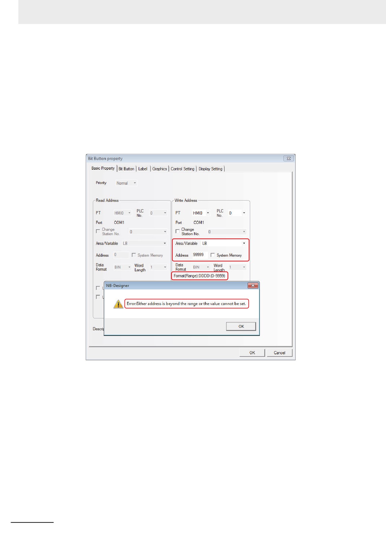
For some cases, NB-Designer will provide the information similar to “Either address is beyond the
range or the value cannot be set.” as shown below during the designing period.
For the settings of PLC address, refer to 3-5-4 Read/Write Address for PLC (Page 3-59) and for
information of PLC address, refer to PLC manual.
5-8
5 Maintenance and Abnormality Handling
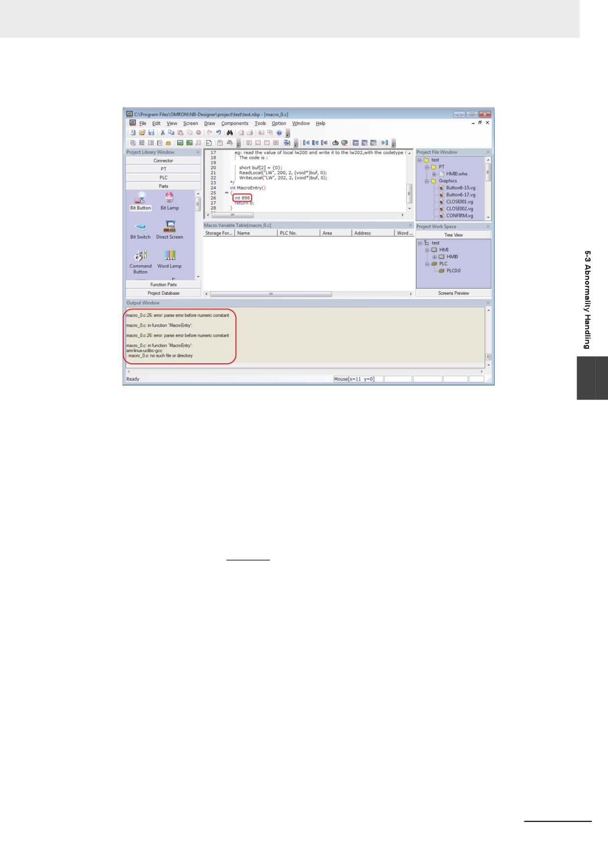
Grammatical errors as C language are checked during compilation in Macro and if any problem
occurs, it will be displayed.
5
For the Macro, refer to 3-9 Macro Function (Page 3-265).
z Some parts on the screen are not updated
Communications traffic is too much to update all the data. Reduce the number of the parts to update
to the level of proper data traffic.
z Data transmission component cannot transfer all the data
Traffic is too high to transfer all the data. Alter the time-out setting with LW9536/9537. For the time-
out setting, refer to the expression below:
X
Time-out Period
(T) = (
+1) × N sec.
M × 16
X: Total amount of transferred data (unit: word/bit)
M:The number that is defined as the maximum size of word/bit block package in the communication
settings of NB-Designer.
N:The value that is set in LW9536 (write) or LW9537 (read).
z Data upload is failed
Uploading the data that created with NB-Designer version 1.34 or earlier using NB-Designer version
1.35 or later may fail. If you fail in data upload, try again with NB-Designer version 1.34 or earlier.
5-9
5 Maintenance and Abnormality Handling
5-4
Unit Replacement Precautions
When the Unit should be replaced for the defectiveness found during the checking, please pay
attentions to the following points:
• Perform backup of the screen data of NB Unit in advance.
• The screen data may be deleted when the Unit is repaired by OMORN.
• Be sure to turn OFF the power supply before the replacement.
• After the replacement, please confirm whether the abnormality still exists or not.
• When the defect device is returned for repair, please attach the paper with the detailed description of
the problem to the Unit, and contact the supplier printed on the back cover.
5-10
Functions Related to External
Memory
This section describes the functions related to external memory.
6-1
Components Related to External Memory
6-2
6-1-1
Function Key
6-2
6-1-2
Event, Event History Display and Event Display
6-5
6-1-3
Data History, Data Log and XY Graph
6-7
6-1-4
Operation Log
6-8
6-1-5
Recipe Data
6-11
6
6-1-6
CSV Import / Export
6-12
6-1-7
PLC Control
6-13
6-1-8
File List
6-14
6-1-9
FTP Server
6-15
6-1
6 Functions Related to External Memory
6-1
Components Related to External
Memory
6-1-1
Function Key
Save Screenshot to external memory
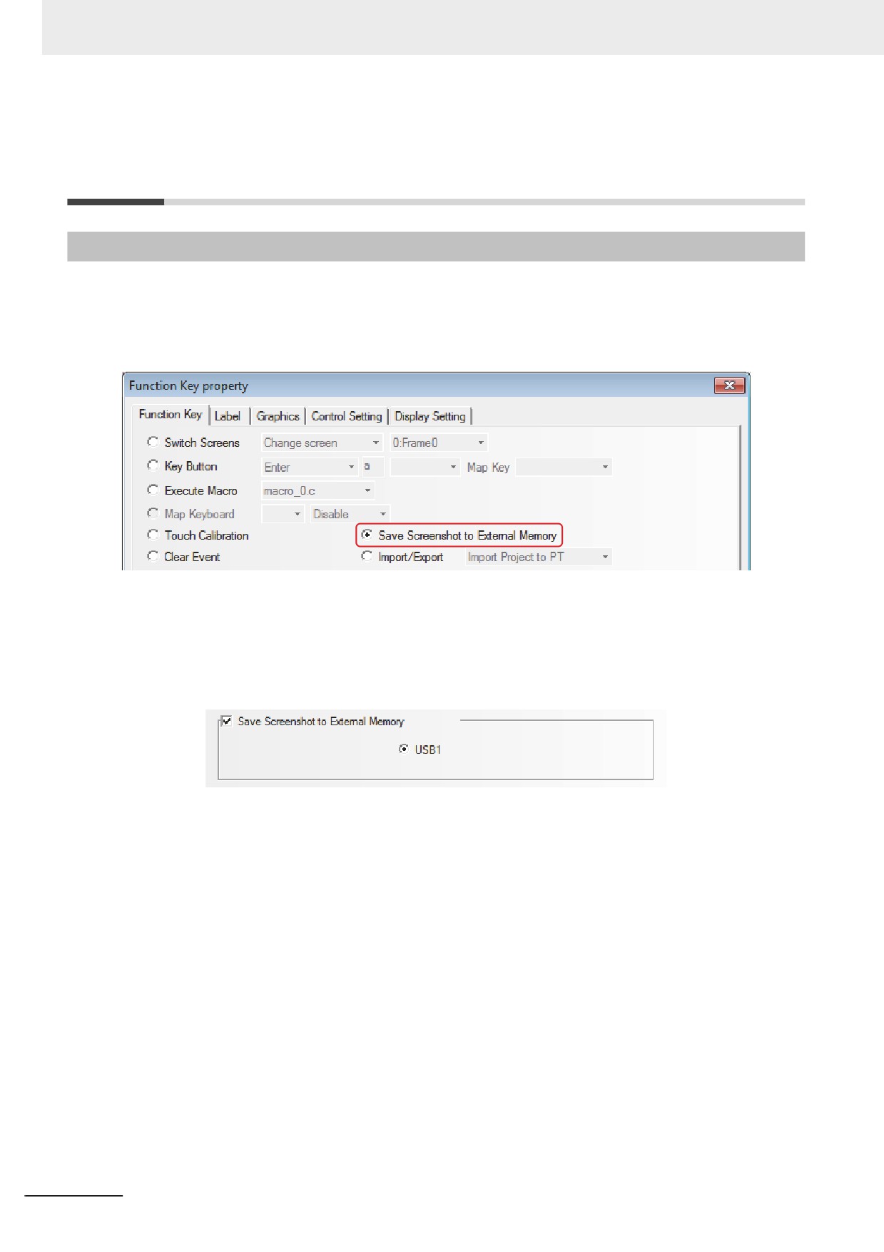
When the component is touched, the content of the current screen will be stored into the external
memory in the form of “bmp picture”. Using the this function allows the PT screen stored as the
graphics.
Note 1
“Save Screenshot to Extended Memory” is only applicable to the PT with USB HOST.
2
Function of “Save Screenshot to Extended Memory” supports the offline test, indirect online test and direct
online test. All the screenshot pictures got by this test method are stored in the “\disk\usb1\scr” file under
the installation folder of NB-Designer software.
To save the screenshot to the external memory, it needs to make settings in the [PT] tab in [PT
Property] dialog box.
The “.rmp” pictures stored in the external memory is named in storage time form (i.e. “yyyy-mm-dd,
hh:mm:ss:ms) by default, such as “2010-09-01, 10:12:50:203.bmp”. But the picture name can be
customized by the user through the system memory LW9470 to control the prefix text string of the
graphics file. For example: if the text contents of 16 words from LW9470 to LW9485 are “Version No. -
No.20100001-”, then the “bmp” file will be stored with the name of “Version No. -No.20100001-2010-
09-01, 10:15:28:421.bmp”.
Note After the “Save Screenshot to Extended Memory” operation is performed for about 1 minute, the external
memory can be removed to ensure the successful storage of the screenshot.
6-2
6 Functions Related to External Memory
Import/Export Function
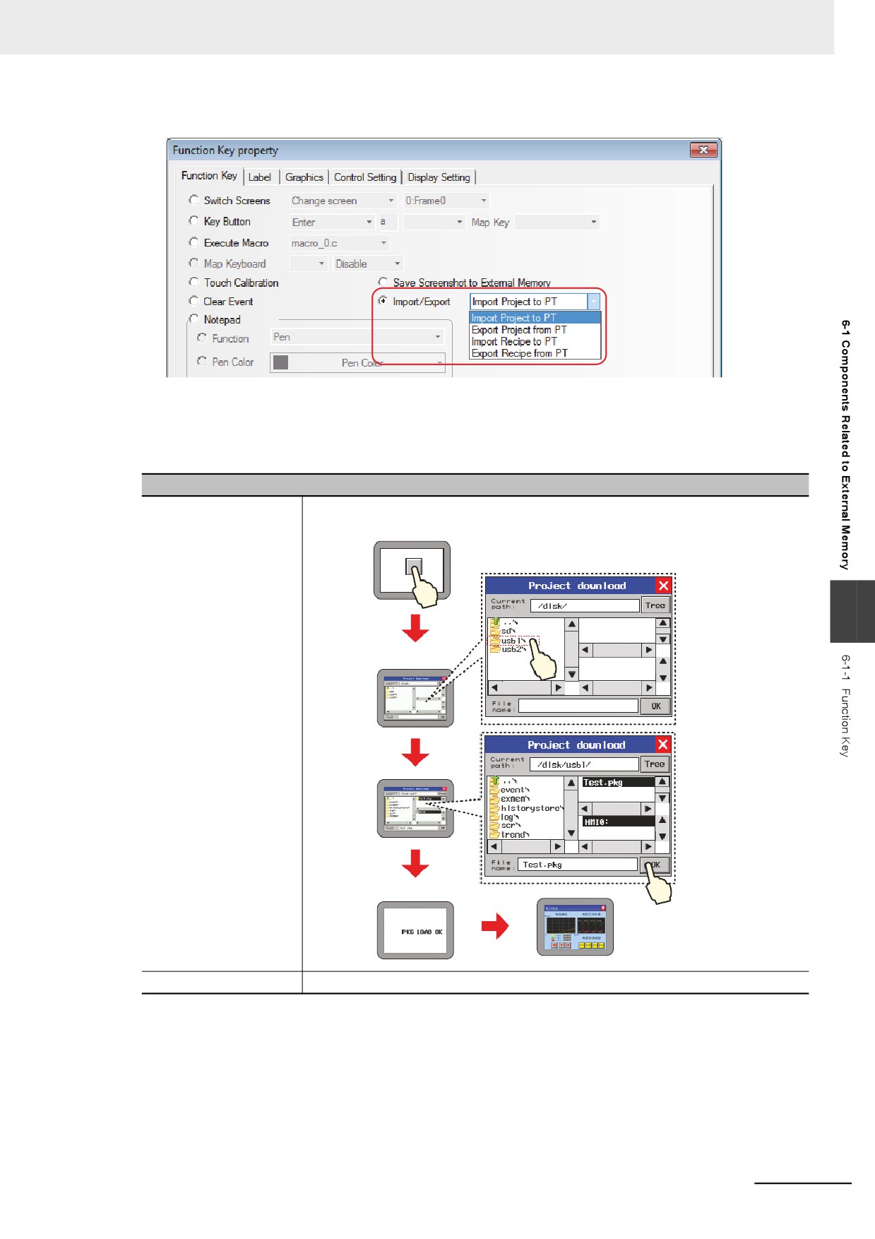
When this function is selected, touching the Function Key can realize the import or export of project
data and recipe data. This function needs to be used in combination with File List component and it is
only applicable to the PT with USB Host.
Descriptions of Import/Export Function
Import Project To PT
Imports the project (.pkg) from the external memory into the PT. After the project is
imported, the system will restart and the imported project will be operated.
6
Pop up Frame 5
PKG LOAD OK
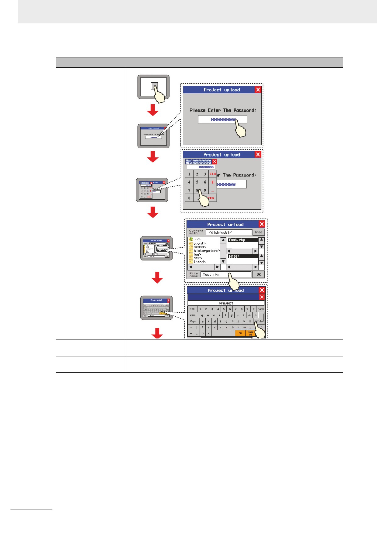
Export Project From PT
Exports the project (.pkg) from the PT into the external memory.
6-3
6 Functions Related to External Memory
Descriptions of Import/Export Function
Pop up Frame 6
Input upload
password
Pop up Frame 5 and
select save path
Input file name
Import Recipe To PT
Imports the recipe file (.rcp) from the external memory into the PT. For the operation
procedures, refer to [Import Project To PT].
Export Recipe From PT
Exports the recipe file (.rcp) from the PT into the external memory. For the operation
procedures, refer to [Export Project From PT].
6-4
6 Functions Related to External Memory
6-1-2
Event, Event History Display and Event Display
z Saving Event, Event History Display and Event Display into the external
memory:
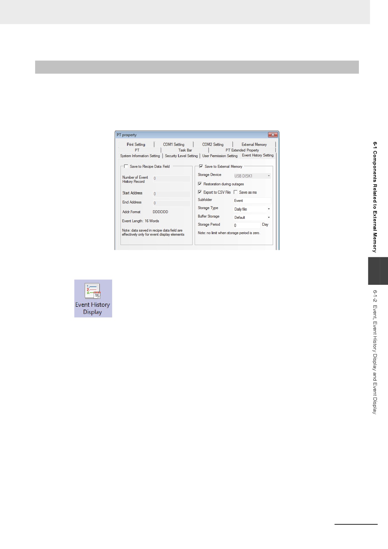
The Event, Event History Display and Event Display can be stored in the external memory by check-
ing the [Save to External Memory] option in the [Event History Setting] tab in the [PT Property] dia-
log box, as shown below:
z Event History Display
6
The Event History Display component is used to search and display the event history
information, which is logged in “Event Setting” database and whose state meets the current
triggering conditions, in the table form.
Note 1
The [Read Address] for the Event History Display is the memory address used for searching the histor-
ical event records. The default Word Length is 2.
2
The Event History Display component only supports the PT with USB HOST.
3
If the Event History Display component is to be used, it needs to check the [Save to External Memory]
option in the [Event History Setting] tab in the [PT Property] dialog box and set the path for storing the
historical event information files.
6-5
6 Functions Related to External Memory
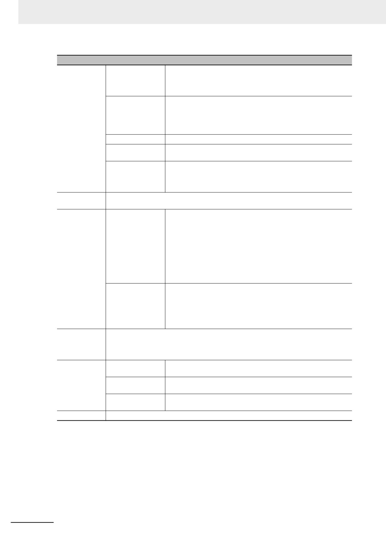
Descriptions of Table Display Properties
Display Item
Time
Checking it means the event occurred time, checked time and
canceled time will be displayed and the time format can be selected
There are 3 formats available, and HH, MM, SS and MS refer to the
hour, minute, second and millisecond respectively.
Date
Checking it means the event occurred date, checked date and
canceled date will be displayed and the date format can be selected
among three formats such as DD*MM*YY, MM*DD*YY, and
YY*MM*DD, and YY, MM and DD refer to the year, month and date
respectively.
Date Separator
Three characters of delimiter(/,-,.) are available. i.e. 11/06/24.
Sequence Number
Checking it the sequence number of each event information will be
displayed.
Ascending
When it is checked, the event information will be displayed in the
ascending order, i.e. the latest event will be displayed on the bottom.
When it is not checked, the event information will be displayed in the
descending order, i.e. the latest event will be displayed on the top.
Background
Sets the Background Color, Title Bar Background Color, Frame Color and Frame Width for the
Color
Event History Display component table.
Event History
Query by File Name
When it is checked, the value of specified memory being 0 means to
Query
call out today’s or the latest event history information, and the value of
specified memory being 1 means to call out the event history
information stored on the previous day and so on. [For example] With
two event history information files 20110621.csv and 20110624.csv
stored in the external memory, when the value of specified memory is
0, the event history information stored on June 24th, 2011 can be
called out, while the event history information stored on June 21th,
2011 can be called out and displayed when the value of specified
memory is 1.
Query by Date
When it is checked, the date will be input into the specified memory
and the event history information corresponding to the date will be
called out. The date format is yyyymmdd (Where, yyyy, mm and dd
refer to the year, month and date respectively.) [For example] Inputting
20110624 into the specified memory can call out and display the event
history information saved on June 24th, 2011.
Border Setting
Border Color, Style and Width for each row or each column and the Row Spacing and Column
Spacing with the unit of pixel point. Checking “Horizontal Line” means the separator will be
displayed horizontally, and checking “Vertical Line” means the separator will be displayed
vertically.
Status display
Occurring
Display the information indicates that the event is occurring in the
status column. Although it is set to “0” by default, it can be modified.
Checked
Display the information indicates that the event is checked in the status
column. Although it is set to “1” by default, it can be modified.
Canceled
Display the information indicates that the event is canceled in the
status column. Although it is set to “2” by default, it can be modified.
Title Bar Setting
Sets the Name and Font displayed in Title Bar of the table.
6-6
6 Functions Related to External Memory
6-1-3
Data History, Data Log and XY Graph
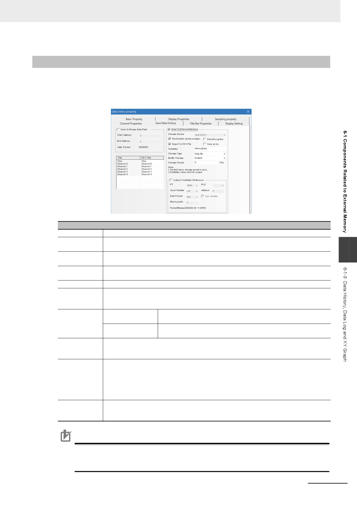
z Saving the related information into the external memory:
When the sampling data is being saved into the external memory, if you want to remove the external
memory from the PT, the special system memory LB9154 (USB1) must be turned OFF before
removal. If the external memory is removed without the procedure, the data will be corrupted lost.
Descriptions of Save Historical Data
Storage Device
USB 1
Restoration
When the NB units restarts because of the power interruption, checking in this option allows
during outages
resetting the event information to the previous status of the power interruption.
6
Export to CSV
Export the data information in CSV format to the external memory. The path for storing this
File
CSV file is “/trend/subfolder name/file name”.
CSV Title
When exporting the data to a csv file, you can give titles by each channel. If you change the
number of channels, titles become default ones.
Save as ms
Makes the data sampling time accurate to the millisecond and records it into the CSV file.
Subfolder
Sets the subfolder name of CSV file saved to the external memory. The users can change the
default subfolder name of Data History component by themselves to “History Data”, that of
Data Log component to “History Trend” and that of XY Graph to “XY_CHART”.
Storage Type
Daily File
Stores the sampling data by day and records them into the CSV file
named in “yyyy mmdd” form.
Single File
Stores the sampling data by the number of records and records them
into the CSV file with the name of “Subfolder Name”.
Buffer Storage
Provides a kind of buffer storage mechanism. When the data written into the external memory
amounts to the set size of the buffers, the writing is only performed once. “Default” means no
buffering, i.e. the writing operation will immediately be performed once the data is generated.
Storage Period
Sets the upper limit for the storage amount of data history with the unit of “Day” for Daily File and “Record”
for Single File. When the [Daily File] is selected, the file will be named in “yyyy mmdd” form and the
Storage Period is the upper limits of the number of CSV files in this path; if the Storage Period is exceeded,
the oldest file will be deleted. If the [Single File] is selected, the file will be named in “Subfolder Name” form,
the Storage Period is the upper limit of the records archived in the file; if the archived records are reached
to the Storage Period, the storage will not be continued. (yyyymmdd refers to the execution date.)
Indirect
Sets the name of subfolder read from the specified memory with the word length up to 16.
Subfolder
Reference
Precautions for Correct Use
When saved to a CSV file, a title may differ depending on the version of NB-Designer for compi-
lation. NB-Designer with version 1.49 and earlier does not have the function to change a title and
the title is output in the default text to a CSV file.
6-7
6 Functions Related to External Memory
6-1-4
Operation Log
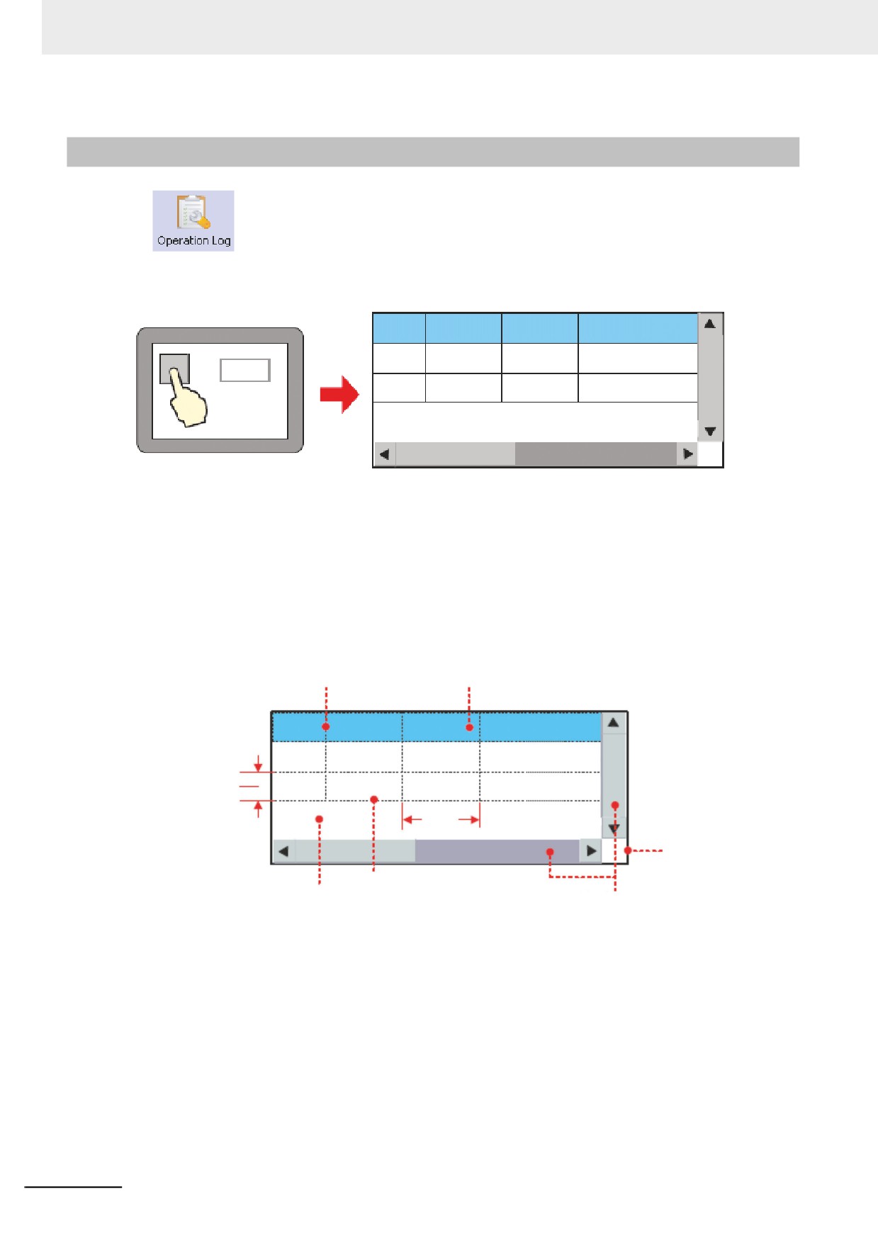
The Operation Log component can be used to record or display the operations made
by the users to the PT in the table form. The operation log will be stored into the external memory in
CSV format.
No. Date Time
Log
0
11/06/24
11:23:20
Parameter Corr
123
1
11/06/24
11:22:45
Start Running
Note 1
The [Read Address] for the Operation Log component is the memory address used for searching the
operation logs. The default Word Length is 2.
2
The Operation Log component can display the operated results of Bit Button, Number Input and Text
Input components etc.
3
The Operation Log component is only applicable to the PT with USB HOST.
z Descriptions of Table Properties:
Vertical Line
Title Bar
No.
Date
Time
Log
0
11/06/24
11:23:20
Parameter Corr
Row Spacing
1
11/06/24
11:22:45
Start Running
Column
Space
Frame
Horizontal Line
Background
System Scroll Bar*
Note When the information in vertical and/or horizontal direction contained in the Operation Log component can
not be displayed completely, the system will automatically display the scroll bar for the user to conveniently
view the operational records by scrolling up and down.
The System Scroll Bar Width can be set to the value ranging from 20 to 120 (pixel) in the [PT
Extended Properties] tab in [PT Property] dialog box.
6-8
6 Functions Related to External Memory
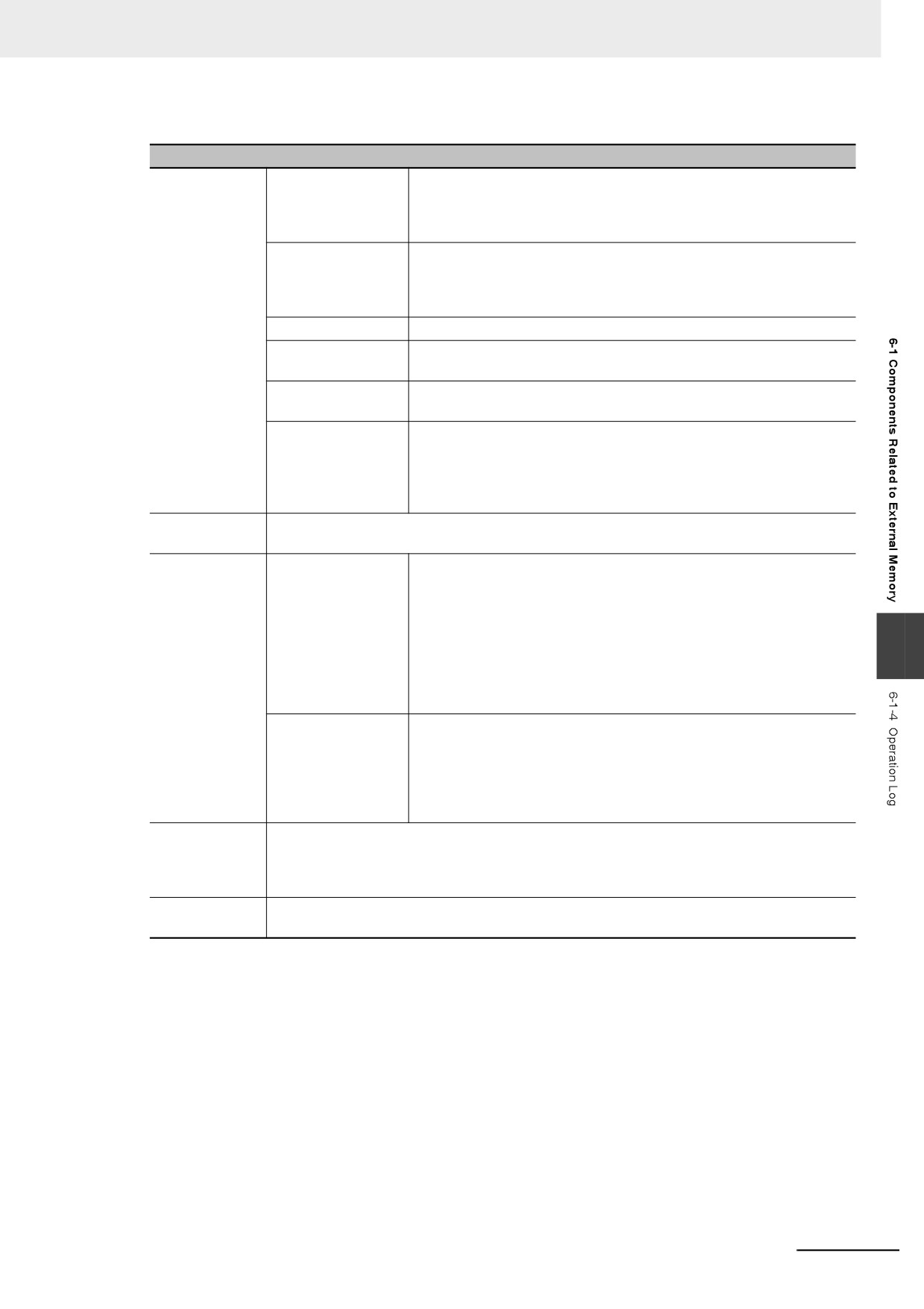
Descriptions of Table Display Properties
Display Item
Time
Checking it means the operation time will be displayed and the time
format can be selected. There are 3 time formats available (such as
HH:MM:SS, HH:MM, and HH:MM:SS:MS), and HH, MM, SS and MS
refer to the hour, minute, second and millisecond respectively.
Date
Checking it means the operation date will be displayed and the date
format can be selected. There are 3 time formats available (such as
DD*MM*YY, MM*DD*YY, YY*MM*DD), and YY, MM and DD refer to
the year, month and date respectively.
Date Separator
Three characters of delimiter(/,-,.) are available. i.e. 11/06/24.
Sequence Number
Checking it means the sequence number of each operation record will
be displayed.
User Name
Checking it means to the information on the user performing the
current operation will be displayed.
Ascending
When it is checked, the operation logs will be displayed in the
ascending order, i.e. the latest operation log will be displayed on the
bottom. When it is not checked, the operation logs will be displayed in
the descending order, i.e. the latest operation log will be displayed on
the top.
Background
Sets the Background Color, Title Bar Background Color, Frame Color and Frame Width for the
Color
Operation Log table.
Operation Log
Query by File Name
When it is checked, the value of specified memory being 0 means to
Query
call out today’s or the latest operational records, and the value of
specified memory being 1 means to call out the operational records
made on the previous day and so on. [For example] With two operation
log files 20110621.csv and 20110624.csv stored in the external
6
memory, when the value of specified memory is 0, the operation logs
saved on June 24th, 2011 can be called out, while the operational
records saved on June 21th, 2011 can be called out and displayed
when the value of specified memory is 1.
Query by Date
When it is checked, the date will be input into the specified memory
and the operation logs corresponding to this date will be called out.
The date format is yyyymmdd, where yyyy, mm and dd refer to year,
month and date respectively. [For example] Inputting 20110624 into
the specified memory can call out and display the operation logs saved
on June 24th, 2011.
Border Setting
Sets the Border Color, Style and Width for each row or each column and the Row Spacing
and Column Spacing with the unit of pixel. Checking “Horizontal Line” means the separator
will be displayed horizontally, and checking “Vertical Line” means the separator will be
displayed vertically.
Title Bar
Sets the Name and Font displayed in the Title Bar of the table. Note: The vector font cannot
be specified in the log contents.
Note When the User Permission function is used, the name of user performing the current operation will be
displayed on the User Name column.
6-9
6 Functions Related to External Memory
• Settings for related Properties of Operation Log component
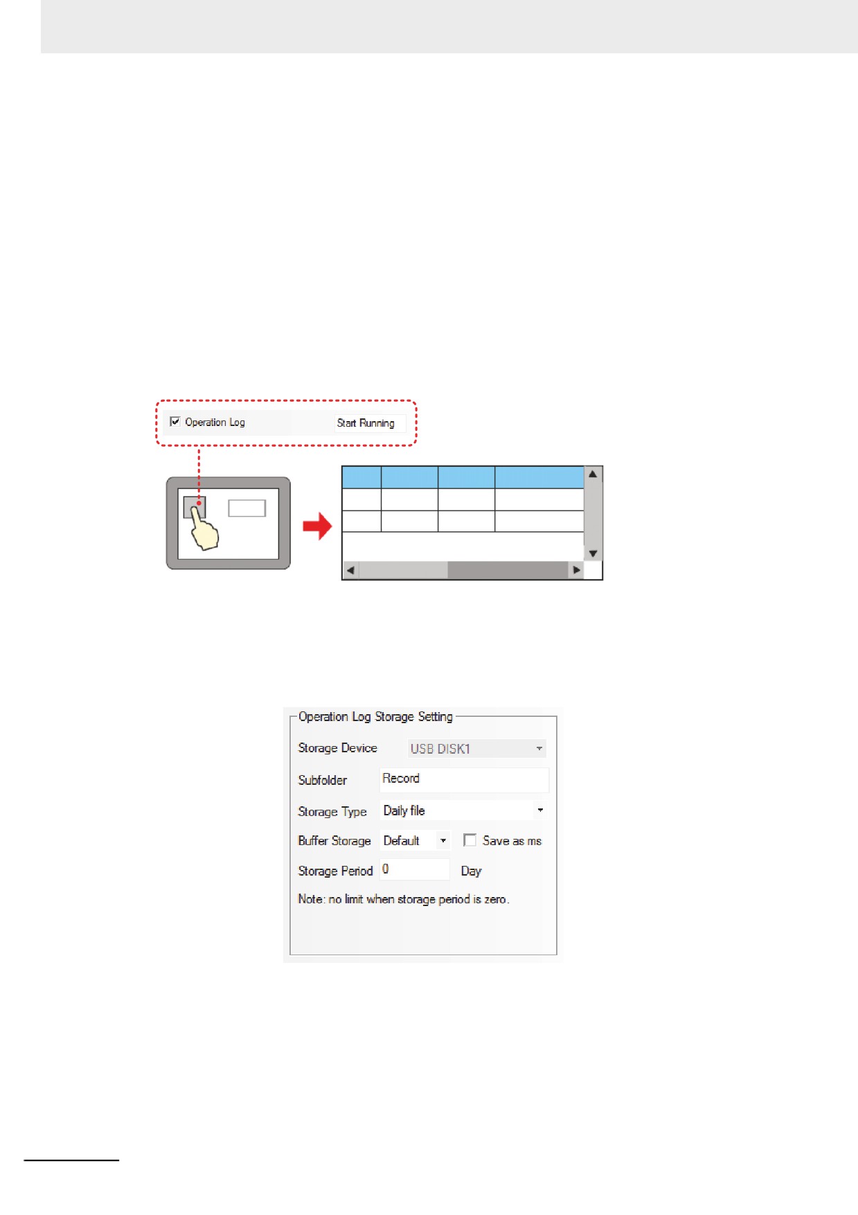
Storage of Operation Log
When the Operation Log component is used, the path for storing the log file should be set in the
[Operation Log Storage Setting] option in the [PT Extended Properties] tab in the [PT Property] dia-
log box.
For the output file in CSV format, if the [Daily File] is selected, the file storage path is “log/subfolder
name/yyyymmdd.csv”, and if the [Single File] is selected, the storage path is “log/subfolder
name/subfolder name.csv”. (Where, yyyymmdd is the created date of the operational records. For
example: 20110101)
Settings of the components for Operation Log
For the component with the requirement of displaying the Operation Log in the Operation Log, it
needs to check the [Operation Log] option in the [Security Setting] part in the [Control Setting] tab in
the property dialog box of the component on which should be operated.
No. Date Time
Log
0
11/06/24
11:23:20
Parameter Corr
123
1
11/06/24
11:22:45
Start Running
z Saving the related information into the external memory:
The related information can be stored in the external memory by using the “Operation Log Storage
Setting” option in the [PT Extended Properties] tab in the [PT Property] dialog box, as shown below.
6-10