OMRON NB-Designer OPERATION MANUAL (NB-series, 2020) - page 15
3 Functions of NB-Designer
13 Use Input Order
The Number Input component, Text Input component and Note Book component have this
function.
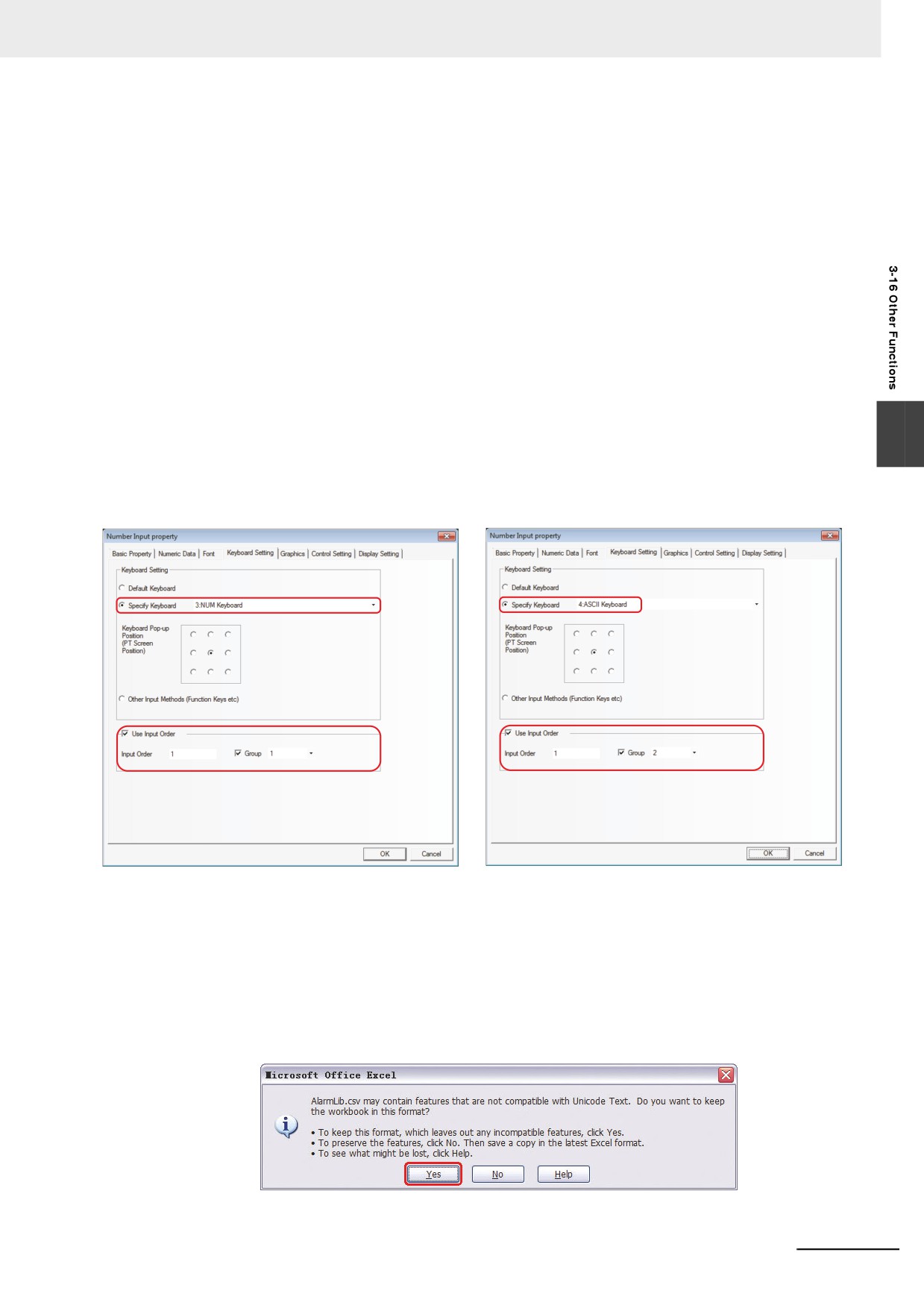
Using the [Use Input Order] allows continuous input to Number Input component, Text Input
component, and Note Book component. Even if the “Enter” button is pressed, the keyboard will
not be closed automatically and will be kept to be opened and the cursor using [Use Input
Order] keeps moving among the components until the screen is closed by pressing “X” in the
top of the keyboard.
[Group] is used to classify the multi-group of components needing consecutive inputs. The
components with the same group number belong to the same group, and the cursor will be
cyclic in the same group of components. When the “Enter” is pressed, the keyboard will not be
closed automatically, but will always be displayed in the screen until the close button “X” in the
keyboard is clicked.
Setting of [Use Input Order]
3
Go to the [Keyboard Setting] Property tabs for the Number Input component, Text Input
component and Note Book component respectively, and check the [Use Input Order].
14 [Import/Export] of Background Component
The background component including [Variable Table], [Text Library], [Alarm Setting], [Event
Setting] and [PLC Control] has the function of importing or exporting the file in .csv format. This
function is convenient to edit the related contents through the csv directly.
Note:
Please pay attention to the following points when saving the file in CSV format after it is edited.
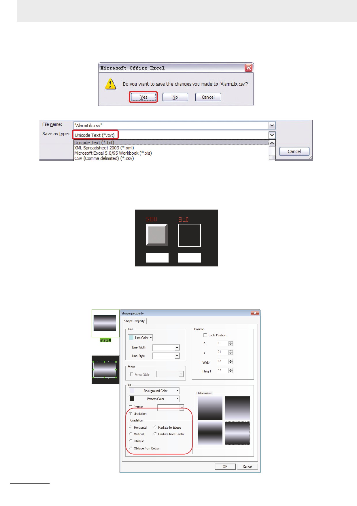
(a) When the csv file is saved in Excel, click [Save] and select [Yes] as shown below:
3-383
3 Functions of NB-Designer
(b) After selecting [File] - [Exit] in the menu, a dialog box as follows will be displayed and
select [Yes].
(c)
[Unicode Text(*.txt)]must be selected from [Save as type].
(d) Change the extension of the saved file to csv.
15 Not Display Frame of Component
The frame of the component is not displayed when the component uses the graphics, but
displayed when the component doesn’t use the graphics, as shown below:
no display
display
16 Gradation of Static Graphics
Gradation adds the effects to fill the graphics. And this function is useful for drawing the Vector
Graphics such as the piping with the gradation effect, as shown below:
3-384
3 Functions of NB-Designer
17 Polygon Overall Zoom
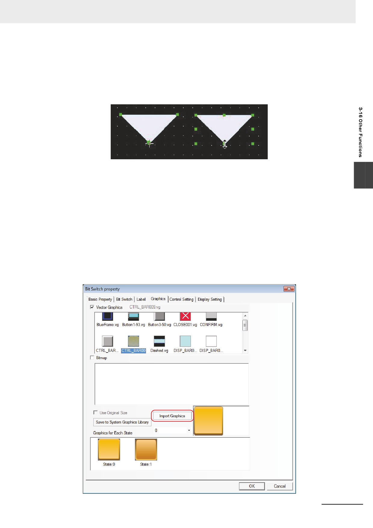
The “Overall zoom in/out” added to the polygon allows the resizing without changing the shape.
After the component is clicked to turn into selecting state, one more click allows the editing the
top of the polygon. In the case, the cursor is turned to be appeared as “+” as follows. When the
cursor is appeared as “<->”, “Overall zoom out/in” can be performed.
18 Graphics Library
3
The display area is divided into two parts. All the graphics in the graphics library will be
displayed in the upper part while each state of the selected graphics will be displayed in the
lower part.
Bitmap and Vector Graphics are supported. Bitmap in .bg format is made of images in .bmp,
.gif, .jpg or .png formats or pictures. Using too many bitmaps will affect the operation speed of
PT. Therefore it is recommended to use the Vector Graphics to replace the bitmaps as much
as possible. The Vector Graphics in .vg format is drawn by the NB-Designer using the point,
line and circle, etc.
There are 3 methods to enter the Graphics Library window.
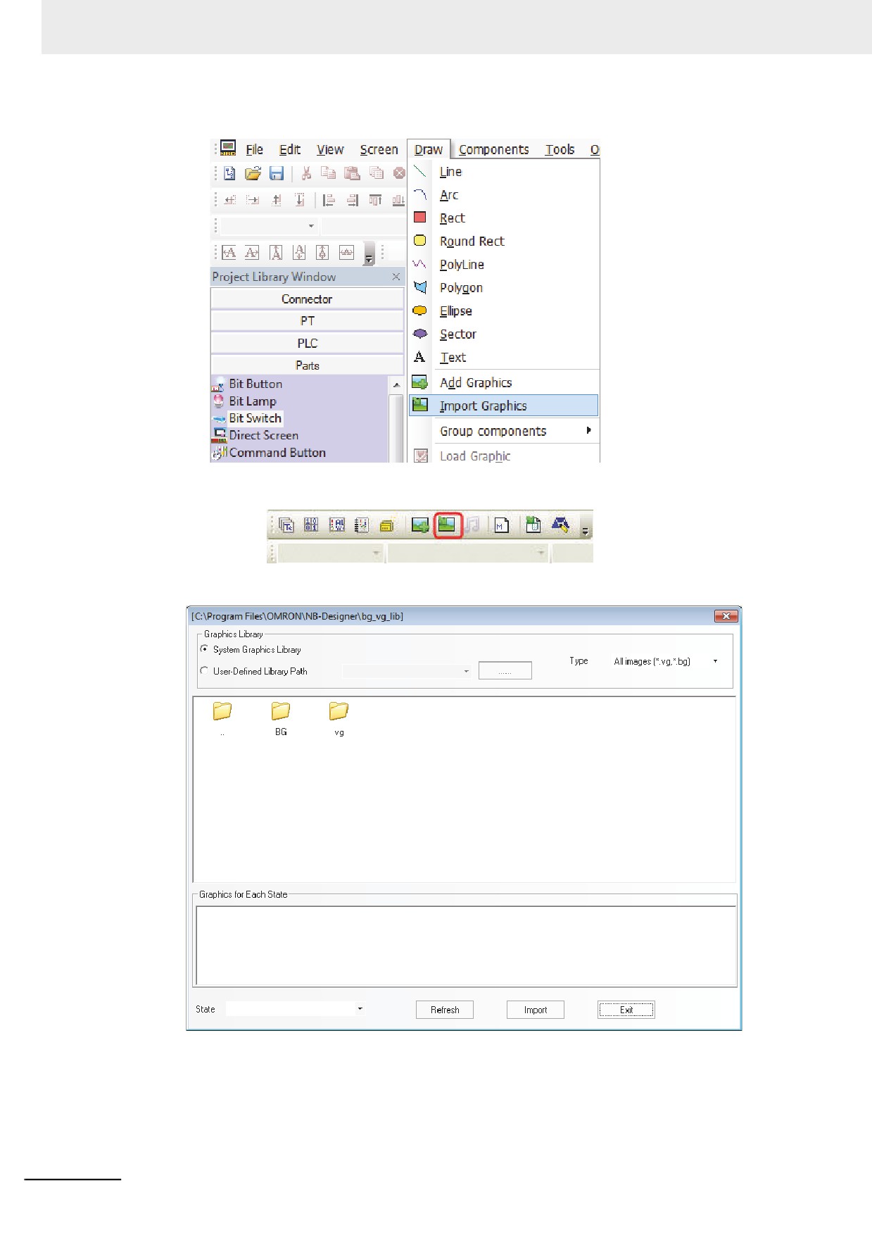
(1) Click [Import Graphics] in the [Graphics] tab in the component Property dialog box to enter
the grapchics library window (As shown below, take the Bit Switch component as example,
and the other components are similar.)
3-385
3 Functions of NB-Designer
(2) Select [Import Graphics] in [Draw] menu to enter the Graphics Library window.
(3) Click [Import Graphics] icon in the toolbar to enter the Graphics Library window.
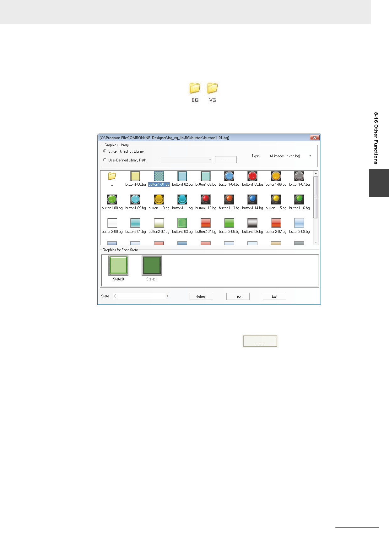
The Graphics Library window is shown as below:
3-386
3 Functions of NB-Designer
There are 2 methods for selecting the Graphics Library:
(1) System Graphics Library: It is the graphics library provided by the software, it is under the
[bg_vg_lib] folder in the installation folder of the software.
Double-click [BG] or [vg] folder
, and then the bitmap images or vector graphics
installed by default will be displayed. The display area is divided into two parts. And all the
graphics in the graphics library will be displayed in the upper part while each state of the
selected graphics will be displayed in the lower part, as shown below:
3
(2) User-Defined Library Path: The folder is specified by the user to store the graphics library.
With this option, graphics in the other projects can be imported. The graphics used in each
project is saved in [vg] file for the project. Clicking
can reveal the file path.
The method of importing graphics is as follows:
Select one graphics, then click the [Import] button to import the graphics in the Graphics
Library to the project. Each time only one graphics instead of many can be imported to the
project.
3-387
3 Functions of NB-Designer
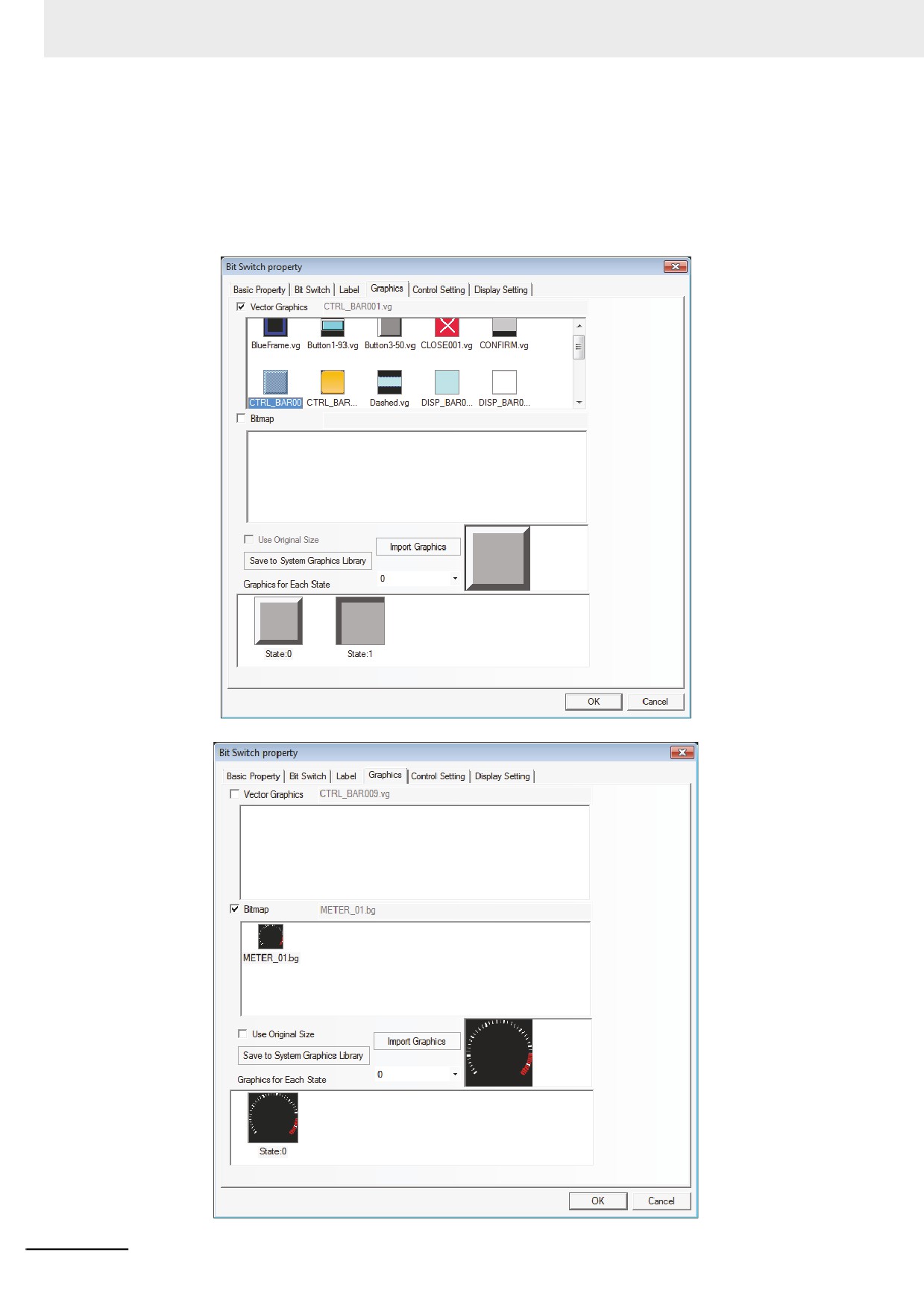
The method of using graphics:
Right-click the mouse on the selected component and select “Property” in the pop-up
menu, then go to [Graphics] tab to check Vector Graphics or Bitmap. The Vector Graphics
is checked by default. When [Vector Graphics] is checked, all the Vector Graphics
contained in the current project will be listed in the selection box of Vector Graphics, and all
the states of the selected graphics will be displayed in the [Graphics of Each State]
selection box, as shown below.
3-388
3 Functions of NB-Designer
If new graphics needs to be added, click [Import Graphics].
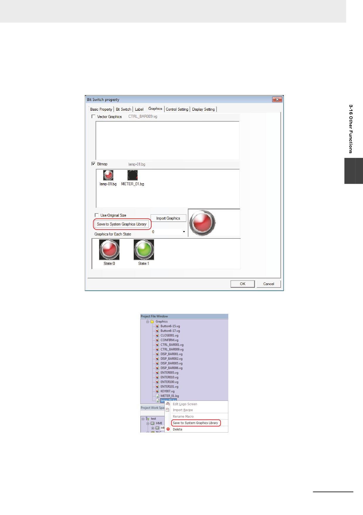
Role of [Save to System Graphics Library] is to save the current graphics to the software for
the convenient call during the creation of other projects.
There are 2 methods for [Save to System Graphics Library]:
(1) Enter the [Graphics] tab and click [Save to System Graphics Library].
3
(2) Enter the [Graphics] in [Project File Window], select the current graphics, and right-click the
mouse to select [Save to System Graphics Library].
[Use Original Size] is intended for the user to conveniently make the graphics return to its
original size after it is zoomed out or in.
3-389
3 Functions of NB-Designer
19 Support Graphics in GIF or PNG Format
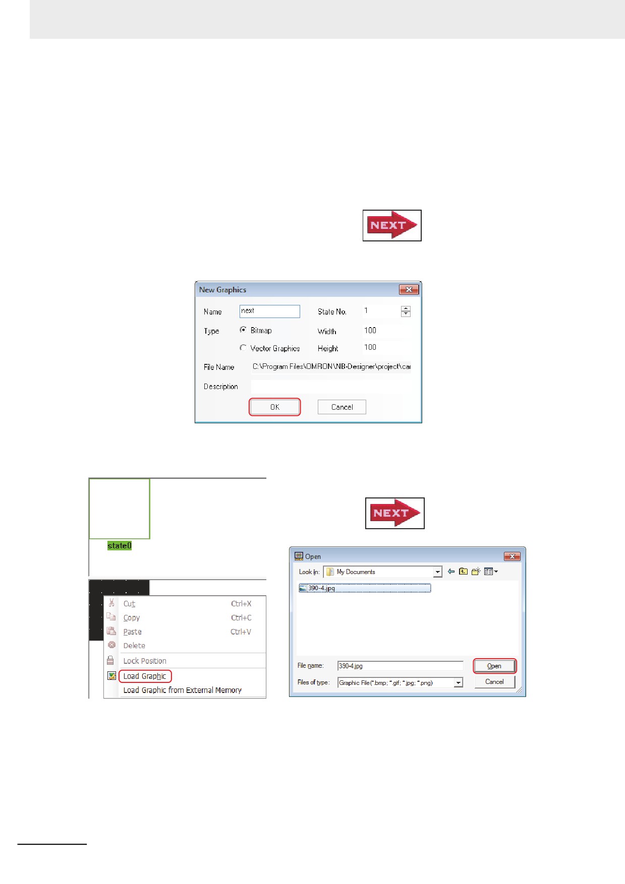
The graphics in .gif or .png format can be imported directly during the creation of new graphics.
Using the graphics in .gif format can create the animation effect easily.
Using the graphics in .png format can create the transparent effect easily. For example, if the
Level Meter is added into the reaction vessel to show the current liquid level, then one reaction
vessel in .png format is needed.
For example:
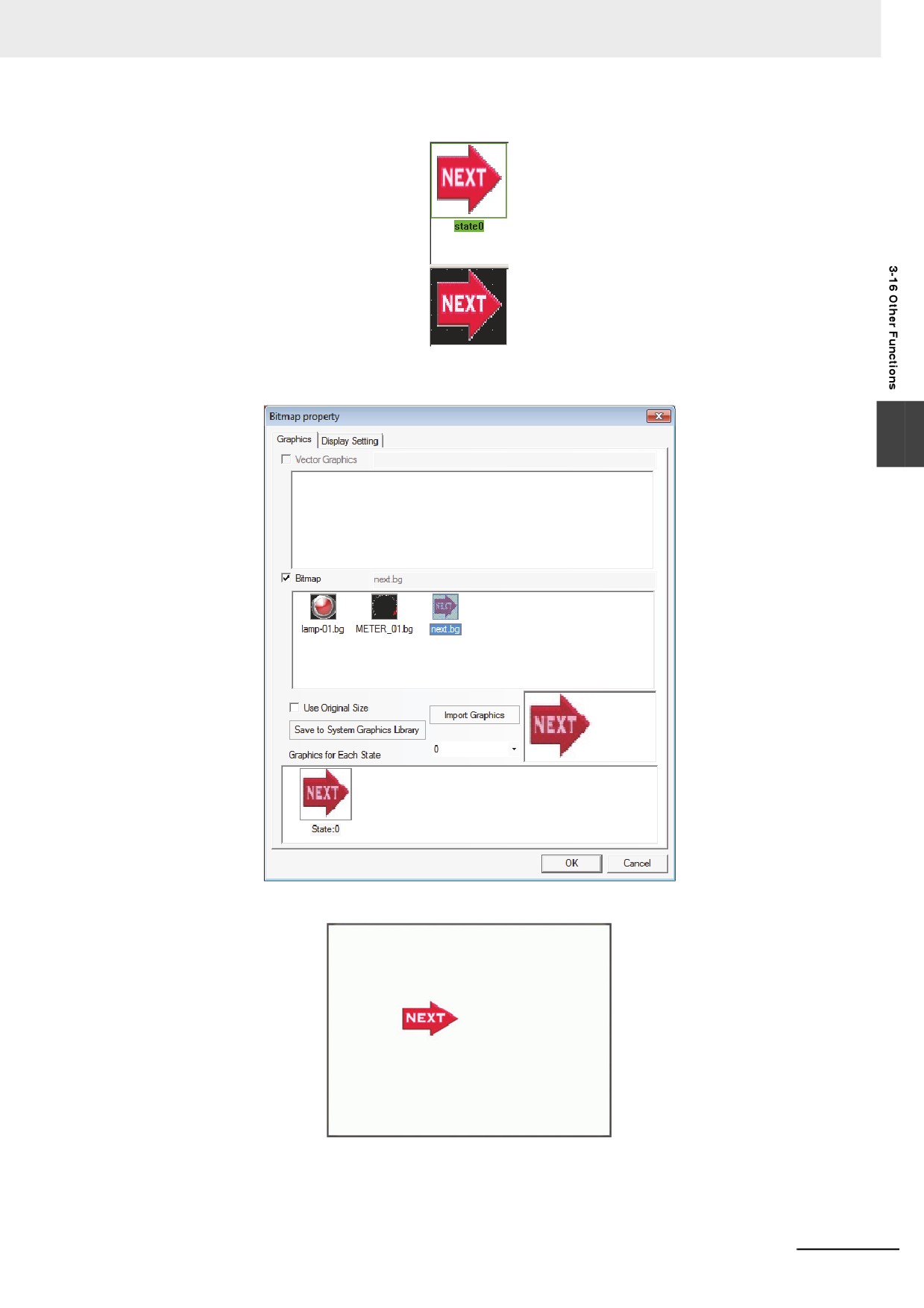
Use one graphics in .gif format with the effect like
(1) Click [Draw] menu to select [Add Graphics], and set the Name to “next”, Type to [Bitmap]
and other options to the defaults.
(2) Click the [OK] button to make the following editing box appear, and select [Load Graphic]
after right-clicking the mouse in the black editing box.
Select the graphics
3-390
3 Functions of NB-Designer
The successful import of graphics is as shown below:
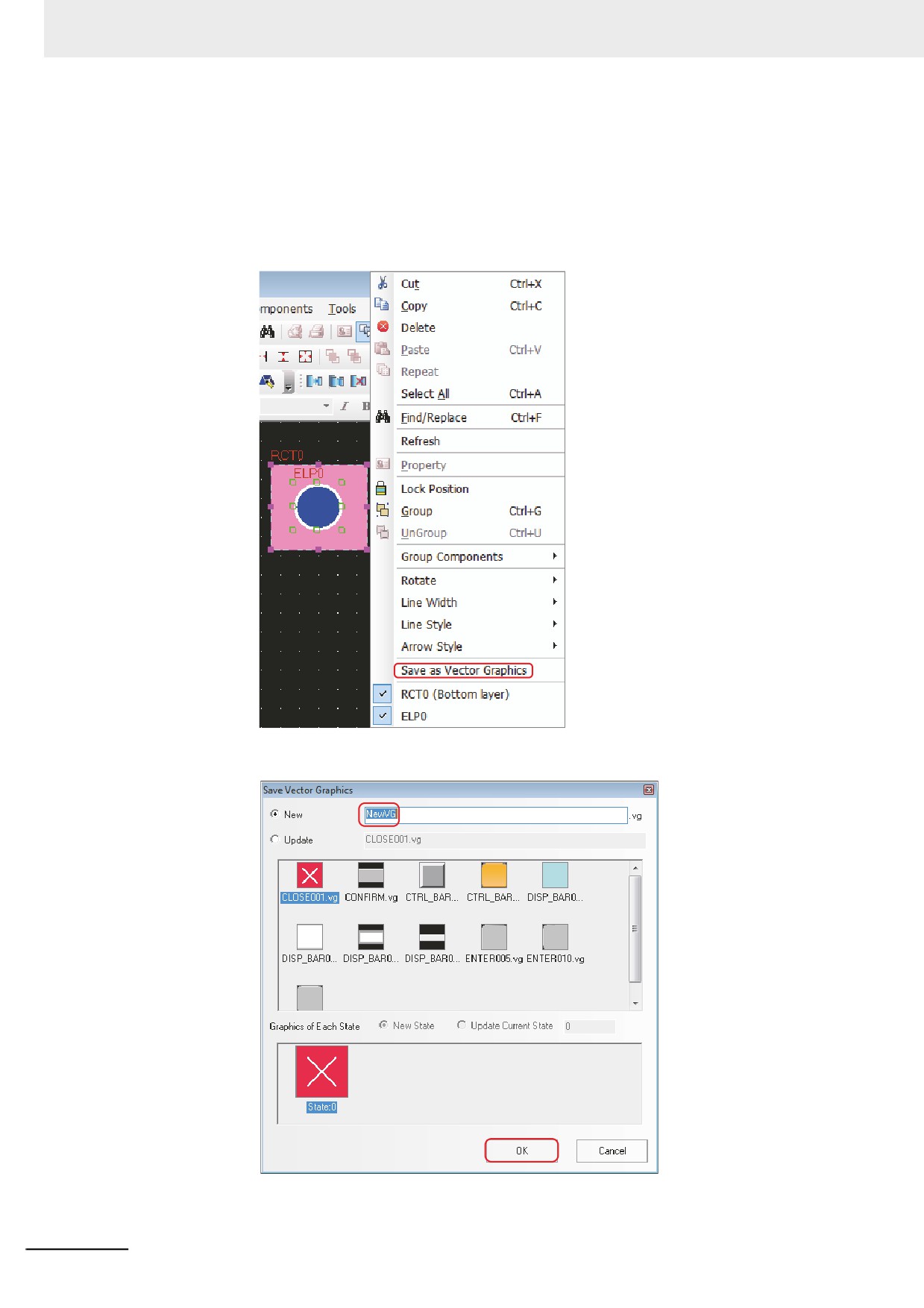
(3) After saving the project, quit from the graphic edit window and enter the edit window.
(4) Place one Bitmap component, and check [Use Original Size].
3
(5) When the offline simulation is performed, and the effect is as shown below:
3-391
3 Functions of NB-Designer
20 Save as Vector Graphics
Storing the graphics created from multiple graphic components allows the diversion to the
other screens.
The operation is as follows:
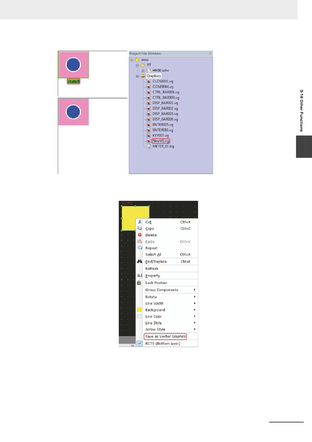
(1) Draw a rectangle and a circle, then select these two components and right-click the mouse
to select [Save as Vector Graphics].
(2) In the pop-up [Save Vector Graphics] dialog box, [New] is checked by default, and the
default name is NewVG. Click the [OK] button.
3-392
3 Functions of NB-Designer
Then the creation of a new VG graphics with only one state (state0) is completed.
3
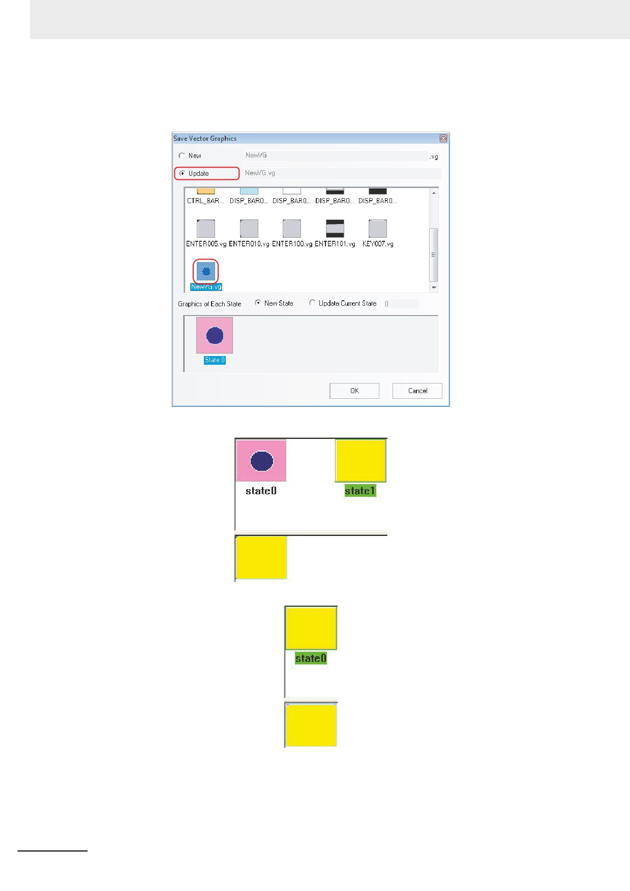
(3) For the addition of a Round rectangle into state1.
Draw a Round rectangle and select it, then right-click the mouse and select [Save as Vector
Graphics].
3-393
3 Functions of NB-Designer
(4) Check in the [Update] radio button in the [Save Vector Graphics] dialog box and select a
NewVG.vg file. Then, select the state of the graphic to save the file.
[New State]: State1 will be added.
[Update Current State]: State0 will be replaced.
[Save to System Graphics Library]: The new created NewVG.vg will be saved to the system
library for the convenient call of this graphics by the other projects. For the method to call
graphics, refer to the 18 Graphics Library (Page 3-385).
3-394
3 Functions of NB-Designer
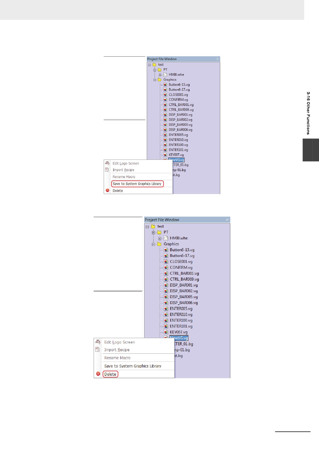
Method of [Save to System Graphics Library]: Select the NewVG.vg in [Project File
Window], then right-click the mouse to select [Save to System Graphics Library].
3
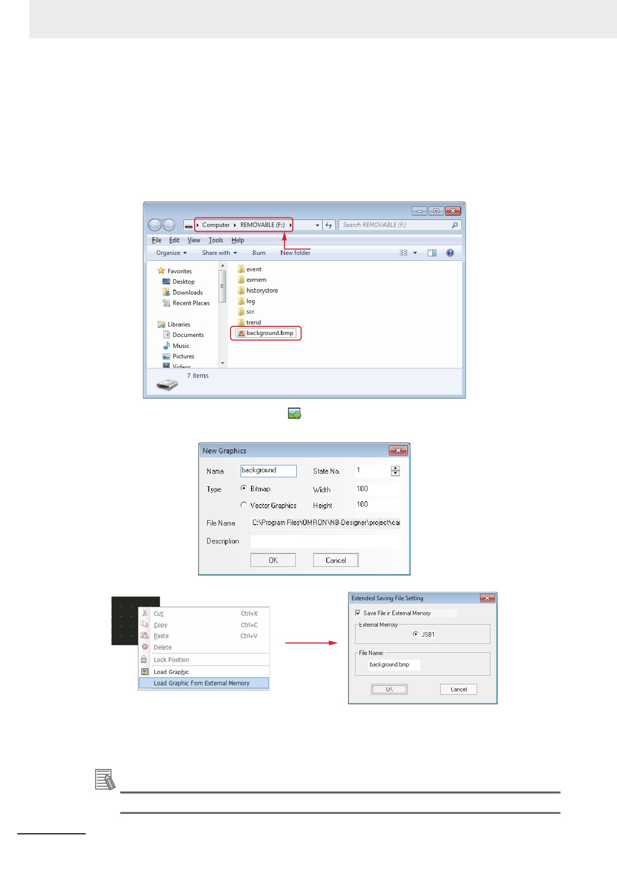
[Delete] (Method of deleting the new created NewVG.vg): Select the NewVG.vg in [Project
File Window], then right-click the mouse to select [Delete].
3-395
3 Functions of NB-Designer
21 Using Graphics From External Memory
NB-Designer also supports the bitmap data directly calling the graphics from the external
memory in order to save the memory space of the PT.
For example:
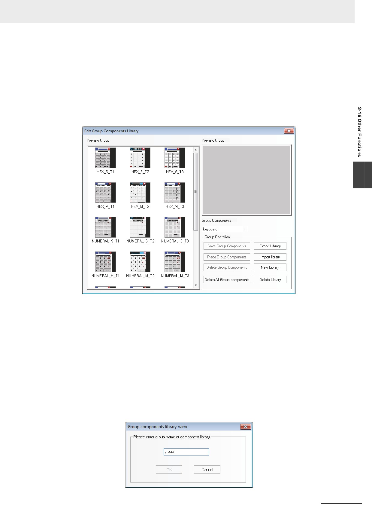
Create a background picture named “background.bmp” and save it in the root folder of external
memory (Here refers to USB1). Then the project will directly call the picture named
“background.bmp” from external memory.
(1) Copy the picture named “background.bmp” into the root folder of external memory.
Root Directory
(2) Create new graphics: Click the icon in the toolbar or select “Add Graphics” option in the
[Draw] menu; and enter “background” in the Name option, select “1” in State No. option and
check “Bitmap” in Type option after the [Add Graphics] dialog box pops up.
(3) Specify the setting for graphics which is called from external memory in status editing area.
Note 1
[File Name] must be same as that of the bitmap to be called from the external memory.
2
The formats of the graphics which can be called from external memory are BMP, JPG, and GIF only, not PNG.
3
The pictures must be saved in the root folder of the external memory.
(4) The creation of background picture is completed, and then exit from this operation after save it.
Additional Information
The display will be updated without the restart by turning LB9108 ON.
3-396
3 Functions of NB-Designer
22 Group Components
Several components or the graphics are combined together and saved into the Group
Components Library, thus making them called by other projects conveniently.
The format of Group Components Library is .pgl.
(1) Method of entering [Edit Group Component Library]
Click [Use Group Component] in [Group components] in [Draw] menu or right-click the mouse
in the blank area of the window the select [Use Group Component] in [Group Components],
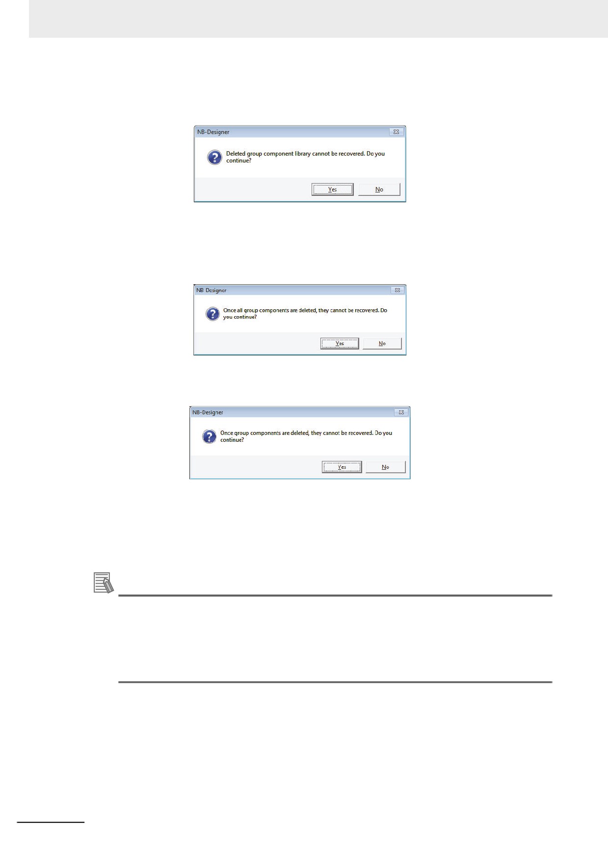
then the [Edit Group Components Library] dialog box will pop up, as shown below:
3
[Export Library]
Clicking [Export Library] can make the [Group Components Library] saved to the folder
specified.
[Import Library]
The default path of group components is the usrlib folder under the installation path of NB-
Designer, and the user can also import the group components library from the self-defined
path. Click [Import Library], and select the required group components library in the path
corresponding to the saved group components library, then click [Open] to add this group
components library to the group components library of the current project.
[New Library]
Clicking the [New Library] button will make the following dialog box pop up, and the user
can input the name of this new created group components library in it. The default path to
save the group components library is the usrlib folder under the installation path of the
software.
3-397
3 Functions of NB-Designer
[Delete Library]
Clicking the [Delete Library] button will delete the group components library opened
currently.
Clicking “Yes” will delete the current group components library from this project, while
clicking “No” will ignore the operation done just now.
[Delete All Group Components]
Clicking the [Delete All Group Components] button will delete all the components in the
group components library opened currently.
[Delete Group Components]
Clicking the [Delete Group Components] button will delete the components in the group
components library opened currently.
Note
“Delete Library”, “Delete Group Components” and “Delete All Group Components” will directly
delete the related files in the usrlib folder under the installation path of the NB-Designer.
[Place Group Components]
Clicking the [Place Group Components] button will place the selected components in the
group components library opened currently into the screen edited currently.
Additional Information
• Some group components contain macros. If a macro with the same file name already exists in
the project in which the group component is to be placed, the macro information will be output
as a MacroConflict.txt file to the folder of the project in which the group component is placed.
• Some group components contain the PLC address information. If the project in which a group
component to be placed does not have the same PLC, the information will be converted to
LB0/LW0.
3-398
3 Functions of NB-Designer
For example:
How to add group components to a new created group components library is described as follows:
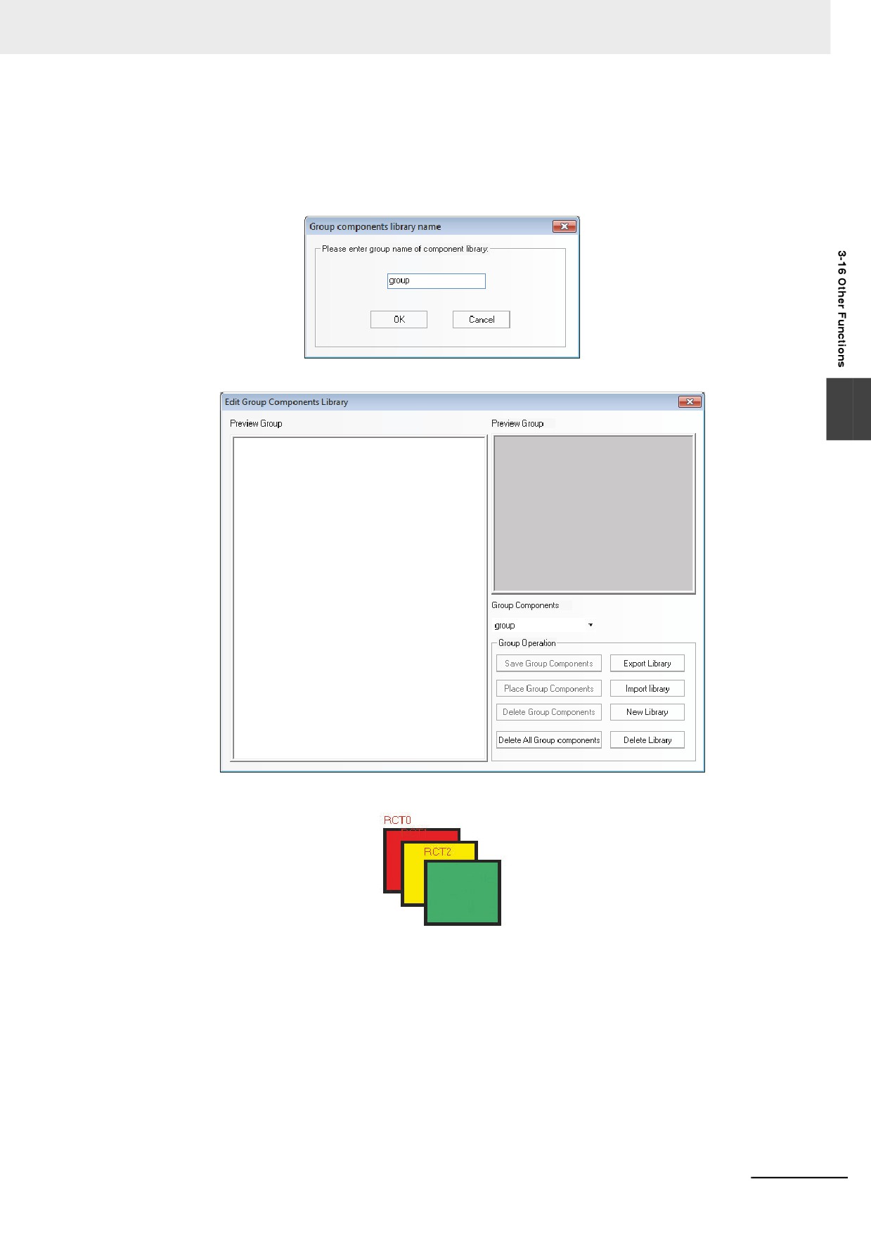
(1) Click [Use Group Components] in [Group components] in [Draw] menu, and click [New Library]
after the Edit Group Components Library pops up, and input “group” as the name of the group
components library in the Group component library name dialog box, as shown below:
Click the [OK] button to create an empty group components library as shown below:
3
(2) Place 3 rectangles in the screen, as shown below:
3-399
3 Functions of NB-Designer
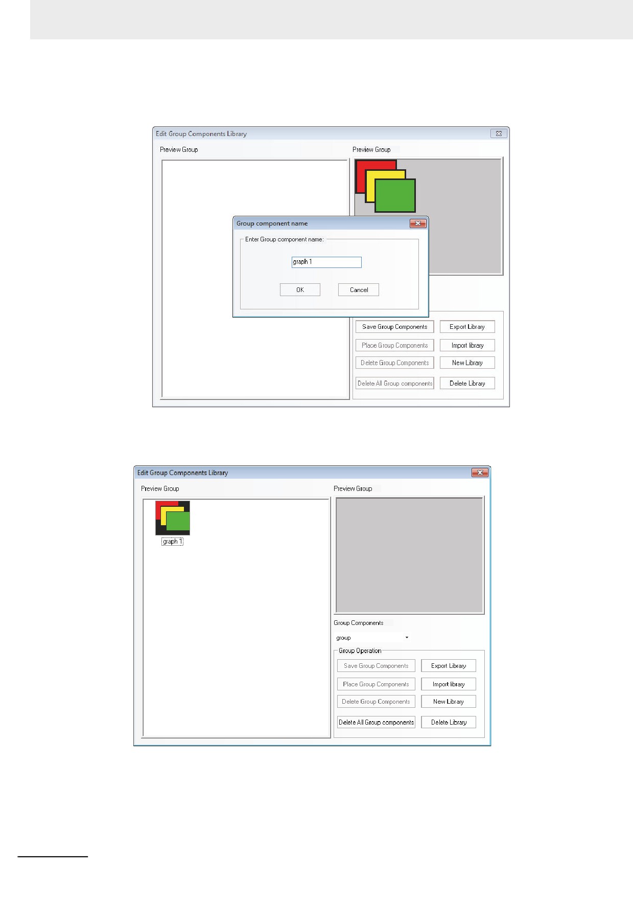
Select these 3 rectangles, and right-click the mouse to select [Group Components] - [Save
Group Components], and then click the [Save Group Components] button in the Edit Group
Components Library dialog box to make the following dialog box pop up.
(3) Input “graph 1” in the Part Group Name dialog box and then click the [Ok] button, then
these 3 rectangles with the name of [graph 1] will be added into the new created group
components library with the name of [group], as shown below:
(4) If there are other group components to be added into the group components library with the
name of [group], the operation method is the same as that mentioned above. And you just
need to select [group] in the Group Components location in Edit Group Components Library
dialog box as the path to save it.
3-400
3 Functions of NB-Designer
23 Edit Group Components
Group components can be edited remaining grouped.
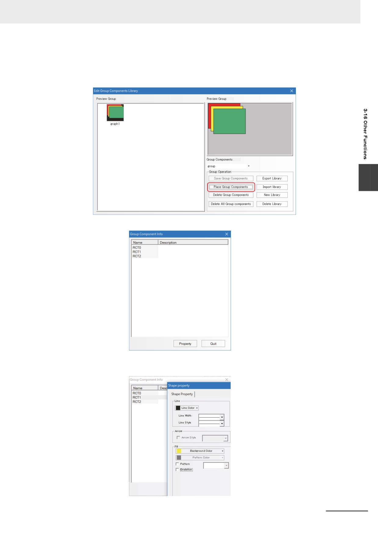
(1) Select [Place Group Components] in [Edit Group Components Library].
3
(2) Double-click a group component to display the [Group Component Info] dialog box.
(3) Select a component and open the property window to change the component's settings
remaining grouped.
3-401
3 Functions of NB-Designer
24 Usage of Keyboard
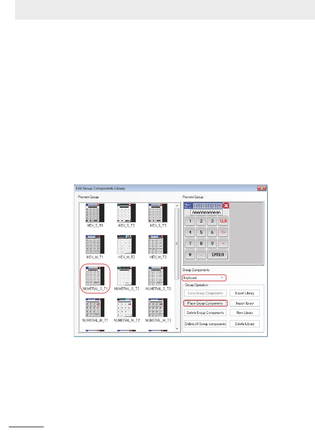
NB-Designer provides 21 default keyboards in [Group Components Library], and the
keyboards are as follows:
3 small keyboards with different styles: HEX Keyboard (HEX_S_T1 to HEX_S_T3), NUM
Keyboard (decimal, NUMERAL_S_T1 to NUMERAL_S_T3) and ASCII Keyboard (ASCII_S_T1
to ASCII_S_T3), which are applicable to the small PT with the resolution not more than
320×240.
3 middle keyboards with different styles: HEX Keyboard (HEX_M_T1 to HEX_M_T3), NUM
Keyboard (decimal, NUMERAL_M_T1 to NUMERAL_M_T3) and ASCII Keyboard
(ASCII_M_T1 to ASCII_M_T3), which are applicable to the large PT with the resolution not less
than 640×480.
3 small grey decimal NUM Keyboards with different styles: NUMERAL_S_L1 to
NUMERAL_S_L3.
How to call the keyboard in the group components library is described as follows:
(1) Click [Use Group Components] in [Group components] in [Draw] menu, or right-click the
mouse in the blank area in the window to select [Group Components] - [Use Group
Components], then select [keyboard] from [Group Components] in [Edit Group
Components Library], finally select [NUMERAL_S_T1] from [Preview Group] and click the
[Place Group Components] buttons, as shown below:
3-402
3 Functions of NB-Designer
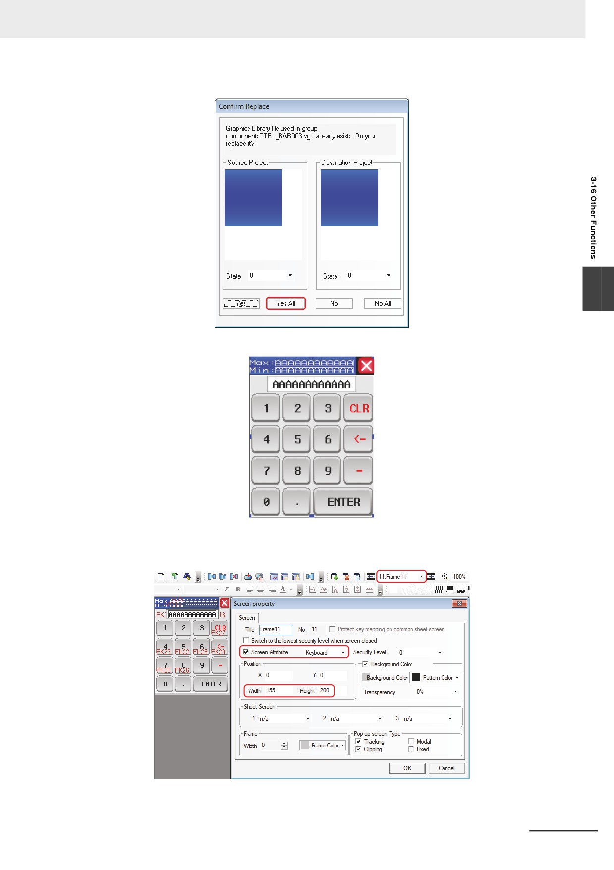
(2) Click the [Yes All] button in the Confirm Replace Dialog.
3
(3) Close [Edit Group Components Library] and one keyboard will appear in the screen.
(4) Place this keyboard in Frame 11, double-click the mouse and change Width and Height,
select [Keyboard] after Special Attribute being checked and make the other settings in
Screen Property dialog box, as shown below:
Note
[Keyboard] in [Screen Attribute] must be selected in [Screen Property] dialog box.
3-403
3 Functions of NB-Designer
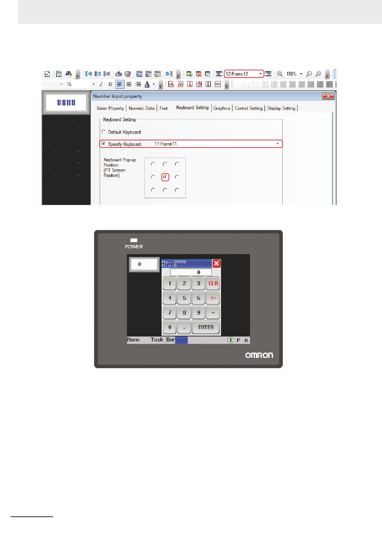
(5) Place one Number Input component in Frame 12, and select [Specify Keyboard] in
[Keyboard Setting] tab, as shown below:
(6) Perform the offline test and click the Number Input component to make the keyboard pop
up, as shown below:
3-404
3 Functions of NB-Designer
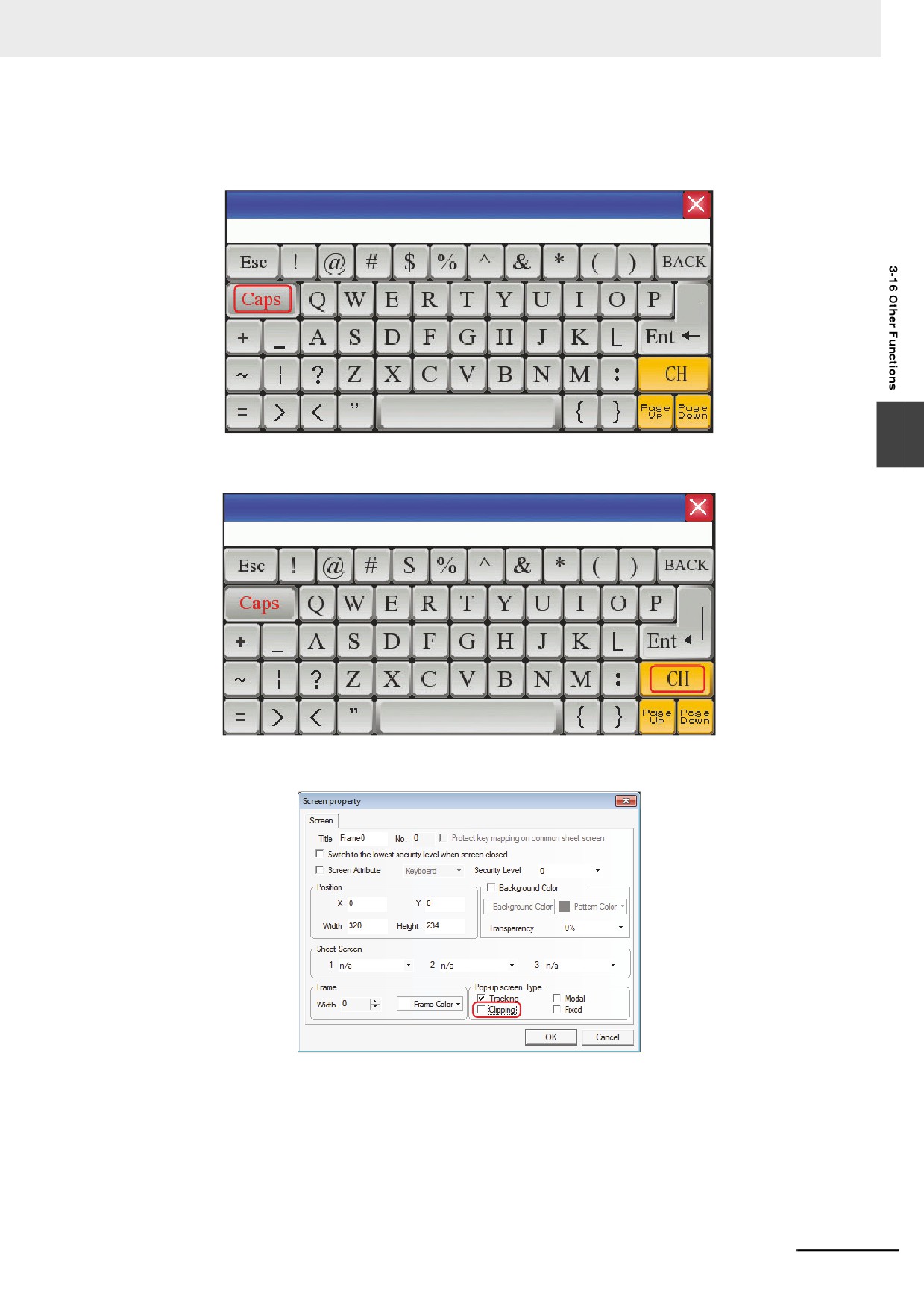
The usage of ASCII keyboard is described as follows:
(1) Support Case: Pressing the Caps key in the keyboard can realize the case switching, as
shown below:
3
(2) Support Chinese and English Input Methods: Pressing CH key in the keyboard can realize
the switching between Chinese and English, as shown below:
Note If the keyboard is called by the Pop-up Screen, [Clipping] in Pop-up Screen Type must not be checked, as
shown below:
3-405
3 Functions of NB-Designer
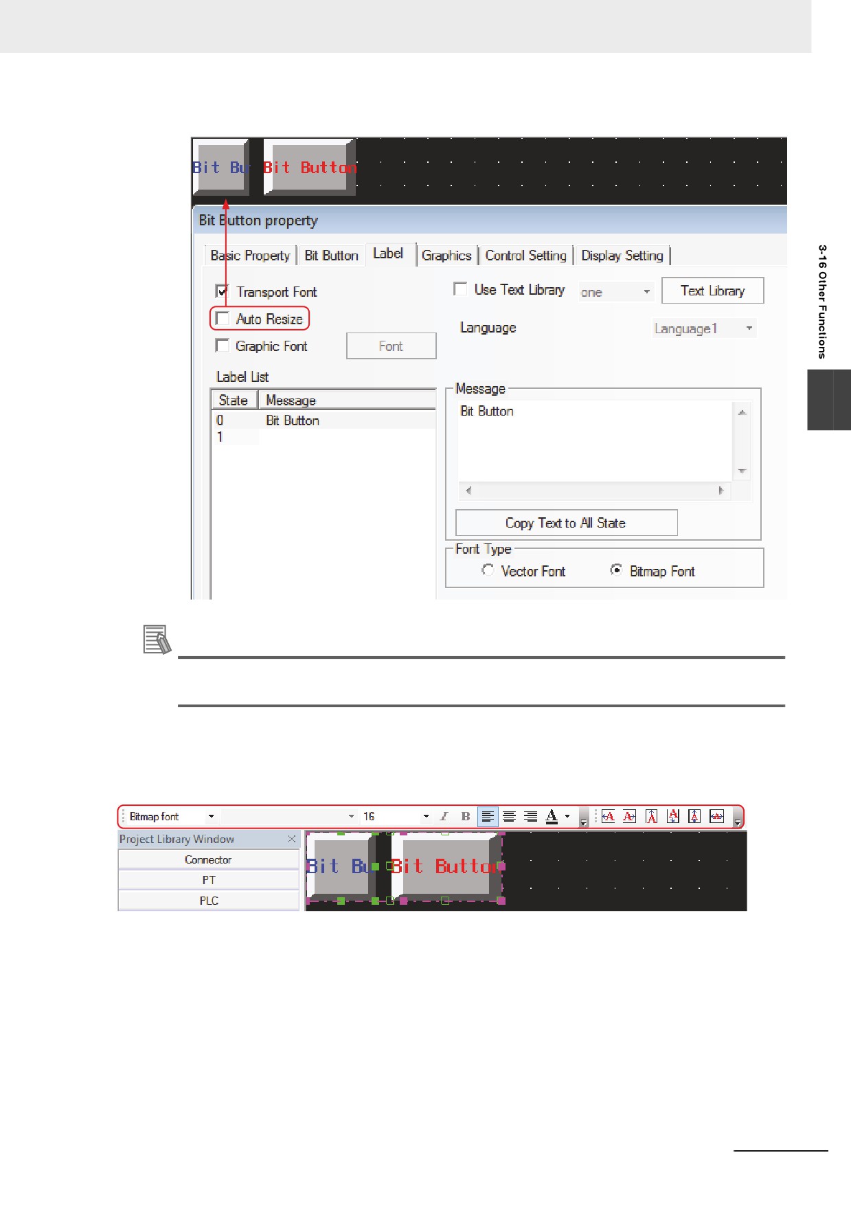
25 Auto Resize
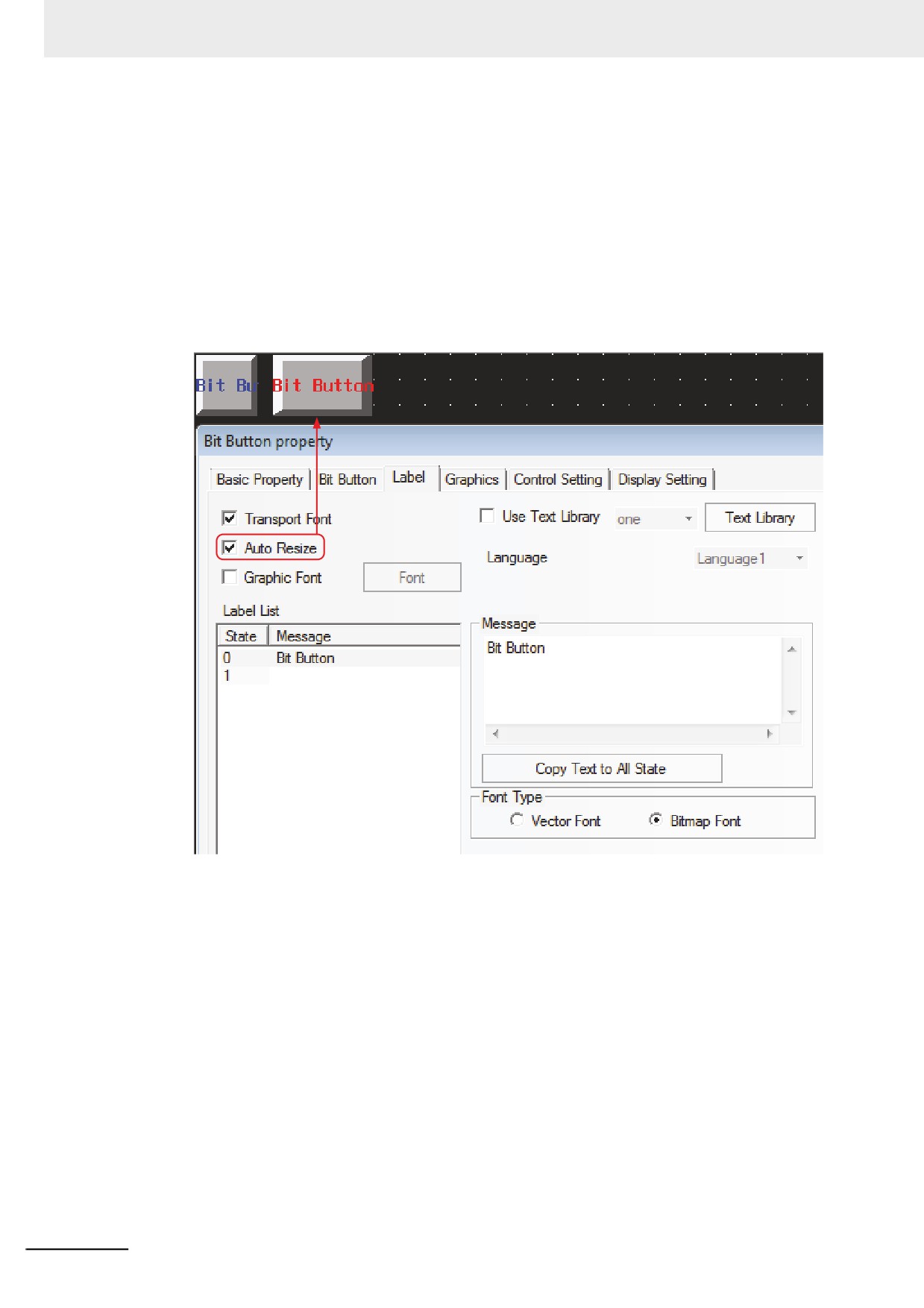
Checking the [Auto Resize] check box in the [Label] tab, when the label is too long or the
multiple languages with different sizes, allows adjustment the size of the component. [Auto
Resize] is checked by default.
After [Auto Resize] is checked, when the length of label exceeds the width of the component,
the component will be extended automatically, thus making all the contents of the label
displayed completely.
If [Auto Resize] is not checked, when the length of label exceeds the width of the component,
the component will not be extended automatically, thus making part of contents of the label
displayed. The effect is shown as below.
3-406
3 Functions of NB-Designer
3
Additional Information
This setting can be temporarily disabled by the setting [Disable Auto Resize] in the [PT Extended
Property].
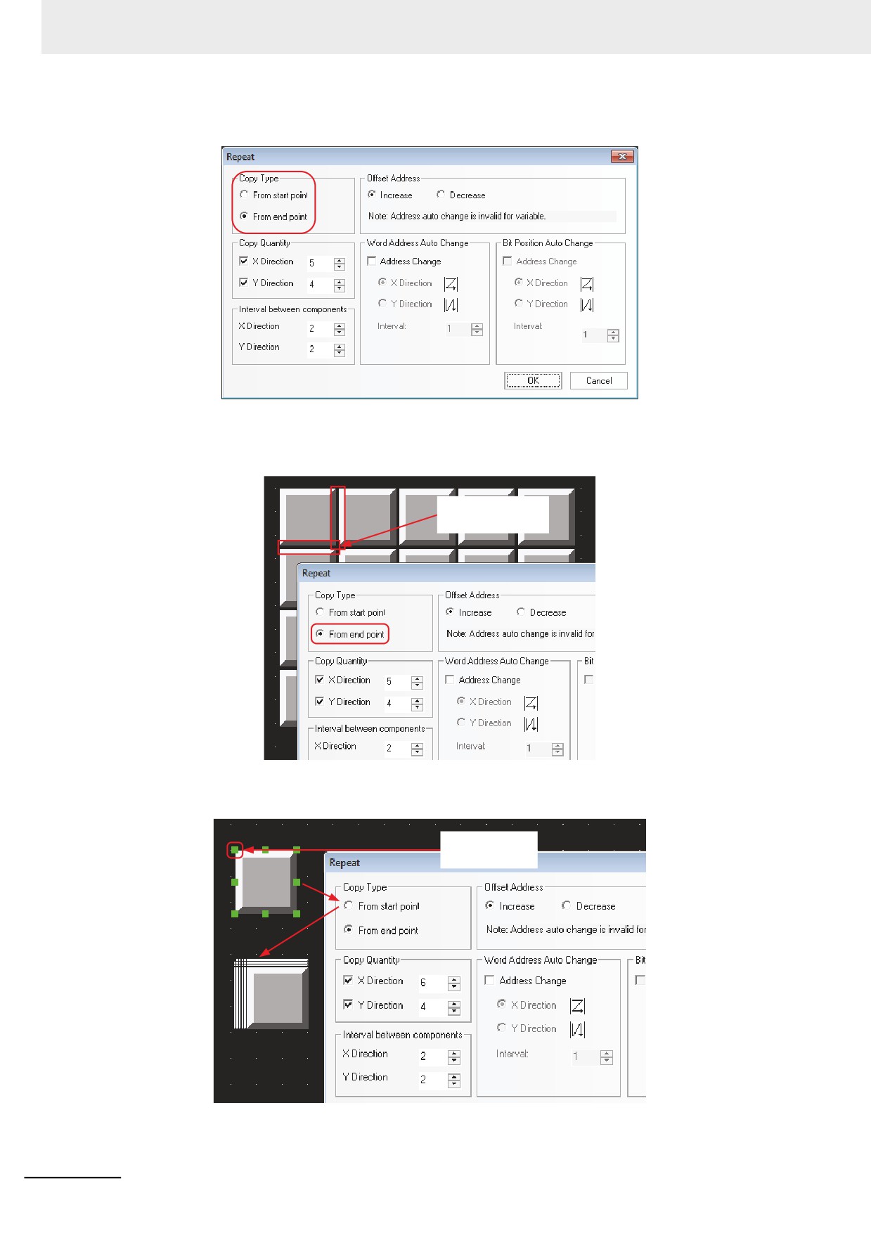
26 Overall Modify Font
Select all the components to be modified, and click each icon in [Font Toolbar] and [Text
Position Toolbar] to overall modify the properties.
3-407
3 Functions of NB-Designer
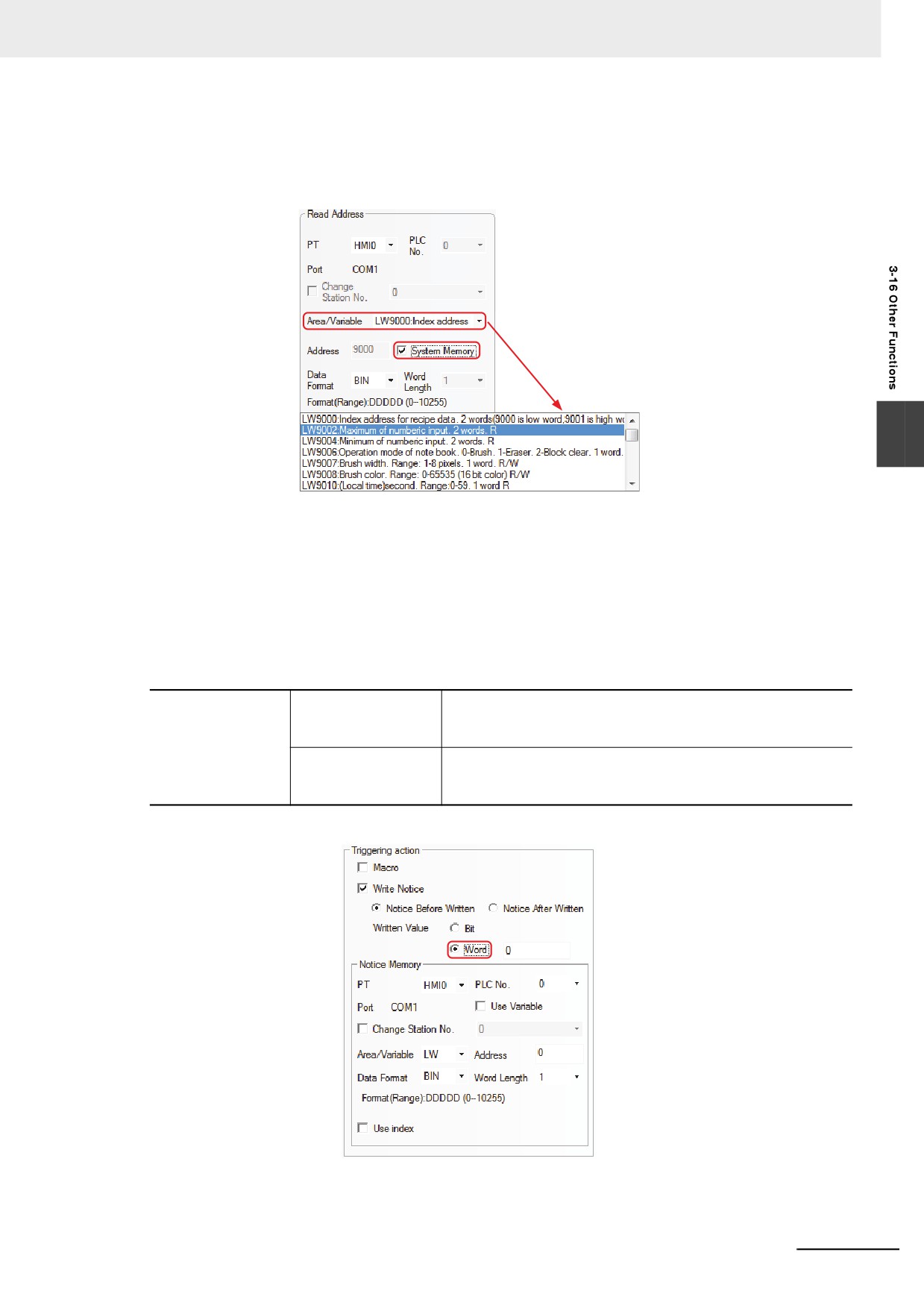
27 Repeat
Difference between [From start point] and [From end point]:
[From end point] specifies the top in the lower right border of the component to the starting
point to copy.
Make the right border
as the start point
[From start point] specifies the top in the upper left corner of the component to the starting point
to copy.
Make this point as
the start point
28 Conveniently Use System memory
3-408
3 Functions of NB-Designer
If you want to use or check the System memory, check the [System Memory] check box in
Basic Property dialog box. The descriptions of all the bit system memories or word system
memories are listed in [Area/Variable], as shown below:
3
29 Simultaneously Open Multiple Projects/Cross-project Copy/Paste
Open 2 NB-Designers. Open 2 projects with different names, and then copy or paste the
current screen by using shortcuts “CTRL+C” and “CTRL+V” or selecting [Edit] - [Copy/Paste].
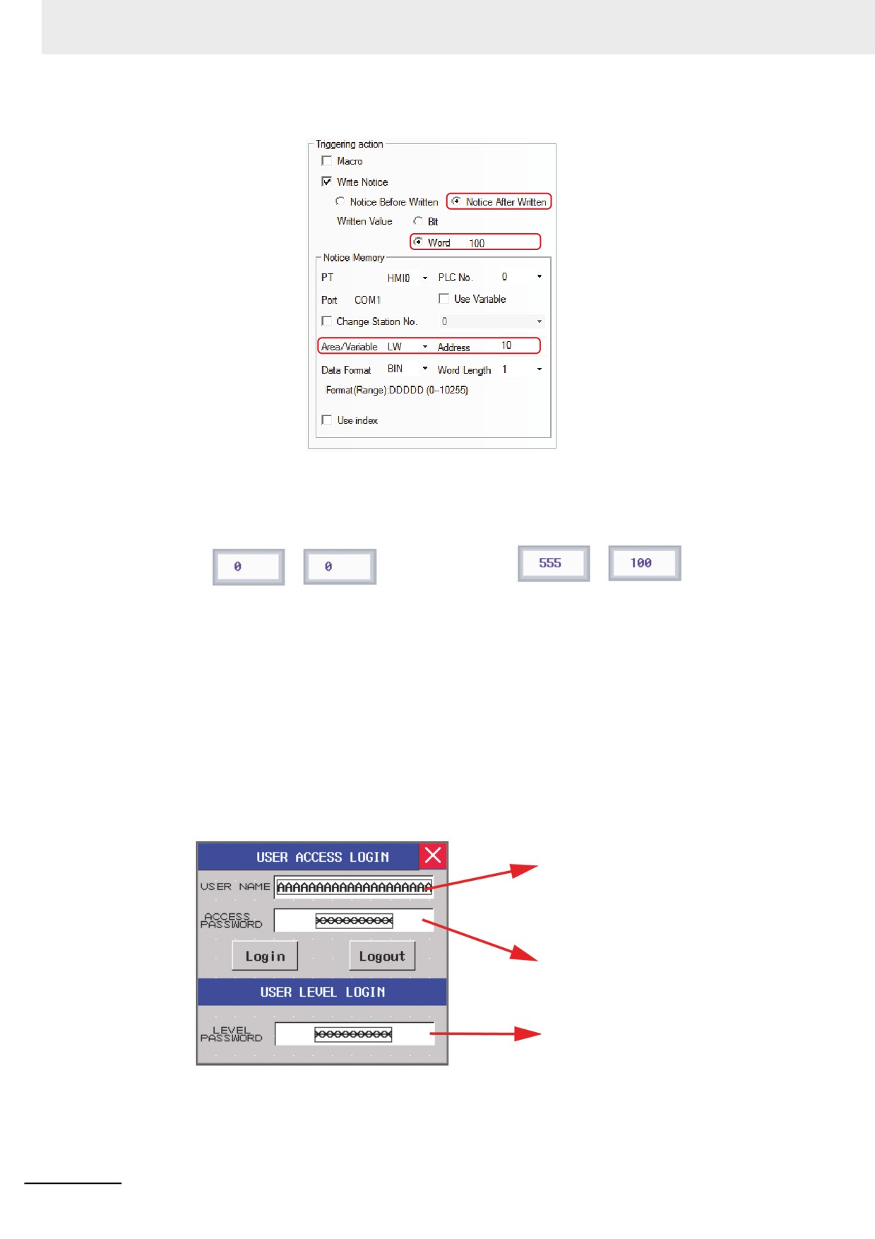
30 Use Notifications Function to Notify Word memory
Notifications to word memories are added in [Control Setting] tab for the Bit Button component,
Bit Switch component, and Number Input component etc.
Write Notice (Word)
Notice Before Written
Makes the write value written into the specified word memory
before the signal of touch component is input into the controller
successfully.
Notice After Written
Makes the write value written into the specified word memory
after the signal of touch component is input into the controller
successfully.
For example, Number Input component LW0 notifies LW10 to write 100 after notification.
Set [Triggering action] in [Control Setting] as shown below:
3-409
3 Functions of NB-Designer
Perform the offline test and the effect is as shown below:
Before data written into LW0:
After data written into LW0:
LW0
LW10
LW0
LW10
Before write value to LW0, LW10=0(defaut value)
After written value to LW0,
LW10 has been noticed to be written value
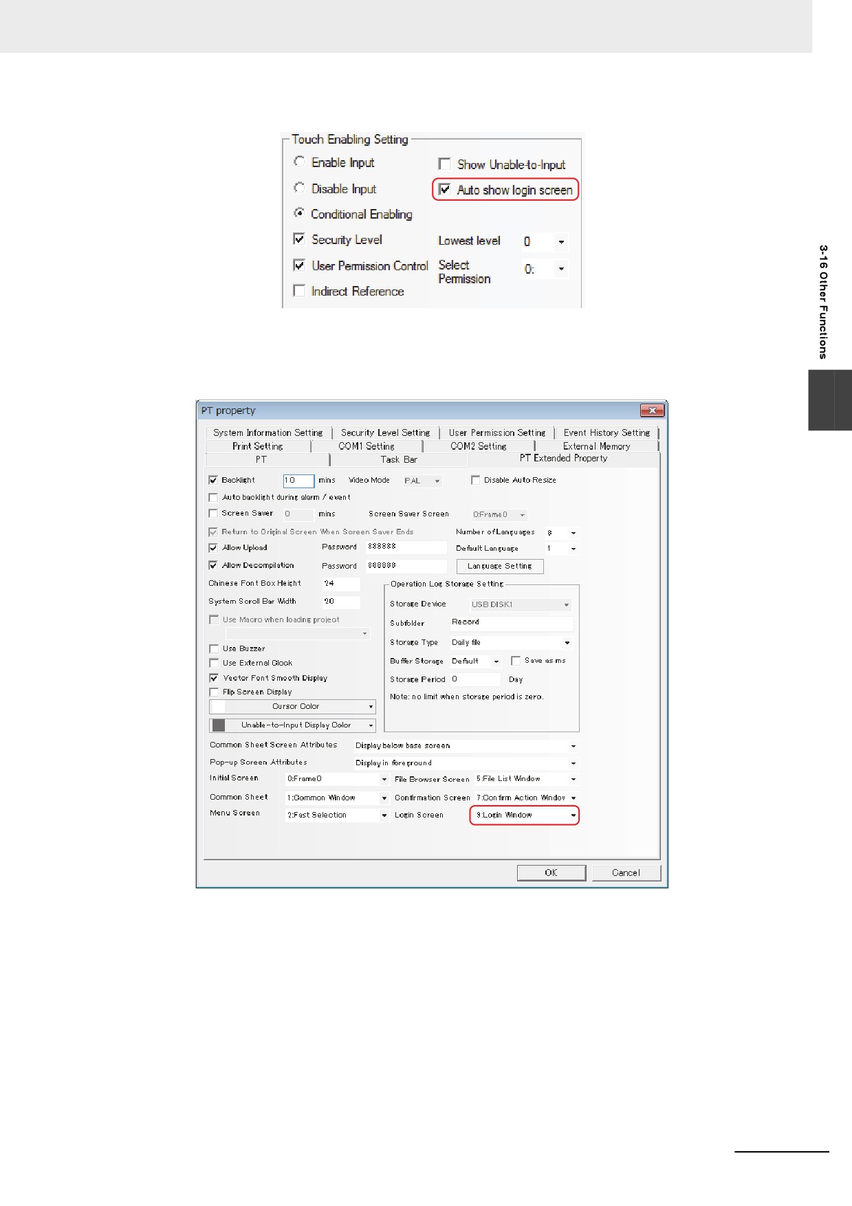
31 Specify “Auto show login screen” to the Component controlled by operations
The [Touch Enabling Setting] in the [Control Setting] tab of the [Component Property] includes
[Auto show login screen] function. NB-Designer makes the Frame9 as the password input
screen (Login Screen), which is convenient for the user to call it when the security level or user
permission is used.
Login Screen includes USER ACCESS LOGIN and USER LEVEL LOGIN screens. You can
input the correct USER NAME and ACCESS PASSWORD and then click “Login” or “Logout” in
USER ACCESS LOGIN screen to complete the login or logout when the user access function
is used; and you can input the correct LEVEL PASSWORD in the USER LEVEL LOGIN screen
to complete the level login when the user level login function is used.
Input box for user name
of user permission
Input box for password
of user permission
Input box for password
of user level
(a) How to set the “Auto show login screen”
Select “Touch Enabling Setting” in [Control Setting] tab in [Properties] dialog box of
control component. Once [Security Level] or [Use Permission Control] is checked,
[Auto show login screen] option will appear, and the “Auto show login screen” check
box is checked, the login screen will pop up automatically.
3-410
3 Functions of NB-Designer
(b) Method to specify a screen as “Login Screen”
Setting the corresponding Login Screen in [PT Property] - [PT Extended Properties]
can make the set screen as the “login screen shown automatically” when the Security
Level or Permission Control function is used.
3
32 FRW, FRB, FRWI, and FRBI memories
FRW, FRB, FRWI and FRBI memories use FLASH to save the data not written frequently.
The data written to the flash memory will not be removed even if the power interruption occurs.
3-411
3 Functions of NB-Designer
33 Index memory
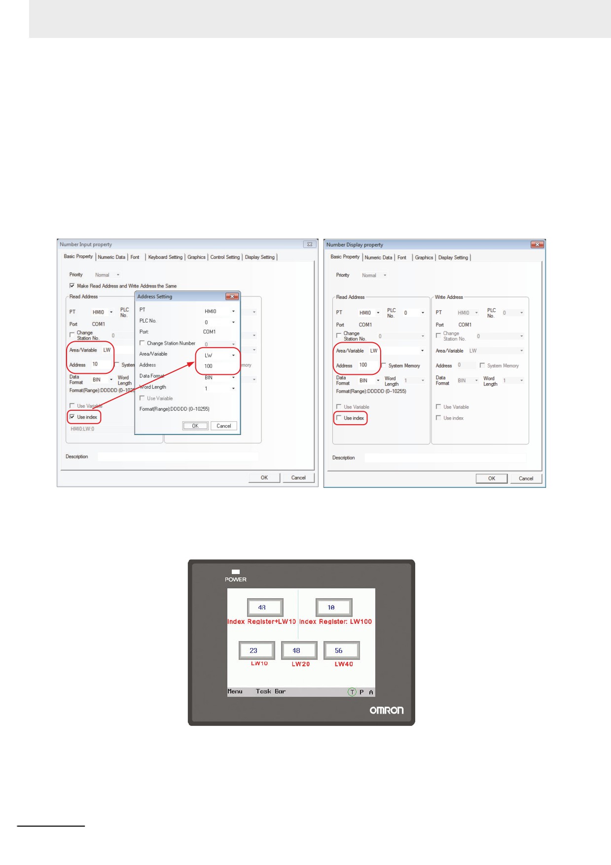
Index memory realizes the convenient address operation for the user. You can modify the I/O
address of the memory during the machine operation without modifying the edit screen. When
the index memory is selected for the component, the new I/O address of this component = the
value of the index memory + the original I/O address of this component.
For example:
(1) Create a project and place 5 Number Input components in it.
The settings of Number Input component NI0 are as in the lower left figure shown:
The settings of Number Input component NI1 are as in the lower right figure shown:
The settings of Number Input components NI2 to NI4 are the same as that of NI1, and their
addresses are LW10, LW20 and LW40 respectively.
(2) Perform the offline test. When the value of index memory is 10, the addresses of NI3 and
NI0 are the same.
3-412