OMRON NB-Designer OPERATION MANUAL (NB-series, 2020) - page 14
3 Functions of NB-Designer
7
Place another keyboard in the screen, and add some texts for decoration, then the project is
thoroughly completed.
3
After Save, Compile operations, perform the offline test for the project.
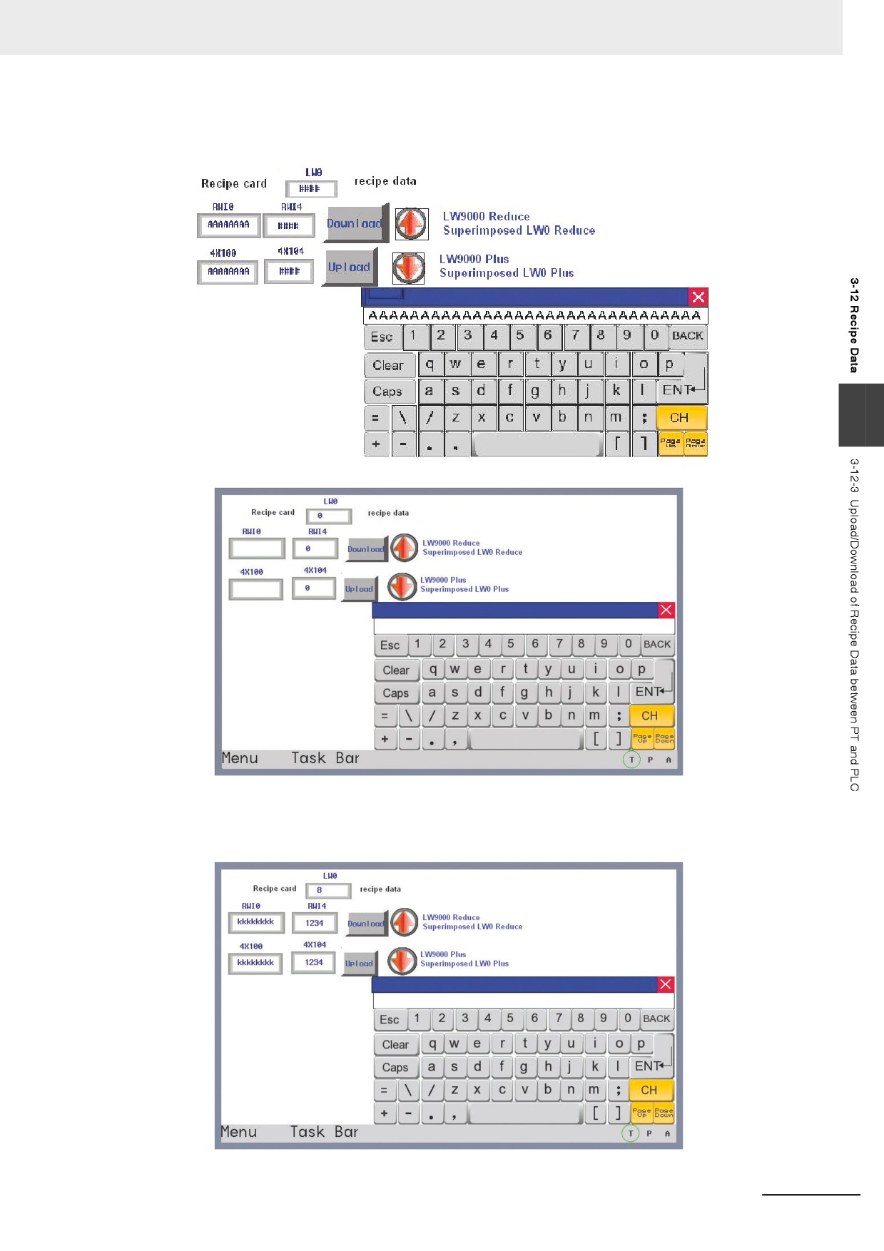
Input the 10 groups of recipe data into the recipe memory one by one, then switch to Group 8
of recipe data to change the name to “KKKKKKKK”, recipe data to “1234”, then you will see the
data in 4X100 and 4X10⁴ will become “KKKKKKKK” and “1234” respectively after the
Download button is pressed, as shown below:
3-353
3 Functions of NB-Designer
3-13 Security Level
Security Level is used to set the access authority for different users to enhance the security of the
project. Only the user having the high-level password can access the high-level screen, thus enhancing
the security of the project significantly.
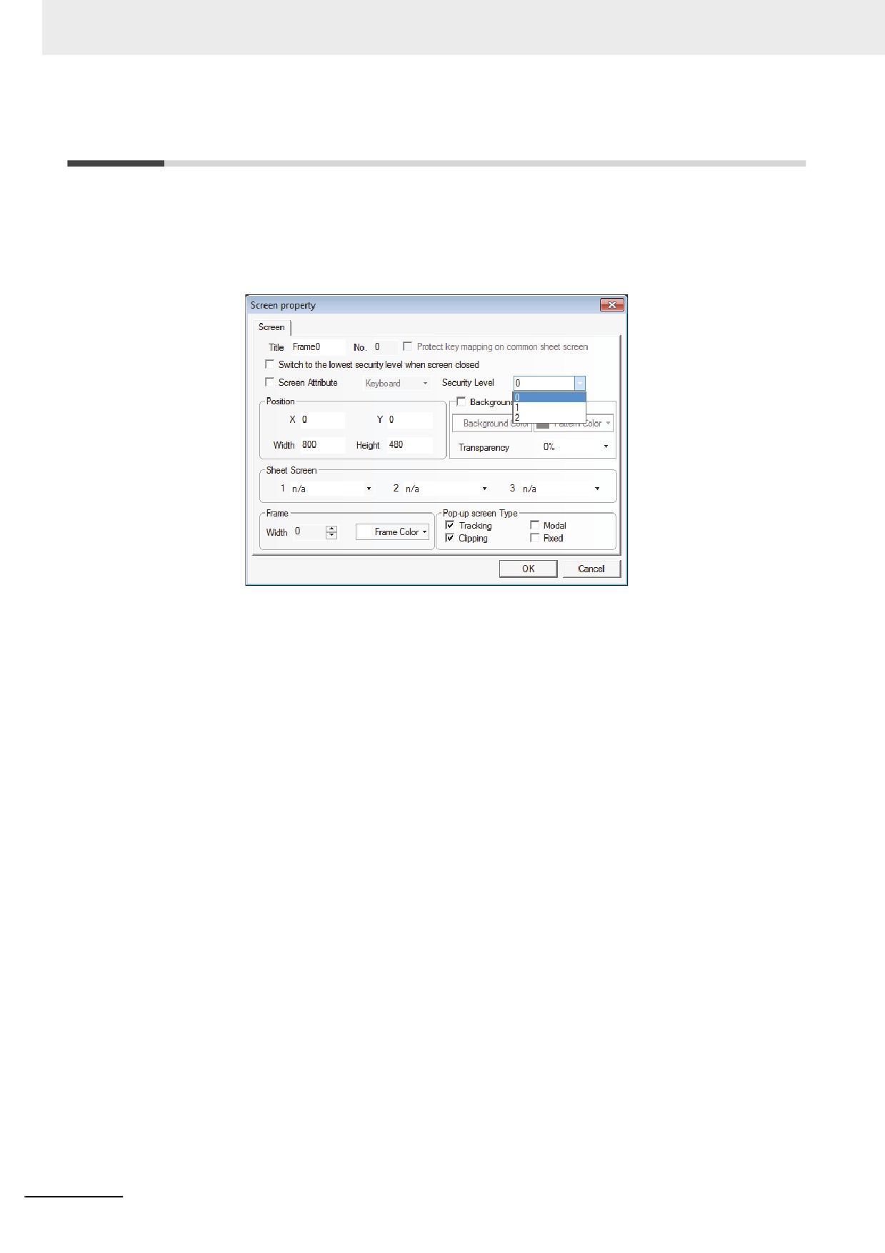
When setting Screen Property, we can see one column of “Security Level”. That’s to say, we can
specify the Security Level for any screen, as shown below:
The Security Level is only valid for the Base Screen. One project has 3 Security Levels, i.e. High
(2), Common (1) and Low (0) by default. The default security level is Low when creating a new screen.
You can set different passwords for each security level in the [PT Property]. The user with higher
security level can access the screen with the lower security level, while the user with the lower
security level can’t access the screen with the higher security level. Such kind of method is helpful
to the security management. For example, we can place the important switches into the screen with the
higher security level, so the user can’t access them after they enter this screen, and the contents can
be accessed only after the password for the higher security level is input.
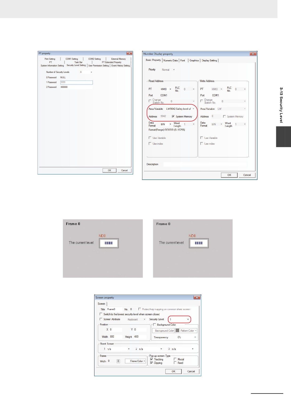
Here is an example about security level usage: Firstly, select [File] / [New], and double-click PT in the
Project Work Space, then set The number of Security Levels to 3, 1-level Password to 1111 and 2-level
Password to 888888 in Security Levels Setting tab of PT Property dialog box, as shown below:
3-354
3 Functions of NB-Designer
3
LW9042 reserved by the system is used to indicate the security level of the current Base
Screen. Create one Number Display component and place it into Frame 0 to display the current
security level, as shown below.
The project is shown as the lower left graphics and the effect is as shown in the lower right graphics
after Save, Compile and Offline test operations are done.
Because no password is input, the security level at initial state should be 0. Then specify the security
level to Common (1) in Screen Property of Frame 10 as below.
3-355
3 Functions of NB-Designer
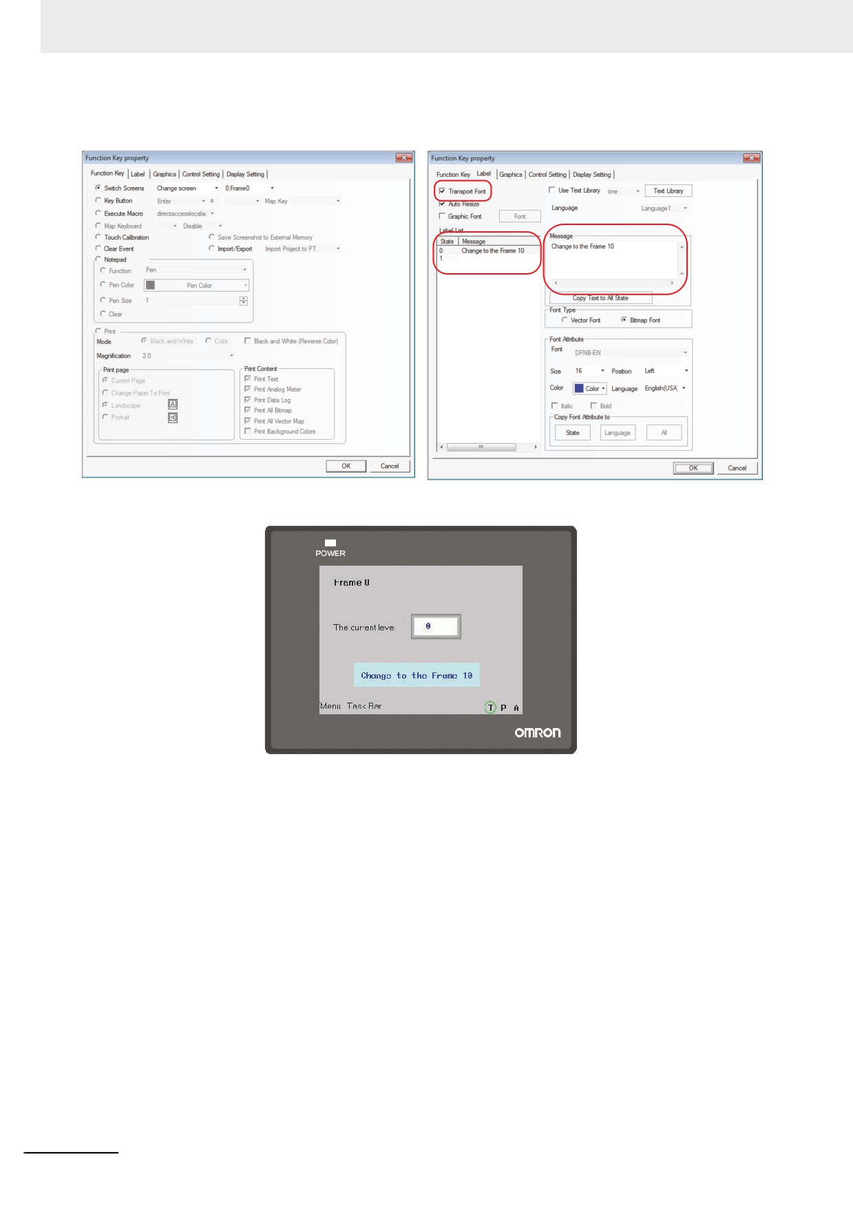
Create one Function Key in Frame 0 with the Properties as follows:
Perform Save, Compile and Offline test operations, and the effect is as shown below:
Pressing the Function Key button can’t switch to Frame 10. It is because the current security level is 0
while the security level of Frame 10 is 1, so the screen with the higher security level can’t be accessed
from the screen with the lower security level. We can access the higher security level screen only after
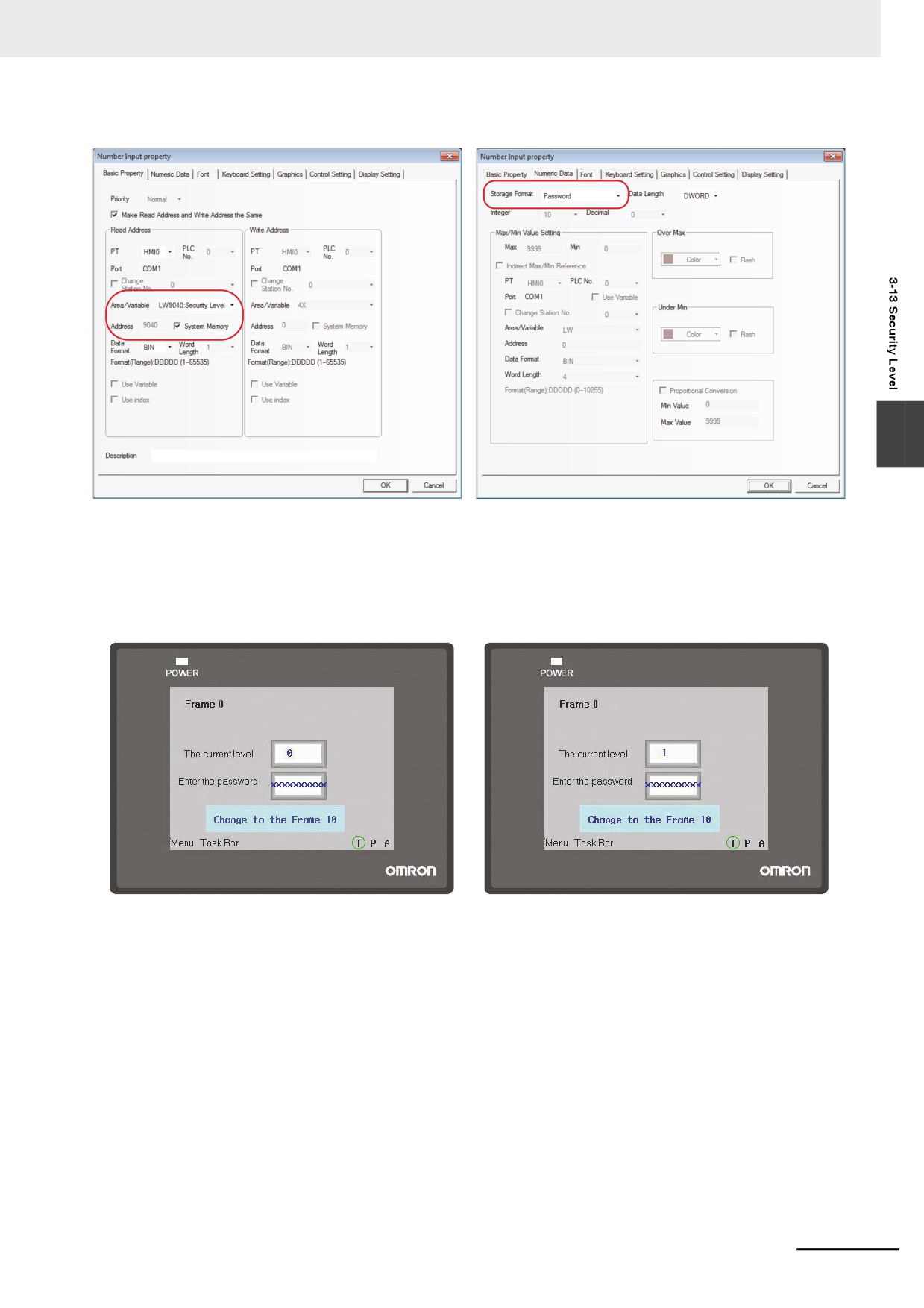
inputting the password corresponding to the higher security level. LW9040 to LW9041 reserved by
the system are used to input the security level passwords. Then place another Number Input
component with the Storage Format of “password” in Frame 0, as shown below:
3-356
3 Functions of NB-Designer
3
Note Since the system memories from LW9040 to LW9041 are used because of password input, the word length
should be set to 2 words.
After the Save, Compile and Offline test operations are performed; the effect is shown as the lower left
graphics: Pressing Change screen button is invalid for the current level is 0, and when the password of
1111 is input, the current security level becomes 1, as shown below:
3-357
3 Functions of NB-Designer
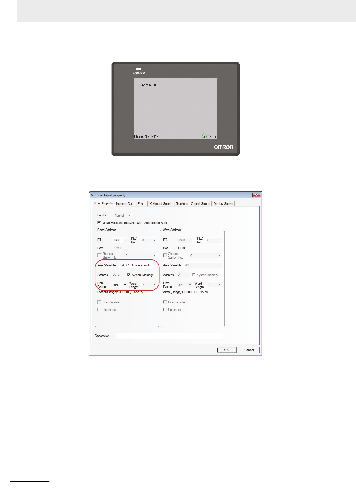
Now the current security level has become 1, the screen will switch to Frame 10 successfully when the
Change screen button is pressed, as shown below:
When the current security level is High, how to switch to Low level? LW9043 reserved by the system
is used to perform the switching from the higher level to lower level. And the switching from
lower level to higher level is impossible. Place one Number Input component in Frame 0, as shown
below:
3-358
3 Functions of NB-Designer
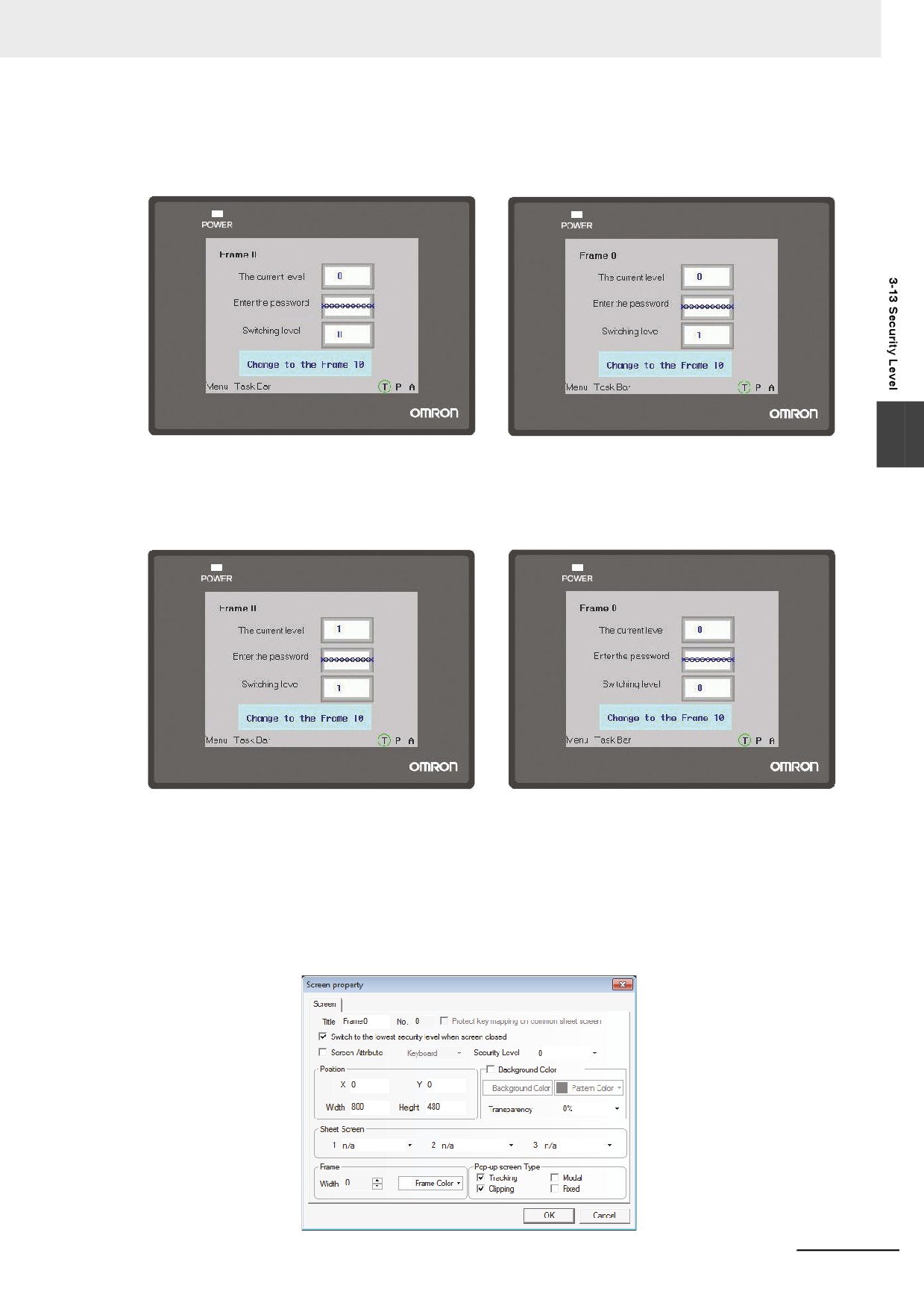
After the Save, Compile and Offline test operations are performed, the state is shown as below. After 1
is input at Switching Level, the current security level will not become 1 because the switching from
lower level to higher level is impossible, as the lower right graphics shows.
3
Then input the password 1111 to make the current security level become 1, as the lower left graphics
shows. At this time, pressing the Function Key button can realize the switching to Frame 10. But if 0 is
input at Switching Level, the current security level will be switched to 0, then the switching to Frame 10
will be impossible, as the lower right graphics shows.
Designing the project by using the level password properly and giving the users permission with
different level each allow the security of application enhanced.
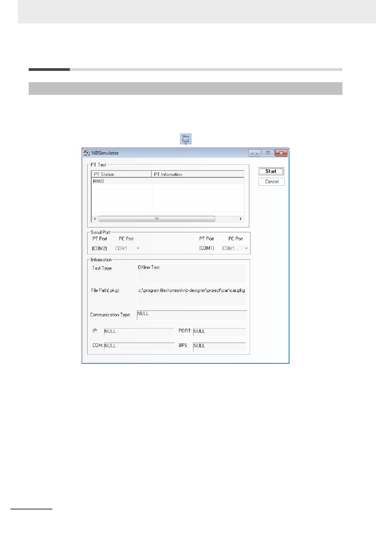
z Switching to the lowest security level when screen closed
If the security level is set for one screen to realize the following function: the password will be
cleared automatically when the screen is closed, and the password needs to be input again when
the screen is entered again. The security level will become 0 every time the screen is closed. The
settings are as shown below:
3-359
3 Functions of NB-Designer
3-14 Test
3-14-1
Offline test
NB-Designer supports the offline test function. Since the users can review the operation of the screen
data on creation without downloading the screen data to PT, the Offline Test can improve efficiency of
the screen creating.
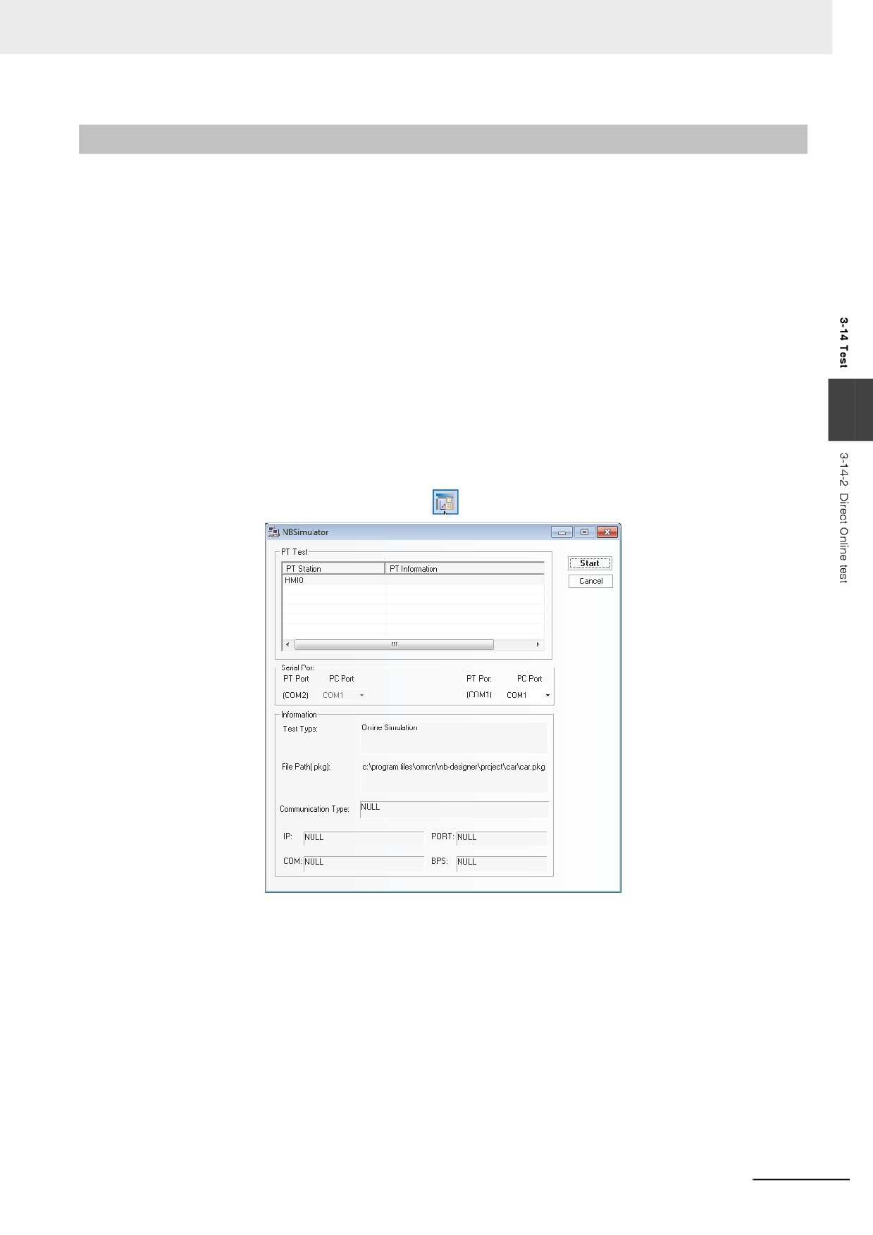
Select [Offline test] in [Tools] menu or press
icon, then the following dialog box will pop up:
Click the “Start” button after selecting the PT to be simulated, then you will see the offline test window.
3-360
3 Functions of NB-Designer
3-14-2
Direct Online test
NB-Designer supports online test operation. The online test provides the result which is equivalent with
the operation executed after downloading to PT and it allows to test directly on PC. Using the online
test during debugging can save a lot of time taken by the repeated downloading. The online test is
classified into direct online test and indirect online test, which are described as follows:
Direct online test is a test method that directly connects the PLC with the serial port of PC to test the
operation. Obtaining the dynamic PLC data without need to connect the PT is its advantage but the
communication between the PC and the PLC can support only RS-232 communications. During
debugging of PLC with RS-485 port, the adaptor that can convert RS-232 to RS-485/422 must be used.
Note 1
The test time of direct online test is 15 minutes. When 15 minutes is exceeded, the following prompt infor-
mation “The test time is exceeded, please perform the test again.” will appear. Then, the window of the
test will be closed automatically.
2
The direct online test can be done only through the RS-232 communication method.
3
The wiring method of direct online test is the direct connection of the PLC programming cable with the
3
serial port of PC.
4
It does not support the direct connection with the PLC of Ethernet connection type.
5
It does not support the direct online test with the other PLC than that manufactured by OMRON.
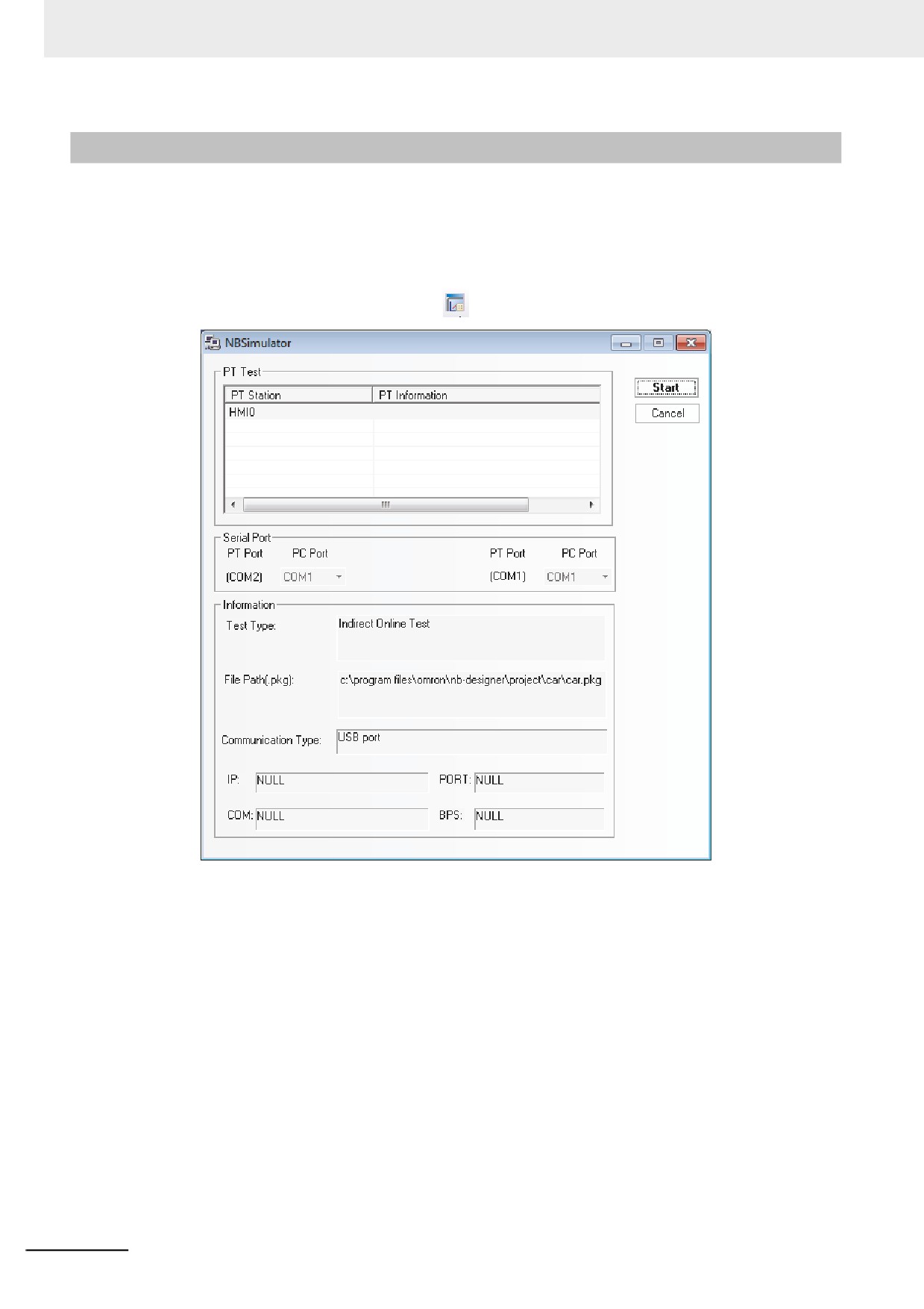
After the screen data is compiled, press the
button, then the following dialog box will pop up:
Select the PT No. to be tested and the COM No. of PC to be connected to the PLC, then click the
“Start” button to start the direct online test.
3-361
3 Functions of NB-Designer
3-14-3
Indirect Online test
The indirect online test is a method to obtain the data from the PLC through the PT and to test the
operations of PT. The indirect online test can obtain the data from the PLC dynamically, and the
operating environment is the same as that after the downloading except that the inconvenience of
downloading each time is avoided, thus it is quick and convenient, but it can’t be used independently
without the PT.
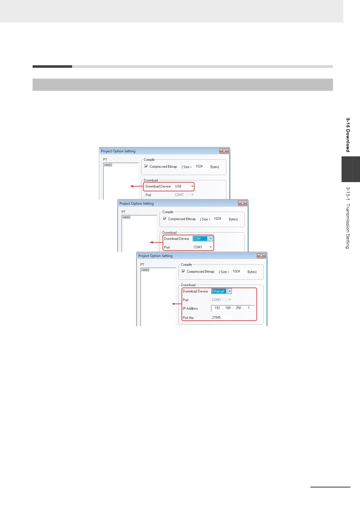
After the screen data is compiled, press the
button, then the following dialog box will pop up:
Select the PT to be tested, and click the “Start” button to start the test. NB Unit performs the indirect
online test through the USB, Ethernet or serial port.
Caution It does not support the indirect online test with the other PLC than that manufactured by OMRON.
3-362
3 Functions of NB-Designer
3-15 Download
3-15-1
Transmission Setting
After the project is edited, it can be downloaded to the PT to perform the actual operations. NB-
Designer provides 3 download methods, i.e. USB, serial port, and Ethernet (The Ethernet is only
applicable to NB
-TW01B.). Before the upload and download, you must set the communication
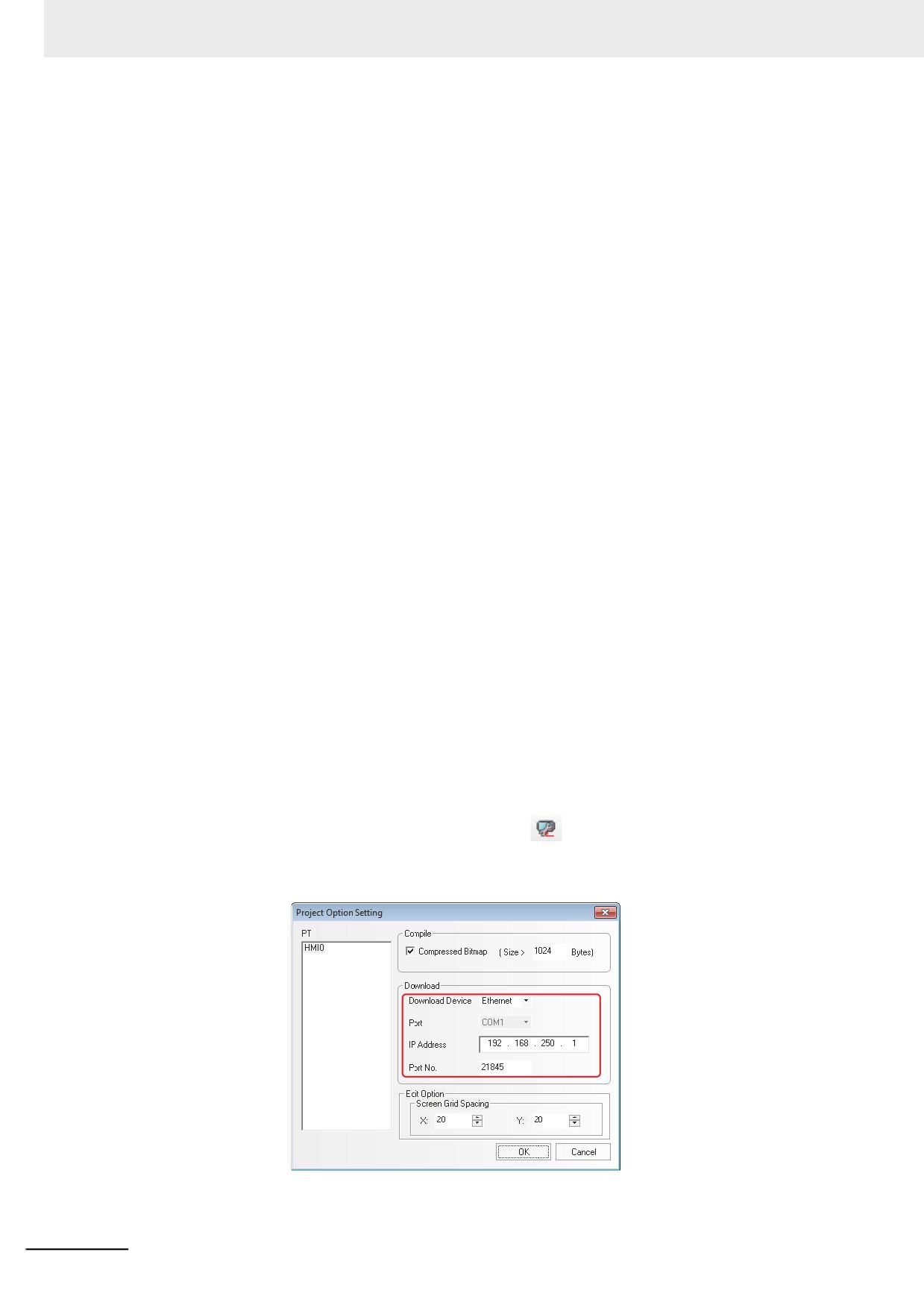
parameters firstly. You can select [Tools]-[Transmission Setting] menu to set the communication
parameters. After the [Project Option Setting] dialog box pops up, click the [Download Device] drop-
down list and select the required download way.
3
Download
via USB
Download via serial
port - used to select
the correct PC
Serial No.
Download via
Ethernet - used to
set the current IP
Address and Port
No. of PT
3-363
3 Functions of NB-Designer
1. USB
When using the USB to perform download for the first time, you should install the driver manually.
For the installation of the driver, please refer to 2-4 Installation of USB Driver for NB (Page 2-5).
When you use USB, you just need to select “USB” as download device and click the “OK” button to
start the download.
Compressed Bitmap: When this size is larger than the specified size, compress way will be used to
perform the compilation and download, thus saving a lot of space. Compressed Bitmap is checked
by default.
Note1
Checking Compressed Bitmap can reduce the size of the edited project.
2
Removing the check in the Compressed Bitmap option allows the switching speed of PT faster.
3
In order to ensure the PT with a faster communication speed during the operation, it is recommended
not to use too many bitmaps during the project editing.
4
Use less raster fonts as far as possible. The raster fonts occupy the same size as the normal graphics.
5
When the “Enable Printer Function” option is checked in the System Setting Mode, the USB Slave port
can be used only for printing function rather than the download function in User Project Mode. For
details, refer to Section 7 PictBridge Printing (Page 7-1) in NB-Designer Operation Manual.
2.Serial Port
Note The download through the serial port is slower for the edited project being too large, therefore it is not
recommended to use the serial port.
3.Ethernet
z Precautions for download through Ethernet and setting methods of IP
address:
The IP address of PC and that of PT should locate in the same network segment with the first 3
parts being same and the last part not being overlapped. If the LAN is used, the IP address can’t be
modified to prevent the conflict with the other IP addresses in the network.
First, set the network IP address in the “Control Panel” for Windows to the same network segment
as that for PT Unit. The IP address of PT Unit can be checked from the PT in the System Setting
Mode (with the DIP switches SW1 and SW2 on the back side both set to ON).
Then, make various settings in the Project Option Setting dialog box:
In the NB-Designer, select “Ethernet” from the Download Device option in Project Option Setting
dialog box after clicking [Transmission Setting] option
in the [Tools] menu, and then set the IP
address to be same as that of PT Unit. At that time, the project created in NB-Designer can be
downloaded into the PT.
3-364
3 Functions of NB-Designer
Changing Network Setting of PT Unit:
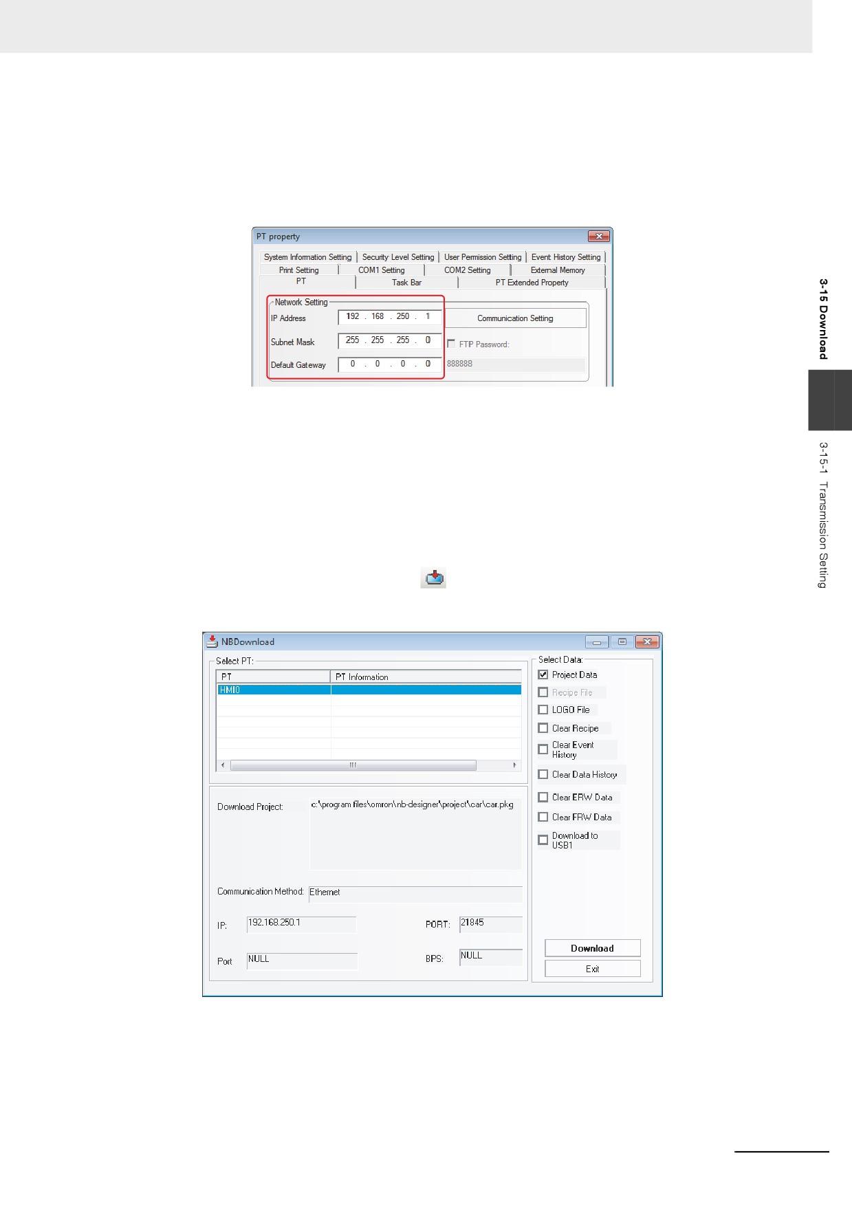
After confirming the download function, set the IP option in the [PT] tab in the [PT Property] dialog
box to the IP address and others, and then download it into PT after Compile operation is
performed. At that time, the IP address of PT is same as that set in the project. (If download through
Ethernet is performed again, please specify the modified IP address and port number in the Project
Option Setting dialog box.)
3
z Setting IP address in System Setting Mode:
For more details of Setting IP address in System Setting Mode, refer to the NB Series Setup Manual
(SBSA-550).
z Setting IP address by using [Set IP Address/Port] in NBManager:
For more details of Setting IP address by using [Set IP Address/Port] in NBManager, refer to 4-2-1
Communication Setting (Page 4-3).
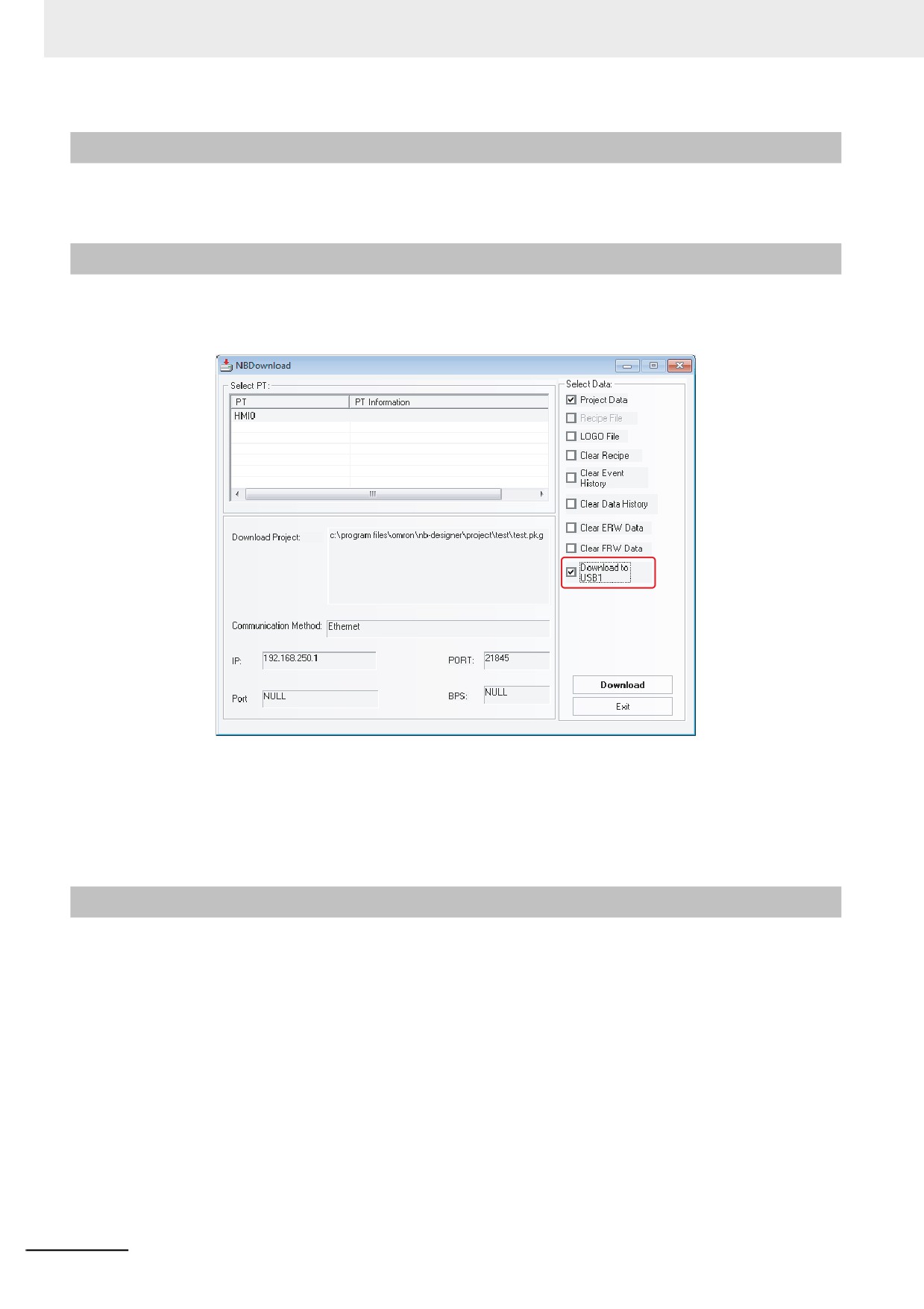
After the settings mentioned above, click
icon to download the screen data.
The download method is shown as below:
3-365
3 Functions of NB-Designer
3-15-2
Download via USB Memory
For more details of download via USB memory, refer to 3-2 Menus (Page 3-7) in NB-series Setup
Manual.
3-15-3
Download to USB1
When the project is too large, it can be directly downloaded to the external memory to operate. During
the download, check the [Download to USB1] in [Select Section] option in the [NBDownload] dialog
box, as shown below:
Click the [Download] button and then the project file will be downloaded to the external memory.
Note 1
If the project file is copied directly to the external memory without using Download, the project will not be
operated.
2
Do not remove the external memory during the operation of the NB. The project may not operate correctly.
3
Use the recommended device for the external memory.
3-15-4
Specification of Downloading Contents
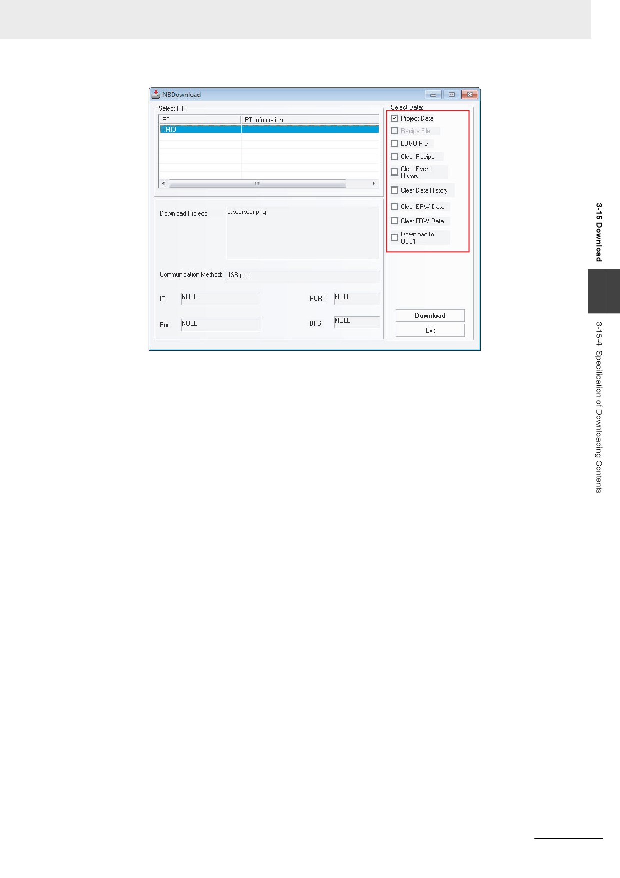
In the [NBDownload] dialog box, check the required contents in the [Select Section] option to download
the required files.
3-366
3 Functions of NB-Designer
3
Data File: Refers to the data information of all the components created by the user in PT screen. Only
after this option is checked, the downloaded project can work normally.
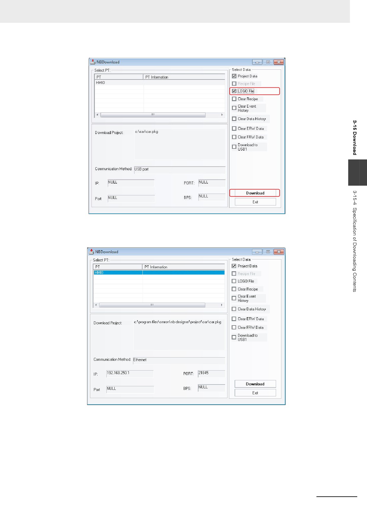
LOGO File: Download the initial screen (LOGO screen) displayed when starting PT. If the update of the
LOGO screen is needed, check the [LOGO file] check box and click [Download] to
download the screen.
3-367
3 Functions of NB-Designer
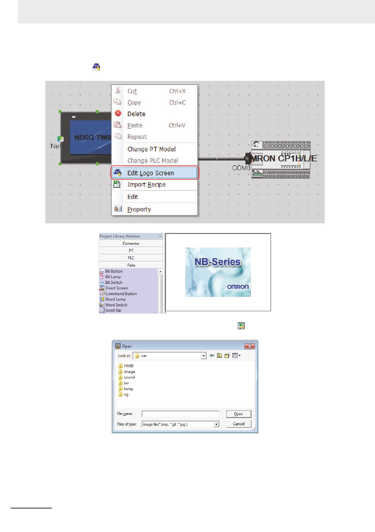
z Editing LOGO Screen
Press the icon in the toolbar, or select and click the PT in the Project Work Space to display the
Edit Window as below.
You can apply the optional LOGO screen. And if you click the icon in the toolbar, the following
dialog box will appear:
Find the required LOGO graphic, and click it to open it.
3-368
3 Functions of NB-Designer
After the compilation, check “LOGO File” and then click the “Download” button.
3
After the download is completed, “Download succeed” will be displayed.
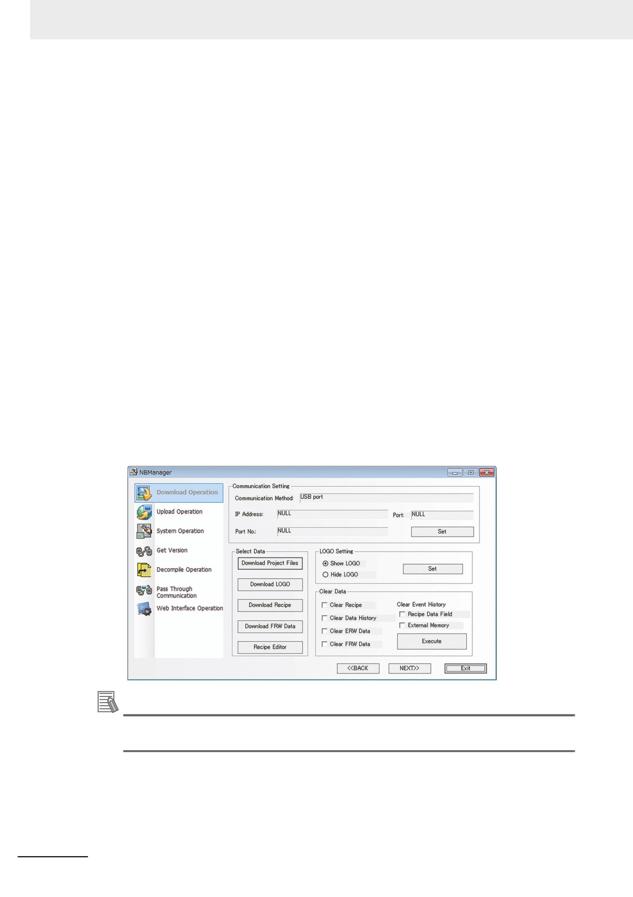
z Download Window
3-369
3 Functions of NB-Designer
Each function is described as follows:
1
Data File: It is used to download the current project.
2
Recipe File: The NB Series does not support this function. When downloading the Recipe
(.rcp), use NBManager.
3
LOGO File: Download the graphics used for LOGO screen. When the graphic is modified in
[LOGO Screen Edit], you need to check in the [LOGO file] option to download the modified
LOGO file to the PT.
4
Clear Recipe: If this check box is checked, the Recipe memory will be cleared to 0.
5
Clear Event History: Clears the saved events.
6
Clear Data History: Clears the saved sampling data.
7
Clear ERW Data: Clears the data in the ERW.
8
Clear FRW Data: Clears the data in the FRW.
9
Download to USB1: Download the project file to the external memory inserted to NB unit
(USB1). For the details of download to USB1, refer to 3-15-3 Download to USB1 (Page 3-366).
You can also select whether to clear the recipe data, FRW data, ERW data, data history, or event
history by using the Download Operate in NBManager.
Additional Information
To download the screen data of a different version, download the Kernel from NB Manger as
required.
3-370
3 Functions of NB-Designer
3-16 Other Functions
1
Editing component function
For the Copy and Paste operations, if a component is copied in the same screen, the copied
component will be placed in the position deviated 10-pixel away the original position. If the
component is copied in different screen, the copied component will be placed in the position of
the original position.
If multiple components are operated by the functions such as “Arrange Width”, “Arrange
Height”, and “Arrange Size”, the specific operation process is as follows: Select one
component as the reference, then perform “Width”, “Height”, or “Size” modifications. (If you use
the “Shift” key to select, then the component firstly selected should be as the reference, while
the component at the leftmost should be used as the reference during the selection made by
dragging the mouse. The selected mark for the reference is indicated by the solid rectangle,
3
while the selected mark for the other components is indicated by the hollow rectangle.)
2
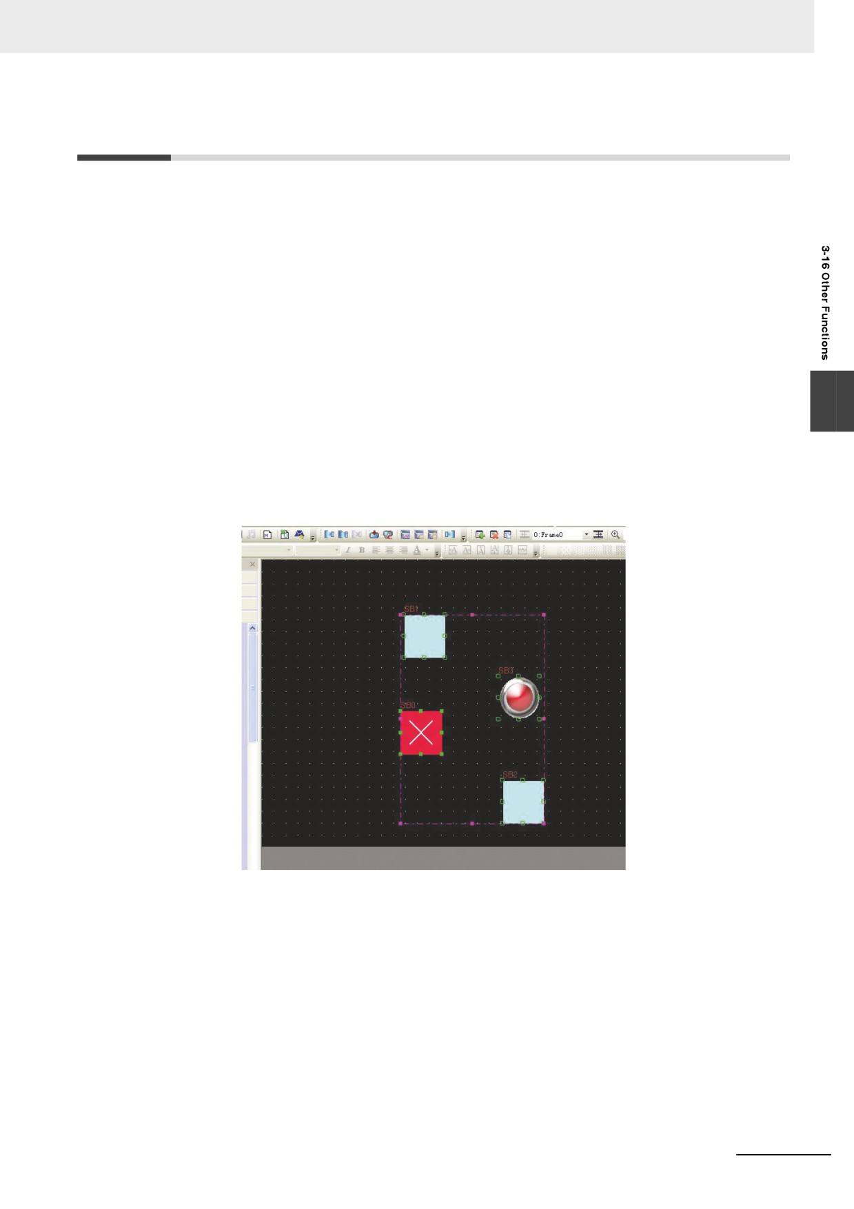
Proportionally zoom multiple components simultaneously
When the multiple components in the editing screen are selected together, selected area will
appear, and the user resize the multiple components simultaneously dragging by mouse each
point on the corners.
Resize the multiple components simultaneously dragging by mouse each point on the corners.
Above, the selected area is pink.
3-371
3 Functions of NB-Designer
3
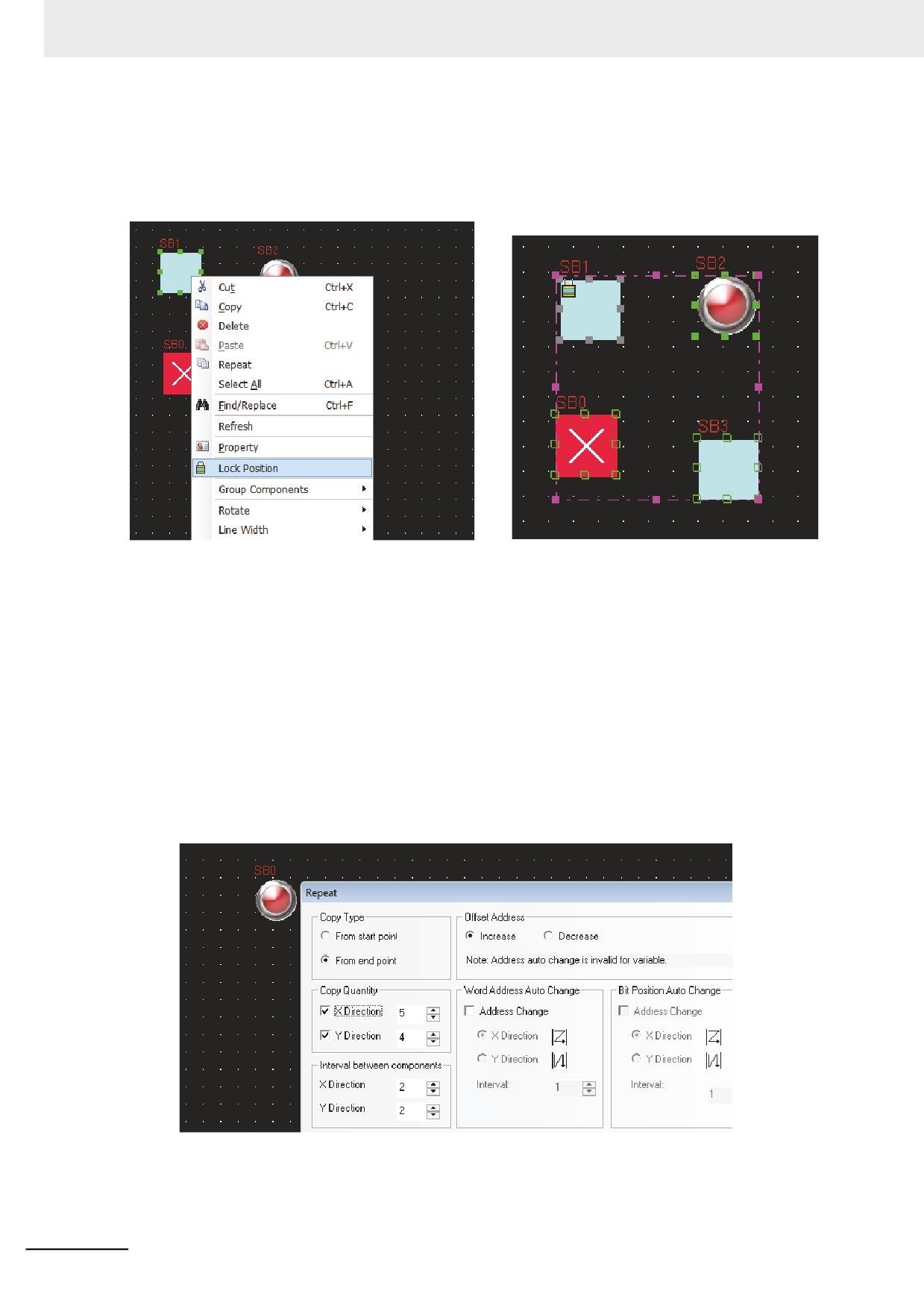
Lock Component
NB-Designer provides one function of “Lock Position” as shown below. Right-click the
component and select the “Lock Position”, and the effect is as shown below.
When the user selects the multiple components including the locked component to perform the
operation of movement etc, this locked component will have no response to this operation.
Please note that there will be one lock-shape mark on its original icon, as shown above.
4
Multiple Copy of Component
Single Copy: When the user selects one component to perform single copy, he just needs to
click the component while pressing the Ctrl key, which is equivalent to the operation of “Copy +
Paste”.
Repeat: It is intended for the multiple copy of a certain component, and the software can
automatically increase or decrease the component address and set the interval after the
component copy operation. Right-click the component to be copied, and select “Repeat” from
the Context menu, then the following dialog box will pop up. The user can make settings
according to the requirement.
3-372
3 Functions of NB-Designer
3
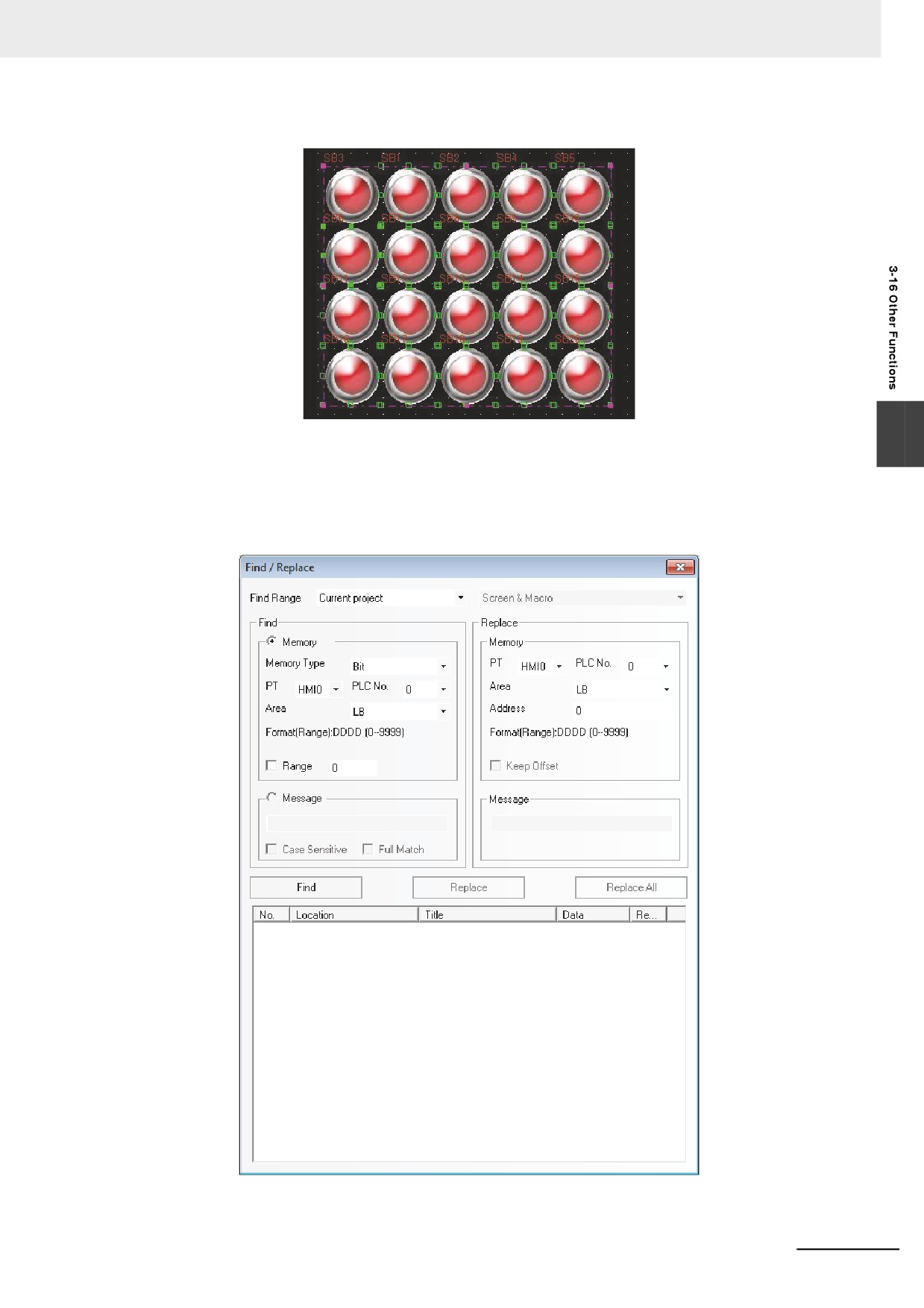
The effect of repeat is shown as above.
5
Find/Replace
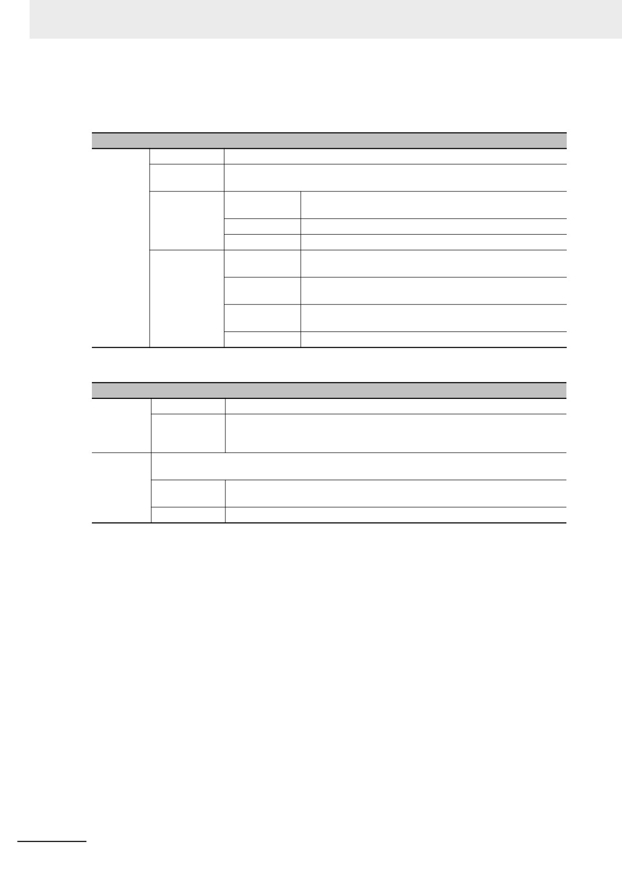
Select [Find/Replace] in the drop-down menu of the [Edit] menu or press the “Find/Replace”
icon, then the following dialog box will pop up.
3-373
3 Functions of NB-Designer
z Find Range
Refers to the content of the edit screen in NB-Designer to be searched, and it is classified into 4
kinds, as shown below.
Descriptions of Find Range
Find Range
Current Project
All the Screens, Macros and background database in PT will be searched.
Background
Only the background components such as Event Setting, Alarm Setting and Data
Database
Log etc. will be searched.
All PT
Screens and
All the Screens and Macros in the current project will be
Macros
searched.
All Screens
All the Screens in the current project will be searched.
All Macros
All the Macros in the current project will be searched.
Current PT
Screens and
All the Screens and Macros in the selected PT will be
Macros
researched.
All Screens
All the components in all the Screens in the selected PT will
be searched.
Current Screens
All the components in the current Screen in the selected PT
will be searched.
All Macros
Only all Macro in the current PT will be searched.
z Find
Descriptions of Find Type
memory
memory Type
It means to find the device with Bit type or Word type.
Area/Variable
It represents the device type and device address in the controller where the
search is performed. Checking “Range” means the search will be performed in
the set range of address.
Message
Not checking “Match Case” and “Full Match” means the judgment of the case of the characters
and the consistency in the whole text will not be done during the search.
Case Sensitive
It means the match of the case of the characters in the text to be searched is
required.
Full Match
It means the match of the text to be searched in the whole text is required.
z Replace
After this option is set, the area and address found according to the set conditions will be replaced
by the specified area and address.
“Keep Offset” in the Replace part will take effect once the “Range” in Find part is checked. If “Keep
Offset” is not checked, the replace address is the same; while if “Keep Offset” is checked, the
replace address is the consecutive address which will automatically deviate by making the set
replace address as the start address.
When the above parameters are set, if the “Find” button in the dialog box is clicked, the search of
address meeting the condition will be performed the screen locating in the Find Range. If the
component is found, then No., Location, Name and Data will be displayed in the bottom white box.
When the components displayed in the search result is double-clicked, the window will be switched
to the screen placed the matched components and Property dialog box will be displayed.
Clicking “Replace” or “Replace All” means the found component meeting the conditions will be
replaced by the component with the address type and address set in the “Replace” part.
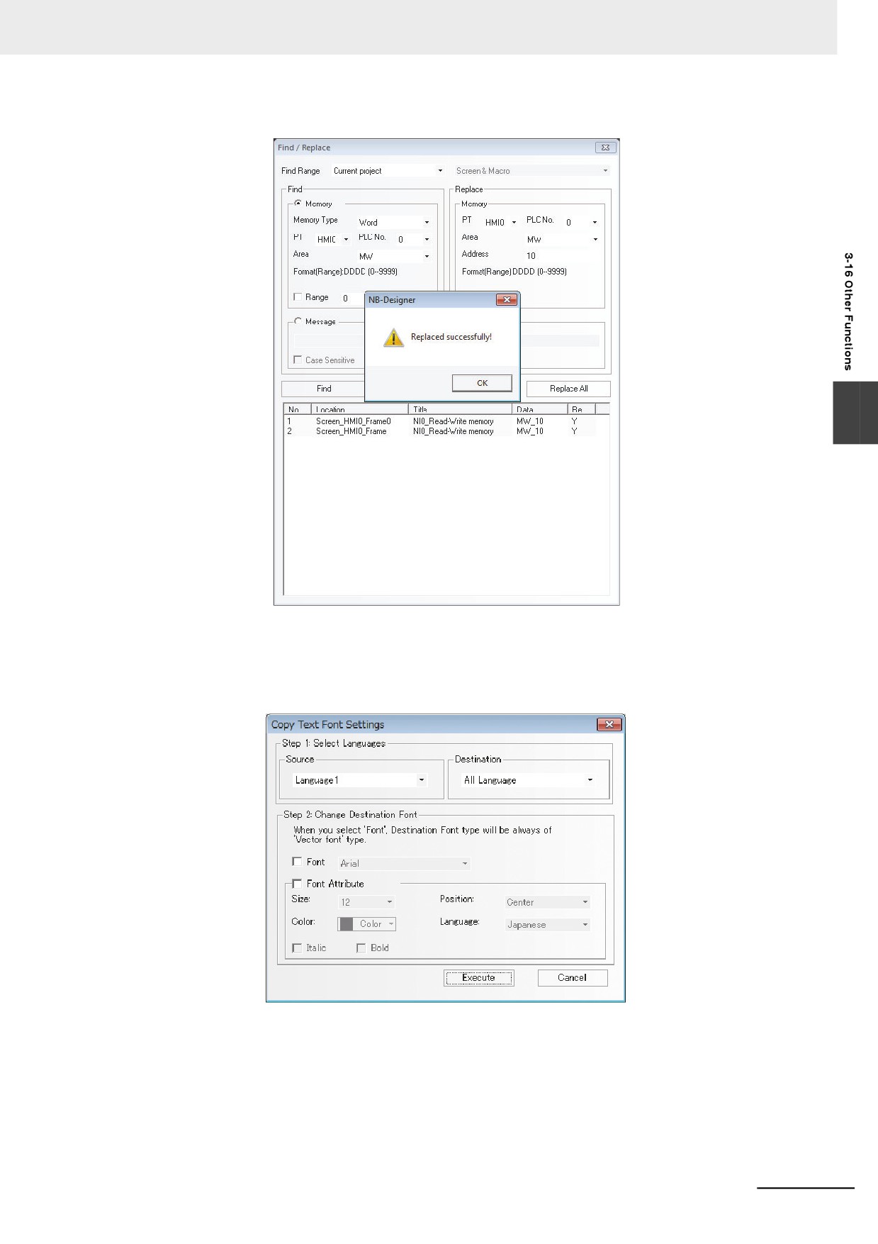
If the “Replace All” dialog box shown as below is clicked, the Write/Read Address of all component
which are specified to “MW0” in the current project, are replaced to “MW0”.
3-374
3 Functions of NB-Designer
3
6
Copy Text Font Settings
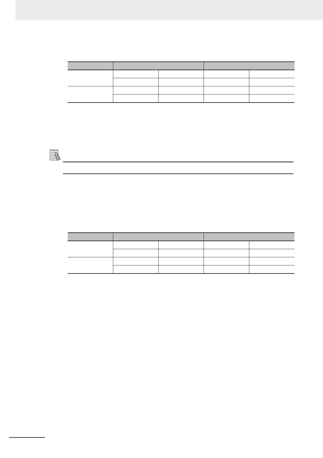
To change font settings of text parts where the Text Library is used, select [Edit] - [Copy text
font settings] in the Menu.
(1) Select a language you copy font setting.
Set the languages in [Source] and [Destination].
(2) Click Execute.
The settings will be copied from [Source] Language to [Destination] Language. It may take
a long time.
3-375
3 Functions of NB-Designer
Example) The following project has Text 1 and Text 2. Language 1 is set in [Source], and
Language 2 is set in [Destination].
Before
After
Text 1
Language 1 Font
DFNB-EN
Language 1 Font
DFNB-EN
Language 2 Font
DFNB-JP
Language 2 Font
DFNB-EN
Text 2
Language 1 Font
DFNB-JP
Language 1 Font
DFNB-JP
Language 2 Font
DFNB-EN
Language 2 Font
DFNB-JP
As for Text 1, DFNB-EN set as Language 1 will be copied to Language 2. Thus, both Language
1 and Language 2 will be DFNB-EN.
As for Text 2, DFNB-JP set as Language 1 will be copied to Language 2. Thus, both Language
1 and Language 2 will be DFNB-JP.
The font attributes (Size, Position, Color, Italic, and Bold) will be copied as well.
Additional Information
To change the settings regardless of Source settings, execute [Change Destination Font].
When check box in [Change Destination Font] is checked, after settings are copied, the
specified settings are overwritten.
To designate overwriting items, check the [Font] box and the [Font attribute] box.
Example) The following project has Text 1 and Text 2. The [Font] box is checked and DFHEI5
is set as the font.
Before
After
Text 1
Language 1 Font
DFNB-EN
Language 1 Font
DFNB-EN
Language 2 Font
DFNB-JP
Language 2 Font
DFHEI5
Text 2
Language 1 Font
DFNB-JP
Language 1 Font
DFNB-JP
Language 2 Font
DFNB-EN
Language 2 Font
DFHEI5
First, Language 1 set as Text 1 and Text 2 will be copied to Language 2. Next, Language 2
Font set in [Destination] will be overwritten to the designated font. As a result, Language 2 Font
on both Text 1 and Text 2 will be DFHEI5.
Note
Copying and overwriting will not be performed if the part becomes larger than the screen size due to the
change in the font size. Please specify an appropriate size.
3-376
3 Functions of NB-Designer
7
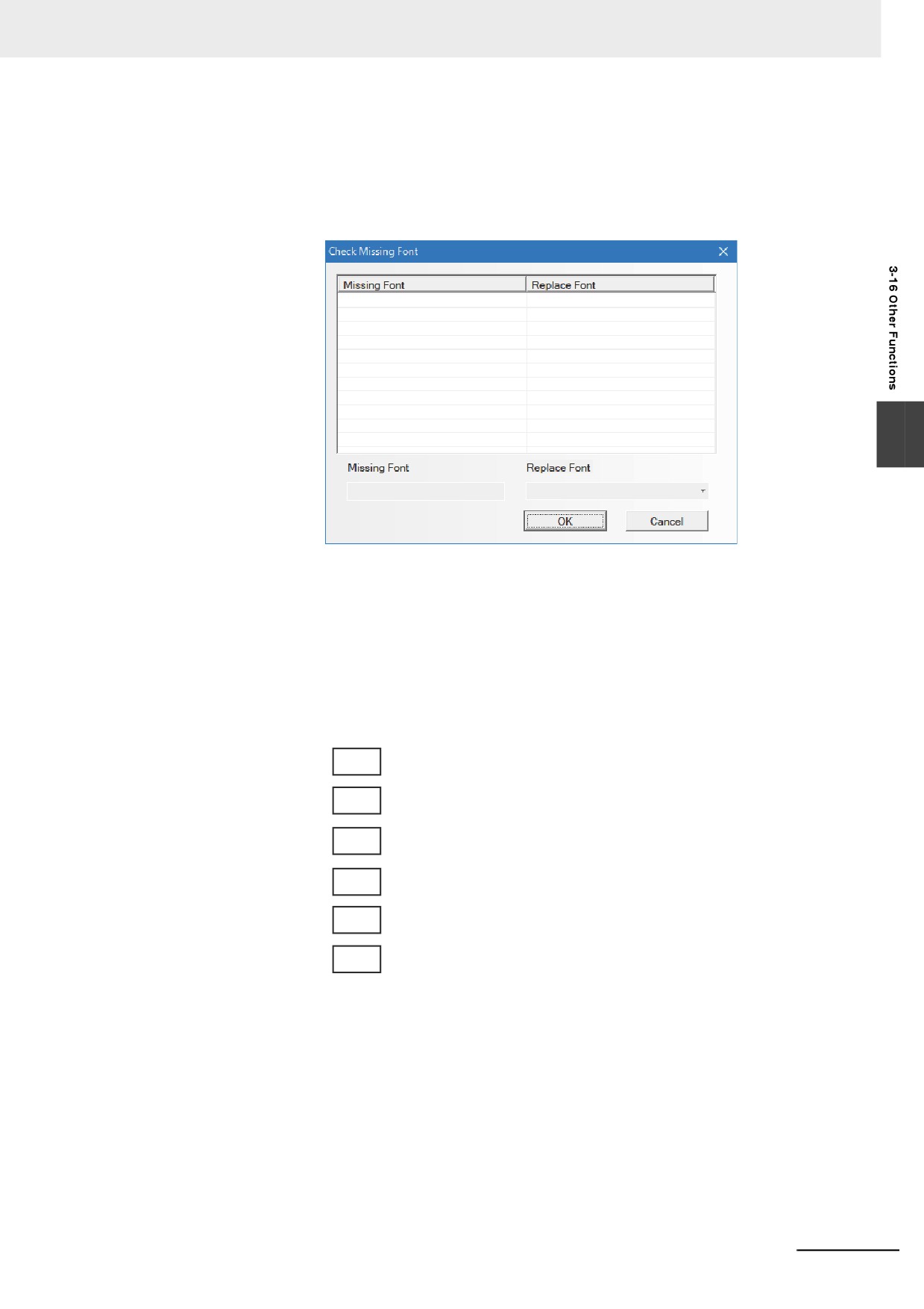
Check Missing Font
Click [Tool] - [Check Missing Font] in the menu to identify a font that not exist in your Windows
system and to replace it with the existing font collectively.
If your Windows system equips all the fonts, this function is not available.
3
8
About the overlay of component
Overlaying the multiple components together can realize many special functions. NB Unit
supports the overlay of multiple components. When these components are triggered, the
program will perform the corresponding operations according to the layer sequence, i.e. the
component on the top layer will be triggered firstly, then the component in the 2nd layer will be
triggered and so on. For example, if 6 Bit Switch components are overlaid together to control
the Y0 (top layer) to Y5 (bottom layer), then when these components are triggered, the NB Unit
will execute the functions in the following order:
First, execute the command Y0
Command execution Y1
Finally, command execution Y5
The control process is as follows: Y0 ON/OFF˘ Y1 ON/OFF (Step 2) ˘ Y2 ON/OFF (Step 3), ...,
˘ Y5 ON/OFF (Step 6).
3-377
3 Functions of NB-Designer
However, if the overlaid components include the function key of changing screen, the screen is
changed so that the other component behind the function key by are also unable to be
operated by the function. Therefore, the function key of the changing screen should be
arranged at the behind of all the component.
1st layer
Y0
First, execute the command Y0
2nd layer
Y1
Command execution Y1
3rd layer
Change Screen
Y2
4th layer
Y3
5th layer
Y4
Ignore all
6th layer
Y5
9
Pinyin Input Method
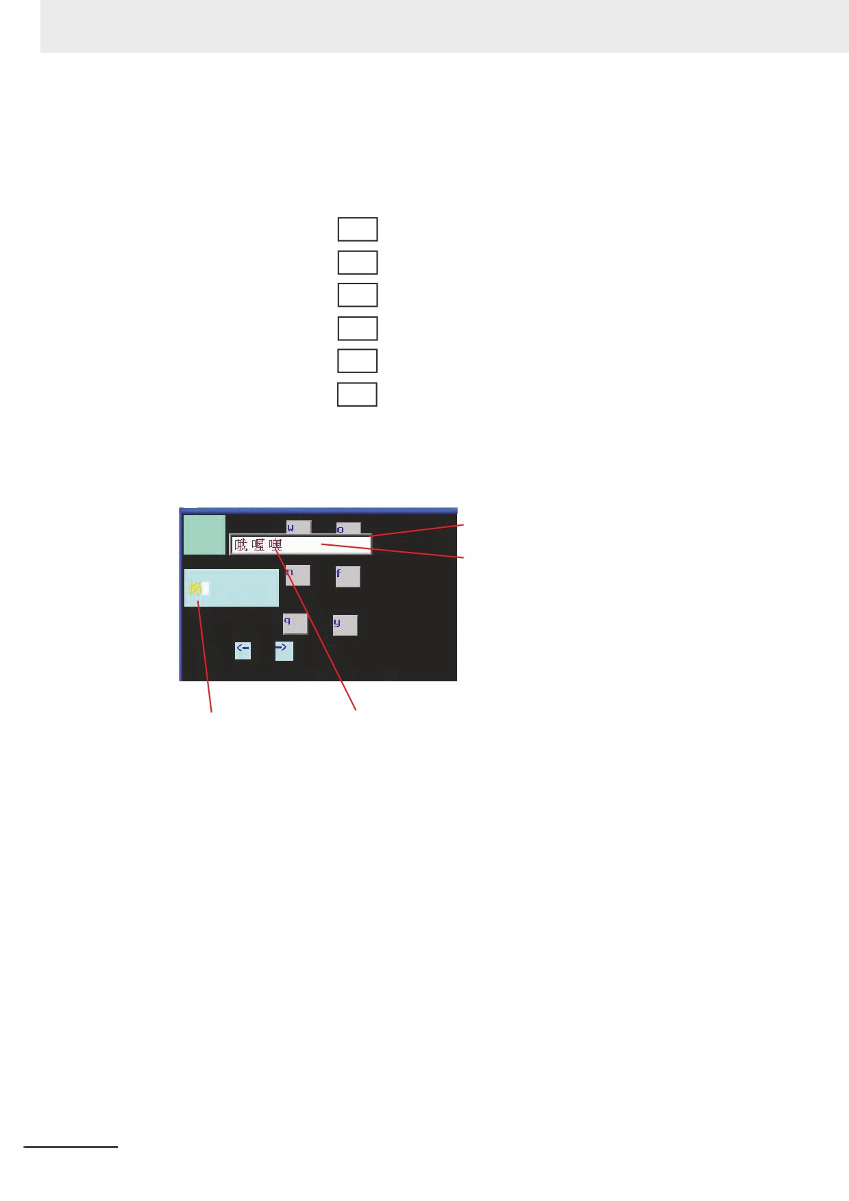
NB-Designer can be used to input common Chinese characters. Only Text Input component
and Not Book component support Pinyin Input method.
Chinese character
display screen
Touching a blank area
allows the component
moved.
Pinyin input text input
Touch characters, the
element as a carrier
completion of an operation
The memory related to the Pinyin input method is described as follows:
LB9100: Used for input method switching,
i.e. LB9100 = 1 for Pinyin input method, and LB9100 = 0 for English input method.
LW9150: Used for PageUp and PageDown operation to Chinese characters display screen.
Due to that 8 Chinese characters (max.) can be displayed in one Chinese character display
screen, the PageUp and PageDown functions are needed to display more Chinese characters.
The value of LW9150 is the No. of Chinese characters displayed in the current Chinese
character display screen. For example, it is assumed that the number of Chinese homophones
of Pinyin “wo” is M, when the value of LW9150 is N, then the Nth Chinese character and the
follow-up characters will be displayed in the Chinese character display screen.
LW9152 to LW9167: Used to display the Pinyin characters input currently.
3-378
3 Functions of NB-Designer
z
Usage:
Firstly, switch to the Pinyin input method through LB9100 when the input is triggered by the Text
Input component (or Note Book component), and input the Pinyin characters (displayed in LW9152
to LW9167 later) correctly, and touch the corresponding Chinese character from the several
Chinese characters displayed on the Chinese character display screen, then the process of
inputting Chinese character is completed.
Triggering the blank area of the Chinese character display screen can realize the movement of this
screen, which is similar to the screen console of the function key.
If the Pinyin needs to be modified during the input, the function keys of “Back Space” or “Clear” can
be used to realize this operation.
“Back Space” and “Clear” functions of Function Key is prior to the input Pinyin characters, i.e. when
the Pinyin characters are input currently, the object operated by the “Back Space” and “Clear”
function is the Pinyin characters instead of the other characters in the text input area.
Note
When the font size is 8, 24, 48, 72 or 96, the Pinyin input method is invalid.
3
10
LSB Type
LSB type is applicable to the Command Button component, Word Lamp component, and Word
Neon Lamp component. If the Bit Button component is operated, the text string to display in
neon lamp and others can be controlled.
LSB is the acronym of Least Significant Bit. This encoding type first converts the data in the
buffer to binary data, and then determines the current state of the component based on the
number of consecutive “0” at the least significant bits of the binary data.
[Example] Take an example of the data with word address to be displayed:
Number of
Hexadecimal
Decimal
Binary
consecutive “0” at
State Number
least significant bits
0000
0
0000 0000 0000 0000
16
16
0001
1
0000 0000 0000 0001
0
0
0002
2
0000 0000 0000 0010
1
1
0003
3
0000 0000 0000 0011
0
0
0004
4
0000 0000 0000 0100
2
2
0005
5
0000 0000 0000 0101
0
0
0006
6
0000 0000 0000 0110
1
1
0007
7
0000 0000 0000 0111
0
0
0008
8
0000 0000 0000 1000
3
3
…
…
…
…
…
0010
16
0000 0000 0001 0000
4
4
0020
32
0000 0000 0010 0000
5
5
0040
64
0000 0000 0100 0000
6
6
0080
128
0000 0000 1000 0000
7
7
0100
256
0000 0001 0000 0000
8
8
0200
512
0000 0010 0000 0000
9
9
0400
1024
0000 0100 0000 0000
10
10
0800
2048
0000 1000 0000 0000
11
11
1000
4096
0001 0000 0000 0000
12
12
2000
8192
0010 0000 0000 0000
13
13
4000
16384
0100 0000 0000 0000
14
14
8000
32768
1000 0000 0000 0000
15
15
…
…
…
…
…
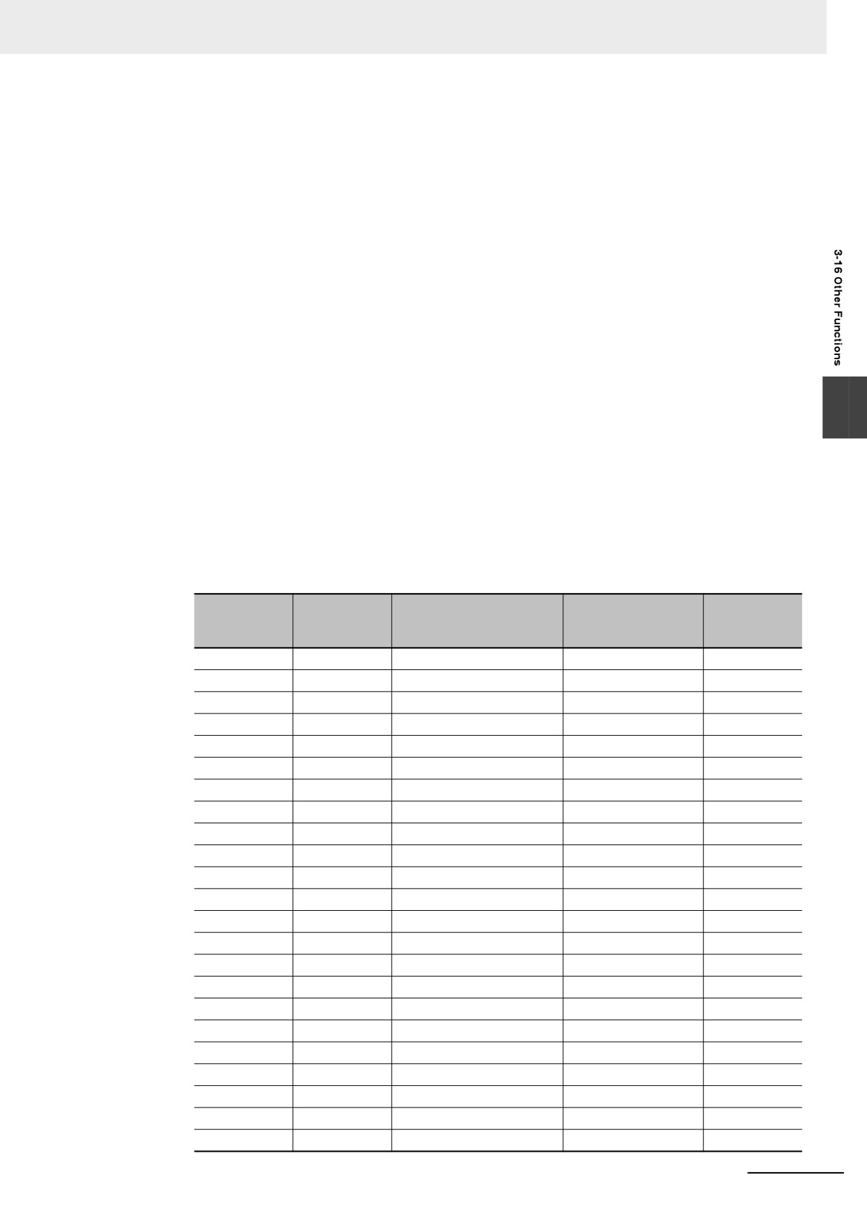
3-379
3 Functions of NB-Designer
11 Disconnected Host can be Masked of the Station No.
The disconnected Host can be masked with the communication error. If the settings are valid,
all the “PLC No Response” for the device behind can be masked.
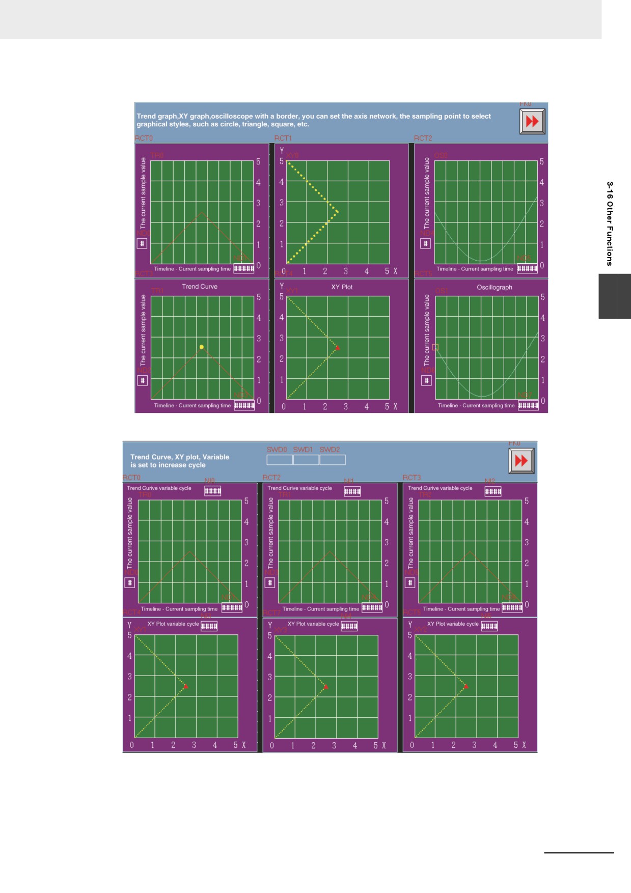
12 Data Log, XY Graph and Oscillograph
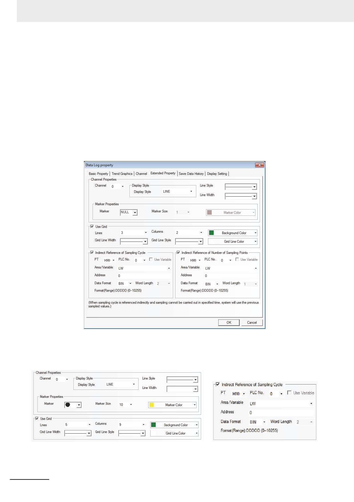
Data Log/XY Graph/Oscillograph components have extended Properties, as shown below:
(a) Border, Grid and Background Color etc.
(b) Display Type of sampling point.
(c) Sampling cycle can use the Indirect Reference.
(d) The style of XY Graph are scatter plot and shaded plot.
(e) Sampling points can use the Indirect Reference.
(f) The Data Log can be saved to the PT and external memory simultaneously.
When the sampling cycle and the sampling points are specified indirectly, if the value of the
reference address cannot be obtained, the value obtained previously can be used.
The extended properties of the data log are as follows:
3-380
3 Functions of NB-Designer
The effect of the screen is as shown below:
3
3-381
3 Functions of NB-Designer
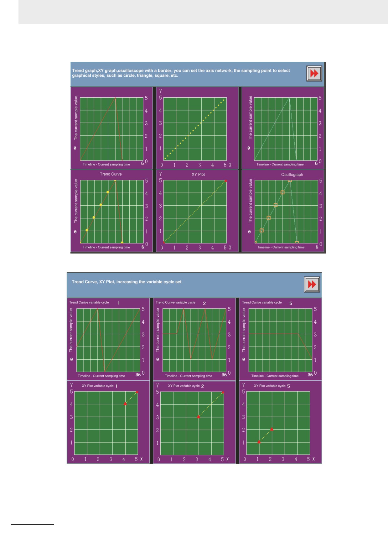
The effect of test is as shown below:
3-382