OMRON NB-Designer OPERATION MANUAL (NB-series, 2020) - page 12
3 Functions of NB-Designer
3
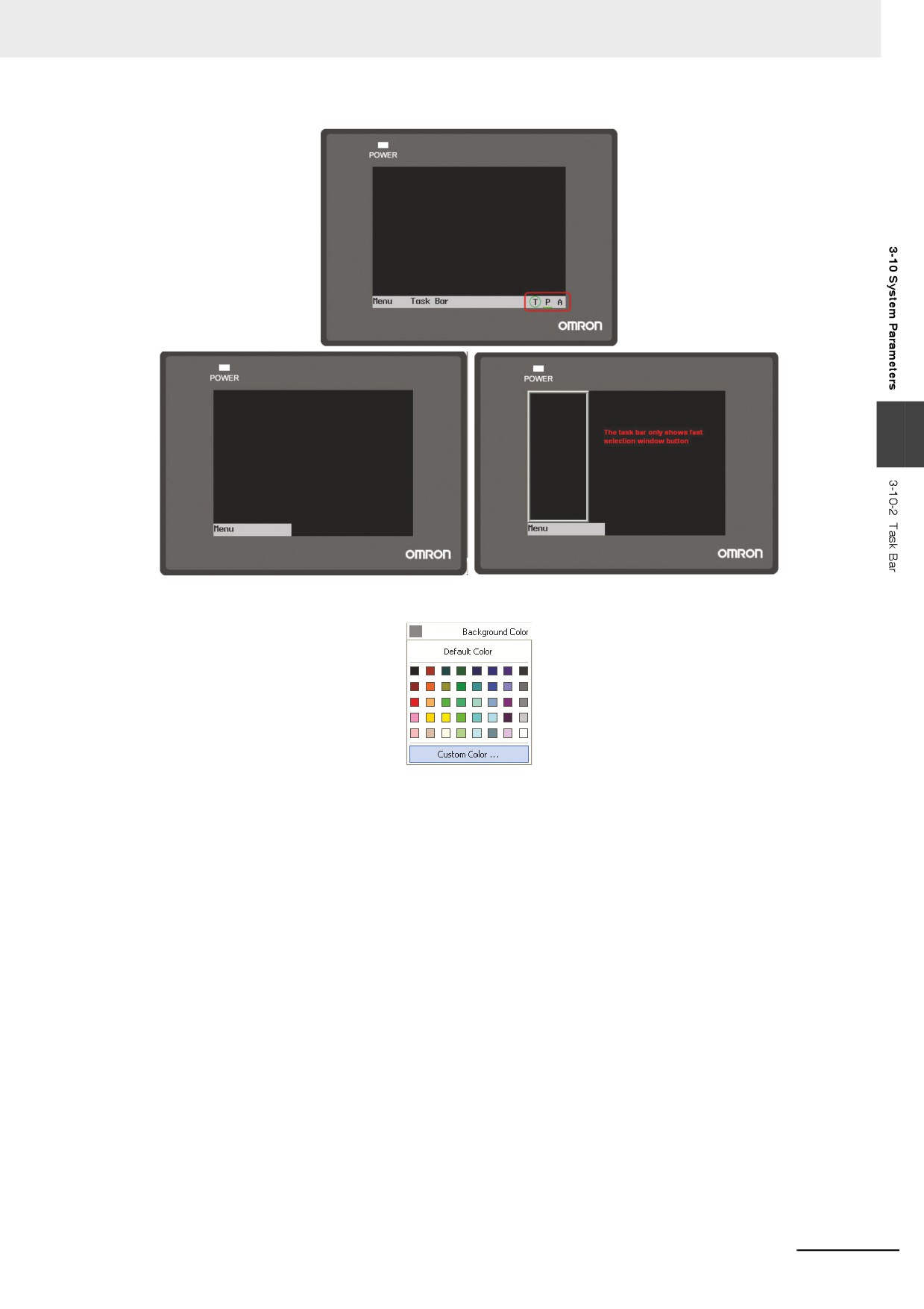
Background Color: Determines the background color of the task bar. You can select the following colors
at “Default Colors” or select “Custom Colors” to configure any colors you want.
Undefined Area Color: When you click the undefined area, i.e. the area outside of working area for touchable
components or without the components, the Touch Indicator will change colors.
CPU Indicator Color: Refers to the color of CPU Indicator.
Alarm Indicator Color: Refers to the color of Alarm Indicator.
Touch Indicator Frame Color: Refers to the box color of the Touch Indicator.
Touch Unable Area Color: Refers to the Touch Indicator color shown when the nonclient area is
touched (including when expected effect is not realized after the
component(s) being touched).
Touch Area Color: Refers to the Touch Indicator color shown when the client area is touched (including
when related action(s) is (are) performed after corresponding component(s) or Menu
Bar etc. being touched).
Menu Button/Task Bar Button: Input the texts which should be displayed in the Task Bar and in the
location which displays the Menu Screen of the Task Bar.
Button Position: Refers to the positions of the Menu Button and Task Bar Button, i.e. “Left” and “Right”. If you
select “Right”, the Menu Button and the Task Bar Button will be placed in the lower-right corner
of the screen. On the contrary, they will be placed in the lower-left corner of the screen.
Text Position: The text alignment in the Menu Button and the Task Bar Button includes “Left”, “Right”
and “Center”.
Button Size: Refers to the width and height of the area where the button locates.
Font Size: Refers to the font size of the texts in the Menu Button and the Task Bar Button.
3-293
3 Functions of NB-Designer
3-10-3
PT Extended Properties
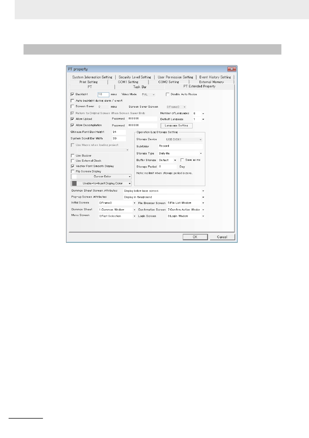
Backlight: How long (minute) the backlight will be closed when the screen is not touched.
Auto backlight during alarm/event: When it is checked, the backlight will automatically turn ON when
the alarm/event occurs.
Screen Saver: The duration until the screen saver is started after the inactivity.
Screen Saver Screen: After the screen. saver is checked, a certain screen can be selected as
Screensaver Screen.
Return to Original Screen when Screensavers Ends: When it is checked, the screen will return to the
Original Screen after the screensaver ends.
Allow Upload: Since the respects of the information disclosure, remove the check the check box when
prohibiting the upload.
Allow Decompilation: Allows the user to decompile and modify the PKG files generated by
configuration compilation after it is checked. For this function, a password
setting is required.
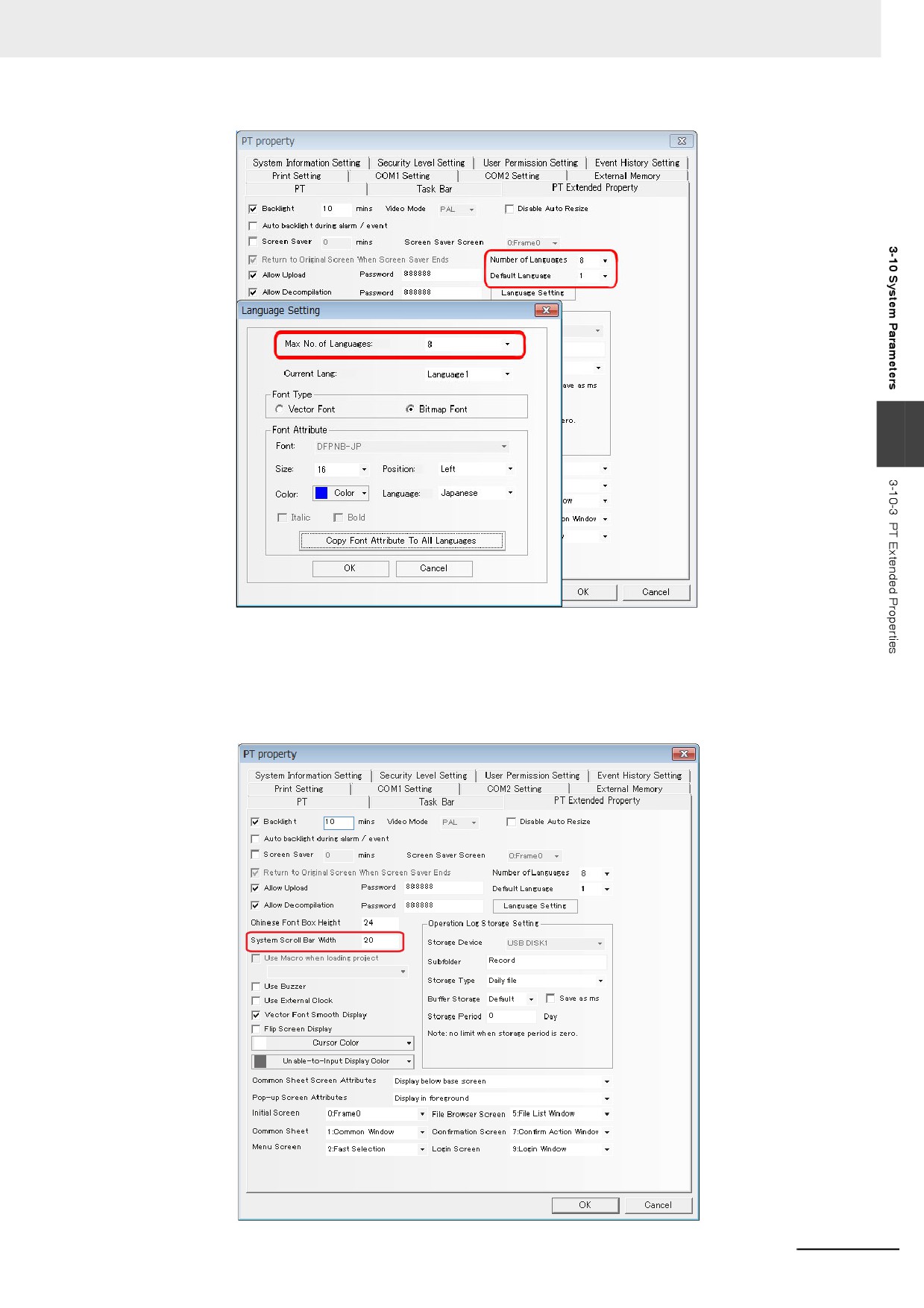
Number of Languages: Specify the number of the languages used in the project. The languages used
by the component of the PT is generally less than or equal to the maximum
language number. For example, the maximum language number is 7 and the
number of used languages is 5, the components in PT can only use 5 kinds of
languages. For the details, refer to 3-8-1 Text Library (Page 3-238).
Default Language: Refers to the default language when the project is opened originally.
3-294
3 Functions of NB-Designer
3
Disable Auto Resize: Temporarily disables the set Auto Resize function for all components in the
project data.
System Scroll Bar Width: Refers to the component with the scroll bar such as operation log
component. The width of the scroll bar can be set with this option and the
width range is from 20 to 120 pixel point. When the spacing is 4 (i.e. 20, 24,
28 and so on), the scroll bar can be displayed effectively.
3-295
3 Functions of NB-Designer
Use Macro when loading project: Refers to the Macro file run firstly when the unit starts processing
the project file after it starts.
Use Buzzer: When the component of the PT is pressed or the “Beep Function” is set for the Alarm or
the Event, check the check box.
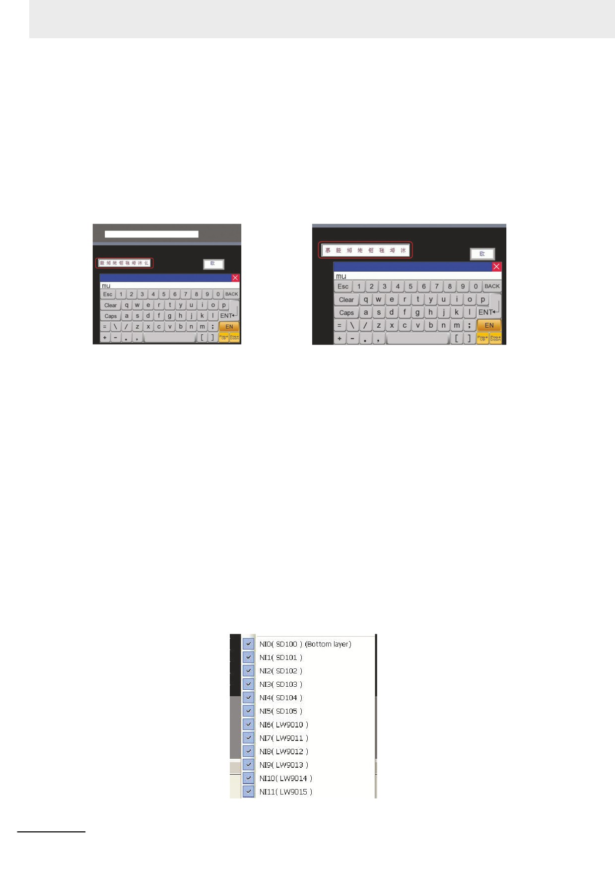
Chinese Font Box Height: Sets the height of text input box and the default value is 24.
When inputting the characters in Pinyin form, the Chinese font box height can be adjusted between 24
and 99 (pixel).
Perform the offline test and the effect is as shown below:
When the Chinese font box height is 24:
When the Chinese font box height is 34:
Chinese font box height can be adjusted
Use External Clock: After it is checked, the values in the memory of LW9010 to LW9017 are adopted
as the event occurrence time, and internal clock of the PT are not adopted.
Note Using this function needs to use Data Transmission component to transfer the data in the time memory of
PLC to LW9010-LW9017 periodically.
LW9010: Second
LW9011: Minute
LW9012: hour
LW9013: Date
LW9014: Month
LW9015: Year
LW9016: Week (unavailable)
LW9017: Millisecond
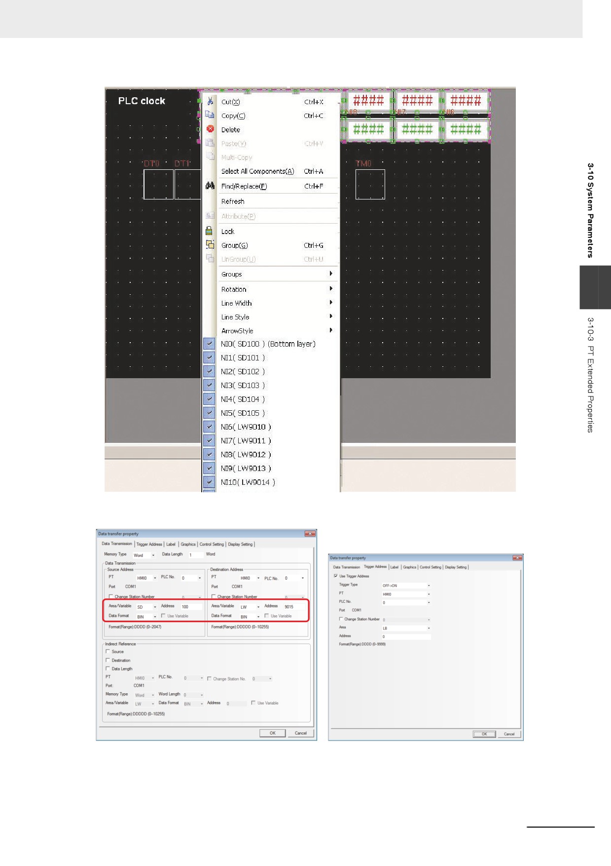
In the following example, we will use the Data Transmission component to transfer the values in the
time memory of PLC to LW9010~LW9017 periodically.
i.e. transfer SD100 to LW9015, SD101 to LW9014, SD102 to LW9013, SD103 to LW9012, SD104 to
LW9011 and SD105 to LW9010.
3-296
3 Functions of NB-Designer
3
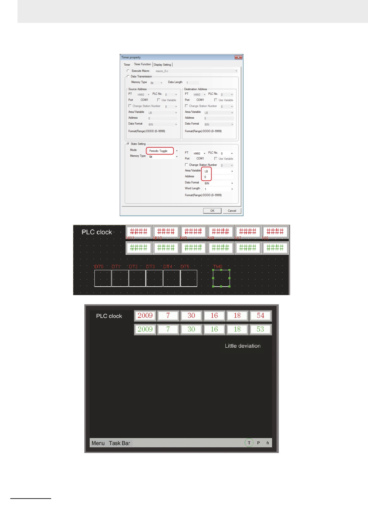
Because the order of the corresponding addresses is reversed, so it needs 6 Data Transmission
components and 1 Timer component.
3-297
3 Functions of NB-Designer
3-298
3 Functions of NB-Designer
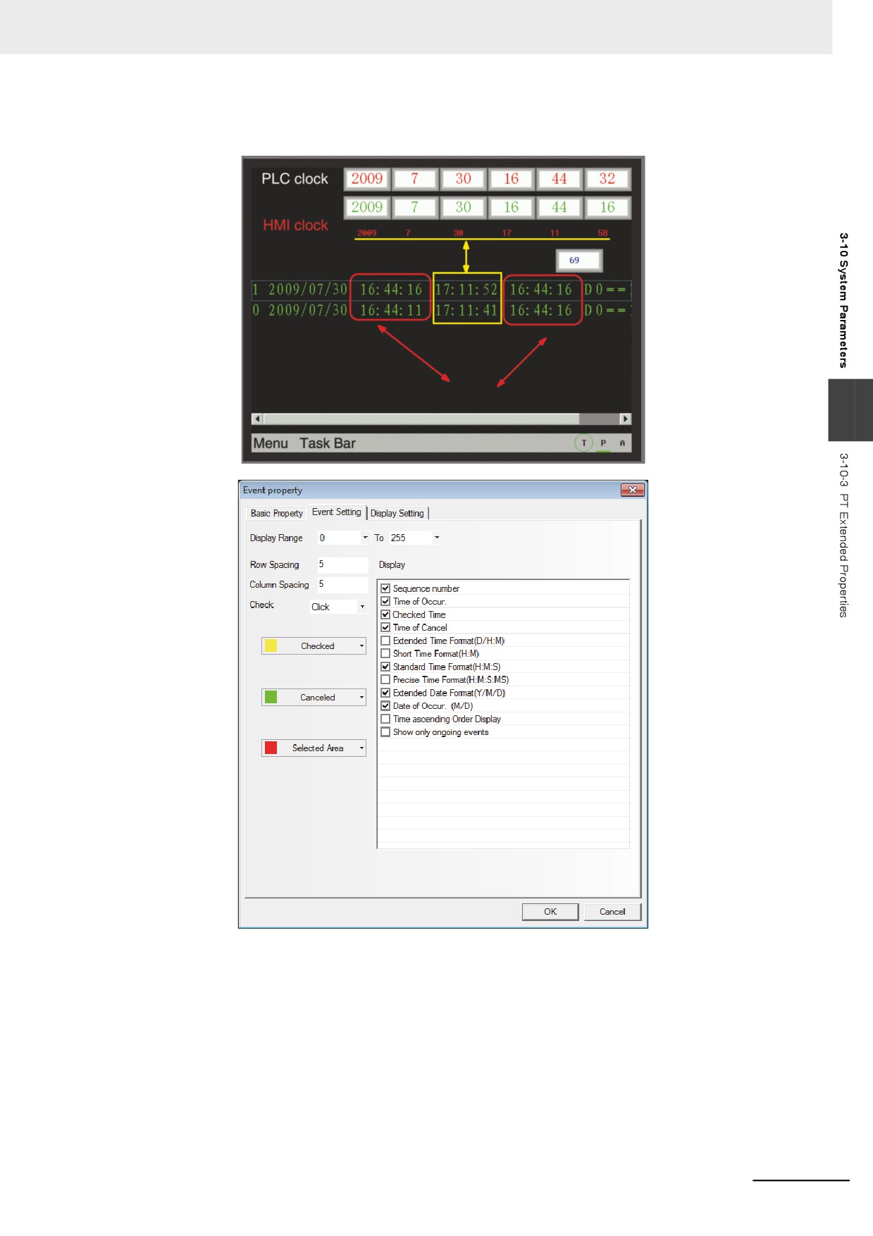
After creating a new Event Setting, place 1 Event component, then perform the indirect online test and
the effect is as shown below:
PLC time
3
“Checked Time” refers to the PT time, therefore we must pay attention to it when using this function.
And it’d better to use it after the time is adjusted well.
3-299
3 Functions of NB-Designer
Vector Font Smooth Display:
The characters can be made smooth, beautiful and no-alias by using “Vector Font Smooth Display”.
But using this function can increase the computations of the PT, and may affect the processing speed
of the PT with the slower speed of refreshing of the PT. Therefore, if the user doesn’t have the higher
requirements for the vector font display but have the requirements for the faster refreshing speed of the
PT, please do not check this option. The default is checking “Vector Font Smooth Display”.
This function doesn’t support Event Setting, Event, Alarm, Alarm List, List, Drop-down List, Data History
components and Operation Log component.
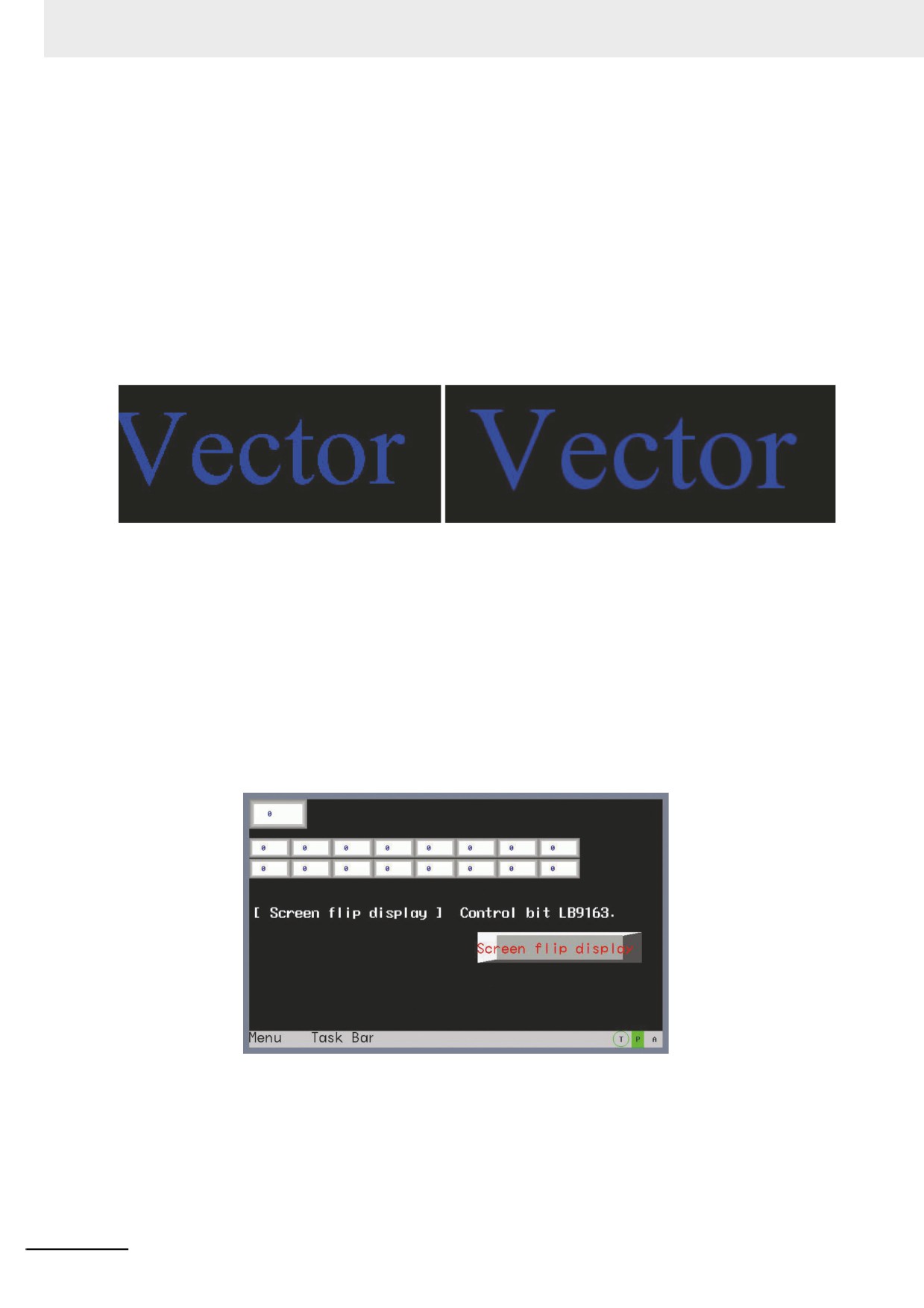
The comparison effect of checking and not checking the [Vector Font Smooth Display] is shown as
below:
The effect of checking [Vector Font Smooth Display]: The effect of not checking [Vector Font Smooth
Display]:
It is obvious that the edges after being handled are more smooth and no-alias.
Flip Screen Display:
The optimal visual angle for the screen of the PT is front view. If the screen needs to be seen by the
overlooking method, i.e. from top to bottom, in some special occasions, the display effect will become
poor; and the “Flip Screen Display” is added to turn the screen reversely to obtain the same display
effect as viewed from the front.
There are 2 methods for Flip Screen Display:
Method 1: Enter [PT Extended Properties] tab in PT Property, check [Flip Screen Display], and the
display is reversed after it is downloaded to the screen. And the screen will keep as Flipped Display
after the power failure or restart of the screen.
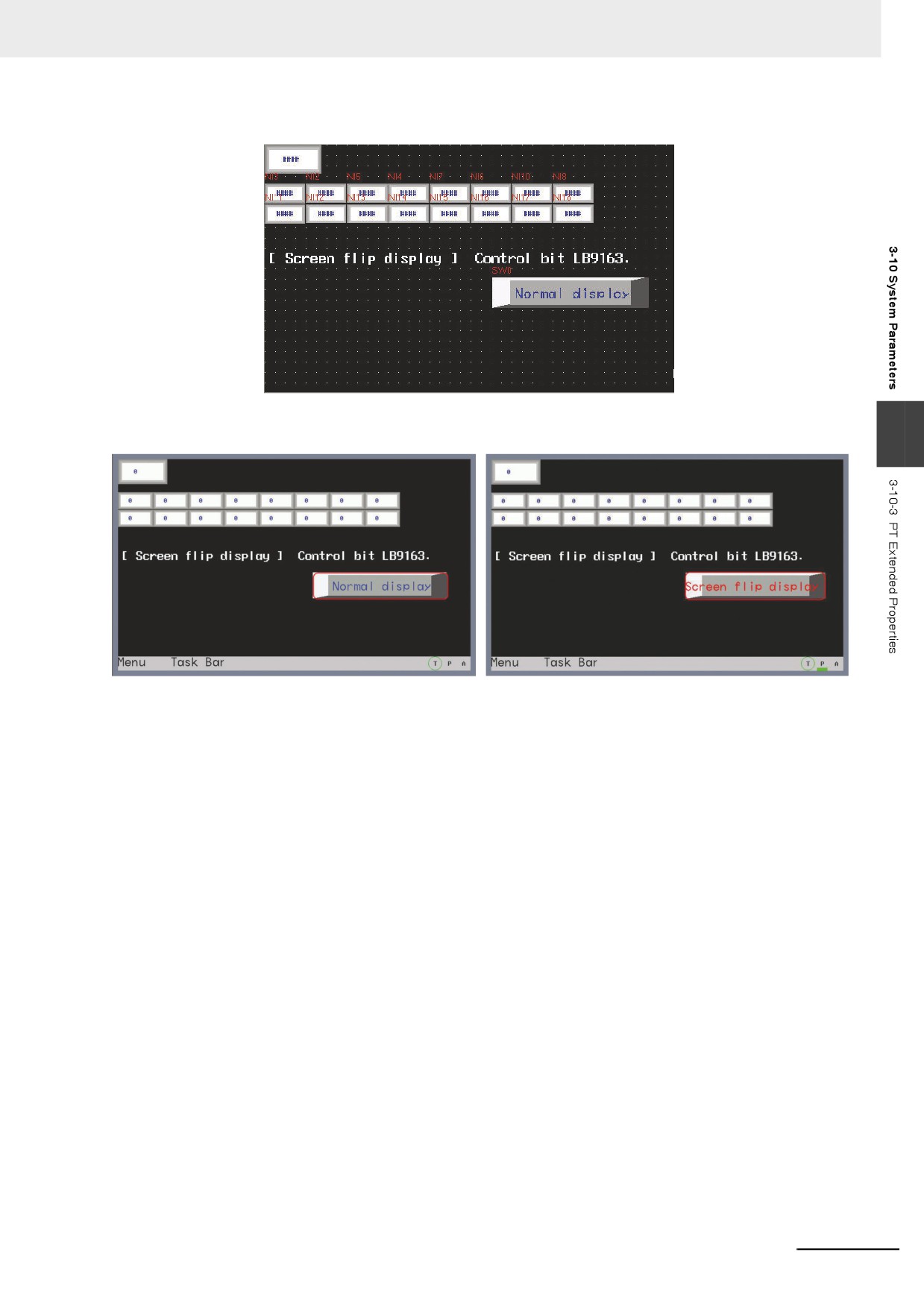
Perform the offline test and the effect is as shown below:
Method 2: The flipping of the screen is controlled by the local special memory LB9163 (LB9163 is
read/write type.). When LB9613 is turned ON, the screen is displayed vertically-flipped. When the
flipped screen display function is controlled by LB9163, the flipping function can’t be maintained after
the power failure or restart of the screen.
Example: Place a Bit Switch with the address of LB9163 and Property of “Alternate” in the screen.
3-300
3 Functions of NB-Designer
When LB9163 is ON, the display is flipped; while LB9163 is OFF, the screen is displayed in the normal
direction. Perform the offline test and the effect is as shown below:
3
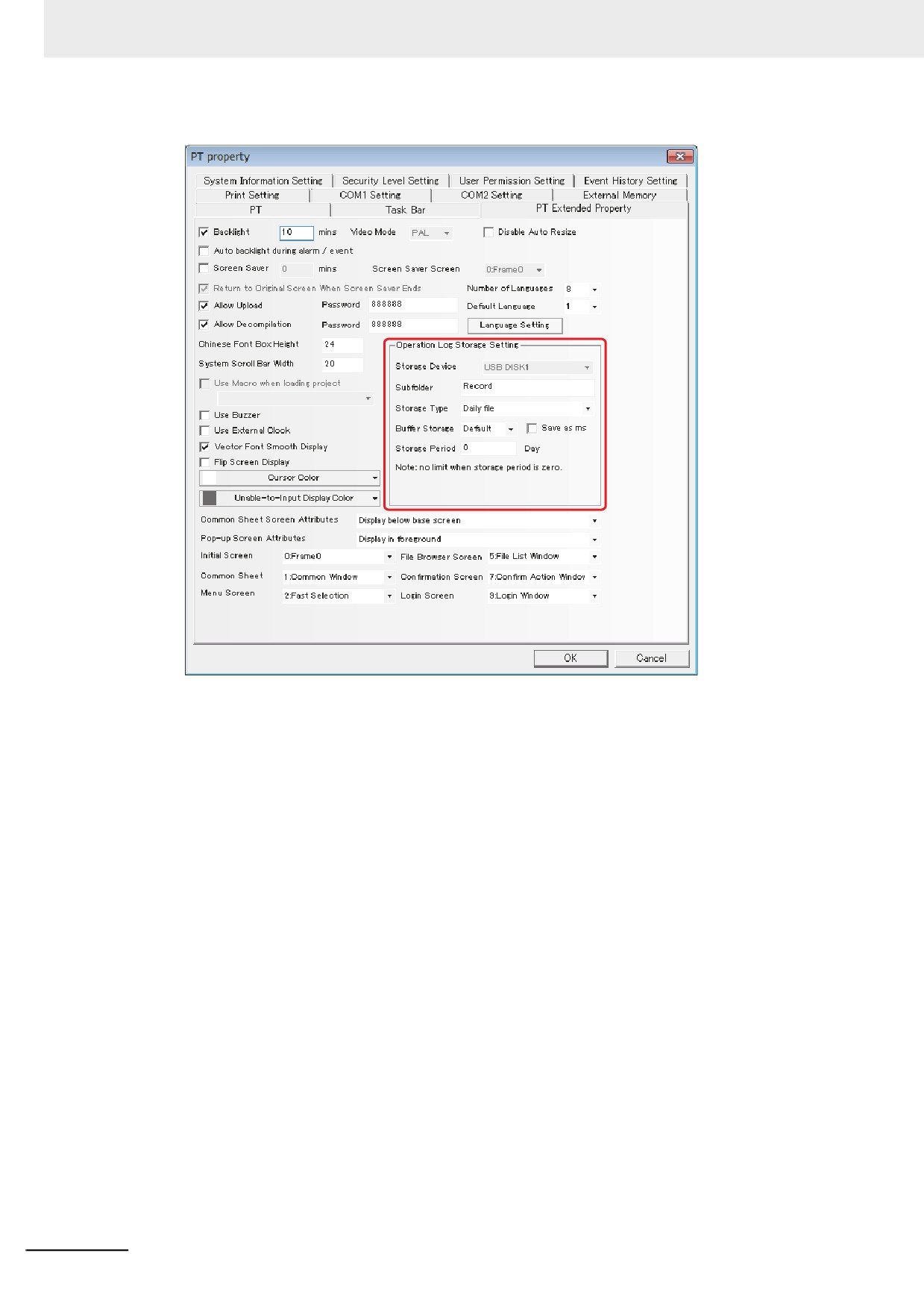
Operation Log Storage Setting: Stores the operation log in the specified subfolder of the specified
storage device. Two storage types are available; One is to "store the
operation log by day and record them into the file named in "yyyy
mmdd" form", and the other is to "store the operation log by the
number of records and record them into the file with the name of
"Subfolder Name".
By setting the size of Buffer Storage, the data is written into the
memory when the size is reached to the pre-set size. (Default:
writing operation will immediately be performed)
By setting the Storage Period, the upper limit can be set for the
operation logs amount with the unit of "Day" for Daily File and
"Record" for Single File. When the [Daily File] is selected, the file will
be named in "yyyy mmdd" form and the Storage Period is the upper
limits of the number of CSV files in this path; if the Storage Period is
exceeded, the oldest file will be deleted. If the [Single File] is
selected, the file will be named in "Subfolder Name" form, the
Storage Period is the upper limit of the records archived in the file;
the archived records are reached to the Storage Period, the storage
will not be continued.
By setting the Save as ms, the data sampling time accuracy
changes to the millisecond and records it into the CSV file.
3-301
3 Functions of NB-Designer
Common Sheet Screen Attributes: Determines the Common Sheet for the project program to be
displayed above or below the Base Screen.
Pop-up Screen Attributes: Specify the pop-up screen whether if it is displayed on top of the screens
or not.
Initial Screen: The screen is displayed at first by the PT after the unit is started in user project mode.
The default is Frame 0.
Common Sheet: Refers to the No. of Common Sheet of the project. The default is Frame 1.
Menu Screen: Refers to the No. of Menu Screen of the project. The default is Frame 2.
File Browser Screen: Refers to the No. of Browser File Screen of the project. The default is Frame 5.
Confirmation Screen: Refers to the No. of Confirmation Screen of the project. The default is Frame 7.
Login Screen: Refer to the No. of Login Screen of the project. The default is Frame 9.
Unable-to-Input Display Color:
The role of invalid component marks: When the enable condition isn’t met or is invalid, using this option
can set invalid component mark to indicate this component can’t be used currently and the touch is not
effective. Only the control components such as switch and Command Button component etc. can use
invalid component marks, and the display components such as Lamp and Word Lamp component etc.
don’t support the invalid component marks.
3-302
3 Functions of NB-Designer
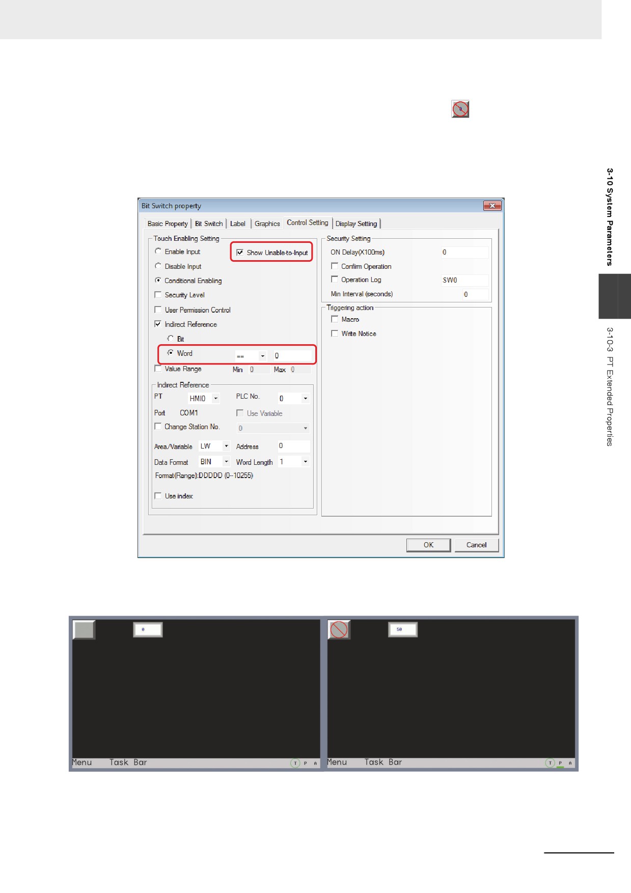
Example: When the value of LW0 is 0, only M0 (Bit Switch) can be operated. When the value of LW0
isn’t 0, M0 (Bit Switch) canot be operated, and the invalid mark
will be displayed in the
color which was specified.
(1) Setting of Unable-to-Input Display Color: Double-click PT Property and enter [PT Extended
Property] tab to select “red” as the Unable-to-Input Display Color.
(2) Place one Bit Switch, i.e. M0, and set the enable conditions in the [Control Setting] tab for it,
and then select [Conditional Enabling], [Word] LW0=0 and select [Show Unable-to-Input].
3
(3) Place one Number Input component LW0.
(4) Perform the offline test. And when LW0=0, M0 can be operated; and when LW0=50, M0
can’t be operated and the invalid mark will be displayed. The effect is shown as below.
Cursor Color: Sets the cursor color for the component with the cursor such as Number Input
component and Text Input component etc.
3-303
3 Functions of NB-Designer
3-10-4
System Information Setting
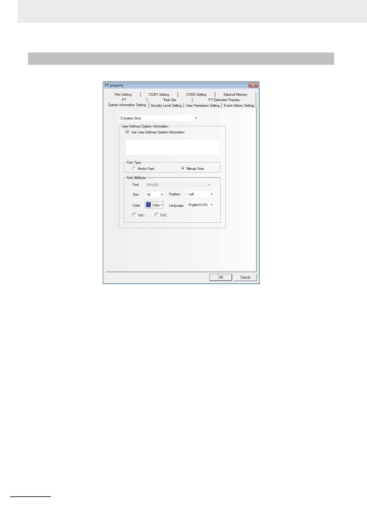
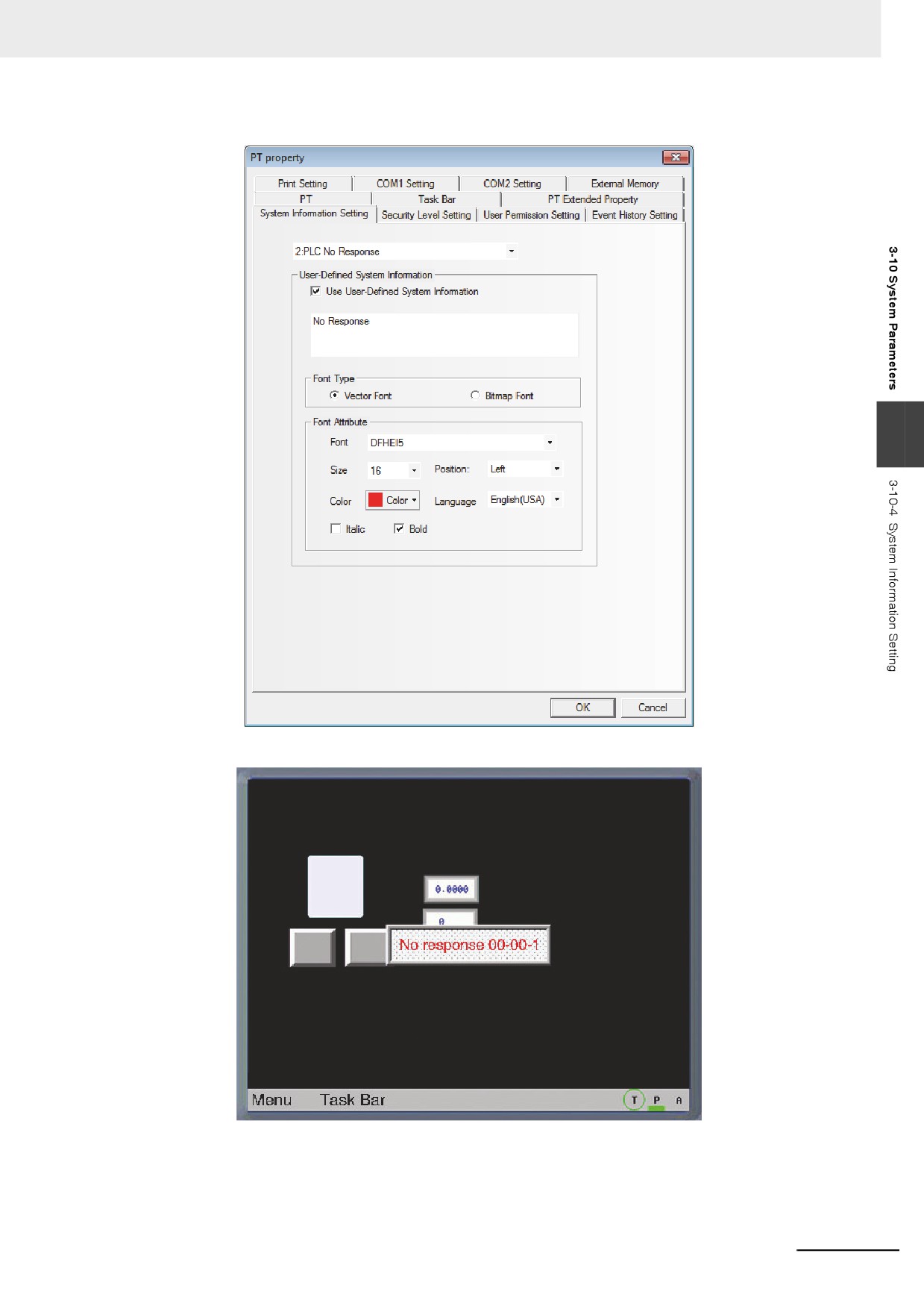
The message in default can be changed to the required text.
Enter the [System Information Setting] tab in PT Property, select the [Use User-Defined System
Information] option to enter the corresponding text to the item of selected system information in the text
box. This text supports Vector Font and Bitmap Font, as shown above.
Example: Change “PLC No Response” to “No Response”.
(1) Enter the [System Information Setting] tab in PT Property.
(2) Select “2: PLC No Response” in the drop-down box of the system information, and check
the [Use User-Defined System Information] option and input “No Response” in the text
input box.
(3) Use the Vector Font with the following settings, i.e. AR PL UMing CN, the size of 16, red
and Bold.
3-304
3 Functions of NB-Designer
3
When the PT can’t perform communications with PLC, “No Response” will be displayed.
3-305
3 Functions of NB-Designer
3-10-5
Security Levels Setting
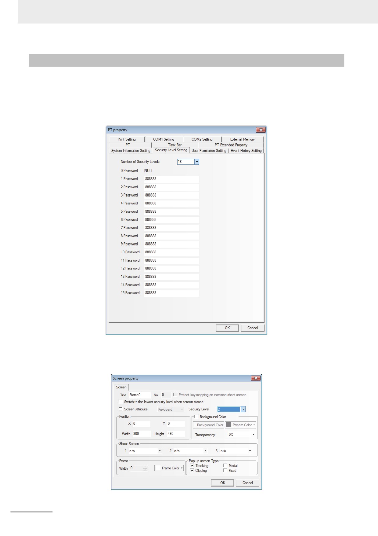
The security level is classified into 16 levels (0 to 15) in the NB-Designer. One 8-digit number password
can be set for each level at the request of the users, and the greater the level number, the higher the
level. 15-level is the highest and 0-level is the lowest. When the security level is 0, it means no
password. 0 can’t be used for setting the password.
Number of Security Levels is 3 by default in PT Property, and it can be opened to 16 levels in the
Security Levels Setting tab.
After the security level password is set, the user can use each group of specified passwords to perform
screen and component managements. For example, after the screen security level is set to “2”, the
screen can be switched to by inputting the user password; otherwise this screen can’t be entered
during the operation.
3-306
3 Functions of NB-Designer
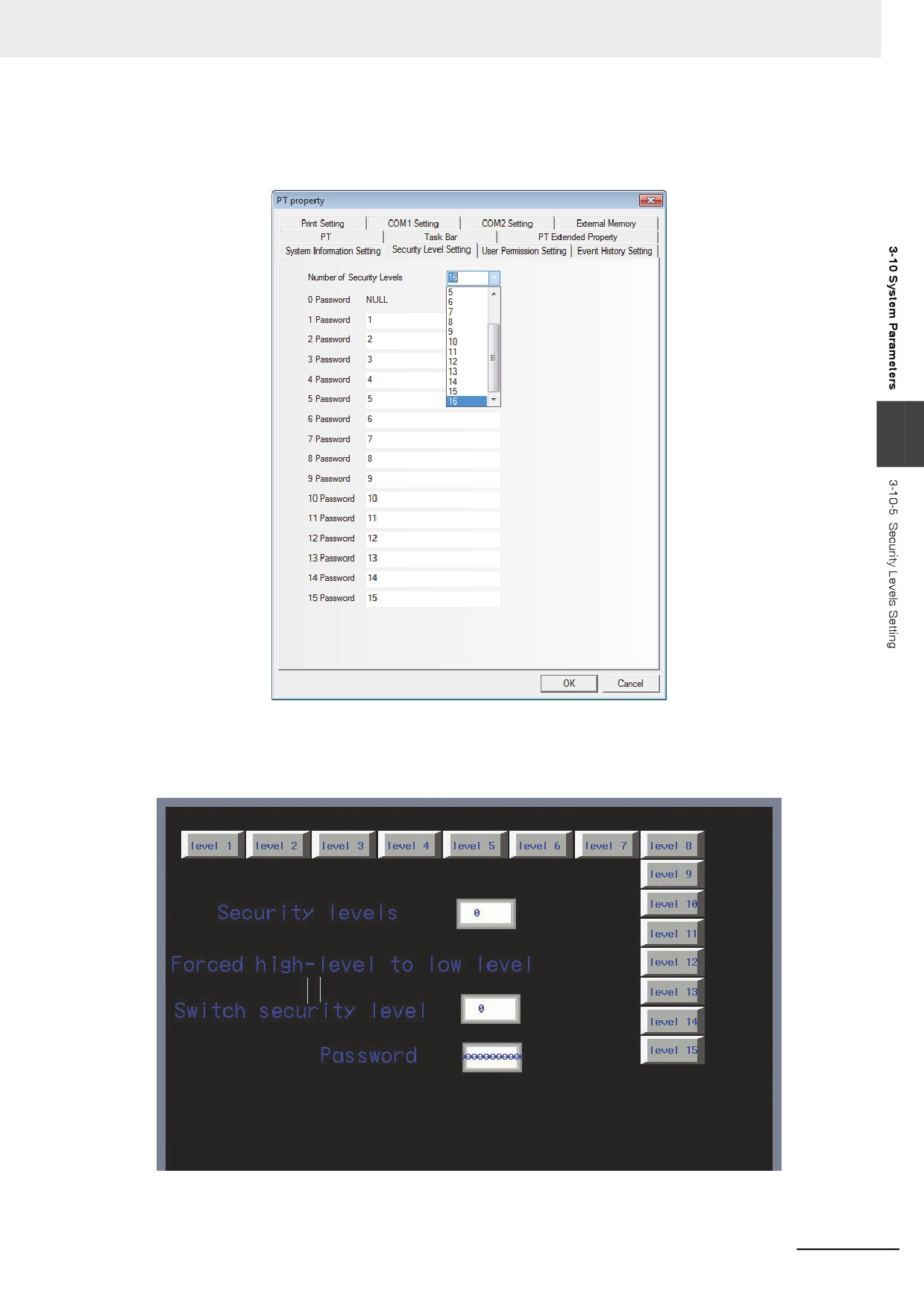
Example: Set 16-level security passwords for the project.
(1) Set “Number of Security Levels” in PT Property to 16 accompanying the passwords for
each level of security level 1 to 15.
3
(2) Use a double-word Number Input component with address of LW9040 as Frame 0 for
inputting the password. LW9042 is used to display the security level and LW9043 is used to
switch the security level forcefully. The 15 Function Keys are used to switch Frame 8 to
Frame 22 respectively.
3-307
3 Functions of NB-Designer
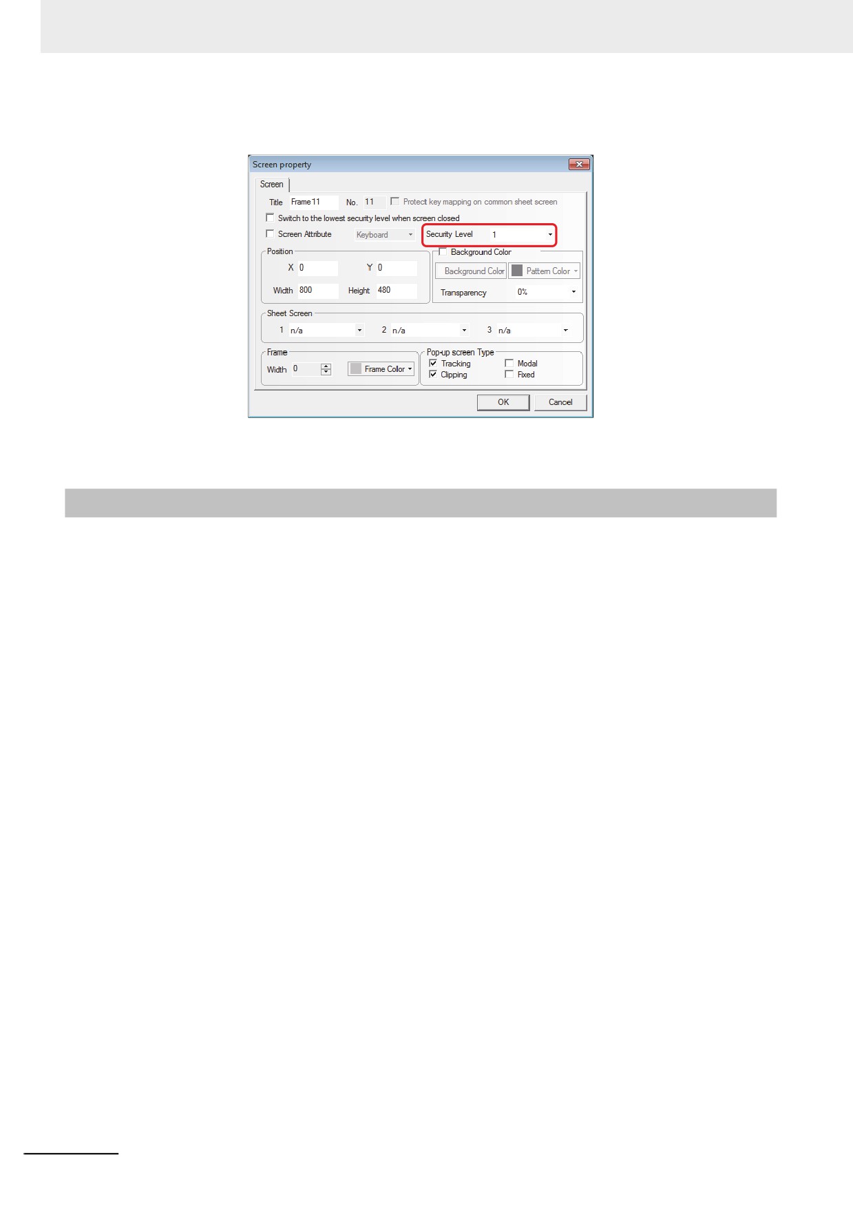
Set the screen security levels and make Frame 10 correspond to Security Level 1, Frame
11 correspond to Security Level 2, …, and Frame 24 correspond to Security Level 15.
(3) Perform the offline test or download it to the screen to check the password level function.
3-10-6
User Permission Setting
The software opens 32 users and 32 operation permissions for free use. The users and operation
permission can be set separately, and the operation permission is not limited to the users. And the
online user addition/deletion and permission modification can be done in the PT.
1
User Permission Setting
Check the [Enabled] option and input the contents to the User Name, Password, Logoff Time
and Authorization.
User Name: Refers to the login name and the defaults are usr0 to usr31. The user name
supports any characters.
Password: Refers to the login password, and the default is 888888. The password only
supports the number instead of the other characters. The password ranges from 1 to
4294967295. And 0 can’t be used for setting password.
Logout Time: Refers to the valid time for this user permission and the default is 10 minutes.
After 10 minutes, this user permission will be automatically cancelled, and the operation
permission can be obtained by inputting the password again. The logoff time ranges from 0 to
4294967295 minutes. When the Logout Time is specified to 0 minute, the user permission is
always valid.
3-308
3 Functions of NB-Designer
For example:
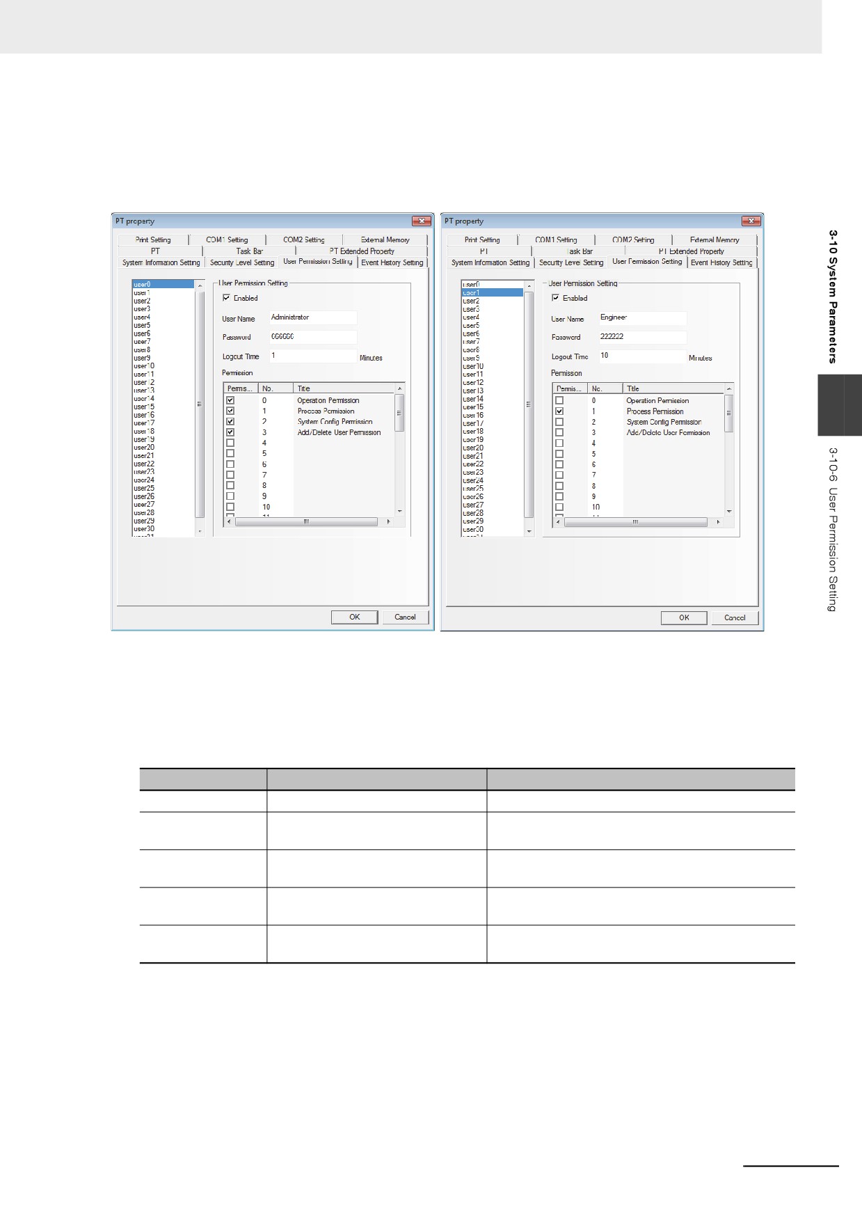
(1) For the User Permission Setting of User 0: Check the [Enabled] option and set the User
Name to Administrator, Password to 666666 and Logout Time to 1 minute. Assign 4
Authorities, i.e. Operation Permission, Process Permission, System Config Permission and
Add/Delete User Permission respectively for the “Administrator (User 0)”.
3
(2) For User Permission Setting of User 1: Check the [Enabled] tab and set the User Name to
Engineer, Password to 222222 and Logoff Time to 10 minutes. Assign 1 Authority, i.e.
Process Permission to the “Engineer (User 1)”.
Besides the User Permission Setting in PT Property, using the following internal memory
allows the operations concerning the user permission.
Addresses
Functions
Descriptions
LW9486~LW9501
Input the login user name.
32 characters max.
LW9502~LW9503
Input the password corresponding
Double-word
to the login user.
LW9504~LW9505
Display the current user authority.
Double-word, read-only component, the
corresponding 32 authorities.
LB9165
Execute the user login.
After it is turned ON, the login operation is
performed, and later it is turned OFF automatically.
LB9166
Execute the user logout.
After it is turned ON, the logout operation is
performed, and later it is turned OFF automatically.
2
Dynamically Add/Delete User Permission during operations.
Perform adding or deleting the user permission during operations in the PT. The following
internal memory is used for adding or deleting the user permission during operations.
3-309
3 Functions of NB-Designer
Addresses
Functions
Descriptions
LW9486~LW9501
Input the login user name.
32 characters max.
LW9502~LW9503
Input the password
Double-word
corresponding to the login user.
LW9506~LW9507
Assign the user authority.
Double-word, Read/Write component, 32 authority
assignments. LW 9506 to LW 9507 corresponds to
32 authorities (No. 0 to 31) and LW.B corresponds
to each bit in LW 9506 to LW 9507. For example:
LW.B 9506.0 represents the authority of No. 0; and
LW.B 9506.A represents the authority of No. 10.
LW9508~LW9509
Logout time
Double-word, Unit: minute
LW9510~LW9511
Add/Delete user confirmed
Double-word
password.
LB9167
Add the user permission.
After it is turned ON, the operation is completed and
later it is turned OFF automatically.
LB9168
Delete the user permission.
After it is turned ON, the operation is completed and
later it is turned OFF automatically.
LB9169
Modify the password
After it is turned ON, the current user password will
be modified, and later it is turned OFF
automatically.
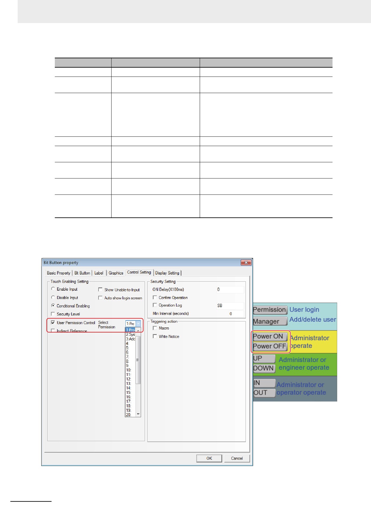
z Setting Permission Control of Component:
Select the [Conditional Enabling] option in the [Control Setting] tab of “Bit Button Component
Property” and check [Use Permission Control], as shown below.
Setting “Use Permission Control” for the component means only the user having this operation
authority can operate the component restricted by this authority.
3-310
3 Functions of NB-Designer
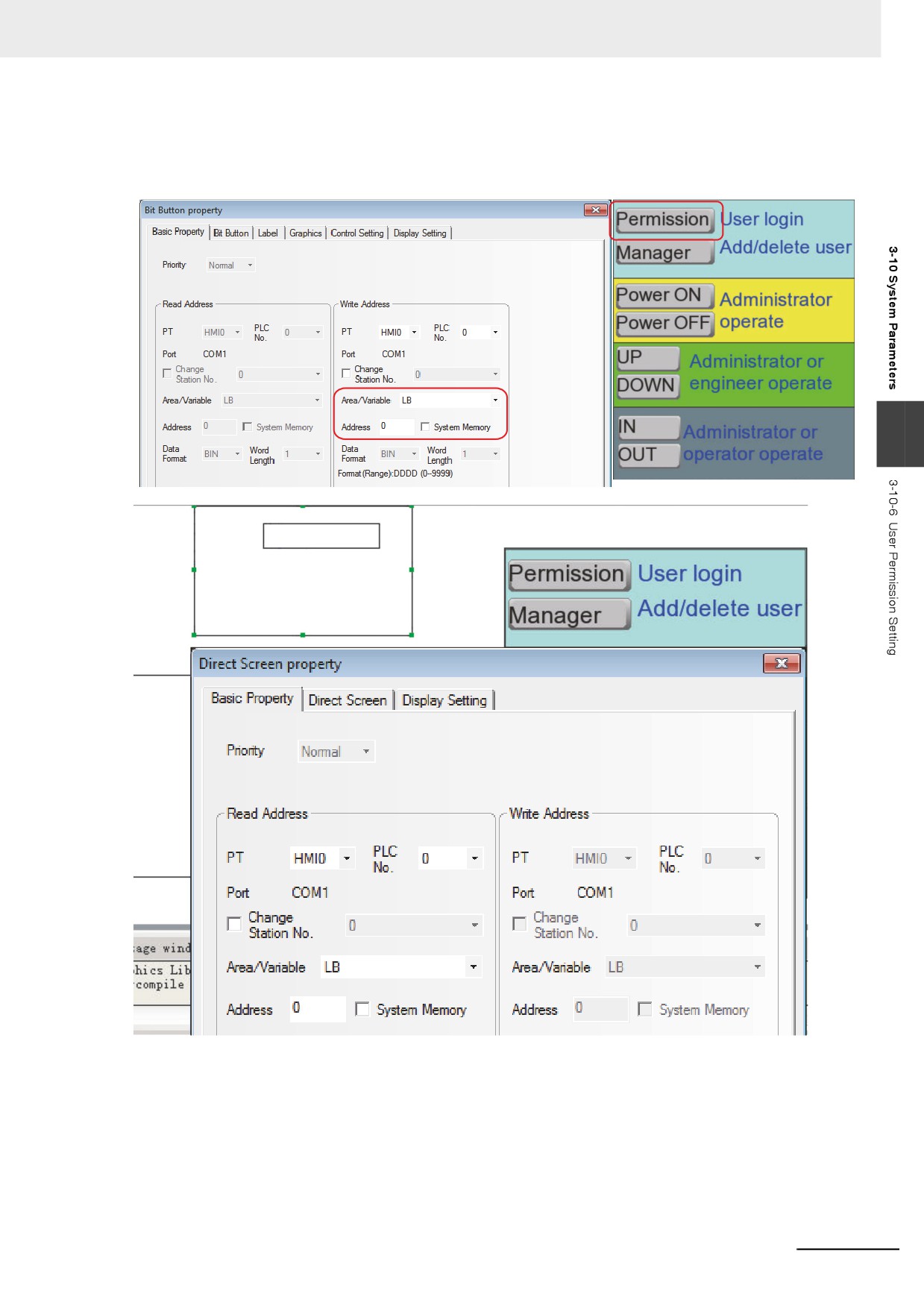
z Login Screen for User Permission
Place one Bit Button component with the address LB0 and the [Set] format and pop-up the input
screen of the user permission password specifying the Direct Screen.
3
Current User: None
3-311
3 Functions of NB-Designer
Create a new screen as the user permission password input screen:
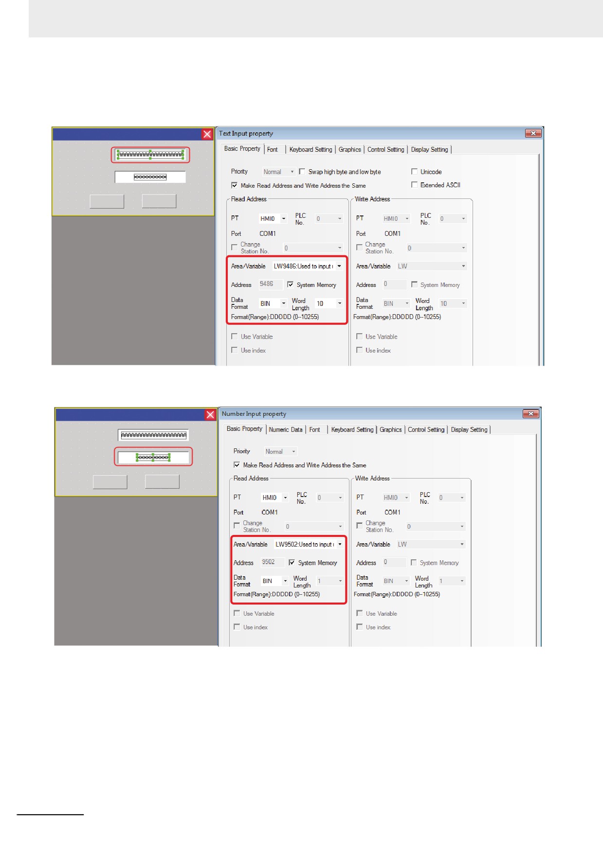
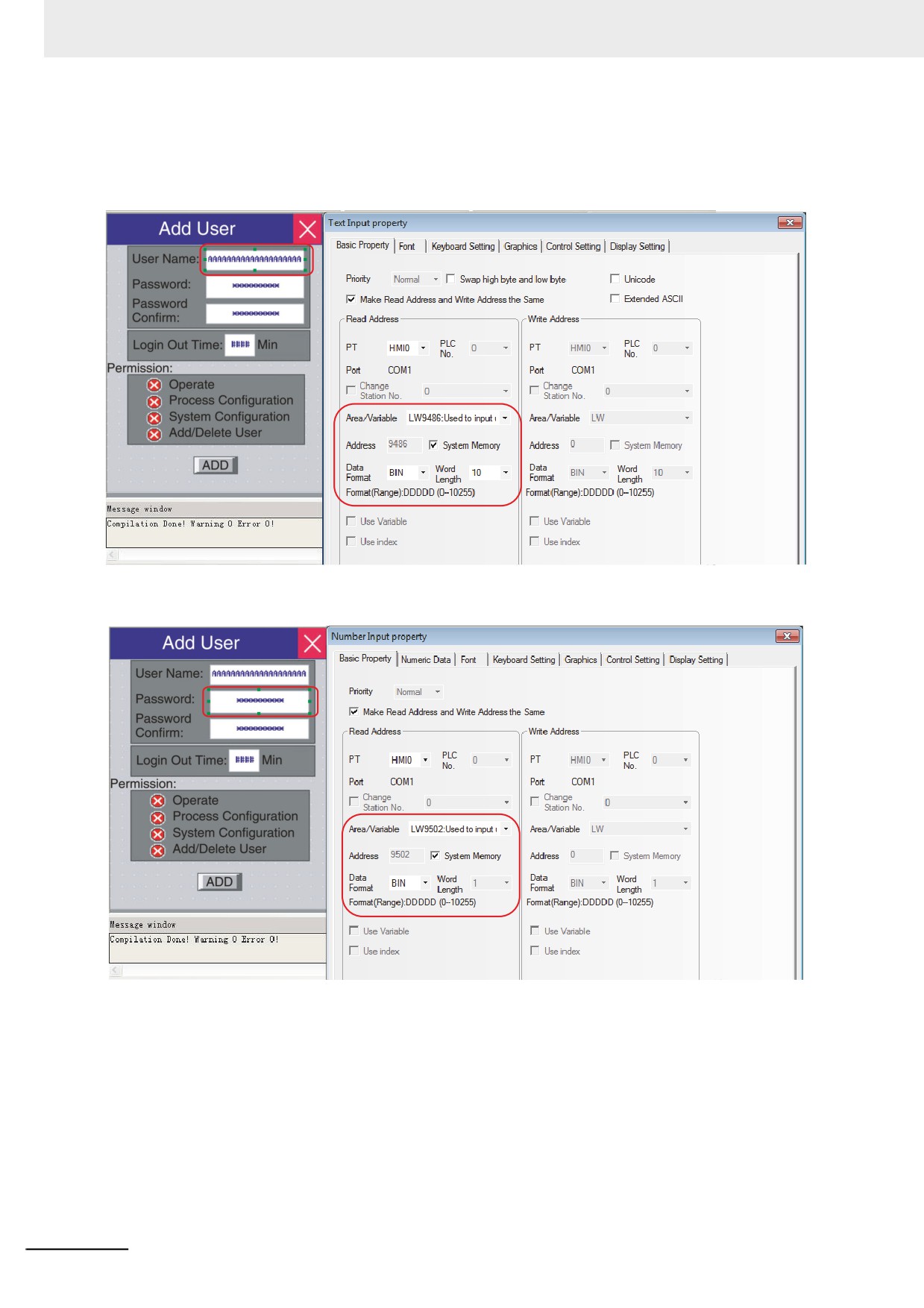
Firstly, place one Text Input component for inputting the user name with the address of LW9486 and
the maximum word length up to 16 (Here it is 10.).
User Login
User Name:
Password:
Login
Login Out
Secondly, place one Number Input component for inputting the password with the address of
LW9502, the word length of 2 and the data type of [password].
User Login
User Name:
Password:
Login
Login Out
3-312
3 Functions of NB-Designer
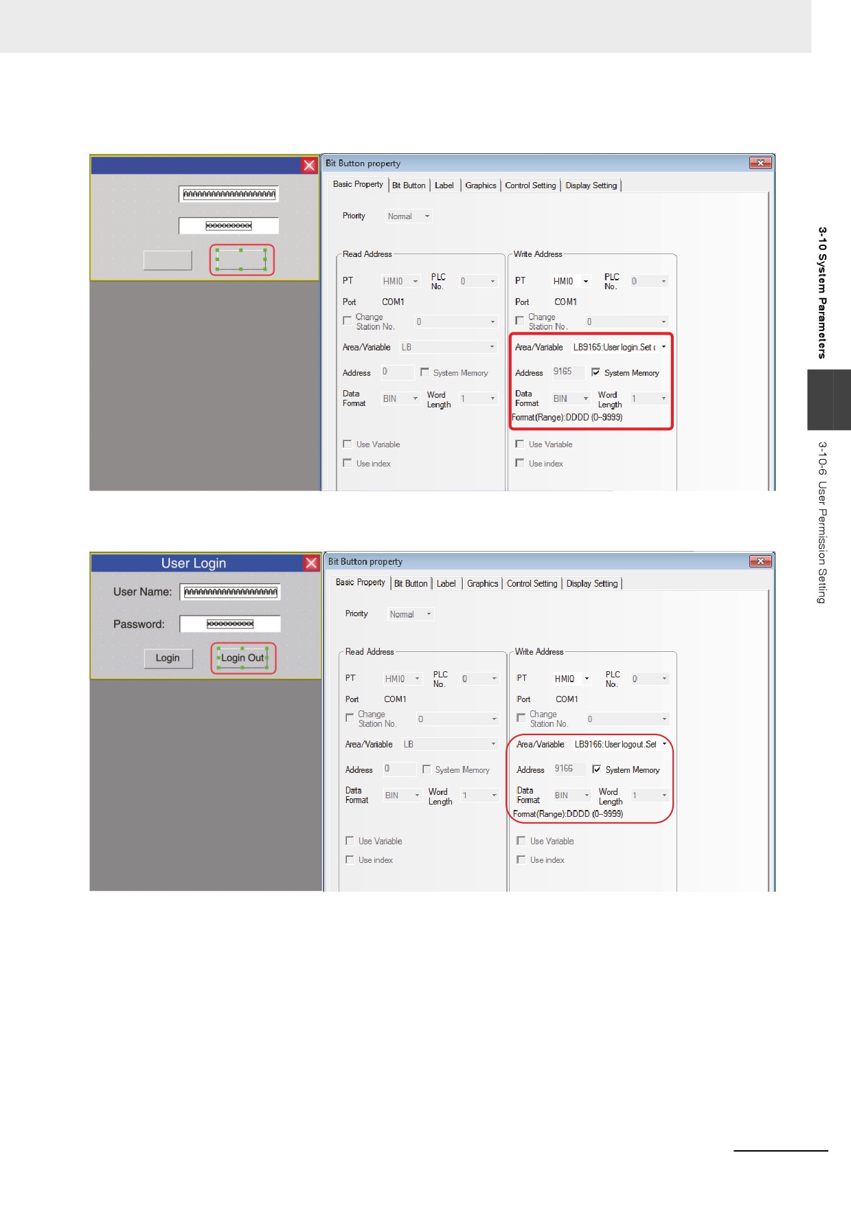
Thirdly, place one Bit Button component to perform “user login” with the address of LB9165, type of
[Set] and the label content of “Login”.
User Login
User Name:
Password:
Login
Login Out
3
Finally, place one Bit Button component to perform “user logout” with the address of LB9166, type of
[Set] and the label content of “Logout”.
3-313
3 Functions of NB-Designer
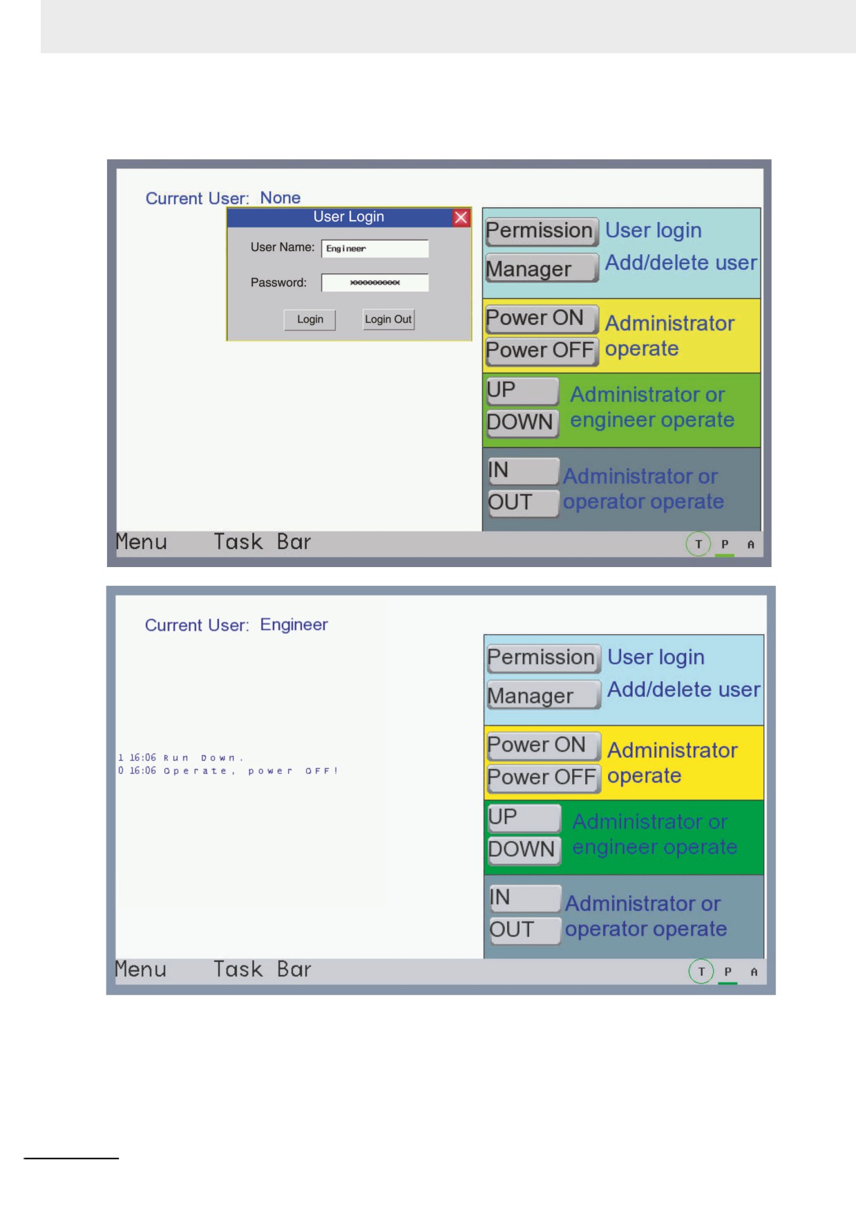
Perform the offline test and the effect is as shown below:
Input “Engineer” in [User Name] and “222222” in [Password] respectively, then click [Login].
3-314
3 Functions of NB-Designer
z Add/Delete User Permission:
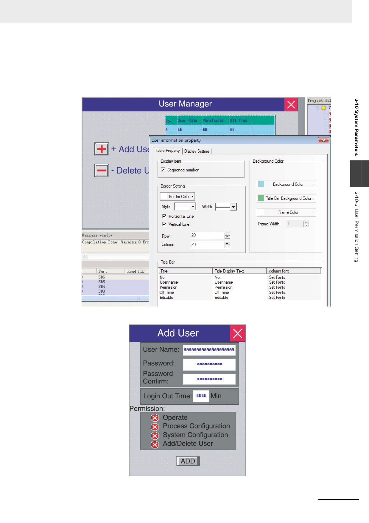
Place one User Information component in Add/Delete User Screen to display the user information of
the current system.
The “Table Property” in the “User Information Property” dialog can be edited according to the
requirement.
3
(a) Add User
3-315
3 Functions of NB-Designer
“Add User” screen contains User Name, Password, Password Confirm, Logout Time
and Permission.
User Name: Place one Text Input component for inputting the user name with the
address being LW9486 and the maximum word length up to 16 (Here it is 10.).
Password: Place one Number Input component with the address of LW9502, the word
length of 2 and the data type of [password] here.
3-316
3 Functions of NB-Designer
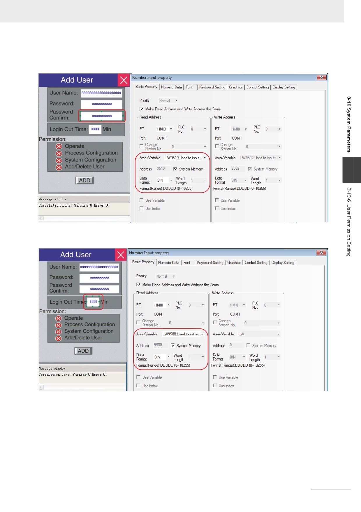
Password Confirm: Place one Number Input component by which the password is
entered again for confirmation with the address of LW9510, the word length of 2 and
the data type of [password] here.
3
Logout Time: Place one Number Input component with the address of LW9508, the
word length of 2 and the data type of [unsigned int] here.
3-317
3 Functions of NB-Designer
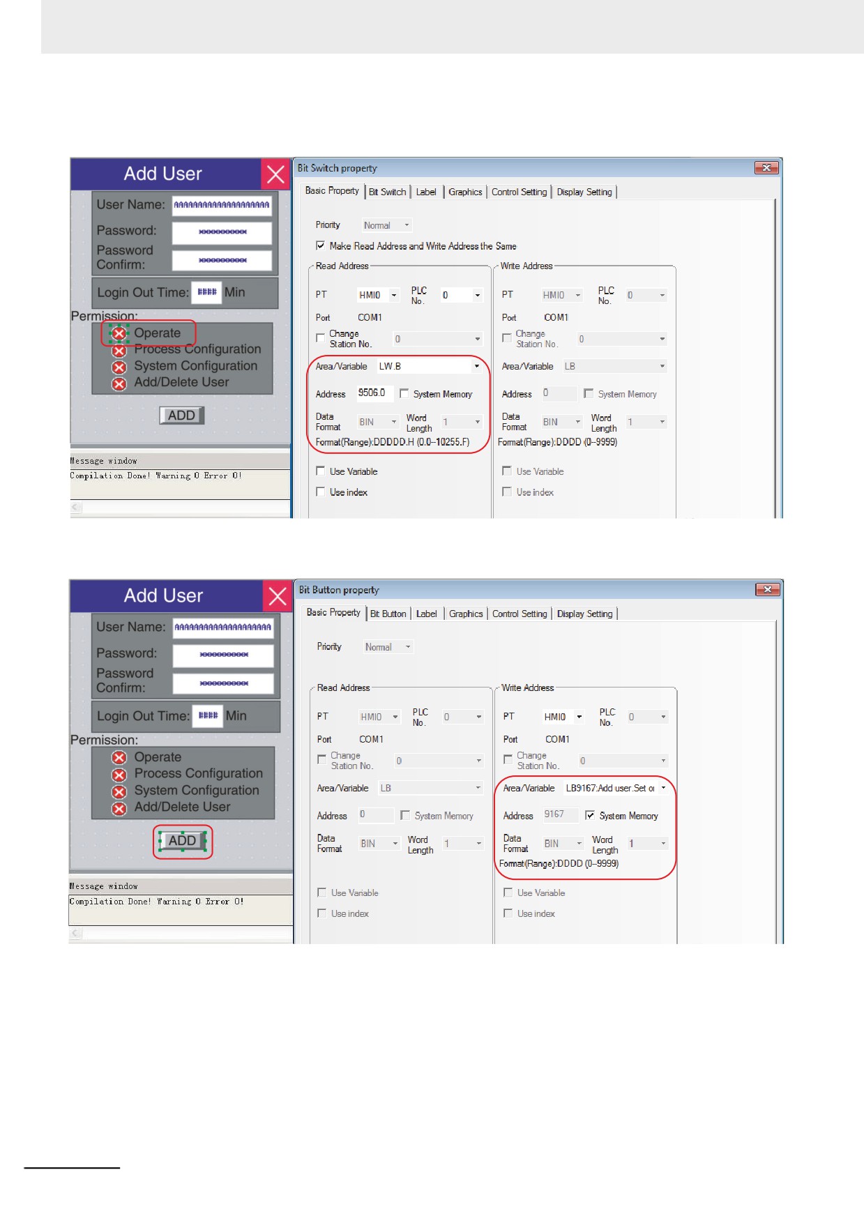
Permission: Place 4 Bit Switches with the addresses of LW.B 9506.0, LW.B 9506.1,
LW.B 9506.2, LW.B 9506.3 respectively and switch type of [Alternate] here.
Add User Operation Confirmation: Place one Bit Button component with the address of
LW9167 and switch type of “Set” for confirming the added user permission.
3-318
3 Functions of NB-Designer
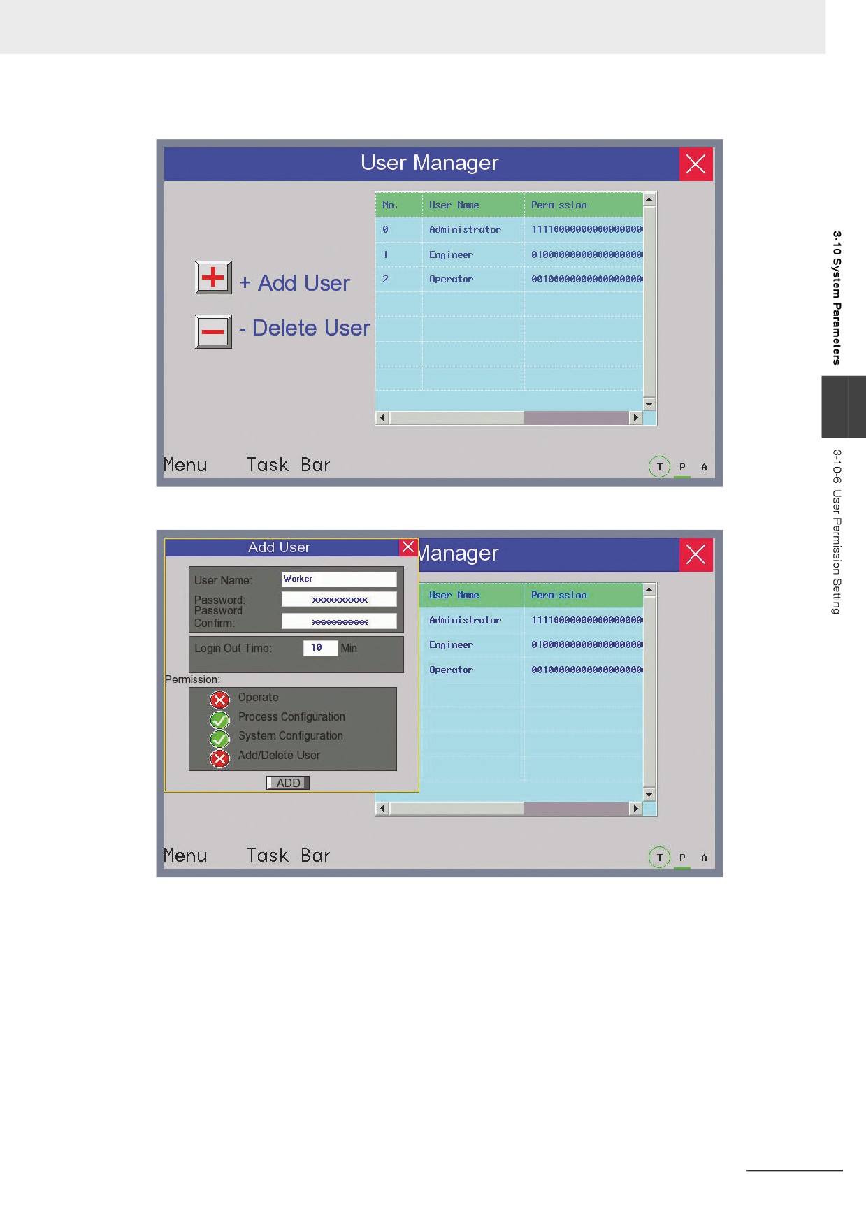
Perform the test and the effect is as shown below:
3
Click [Add User] to make add user dialog box pop up:
3-319
3 Functions of NB-Designer
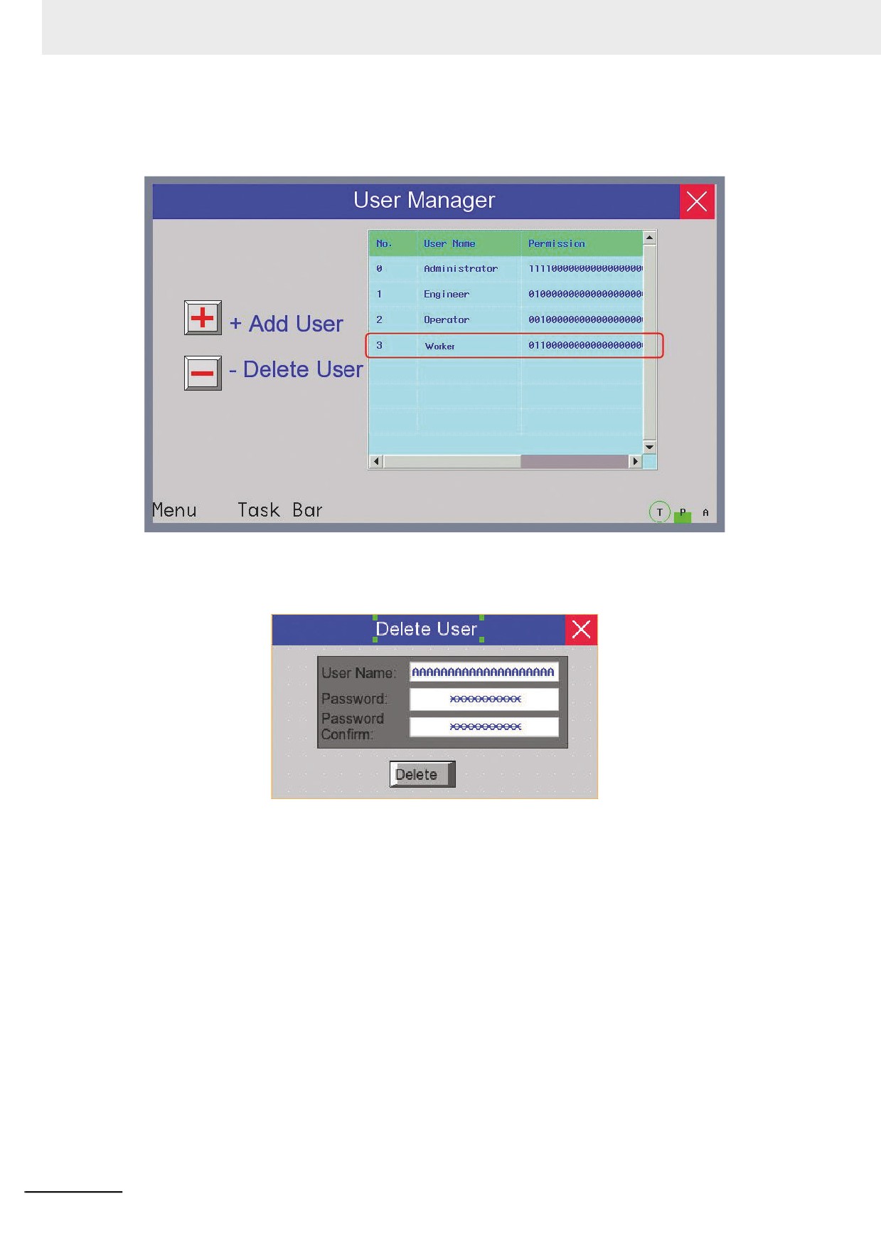
Input the User Name to be added, set the Password and the Password Confirm, and
then set the Logout Time for this user and assign the Permission. After the setting,
click “ADD” to complete “Add User” operation.
(b) Delete User
“Delete User” screen contains User Name, Password, Password Confirm, Delete User
Operation etc.
The settings of User Name, Password and Password Confirm are similar to that of
“Add User”.
Delete User Operation Confirmation: Place one Bit Button component and specify the
address to LW9168 and the switch format to [Set].
Note Delete user permission operation is only valid for the users added to the PT. The users set in the NB-
Designer can’t be deleted.
3-320
3 Functions of NB-Designer
Perform the offline test and the effect is as shown below:
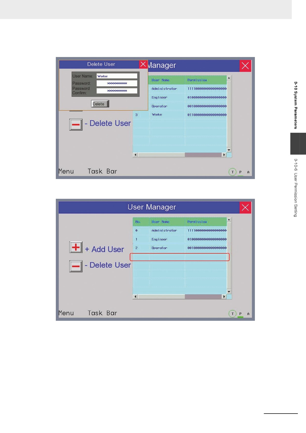
Click “Delete User” to make Delete User dialog box pop up:
3
Input the User Name to be deleted, the Password and Password Confirm for this user, then click
“Delete” to complete the operation of deleting users.
3-321
3 Functions of NB-Designer
3-10-7
Event History Setting
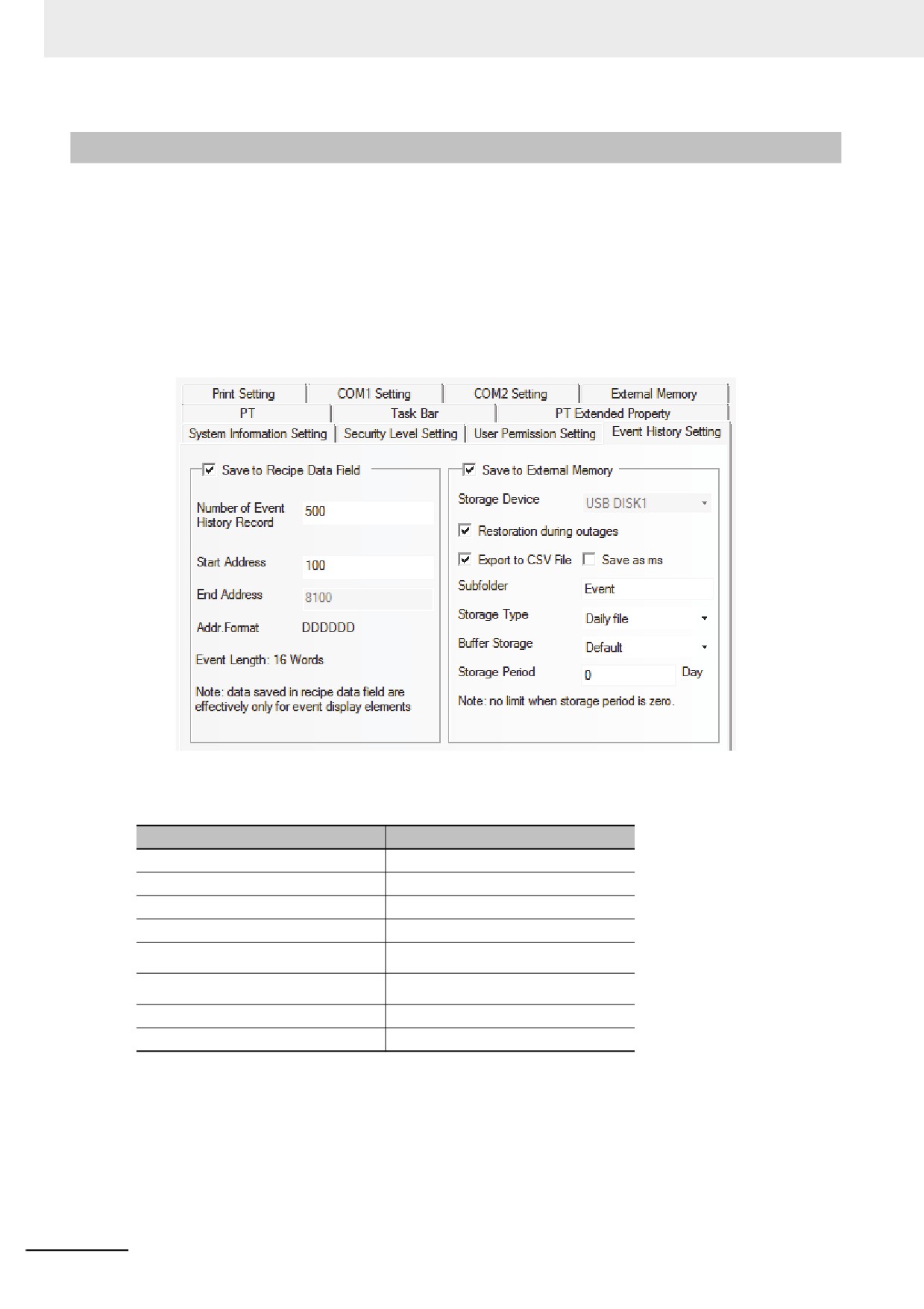
Event History information is stored in the Recipe Data Field.
When the check box [Save to Recipe Data Field] in the [PT Property] is checked, the system stores the Event
History information of executed Event to the Recipe Data Field. Since the system automatically performs the
storing, the user does not have to care about the method to store the Event History information.
The destination to store the data will be specified from the address set in [Start Address] of the system
parameters. The default address is “0”.
The data stored to the Recipe Data occupies 16 words for each event. The example of size calculation to
store the Event Log is shown as below. The data which was stored in the Recipe Data cannot be exported to
external memory.
An example when the starting address of the data to “100” in [Event History Setting] of [PT Property]
In order to store the Even Log Data, the system automatically reserves a memory area starting from
RW100 in the Recipe Data Field. For example, the Event Log management information and 200 of
Event History information are stored as below.
Recipe Data Field address
Data
RW100
1st Historical Event
RW116
2nd Historical Event
RW132
3rd Historical Event
RW148
4th Historical Event
⋅ ⋅ ⋅ ⋅ ⋅ ⋅
⋅ ⋅ ⋅ ⋅ ⋅ ⋅
⋅ ⋅ ⋅ ⋅ ⋅ ⋅
⋅ ⋅ ⋅ ⋅ ⋅ ⋅
RW3268
199th Historical Event
RW3284
200th Historical Event
The size of the stored memory is 200 x 16 = 3200 words. The address of Recipe Data Field is “read
only area”. If writing is performed to the area, it may result in unpredicted condition. Although the user
can specify the starting address freely, pay attentions to the following points.
(1) The specified addresses cannot be specified overlapped with other components and others.
• When the storage period is set, the file deletion is performed at the first sampling after the startup and
every 24 hours. At this moment any files which is beyond the storage period should be deleted.
3-322