OMRON NB-Designer OPERATION MANUAL (NB-series, 2020) - page 10
3 Functions of NB-Designer
3-7-12
User Information
When the system uses User Permission function, the related information of the current login
user can be displayed in the table form by using the User Information component. The User Information
component must be used in combination with the User Permission, otherwise it will not work. Refer to
3-10-6 User Permission Setting (Page 3-308) for the details.
3-7-13
Multifunction
3
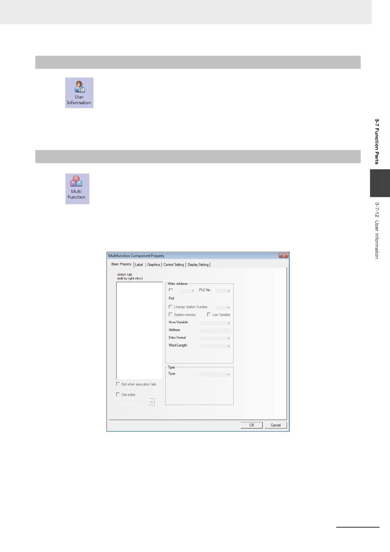
The component which is unified the Bit Button and the Word Switch can operate the both the
bit set and the word set through one key.
The Multifunction component can be created by using the mouse to click [Components] -
[Button/Switch] - [Multifunction] or dragging [Multifunction] component from [Project Library Window] -
[Function Parts] to the Edit Window. The number of Actions which can be set by the Multifunction is 16
at max.
z Process of adding Multifunction component
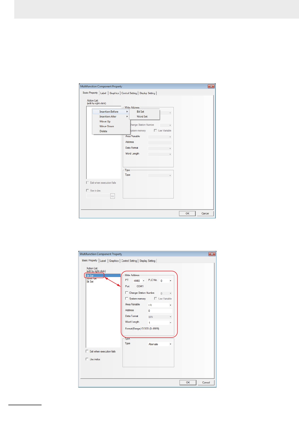
Right-click the mouse in the blank box located in the left side of Basic Properties tab in the
Multifunction Property screen to add the Bit Set or Word Set in the procedure as follows.
1
Add the actions (Bit Set and Word Set). Right-click the Action List to select [Insertion Before] or
[Insertion After] option to change the execution order of the component.
3-233
3 Functions of NB-Designer
2
According to the order to be executed, change the position of the action which was added.
Right-click the Action List to select [Move Up] or [Move Down] option to change the execution
order of the component.
3
In order to delete the action which was added, right-click the Action List to select [Delete]
option to delete this component.
4
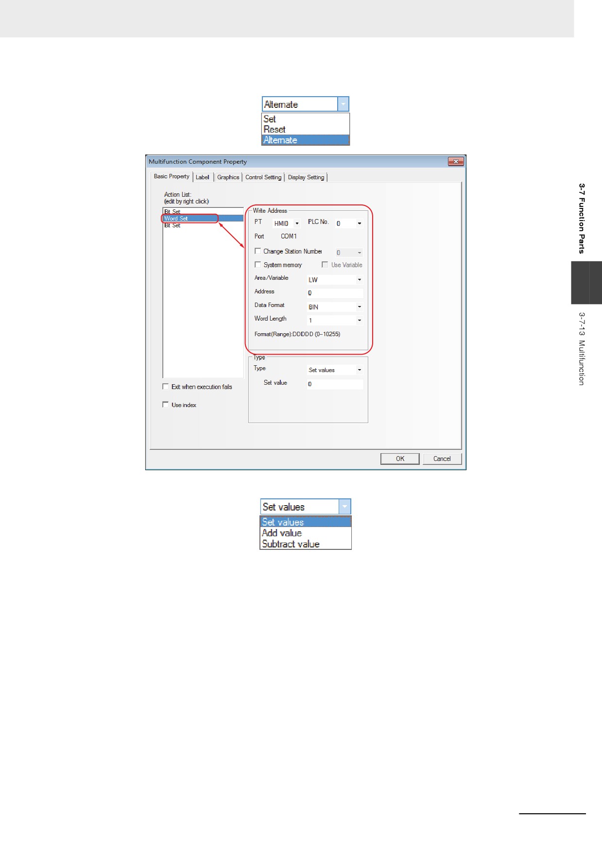
Edit the Property of the Action.
The Property of the Action which was added (Bit Set and Word Set) can be set for each Action
at the right area in the [Basic Properties] tab.
3-234
3 Functions of NB-Designer
The Bit Set support the Types of [Set], [Reset], and [Alternate] only.
3
The Word Set support the Types of [Value Setting], [Add Value], and [Subtraction Value] only.
5
If the function specified according to the Action List order (ascending order) is failed to execute
normally, set the executing operations of the Multifunction by the [Exit when execution fails]
checking box.
• Checking the check box
When executing the function in the order of the Action List, if the specified function cannot be
executed, the execution of the Multifunction is quit at the moment and the Action on the List
is not executed.
• Unchecking the check box
Even if the specified function cannot be executed, when executing the function in the order
of the Action List, the next Action on the List will be executed.
3-235
3 Functions of NB-Designer
3-7-14
Event Display
Event Display is used to make the event information logged in [Event Setting] database
and meeting the current triggering conditions displayed scrolling from the right to the left.
z Event Display Property
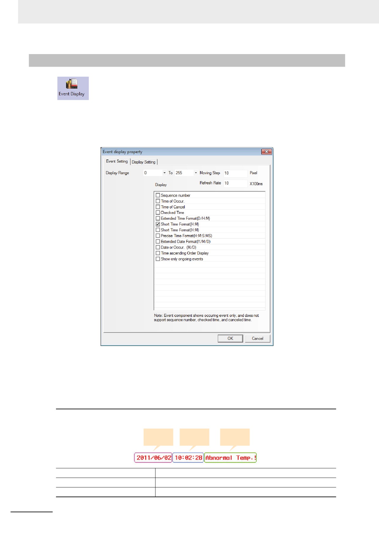
1
Event Setting tab
Display Range: Specify the range of displaying types (formats) of the event.
Moving Step: The pixel point of the width to display the event information in loopy way in units
of pixel.
Refresh Rate: The period to refresh the display of the event information in loopy way in units
of 100ms.
Display: The contents are as follows.
For the displayed format of event information, all the selected format information will be displayed before the
event information.
Date of
Time of
Event
Occur.
Occur.
content
Time of Occur.
The time when the event is triggered.
Extended Time Format (D/H: M)
The time format is displayed as Day/Hour: Minute.
Short Time Format (H: M)
The time format is displayed as Hour: Minute.
3-236
3 Functions of NB-Designer
Standard Time Format (H: M: S)
The time format is displayed as Hour: Minute: Second.
Precise Time Format (H: M: S: MS)
The time format is displayed as Hour: Minute: Second: Millisecond.
Extended Date Format (Y/M/D)
The date is displayed as Year/Month/Day.
Date of Occur. (M/D)
The date is displayed as Month/Day.
Time ascending Order Display
Checking this option means the event time ascends from the front to
back with the latest event information at the end, as shown below:
Not-checking this option means the event time descends from the
front to back with the latest event information at the front, as shown
below:
Note 1
The Event Display only displays the occurring event, and dose not support “Sequence No.”, “Time of Can-
cel” and “Check Time”.
2
Once the triggered event information is unmatched, the unmatched event will not be displayed in the
Event Display anymore.
3
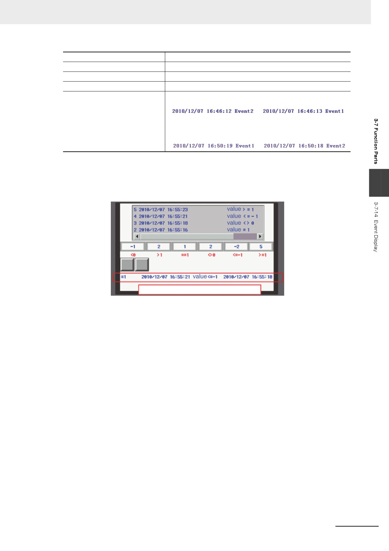
The effect of offline test is as shown below.
Current trigger event is displayed in the Event Display.
3-237
3 Functions of NB-Designer
3-8
Project Database
3-8-1
Text Library
Text Library can be used to store the text contents needed by the project, thus preventing
the label with the same text from being input frequently. In addition, Text Library can be used to the
conditions with the requirement of multi-language support to realize the switching among the multiple
languages for the PT Edit screen. NB-Designer currently supports up to 32 kinds of languages setting.
1
Text Input
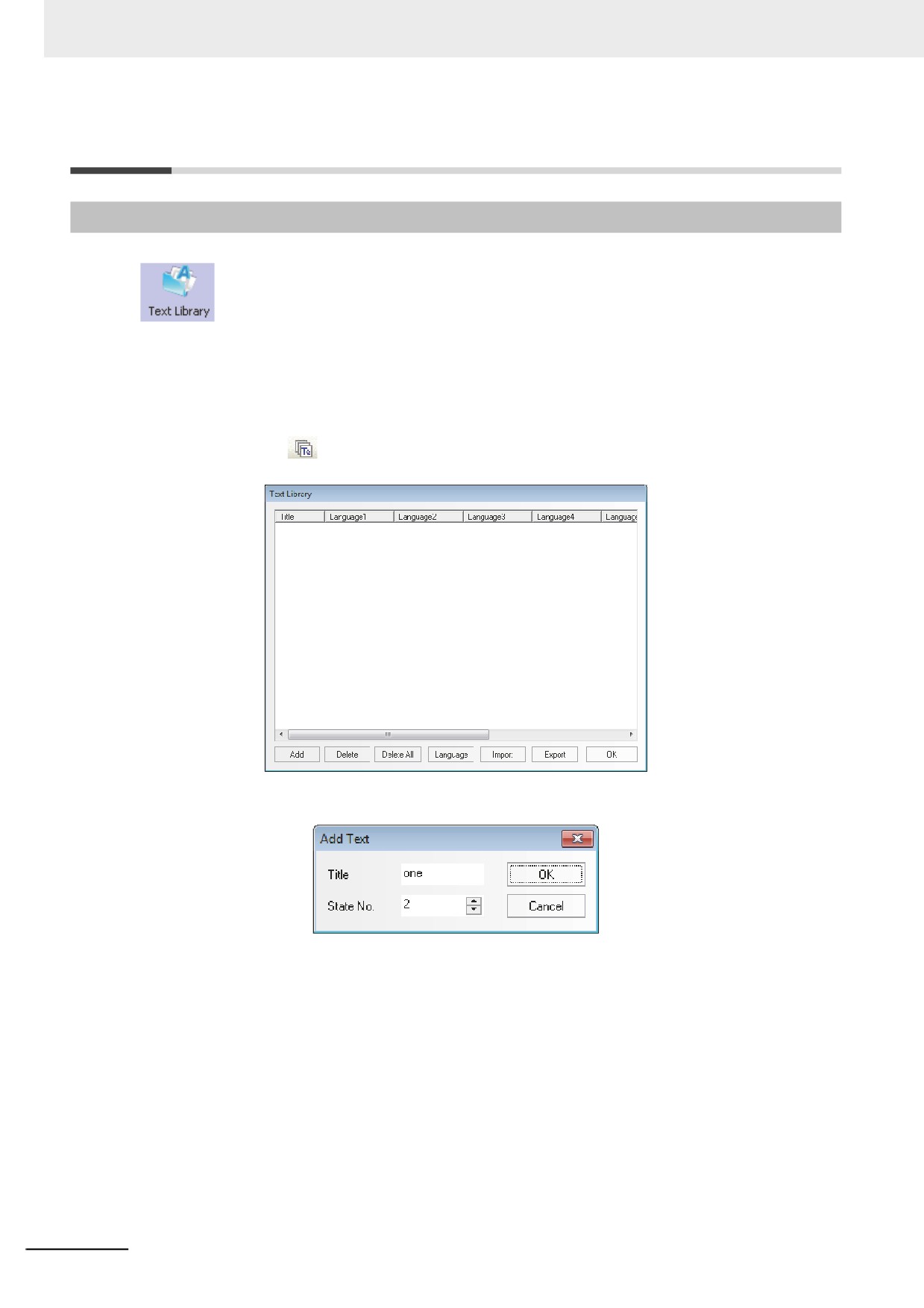
(1) Pressing
icon or clicking [Text Library] in the [Project Database] of the [Project
Library] allows the Text Library to pop up.
(2) When the following “Add Text” dialog box appears after “Add” being clicked, fill in the Title,
State No. and click “OK” to proceed to the next step.
Note Once the text title is registered, it cannot be modified in the [Text Library] dialog box.
3-238
3 Functions of NB-Designer
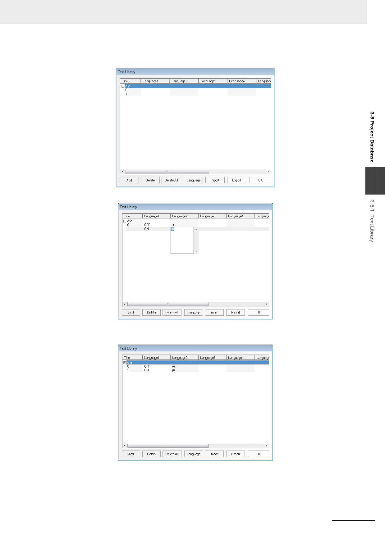
(3) The text added just now has been in the Text Library already, and click the “+” placed
before the “Title” to see the text string.
3
(4) Input the text in each language for each state, as shown below.
(5) If you use 2 states, it just needs to input the corresponding text to state 0 and state 1
respectively for each language, and then click “OK” after the completion of the text addition.
3-239
3 Functions of NB-Designer
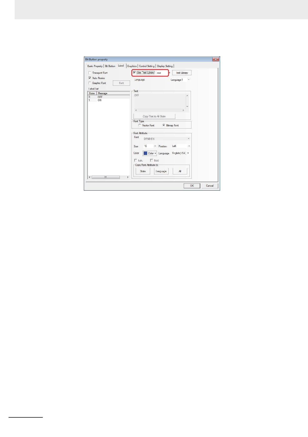
(6) Checking the [Use Text Library] check box in the [Label] tab of dialog box for each Property
allows using the text string which was registered to the [Text Library].
If you haven’t added the text to the Text Library, “Use Text Library” can’t be checked and is
always grayed out until you have added the text into the Text Library.
2
Multi-language Switching
The switching among the multiple languages can be realized by modifying the value of special
register system memory (LW9130). As long as the value of LW9130 is changed in any one of
screens, the displayed text will switch to the text (language) corresponding to the value being
changed to, and the language of the whole system will be changed regardless of the condition
of the current screen. Only resetting the value of LW9130 can make the language switched
again.
It is based on the system special memory LW9130 to realize the multi-language switching in
the Text Library.
That’s to say:
When LW9130 is 0, the contents corresponding to Language 1 in Text Library will be
displayed;
When LW9130 is 1, the contents corresponding to Language 2 in Text Library will be
displayed;
When LW9130 is 2, the contents corresponding to Language 3 in Text Library will be
displayed;
and so on.
When LW9130 is 31, the contents corresponding to Language 32 in Text Library will be
displayed;
When LW9130 is greater than 31, the contents corresponding to Language 1 in Text Library
will be displayed.
Note
“Number of Language” in [PT Property]-[PT Extended Properties] can restrict the number of Language(s)
displayed in Text Library. When the Text Library is used for the first time, the default “Number of
Language” is 8. Even if LW9130 is greater than 8, the system can only display the contents
corresponding to Language 1 to Language 8. If the languages to be displayed are greater than 8 [Max No.
of Languages] needs to be increased in [Language Setting] screen with [Number of Language] not
exceeding [Max No. of Languages].
3-240
3 Functions of NB-Designer
“Default Language” in [PT Property]-[PT Extended Properties] refers to the language number to be
displayed in the default Text Library. For example: When Language 2 in the Text Library is English, if
“Default Language” is set to “2”, the text using the Text Library will be displayed as “English” on the
System Screen after PT is powered ON and be switched to another language until the value of LW9130 is
changed.
3
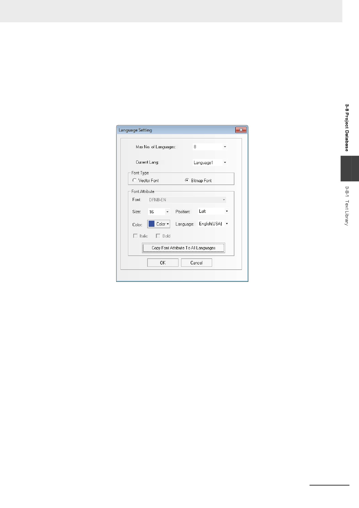
Language Setting of Text Library
Clicking “Language Setting” in [PT Property]-[PT Extended Properties] or clicking “Language”
from the Text Library can open [Language Setting] dialog box to set the global Property of the
text font corresponding to each kind of language.
3
Max No. of Languages: The Text Library supports up to 32 kinds of languages with the
Default Language of 8. If the user needs more than 8 kinds of
languages, the Max No. of Language should be increased.
Current Lang: Refers to the language being edited currently.
Font type: Sets the font type of the language used currently to Vector Font or Bitmap Font .
Font Attribute: Sets the related attributes of the language used currently such as the Font,
Size, Position, Color and Italic and Bold.
Copy Font Attribute To All Language: Copying the font attribute which is edited currently to
all the other languages.
Language: The description of the language which is edited currently. The entry procedure to
the OS of the current PC is displayed.
Note 1
Although the font attribute for each language specified to [Language Setting] is specified to all the compo-
nent as default, the font attribute specified individually for each component attribute in the [Label] tab has
a high priority.
2
Changing the Font Attribute setting in [Language Setting] will not affect the component specified already
the Text Library as the font attributes of label. To use the Font Attribute modified in [Language Setting], it
needs to recheck “Use Text Library” in [Label] tab after the checking being cancelled, in order to refresh
the Font Attribute setting in [Language Setting].
4
Import/Export of Text Library
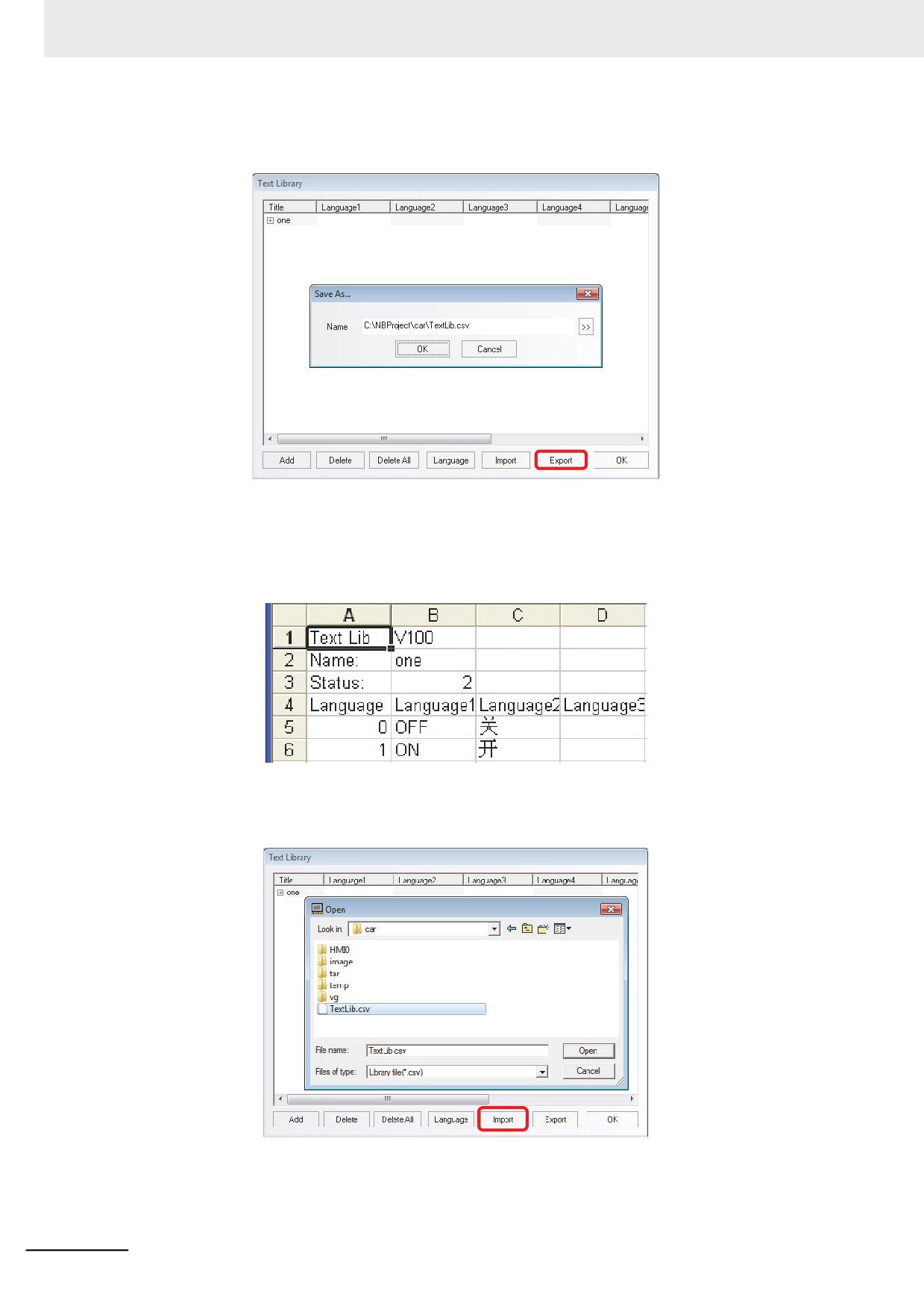
Text Library has the functions of importing & exporting the registered text in CSV format.
Exporting the registered text to the Text Library to the one in CSV format allows edition by the
spreadsheet software. Also importing the edited file can be taken in the NB-Designer.
3-241
3 Functions of NB-Designer
z Export Text Library
(1) The following dialog box will pop up after “Export” is clicked.
(2) Click [OK] to export the file. In order to change the destination to save the file and the
filename, click [>>] and specify the destination to save the file to and the filename.
(3) If the exporting is completed, the message saying “The file is exported successfully!” will be
pop up.
The opened export file in .csv format is as shown below.
z Import Text Library
(1) The following dialog box will pop up after “Import” is clicked.
(2) After confirming the CSV file supposed to be imported is not opened by other software,
select the CSV file and click [Open].
(3) If “Import file successfully” pops up, it means the import is successful.
3-242
3 Functions of NB-Designer
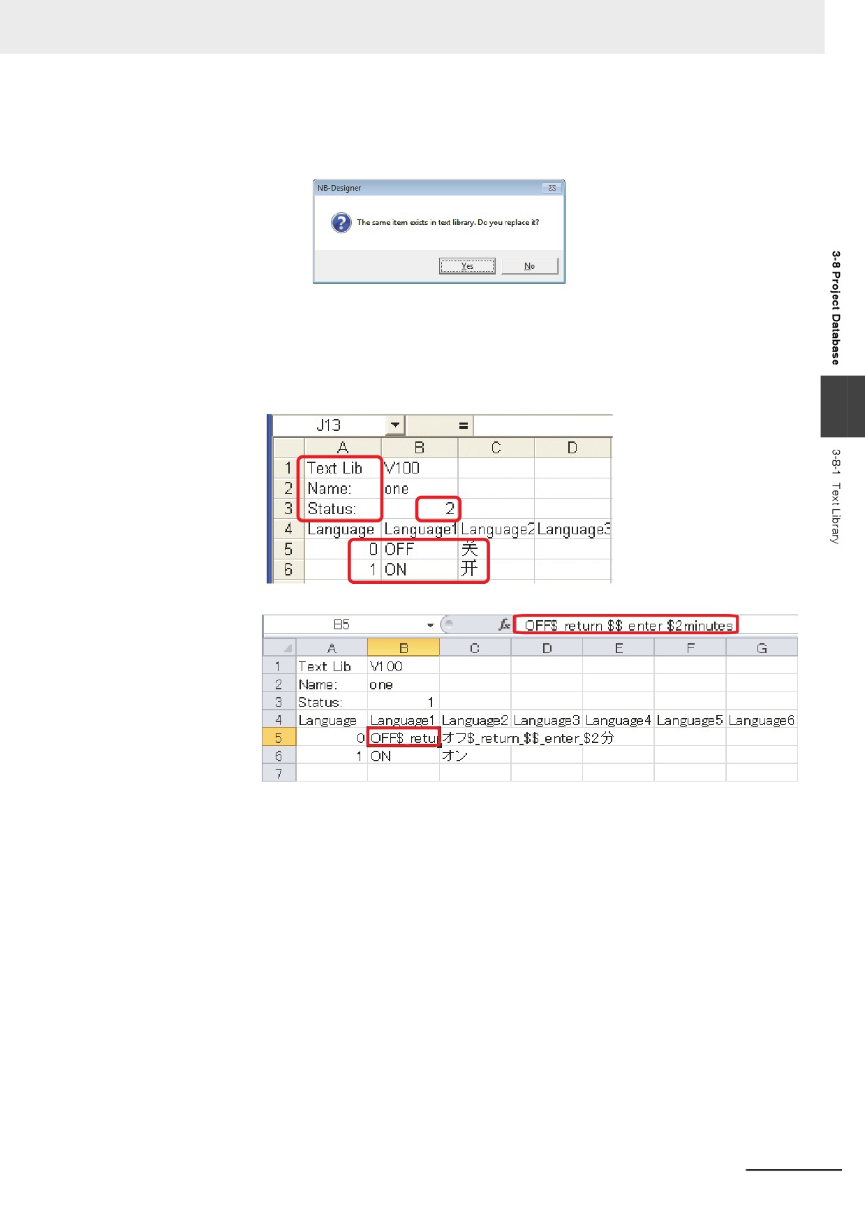
(4) If the imported file in .csv format has the items having the same name with that in the
existing Text Library of the system, the selection dialog box will pop up.
In this case, you can select “Yes” or “No” according to the circumstances.
z Notes for Import & Export
(1) The text strings such as “Text Lib”, ”Name” and “Status” included in the .csv file can’t be
changed, otherwise import will be impossible. Meanwhile, the value of “Status” must be
consistent with the actual status lines, as shown below, i.e. when “Status” is 2, the two
statuses contained in the text can only be “0” and “1”.
3
(2) If the line-break exists in the contents of Text Library, the exported file is shown as below.
If line-break is needed in spreadsheet software file, it just needs to input
“$_return_$$_enter_$”.
(3) Even after editing the CSV file by spreadsheet software, select “Unicode Text (*.txt)” for
[Type of Document] to save the file and then quit the used application and finally rename
the filename extension to .csv. The other file format cannot be recognized as available file
to import.
(4) The “Import” & “Export” are only applicable to the whole Text Library rather than the single
text item contained in the Text Library.
3-243
3 Functions of NB-Designer
5
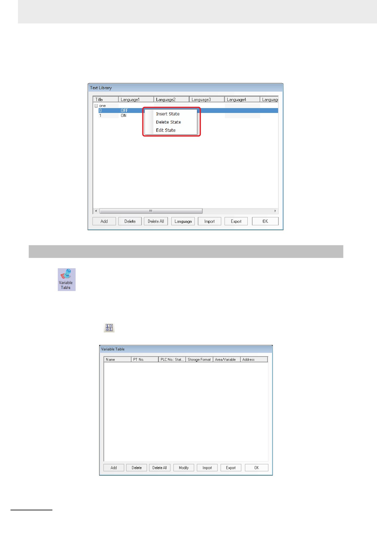
Change of State Number of Text Library
The change method of states number of Text Library is to select one state and right-click the
mouse, as shown below.
3-8-2
Variable Table
Variable Table is a useful address logon library, which prevents the inconvenience resulting
from repeated input of address, thus saving a lot of time. Check the [Use Variable] check box in setting
items for each component to use the address which was registered to the Variable Table with the
settings for each component.
1
Clicking
icon or entering [Variable Table] in the [Project Database] allows Variable Table
to pop up.
3-244
3 Functions of NB-Designer
2
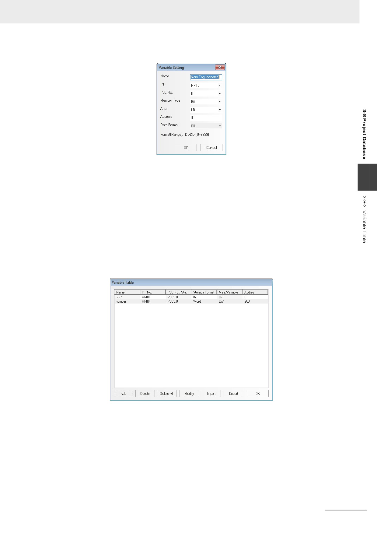
Click “Add” to make the following small dialog box pop up.
Name: Inputs the name of this variable.
PT: Selects the No. of PT corresponding to this variable.
3
PLC No. : Selects the No. of PLC corresponding to this variable.
Memory Type: Selects the memory type corresponding to this address from “Bit” or “Word”.
Area: Selects the area corresponding to this variable from “the internal memory of the PT” and
“the memory of the PLC”.
Address: Specify the address corresponding to the adding address.
Data Format: Select the data format of the adding address from “BIN” or “BCD”.
Format (Range): Displays the address format (the address range) of this variable.
3
Input the above-mentioned items respectively, and click “OK”, then the variable will appear in
the library.
3-245
3 Functions of NB-Designer
4
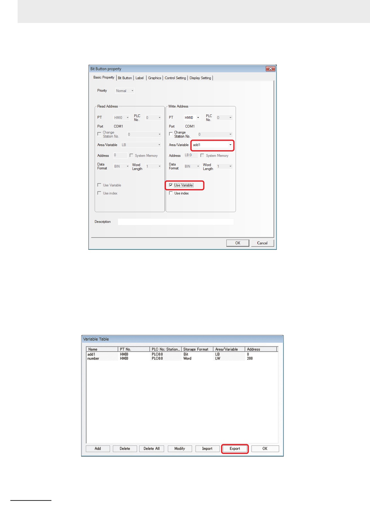
Later you can use it in the other places, as shown below.
Note 1
The addresses having been logged in the Variable Table can’t be changed in the other places, that’s to
say, they can only be used. If they are needed to be changed, you just need to enter the Variable Table
dialog box to change the address.
2
Note the following points when using the Variable.
The Variable specified [Bit] for the [Memory Type] can be allocated only to the bit state component. Also
the Variable specified [Word] for the [Memory Type] can be allocated only to the word state component.
5
Importing/Exporting a Variable Table
You can save variable information as a CSV file by pressing the [Export] button.
3-246
3 Functions of NB-Designer
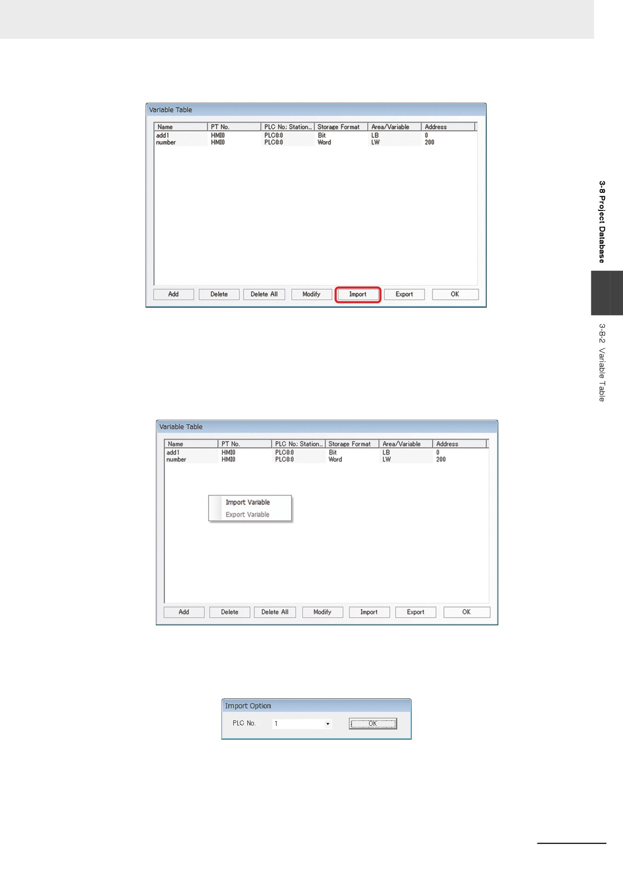
Press [Import] to import the variable information from a CSV file.
3
6
Importing Variables of NJ and NX Series
Variables of NJ and NX series can be imported to a variable table.
(1) Click [Tools] - [Export Global Variables] - [CX-Designer] under the Sysmac Studio Menu to
export the information about variables of NJ and NX series to Clipboard.
(2) Right-click on the Variable Table window. Select [Import Variable] to load the variable
information exported to the Clipboard *1.
*1 Importing variables is allowed only when you are using Omron Host that executes Ethernet com-
munication.
(3) A window to select a host appears after importing variables. Select the host, an import
destination.
3-247
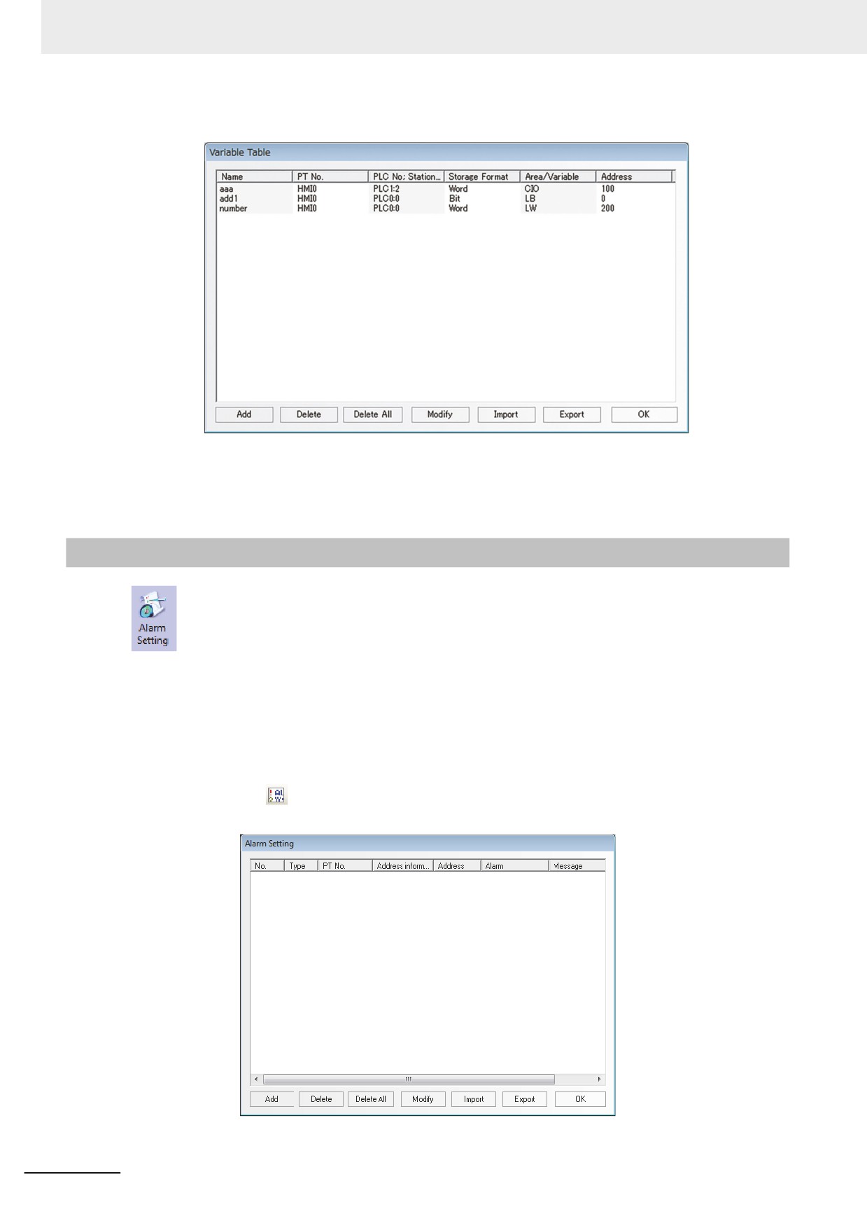
3 Functions of NB-Designer
(4) Click [OK] to import the variables of NJ and NX series.
Note You can import only variables to which AT Specification address is allocated in Sysmac Studio.
Variable types to be imported are: BOOL, UINT/ INT/ WORD, UDINT/ DINT/ DWORD/ REAL.
On NB-Designer, BOOL variable is replaced to Bit, UINT/ INT/ WORD are replaced to Word, and UDINT/
DINT/ DWORD/ REAL are replaced to DWORD.
DWORD variable cannot be edited on NB-Designer.
3-8-3
Alarm Setting
To display the information on the Alarm component or Alarm Display component, the logon in
the list of [Alarm Setting] database is needed. One bit address can control whether one piece of
information will be displayed or not. If the logged bit address is triggered (ON or OFF), the related
information will be displayed on the Alarm component. (This component is only responsible for the
logon of Alarm Setting, and the display needs to be done by “Alarm” component.)
z Add/Modify Alarm Setting
1
Clicking the
icon located in the Database Toolbar or the “Alarm Setting” in the “Project
Database” allows an “Alarm Setting” dialog box to pop up.
3-248
3 Functions of NB-Designer
2
Select the [Add] button to add the setting or select the [Modify] button to modify the existing
setting.
3
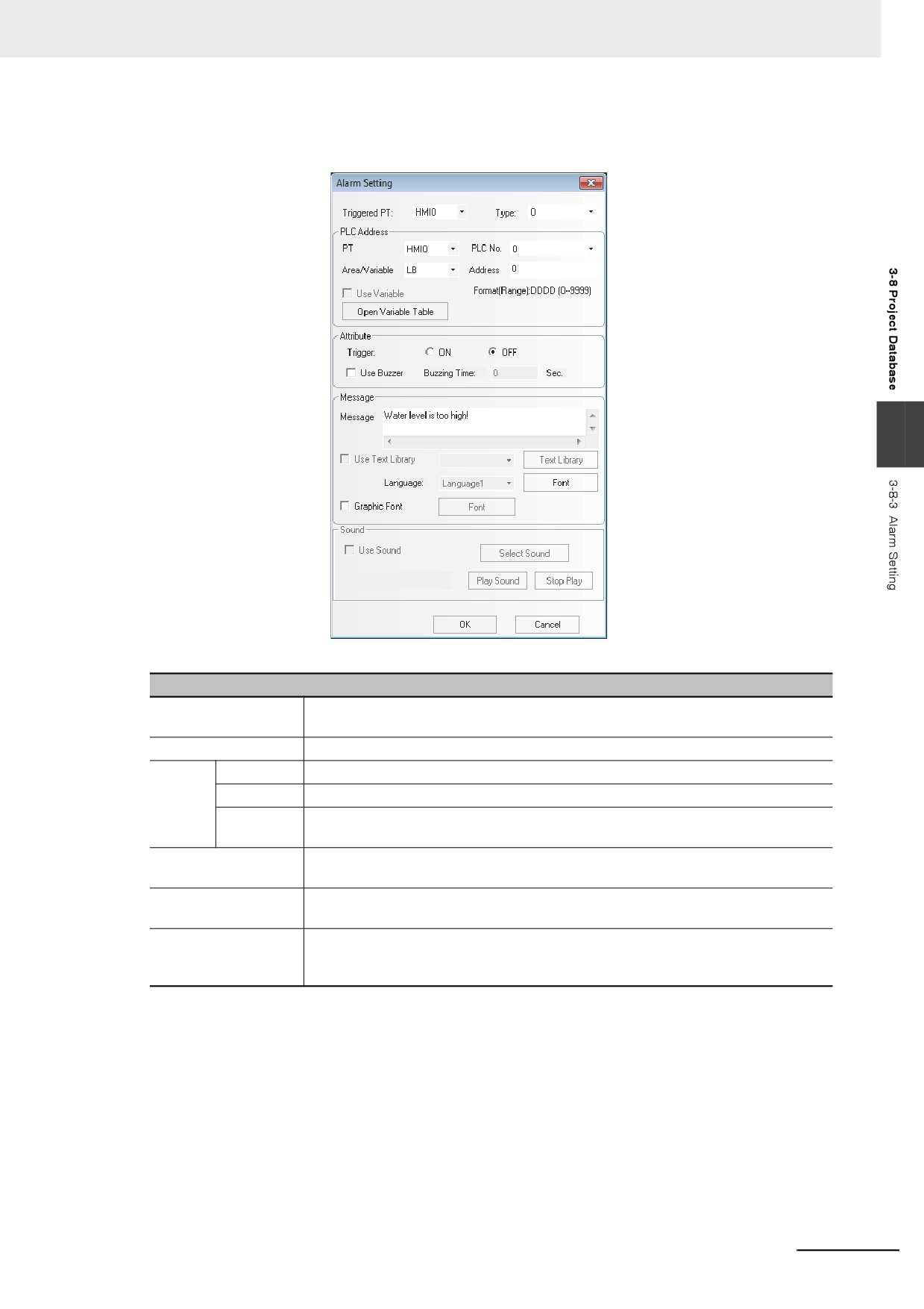
Descriptions of Alarm Information Property
Triggered PT
Select one PT to specify the Alarm Setting when multiple PTs were registered to the
project.
PLC Address
Specifies the bit address of the memory that triggers the read of the alarm.
Property
ON
When the specified bit address is ON, one piece of alarm information is generated.
OFF
When the specified bit address is OFF, one piece of alarm information is generated.
Use Buzzer
When the alarm information is triggered, the buzzer will be enabled. The Buzzing
Time can be set with the unit of “second”.
Message
Inputs the contents of alarm setting to be displayed. Clicking [Font] can set the Font
and the related attributes.
Use Text Library
Determines whether to use the contents logged in the Text Library. For the use of
the Library, refer to [3-8-1 Text Library].
Language
When using multi-language Text Library, you can select the language here and click
“Font” to set the font attributes corresponding to text in each kind of language
respectively.
3-249
3 Functions of NB-Designer
3
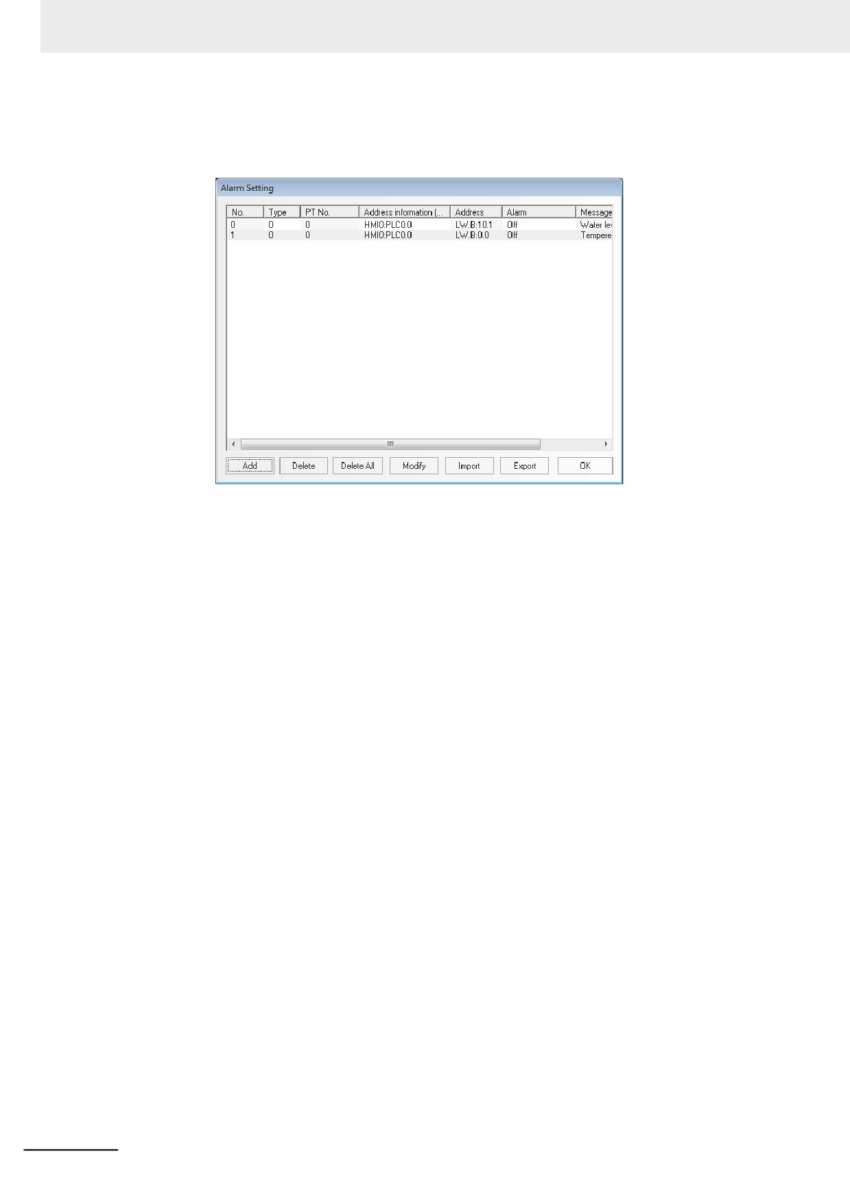
Press the [OK] button to make the alarm setting displayed in the list. After the alarm setting is
logged, the existed alarm setting can be edited by [Delete] or modified by [Modify] buttons.
Press the [OK] button to complete the logon of the alarm setting.
Note In order to perform the communications effectively, specifying the continuous address is recommended as
read address of the alarm information. For example, when you specify the continuous addresses from M100
to M199, whole the addresses from M100 to M199 can be read in the communications only once.
z Event/Alarm Type
The Event/Alarm is divided into 256 types, i.e. 0 to 255, in the NB-Designer.
Event, Alarm and Alarm Display can restrict the types of the displayed events respectively. For
example, if the display type of “Event Component” is specified from 0 to 3 in the [Event Setting] tab
of Event Properties, only the contents of event ranging from Type 0 to Type 3 will be displayed.
This option is used to select the type of the alarm and event displayed currently.
3-250
3 Functions of NB-Designer
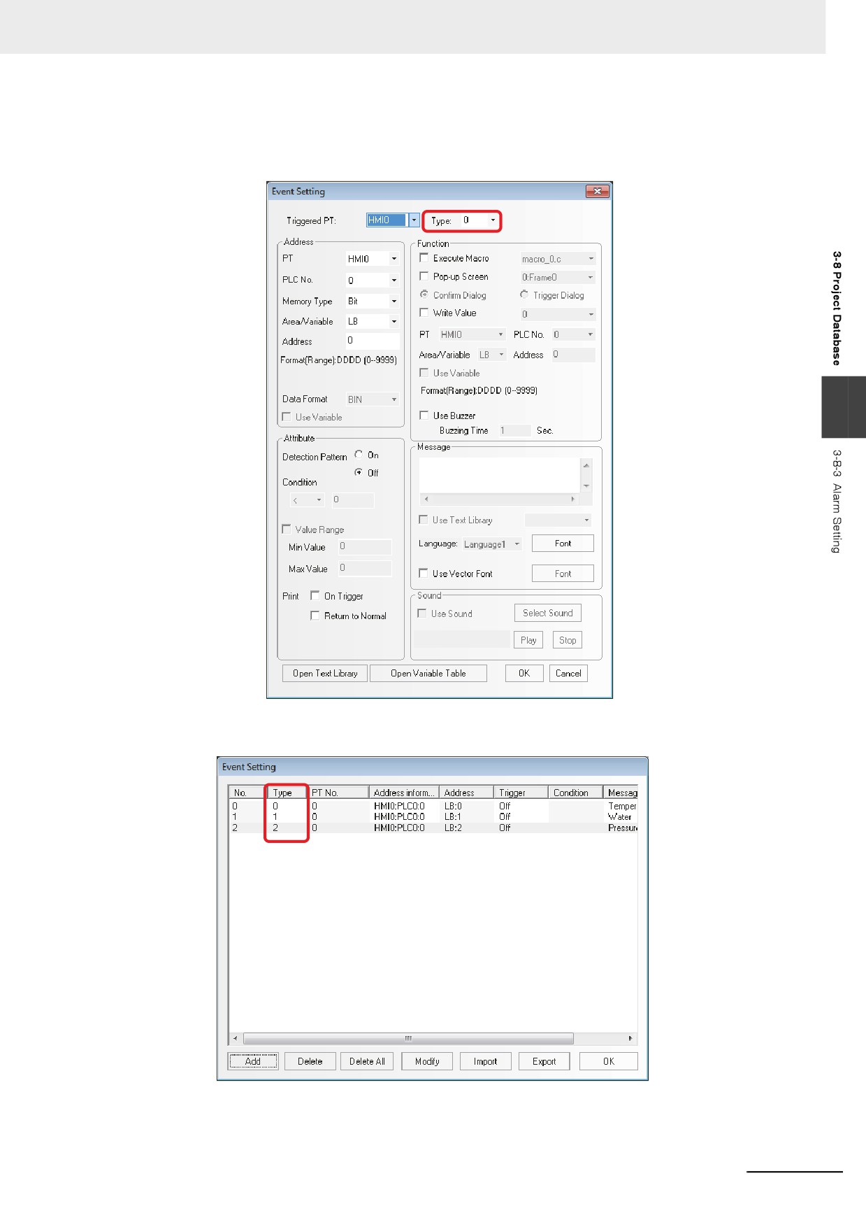
Example: To create an event log with the type of each event being different.
(1) Click the [Event Setting] of the [Project Database] and open the [Event Setting] dialog box.
Click the [Add] and add a new event setting as below.
3
(2) Create the event triggered by the LB1 and LB2 in the same procedure as the LB0's. The
Type of the LB1 is specified to 1 and the Type of the LB2 is specified to 2.
3-251
3 Functions of NB-Designer
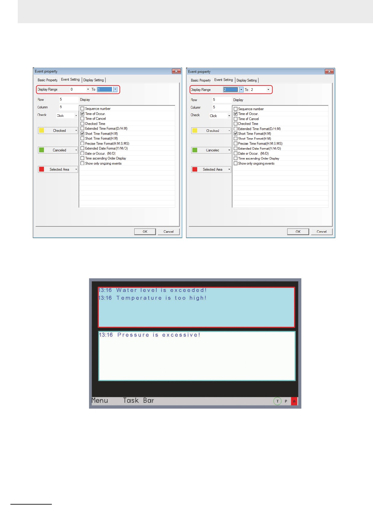
(3) Place two Event components with the addresses of LW0 in the Edit Window and the
settings are as shown below.
Event display component 1
Event display component 2
(4) When the offline test is performed, the event with the format (type) 0 of ON and the trigger
for the LB0 and the format (type) 1 of ON and the trigger for the LB1 is displayed in Event
component 1 and the other event with the format (type) of ON and the trigger for the LB2 is
displayed in Event component 2.
3-252
3 Functions of NB-Designer
3-8-4
Event Setting
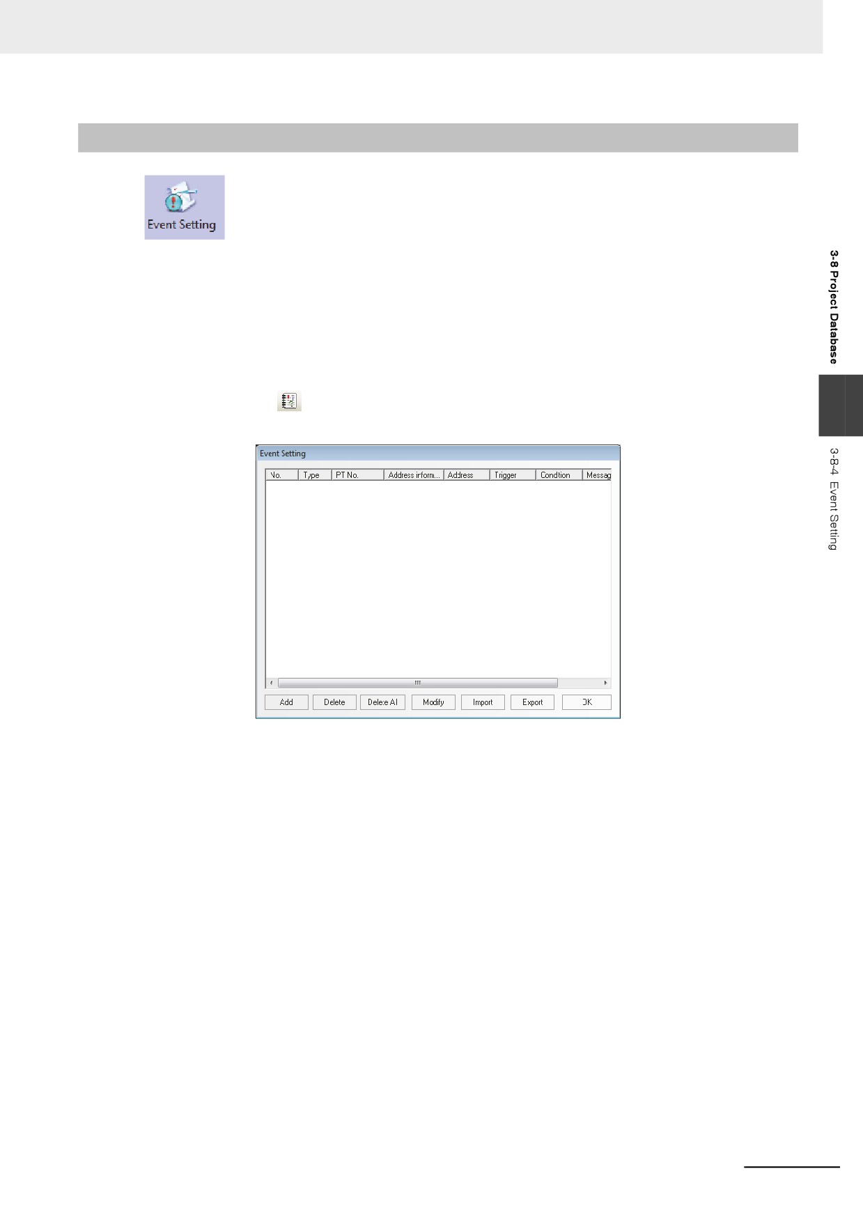
The information logged in Event component will be displayed in the Event component. To
display the information in the Event component, the information must be logged in the [Event Setting]
database in advance. One bit or word address controls one piece of information. When the logged bit or
word address is triggered (i.e. It is ON/OFF or the restricted value is triggered.), the corresponding
information will be displayed in the Event component. (This component is only responsible for the event
log, and the display needs to be done by “Event” component.)
z Process of Adding/Modifying Event Setting
1
Clicking the
icon located in Database Toolbar or “Event Setting” in the “Project
3
Database” allow “Event Setting” dialog box pops up.
3-253
3 Functions of NB-Designer
2
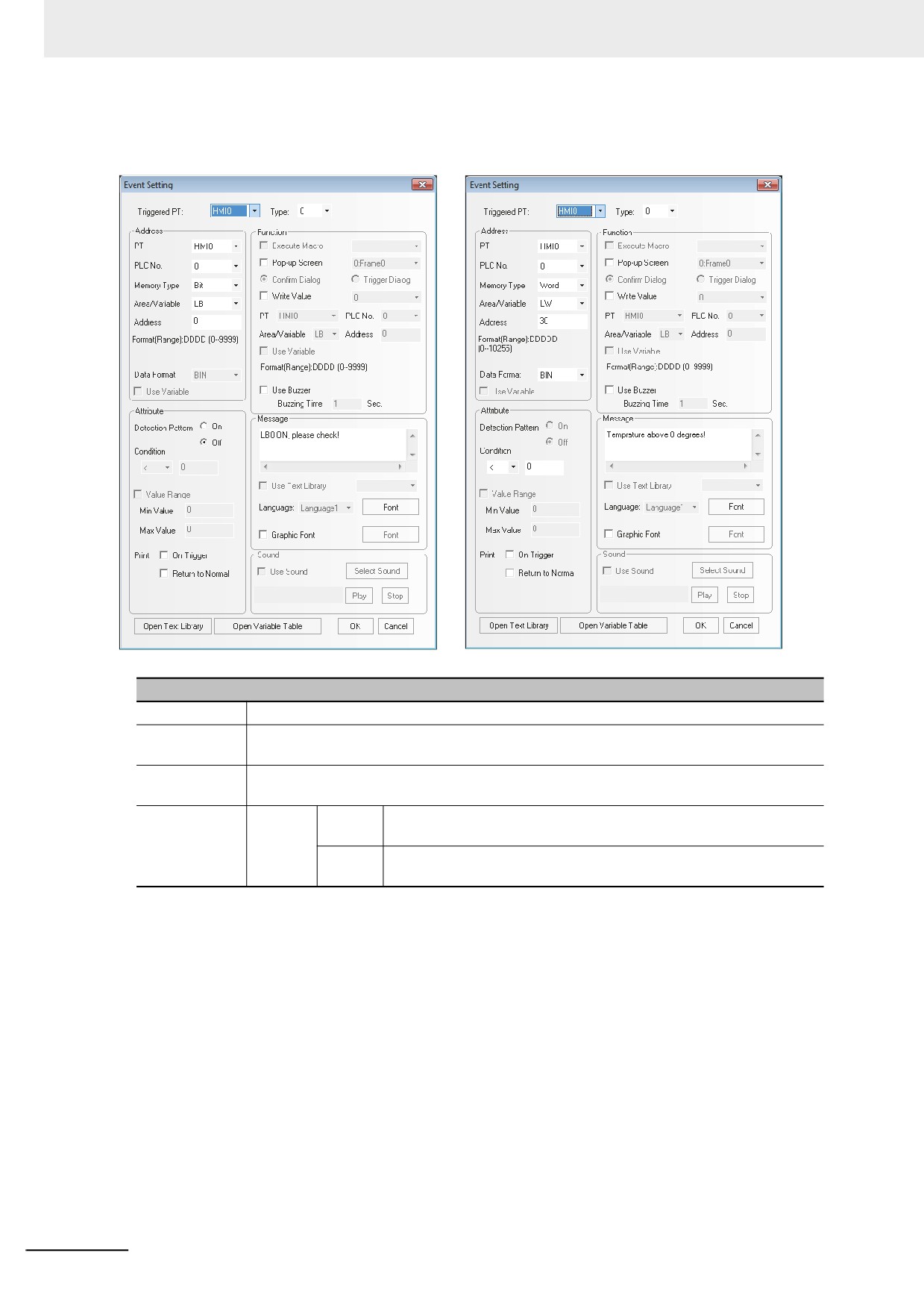
Select the [Add] button to add the information or select the [Modify] button to modify the
existing information.
Descriptions of Event Information Properties
Triggered PT
Select one PT to specify the Event Setting when multiple PTs were registered to the project.
Type
Classifies the events and the available type is from 0 to 255. [Event Display] tab of the Event
Display component can restrict the displayed event type.
Address
Specify the register working as the trigger of the event. The type of memory can be changed
into “Bit” or “Word” through “Data Type”.
Attribute
Bit
ON
When the state of the bit address is turn from OFF to ON, one
specified event record will be displayed.
OFF
When the state of the bit address is turn from ON to OFF, one
specified event record will be displayed.
3-254
3 Functions of NB-Designer
Descriptions of Event Information Properties
Attribute
Word
<
When the value of the specified word address is less than the
specified value, one specified event record will be displayed.
>
When the value of the specified word address is greater than the
specified value, one specified event record will be displayed.
==
When the value of the specified word address is equal to the specified
value, one specified event record will be displayed.
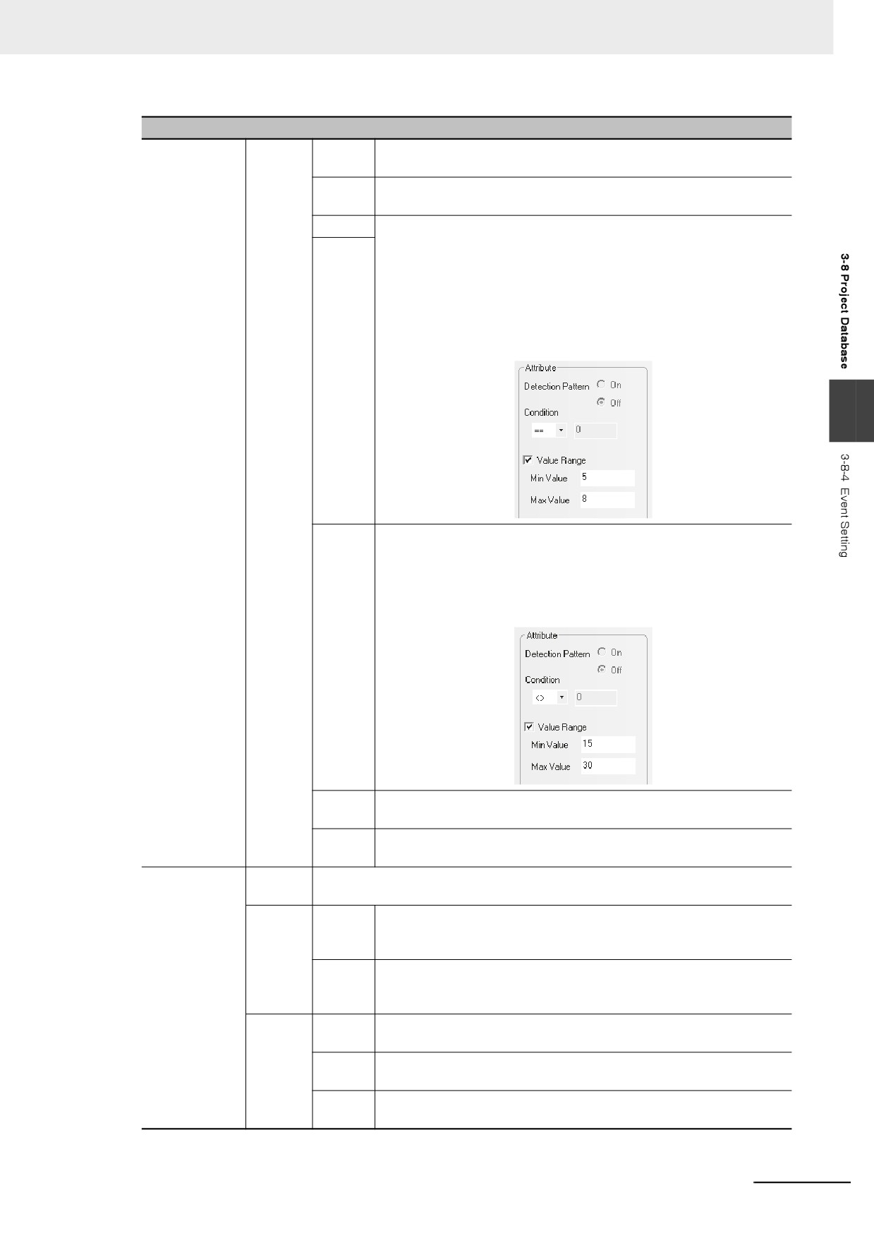
[Value Range] When the value of the specified word address is within
the specified range, one event record will be generated. As shown
below, check “Value Range” with “Min Value” & “Max Value” set to “5”
and “10” respectively, if the value which is represented as N, of the
specified word address is larger than 5 and smaller than 10, one
specified event record will be displayed.
3
< >
When the value of the specified word address is not equal to the
specified value, one specified event record will be displayed.
As shown below, check “Value Range” with “Min Value” & “Max
Value” set to “15” and “30” respectively, if the value which is
represented as N, of the specified word address is less than 15 or
larger than 30, one specified event record will be displayed.
< =
When the value of the specified word address is less than or equal to
the specified value, one specified event record will be displayed.
> =
When the value of the specified word address is greater than or equal
to the specified value, one specified event record will be displayed.
Function
Execute
When event occurs, the selected Macro will be executed. *
Macro
Pop-up
Confirm
Touching the event information displayed in the event component, the
Screen
Dialog
specified screen will pop up. And it needs to use the “Close Screen”
function of the Function Key to close this Pop-up Screen.
Trigger
The specified screen will pop up when the event occurs. And it needs
Dialog
to use the “Close Screen” function of the Function Key to close this
Pop-up Screen.
Write
0
When the event log occurs, the state of the specified bit memory will
Value
be set to “0”.
1
When the event log occurs, the state of the specified bit memory will
be set to “1”.
Not
When the event log occurs, the state of the specified bit memory will
be reversed.
3-255

3 Functions of NB-Designer
Descriptions of Event Information Properties
Message
Inputs the contents of event or event display to be displayed. Clicking [Font] can set the
Font Type and the related attributes.
Use Text
Determines whether to use the contents logged in the Text Library.
Library
Language
When using multi-language Text Library, you can select the language displayed
as the event information here and click “Font” to set the font Property
corresponding to text in each kind of language respectively.
TIP: The data and others stored in internal memory LW can be displayed in the event
information.
The available formats are follows:
•
%h:mm:s#:
The Time of Occur. is indicated.
•
%y:mm:d#:
The Date of Occur. is indicated.
•
%nnfmd:
“%” represents the start symbol, “nn” represents the addresses of the internal memory LW
from 00 to 99.
“f” represents that the displayed number includes the decimal part.
“m” represents the digit of the decimal digit.
“d” represents the end symbol.
If “%nnd” is entered, the value excluded the digit of decimal digit will be displayed. For
example, if you want to display the value stored in LW20 with one decimal digit, enter
“%20f1d”. If the stored value in the PLC memory should be displayed, transferred it to
internal memory LW to display it.
Use Buzzer
When the event is triggered, the buzzer will be enabled. The Buzzing Time can be set with
the unit of “second”.
Open Text
Opens the text library editing dialog box.
Library
Open Variable
Open the variable editing dialog box.
Table
* Please refer to 3-9-3 Macro Triggering (Page 3-273).
3
Clicking [OK] allows the specified event setting added in the List of the [Event Setting] dialog
box. The registered event setting can be deleted by [Delete] button or modified by [Modify]
button. Click [OK] button to finish the registration of the event setting.
Note In order to perform the communications effectively, specifying the continuous address is recommended
as read address of the Event Setting. For example, when you specify the continuous addresses from
M100 to M199, whole the addresses from M100 to M199 can be read in the communications only once.
3-256
3 Functions of NB-Designer
3-8-5
PLC Control
When the corresponding control is triggered, PLC Control component can activate one
specific operation.
PLC Control component is a powerful component group, which can realize a large variety of functions
because it is more powerful than the general component. And its functions are as follows:
(1) Switch Screens: Changes the current screen.
(2) Write data (current base screen number) into PLC: Transfers the current Screen No. to the PLC.
(3) General-purpose PLC control: Realizes the data transmission between the PLC address and
LW/RW.
(4) Backlight Off: Turns off the backlight.
3
(5) Backlight Off (Write Back): Turn OFF the back light. (The control bit will be reset.)
(6) Execute Macro: Executes the corresponding Macro number when the condition is met.
(7) Backlight On: Turns on the backlight.
(8) Backlight On (Write Back): Turn ON the back light. (The control bit will be reset.)
(9) General PLC Control (Expansion)
(10) Change Screen (Ignore screen 0)
Note Do not specify the same address in the functions of Switch Screens, Change Screen (Ignore screen 0), and
Write data (current base screen number) into PLC.
z Process of creating one PLC Control
1
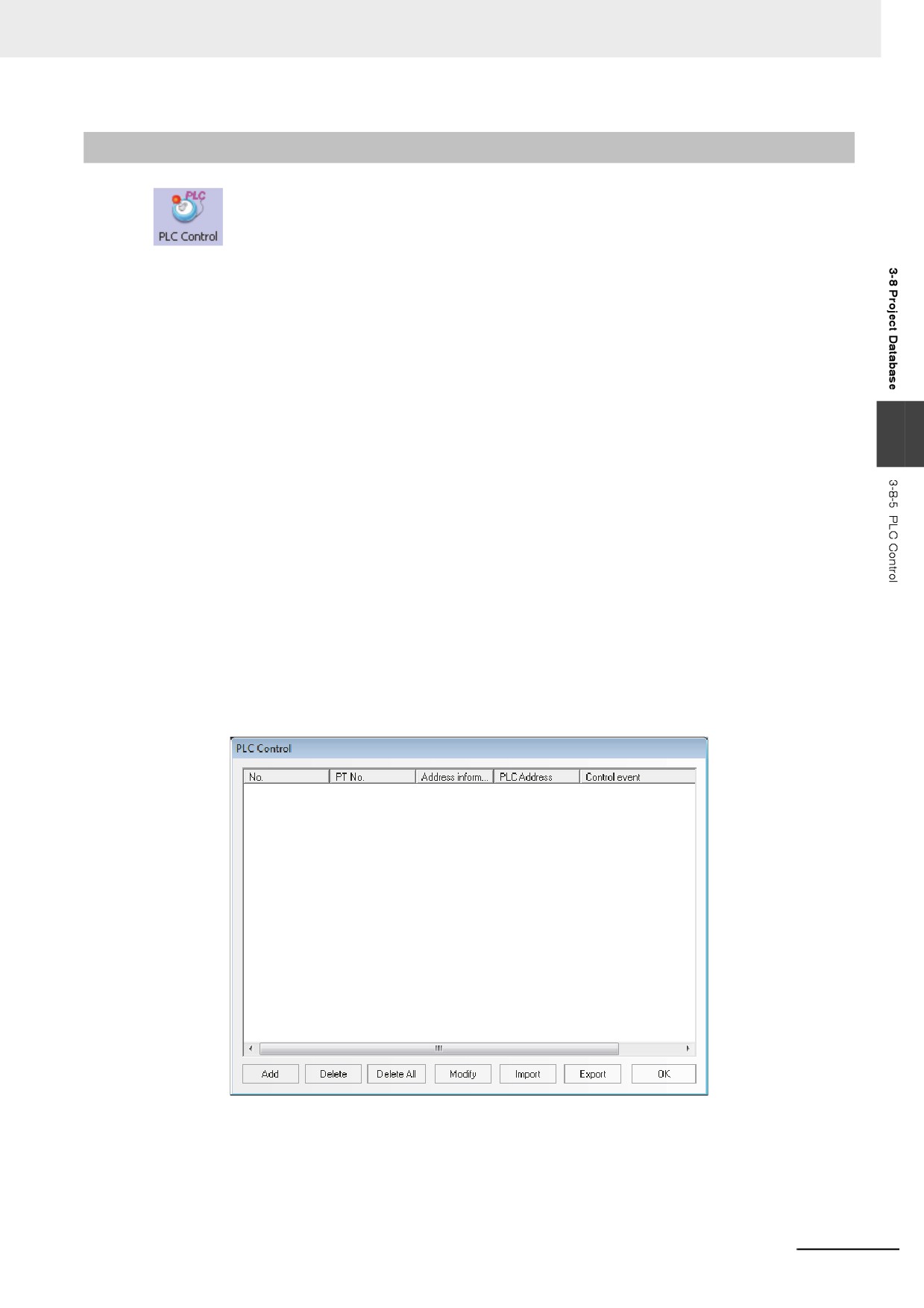
Press the PLC Control icon to make the list of PLC Control pop up.
2
Press “Add” button to create a new PLC Control or press “Modify” and “Delete” buttons to
modify the PLC Control and delete the selected setting respectively.
3-257
3 Functions of NB-Designer
3
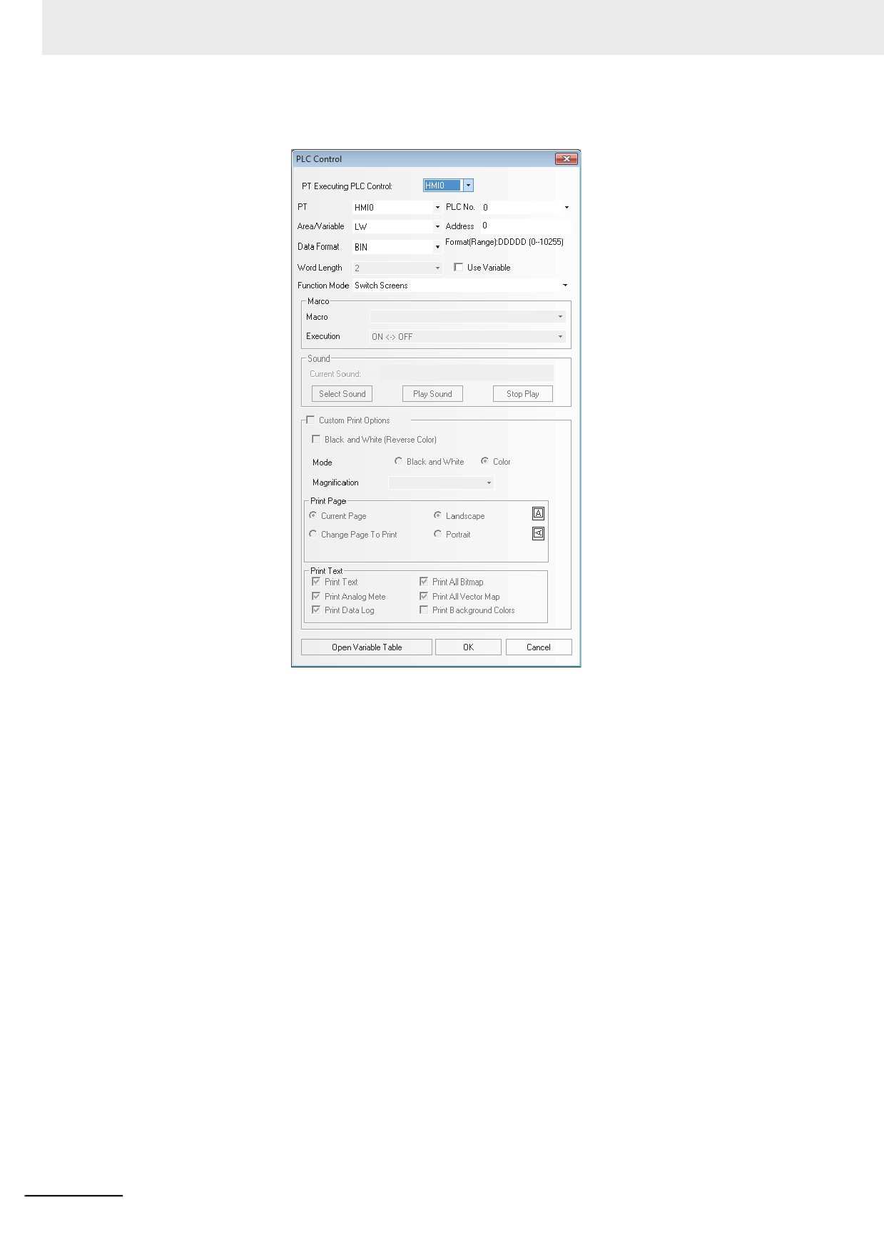
Specify the options displayed in the PLC Control dialog box correctly.
Area/Variable: Specifies the Area/Variable of the devices performing the PLC control
operations.
Address: Specifies the addresses of the devices performing the PLC control operations.
Data Format: Includes BIN or BCD.
Function Mode: Specifies the operation types of the setting. There are 12 types available, and
their functions will be described later in details.
Macro: Sets the No. of Macro program to be executed when the Function is “Execute Macro”.
4
Press the “OK” button to exit from the PLC Control dialog box.
5
Repress the “OK” button to exit from the list of PLC Control.
3-258
3 Functions of NB-Designer
z Function Mode
1
Switch Screens
This operation needs 2 consecutive word addresses. When the [Read Address] is switched to
a valid screen No., the current screen will be closed and the specified screen will appear.
Specify the number in the destination screen in the [Read Address]. The number after
switching will be written in [Read Address + 1]
Read Address
For screen switching control
Read Address + 1
No. of the destination screen
For example, set the address to “DM0”, Data Format to “BCD” and the current screen to Frame
0. If DM0 is changed to 10, the current screen will be switched to Frame 10, and 10 will be
returned to DM1.
Note Each time the [Change Screen] Function Key is pressed, the current screens is closed and the
destination screen is displayed. The function of [Switch Screens] of the PLC control is similar to the
3
[Change Screen] function of the Function Key. Their difference is the respect whether function is operated
by touching the screen or it is performed by the PLC memory control. When the value of Read Address is
modified to an available screen No., the current screen will be closed and the screen specified with the
Read Address will be displayed. Then the content of the Read Address in written in the Read Address +
1. This operations can be executed only when the Read Address is modified.
2
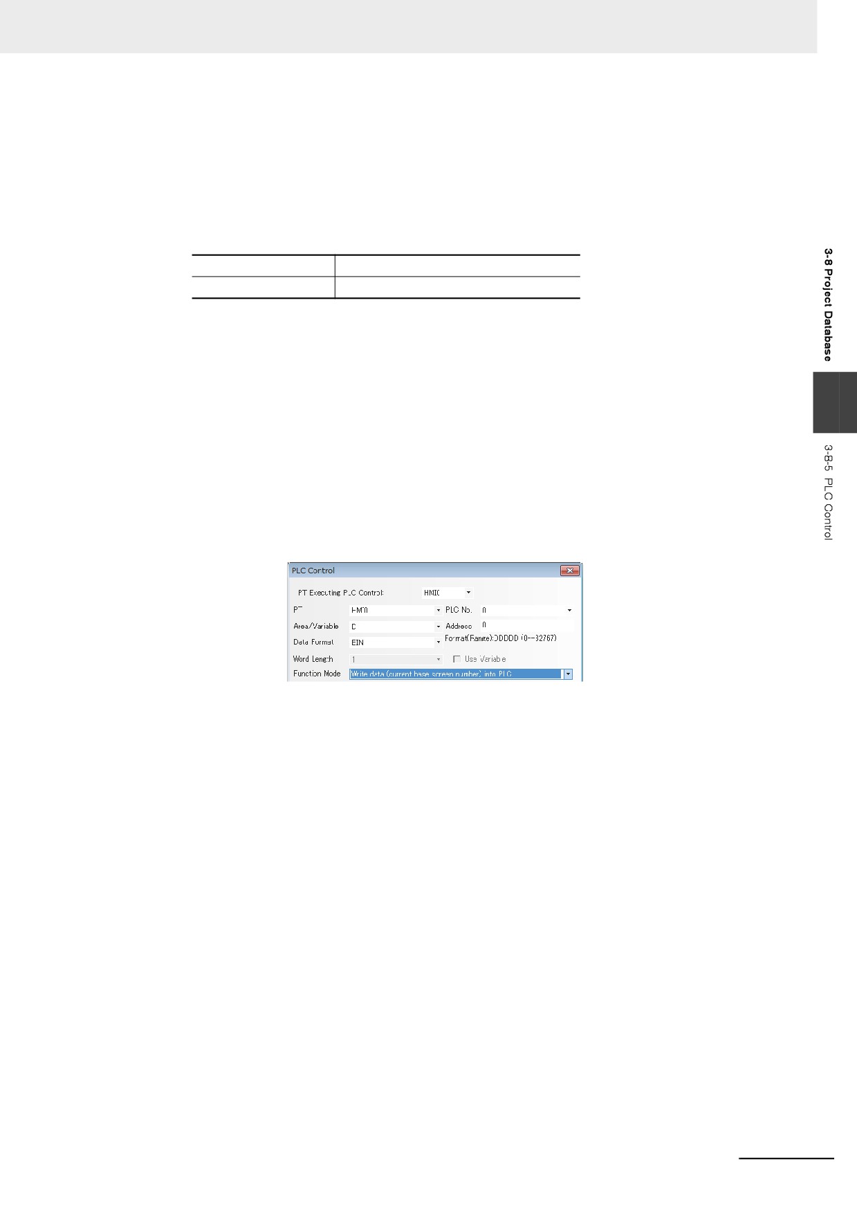
Write Data (Current Base Screen No.) into PLC
The number of the base screen currently displayed will be notified to the PLC.
When there is a PLC Control with the settings shown as above, word address DM0 will store
the No. of the current base screen.
3
General PLC Control
The data transmission between the PLC and the PT can be controlled.
It can be divided into 4 types according to the direction of data transmission:
(a) PLC˘ RW (Recipe Data Memory), type code 1.
(b) PLC˘ LW (Local Data memory of PT), type code 2.
(c) RW (Recipe Data memory)˘ PLC, type code 3.
(d) LW (Local Data memory of PT)˘ PLC, type code 4.
The specific instructions are as follows:
Select “General PLC Control” as “Control Type” in PLC Control setting dialog box, and select
the data area and the address of the data transmitted by the [Read Address]. Please note that
the unit must be “word”, and the system automatically allocate 4 continuous addresses, which
are used as the controlling addresses of the data transmission. And the specific meanings and
usage methods are as follows:
(1) Read Address: Select the 4 types of execution type codes. When new value is written to the
memory, the system execute the corresponding transmission function. After the
transmission is detected, the memory will be reset to 0.
(2) Read Address + 1: Specify the size of the data transmitted. The number of the word
specified at this moment will be transmitted.
3-259
3 Functions of NB-Designer
(3) Read Address + 2: Specify the offset of the transmitted data address of the PLC side. The
offset is specified from the address of [Specified Read Address + 4].
For example, if the Read Address set in the PLC General Control is DM100, and the data
contained in memory DM102 is 4. The starting address of the transmitted PLC data is
DM108 = [(100 + 4) + 4].
(4) Read Address + 3 : Specify the offset of the transmitted data address at the sides of local
memory (LW) of the PT or Recipe data memory (RW)
In the example listed above, if the data contained in DM103 is 100, the starting address of
the transmitted PT data operated during the transmission is RW (LW)100=(0 + 100).
Here is the procedure which uses the PLC control, to transmit the data includes 30 words
starting from DM100, to the data block of the same size starting from RW200 in the Recipe
Data memory of the PLC.
(1) Firstly, specify the PLC control component set with [General-purpose PLC Control] for the
control select and DM10 for [Read Address].
(2) Secondly, specify the size of the data and the offset address of the controlling data. DM11
is specified to 30 (it means the number of transmitted words is 30 words.) DM12 is specified
to 86 (the starting address is DM100=(10+4+86) in the PLC and DM13 is specified to 200
(the destination address is RW200=(0+200), respectively.
(3) Finally, specifying the execute type code according to the direction of the data transmission
allows the data transmission. If DM10 is specified to 1, the number of the specified data will
be transmitted from the starting address of the PLC to the Recipe Data memory of the PT.
If DM10 is specified to 3, the direction to transmit the data will be reversed.
The other transmission to two destinations are performed in the same procedure as above.
4
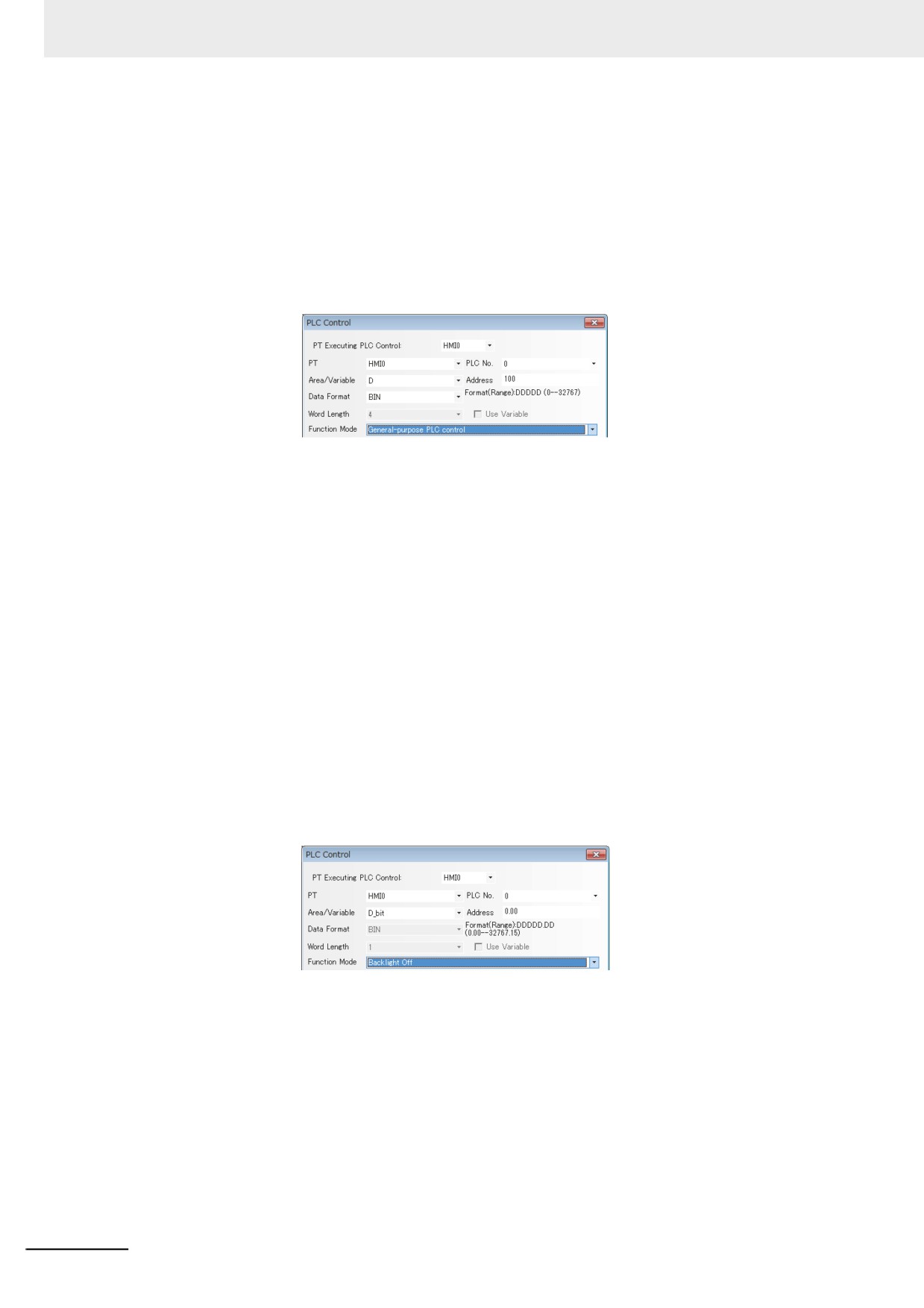
Backlight Off
This operation uses one bit address to control the closing of the backlight, and when the bit
address is ON, the backlight will be closed.
In the settings shown as above, when D_bit0.00 is ON, the backlight turns off. In this case,
when the user touches the PT, the backlight will automatically light on, and at this time the
D_bit0.00 is still ON. If the user touches the D_bit0.00 again, it will be turned OFF, thus
returning to the state before the backlight is closed.
3-260
3 Functions of NB-Designer
5
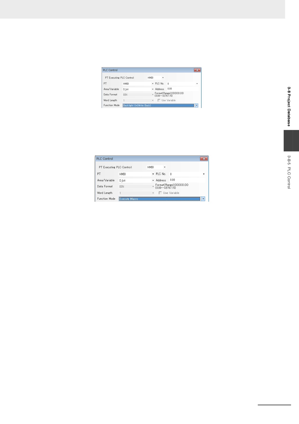
Backlight Off (Write Back)
The operation of this option is similar to [Backlight Off], but the address of this bit of PLC will be
cleared to 0 while as well as the back light turns Off and then the bit address turns ON.
In the settings shown as above, when D_bit0.00 turns ON, the backlight is OFF, and D_bit0.00
is automatically turned OFF. When the user touches the PT, the backlight turns ON and
D_bit0.00 remains OFF.
6
Execute Macro
3
When the state of the specified bit address is ON, the selected Macro ID will be triggered.
Area/Variable and Address: Refers to the address to trigger the Macro program execution.
The Macro program will be executed when this bit is 1, while not executed when this bit is 0.
Macro ID: Select a Macro to be executed.
Execute Method:
ON¯˘ OFF: When the specified bit turns OFF from ON or vice versa, the Macro will be
executed.
OFF˘ ON: When the specified bit turns ON from OFF, the Macro will be executed.
ON˘ OFF: When the specified bit turns OFF from ON, the Macro will be executed.
ON: When the specified bit is ON, the Macro will be executed.
OFF˘ ON, Reset: When the specified bit turns ON from OFF, the Macro will be executed and
the specified bit will be forced into OFF.
ON˘ OFF, Reset: When the specified bit turns OFF from ON, the Macro will be executed and
the specified bit will be forced into ON.
Note Only when the Macro is added within the project, this function is available. If the Macro code is
removed after specifying the “Execute Macro” in the Function Mode option the PLC Control dialog
box by the Function selection, the code is converted automatically to the Macro in the default. If the
Macro does not exist, [Macro] column is left to blank as the default.
3-261
3 Functions of NB-Designer
7
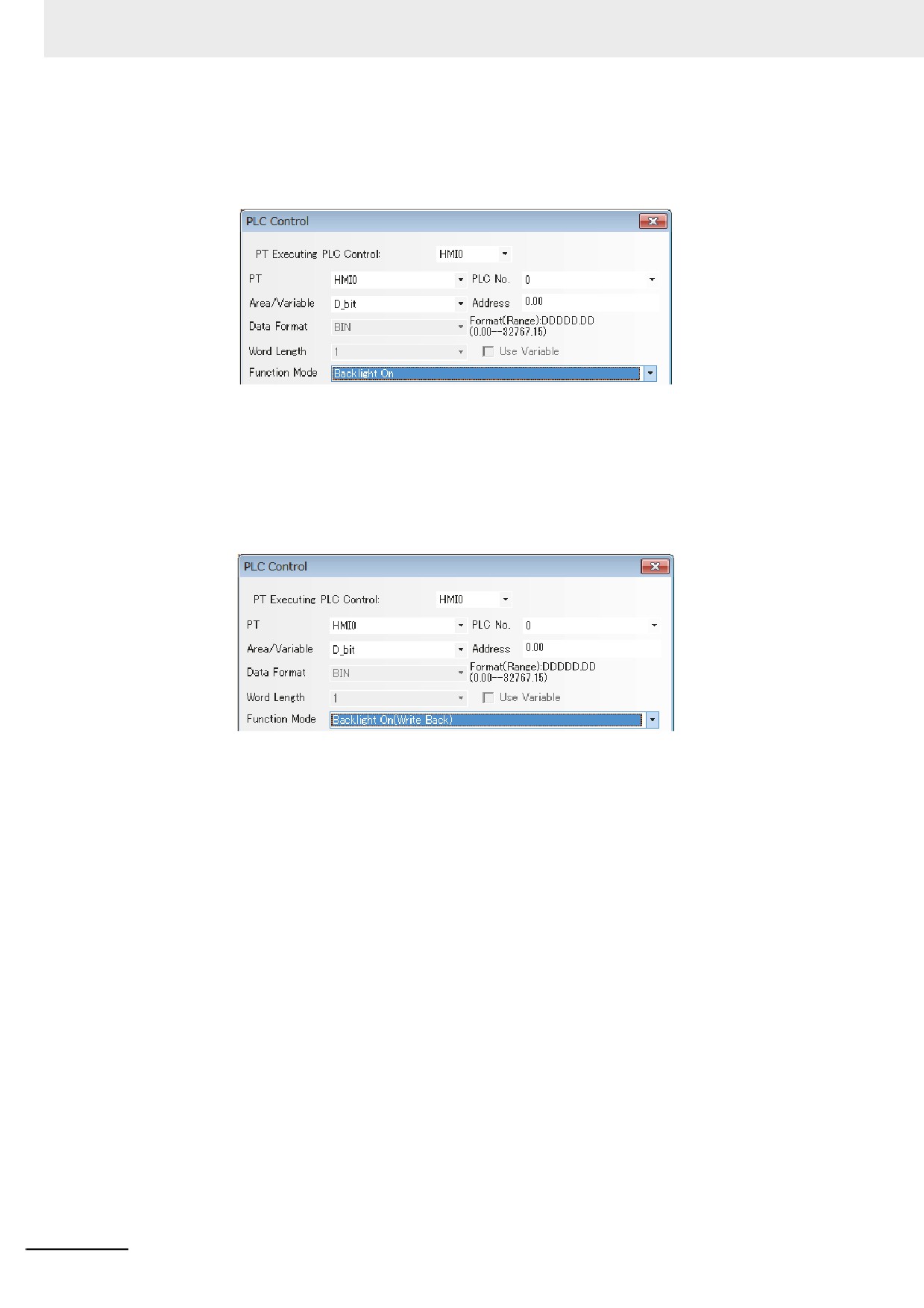
Backlight On
This operation uses one bit address to control the lighting of the backlight, and when the bit
address is ON, the backlight turns ON.
In the settings shown as above, when D_bit0.00 is ON, and the back light will turn ON. If the
user touches D_bit0.00 again, it will turn OFF, thus returning to the state before the backlight
lights on.
8
Backlight On (Write Back)
The operation of this option is similar to [Backlight On], but the address of this bit of PLC will be
cleared to OFF while the bit address turns ON.
In the settings shown as above, D_bit0.00 turns OFF automatically as well as the back light
turns ON when the D_bit0.00 turns ON.
3-262