OMRON NB-Designer OPERATION MANUAL (NB-series, 2020) - page 8
3 Functions of NB-Designer
Format Content
Descriptions
Date of Occur
The data format is displayed as Month/Date.
Time ascending Order
The event is displayed in the ascending order.
Display
Show only ongoing
Only the event that is trigged is displayed here. And the released event will not be
events
displayed in the Event list. If this option isn’t checked, the events occurred before
but return to normal will still be displayed in the event list unless the event list is
cleared.
Date of
Time of
Checked
Time of
Event
No.
Occur
Occur.
Time
Cancel
content
3
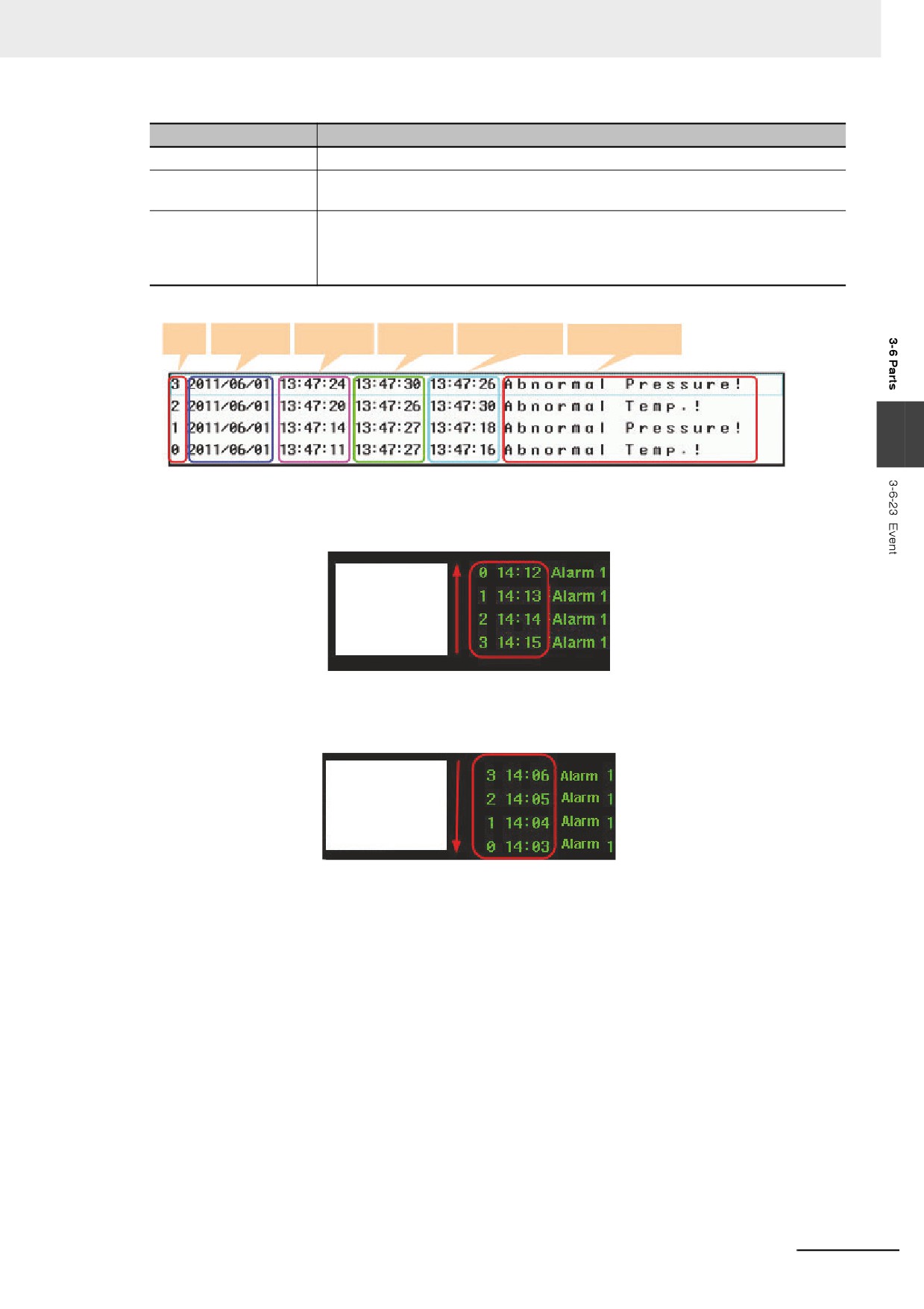
Time ascending Order Display: When this option is checked, the latest occurred event will be
displayed on the bottom and the event sequence No. and the
time will ascend from top to bottom, as shown below.
Ascending order
by time, new
trigger events
are displayed on
the following.
When this option is not checked, the event will be displayed in the descending order, i.e. the
latest occurred event will be displayed on the top, and event sequence No. and the time will
descend from top to bottom, as shown below.
Descending order
by time, new
trigger events are
displayed on the
top.
3
Press the [OK] button to complete the setup, and adjust the position and the size of the Event
component.
3-173
3 Functions of NB-Designer
z Example of Event
1
First create a new project and [Save] it.
2
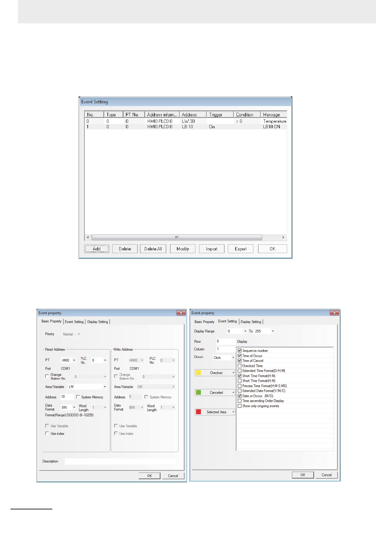
Add two events in the [Event Setting], as shown below.
Where, the 1st event is the pop-up screen 4 and the 2nd event is the pop-up screen 5.
3
Add one Indirect Screen in screen 0 of the newly created project and its [Read address] of LW5.
4
Add one Event component in screen 0, as shown below.
Place one Vector Graphics under the Event component to enhance the display effect.
3-174
3 Functions of NB-Designer
5
Add one Bit Switch to control the ON/OFF state of LB10.
6
Add one Text component with the content of “Increase water temperature”.
7
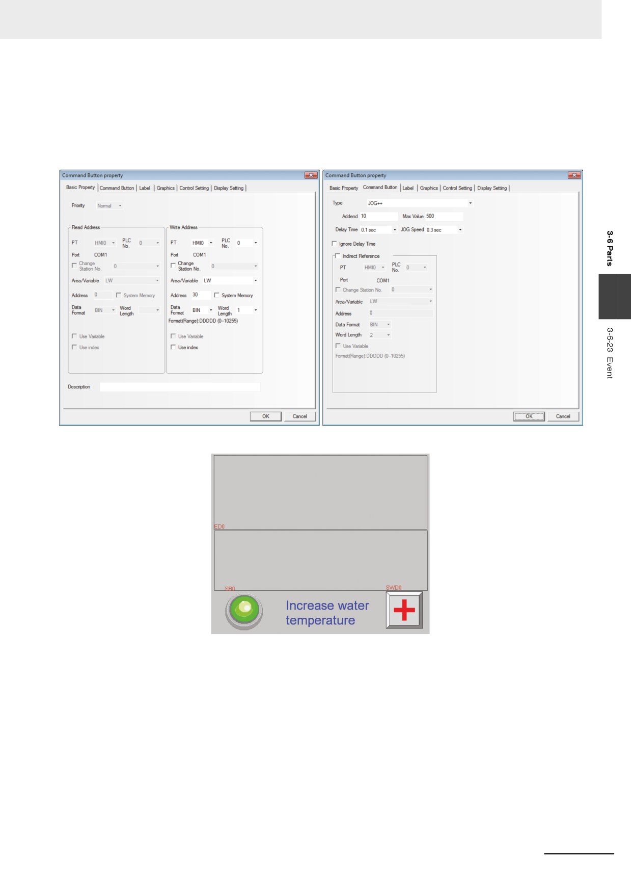
Add one Command Button component with the settings as shown below:
3
Finally, the screen 0 is shown as below:
3-175
3 Functions of NB-Designer
8
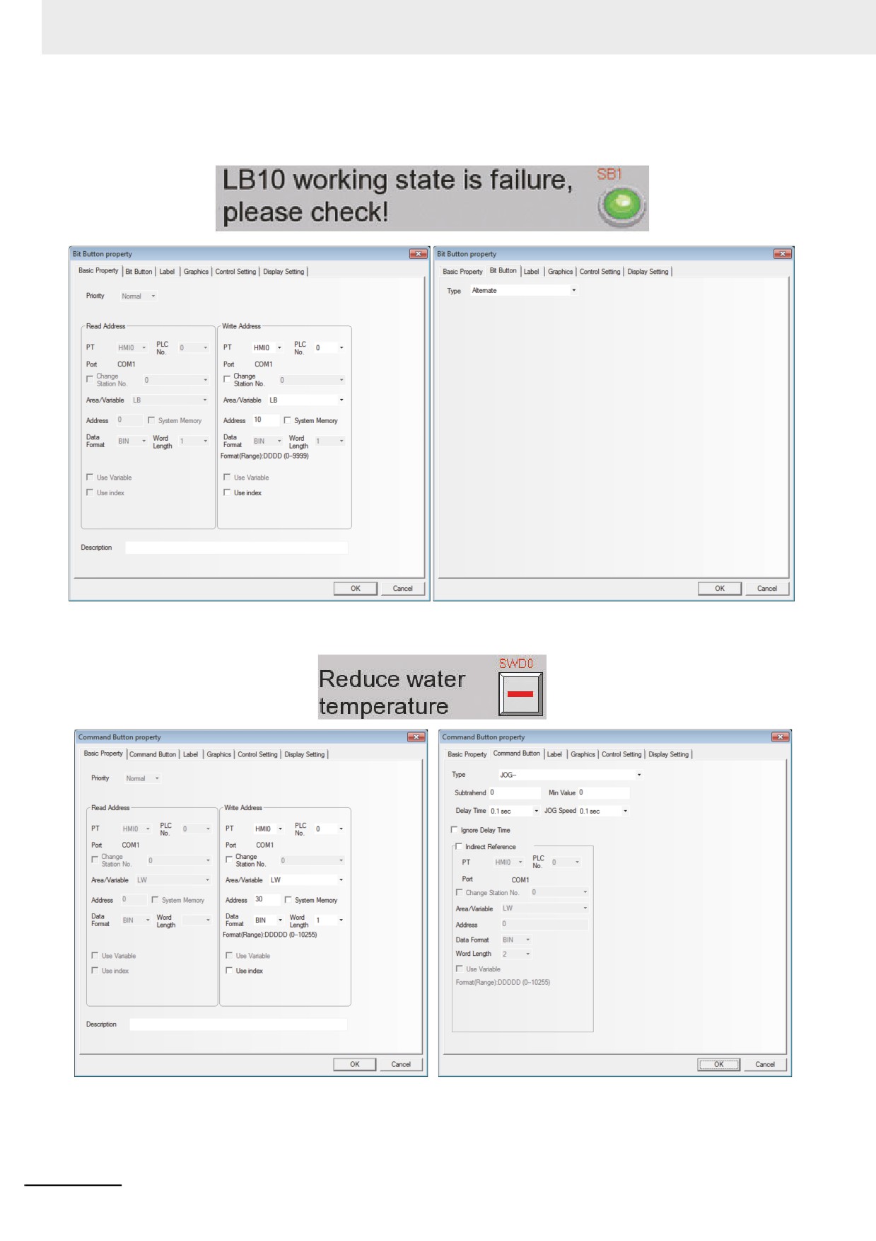
Create screen 4 with one Text component and one Bit Switch component controlling the LB10,
as shown below.
9
Create screen 5 with one Text component and one Command Button component, as shown below.
3-176
3 Functions of NB-Designer
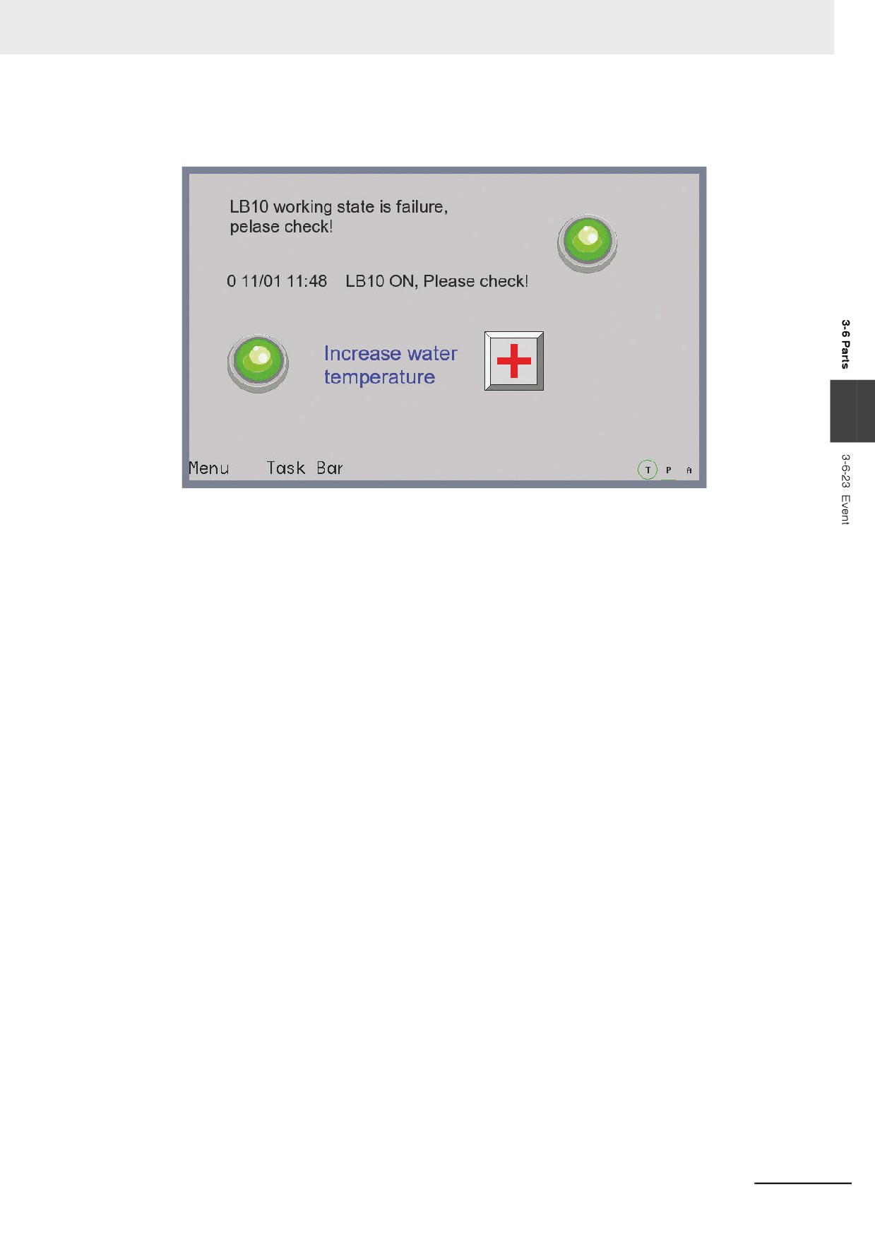
10 After [Save], [Compile], [Online/Offline test] or [Download] is selected, the operation effect of
the program is as shown below.
3
When LB10 or LW30 is triggered for its corresponding triggering conditions is satisfied, the
related event information will be displayed. The popup screen 4 and screen 5 for the 2 events
registered in the [Event Setting] are the pop-up screens to be ejected when the event is
triggered.
Note 1
For the pop-up screen, it will pop up only when the event is confirmed.
2
For the pop-up screen for the event triggering, it can be closed by the <Close screen> for the Function Key
or the triggering function <Write Data: No>.
3-177
3 Functions of NB-Designer
3-6-24
Note Book
Note Book component can modify or display the data in the specified word memory.
The value of the communications address is dealt as ASCII character. The input data is saved to a
consecutive memory with the “Read Address” as the first address. Low-byte character codes are
displayed on the left, while high-byte character codes are displayed on the right. It supports the display
of the multi-line text content and page turning, and can be used to make the operations such as Copy,
Cut and Paste etc. for the text contents in the selected area.
z Process of adding one Note Book component
1
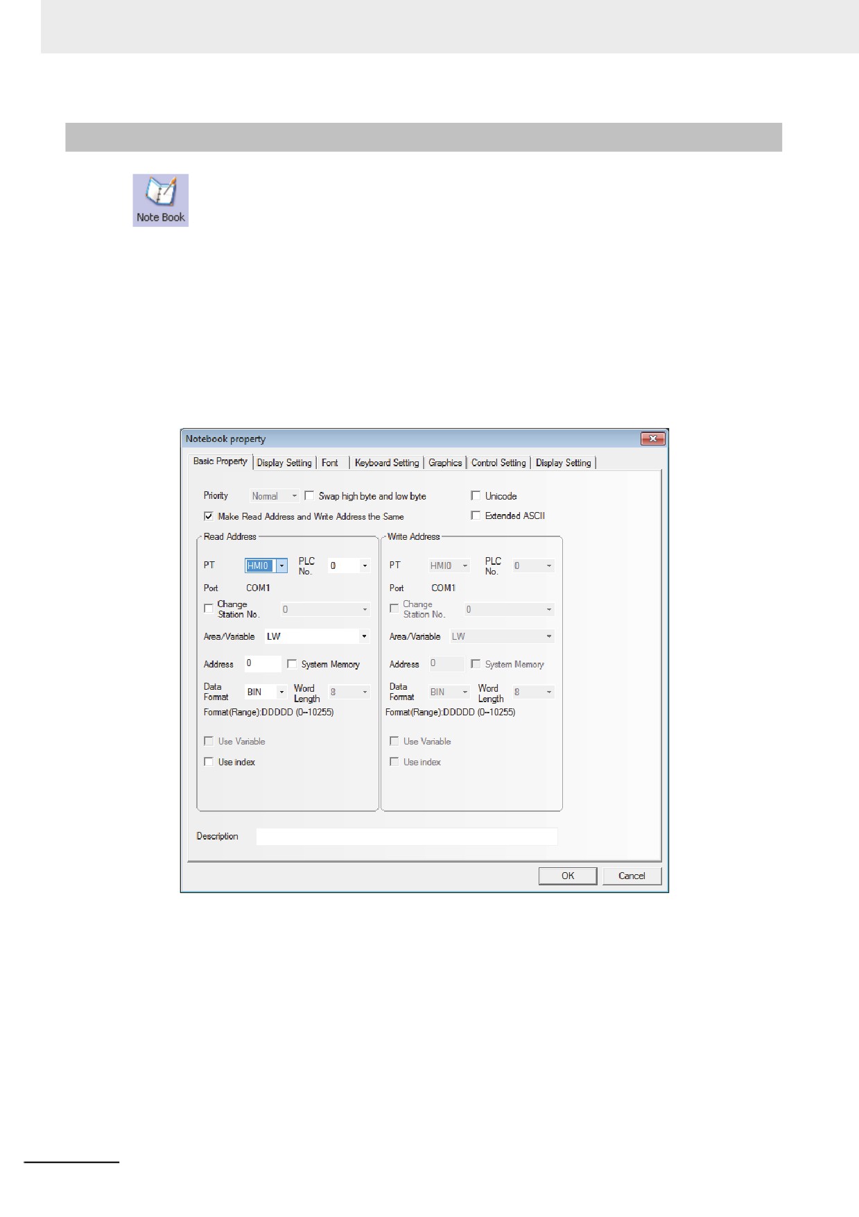
Press the Note Book component icon, drag it to the screen, then the [Basic Properties] dialog
box of the Note Book component will pop up.
3-178
3 Functions of NB-Designer
2
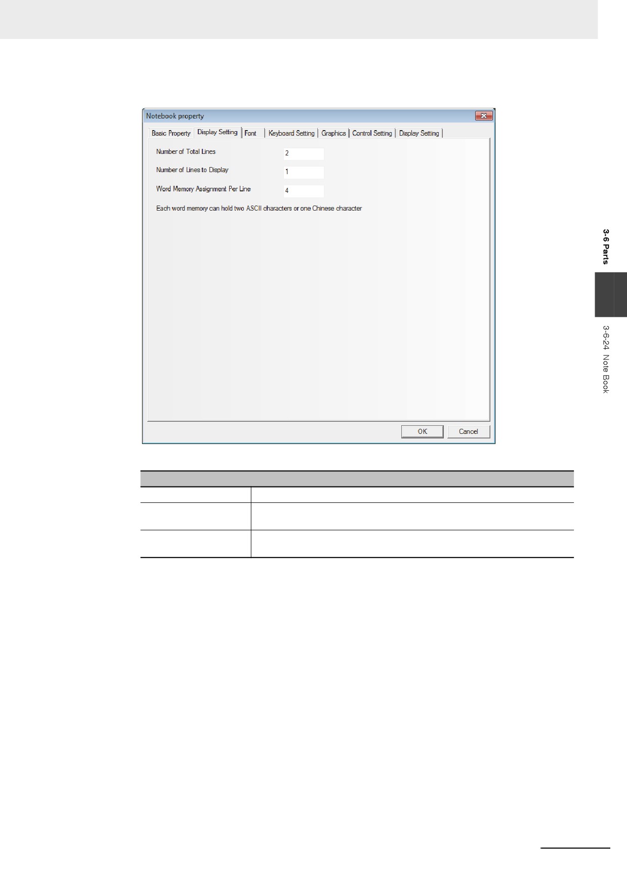
Switch to the [Display Setting] tab.
3
Descriptions of Note Book
Number of Total Lines
Refers to the total lines of the text that can be input.
Number of Display
Refers to the lines in the display area.
Lines
Word Memory
Refers to the maximum data length displayed in each line with the unit of
Assignment Per Line
“word”. It is one byte for ASCII character and two bytes for one word.
3-179
3 Functions of NB-Designer
3
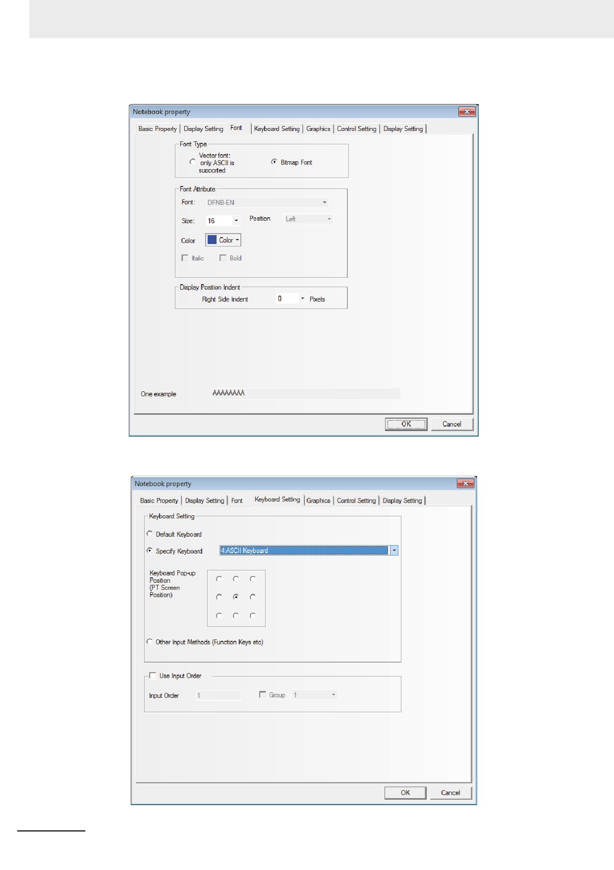
Switch to the [Font] tab.
4
Switch to the [Keyboard Setting] tab.
3-180
3 Functions of NB-Designer
5
Switch to the [Graphics] tab and select the Vector Graphics or bitmap representing the
touching area and touching state.
6
Switch to the [Control Setting] tab and make the Security Setting and set the Triggering action.
7
Press the [OK] button to complete the setup of the Note Book component.
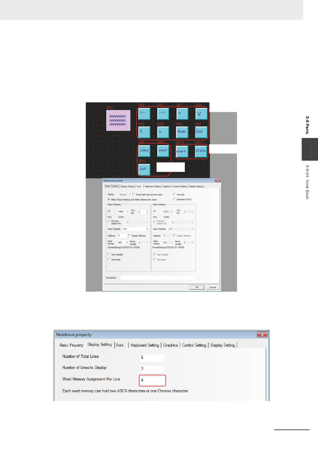
The editing of Note Book is as shown below:
Cursor
operating area
Selection
3
operating area
Extended
operating area
The specific Properties of the Note Book are set as shown below:
LW 9170 is used to realize page turning of the Note Book, and its value represents the start
line of the input area. The user can change this value to realize the display of the Note Book in
the page-turning way.
3-181
3 Functions of NB-Designer
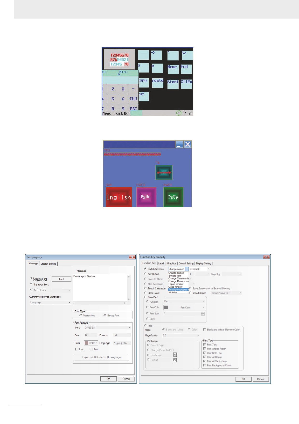
The offline test effect of the Note Book is as shown below:
z Example of using Text Input component to realize PinYin Input
The edited effect is as shown below:
PinYin Input Window
Please input your name:
The specific operation is as follows:
1
Make “PinYin Input Window” as the screen title, and place one Text component, as shown
below.
2
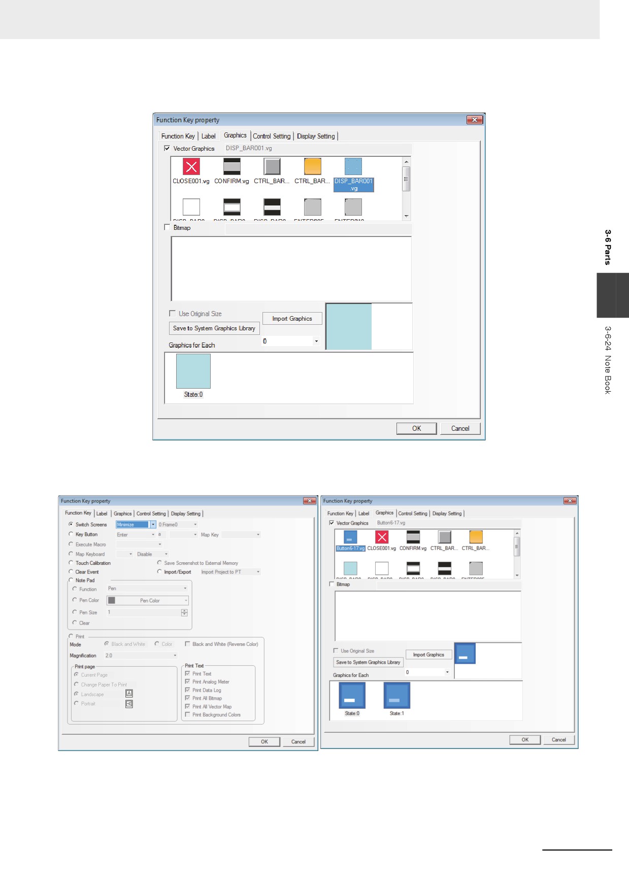
Place another function key with the Property “Switch Screen” of “pop-up screen title bar”, which
overlaps above the Text component (i.e. PinYin Input Window).
3-182
3 Functions of NB-Designer
Check “Vector Graphics” in the “Graphics” tab and select one Vector Graphics, as shown
below.
3
3
Place one function key with the Property of “Switch Screen” of “Minimize” in the “Function Key”
tab. Check “Vector Graphics” in the “Graphics” tab and select one Vector, as shown below.
3-183
3 Functions of NB-Designer
4
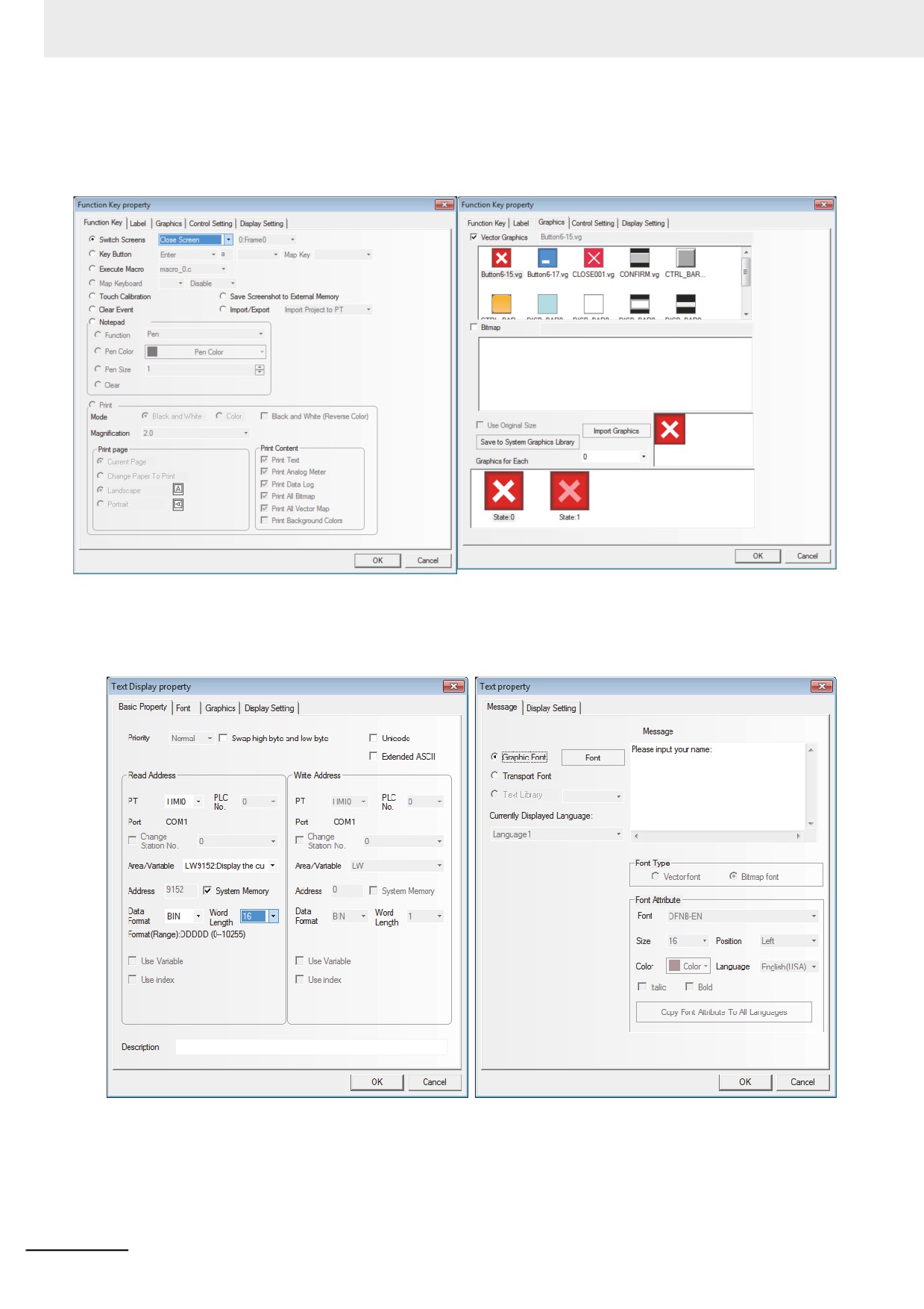
Place one function key with the Property of “Switch Screen” of “Close Screen” in the “Function
Key” tab. Check “Vector Graphics” in the “Graphics” tab and select one Vector, as shown
below.
5
Place one Text Display component LW9152 with the “Word Length” of “16”.
6
Place one static Text Display component with the contents of “Please input your name:”.
3-184
3 Functions of NB-Designer
7
Place another Text Input component LW20 with the “Word Length” of “4”.
8
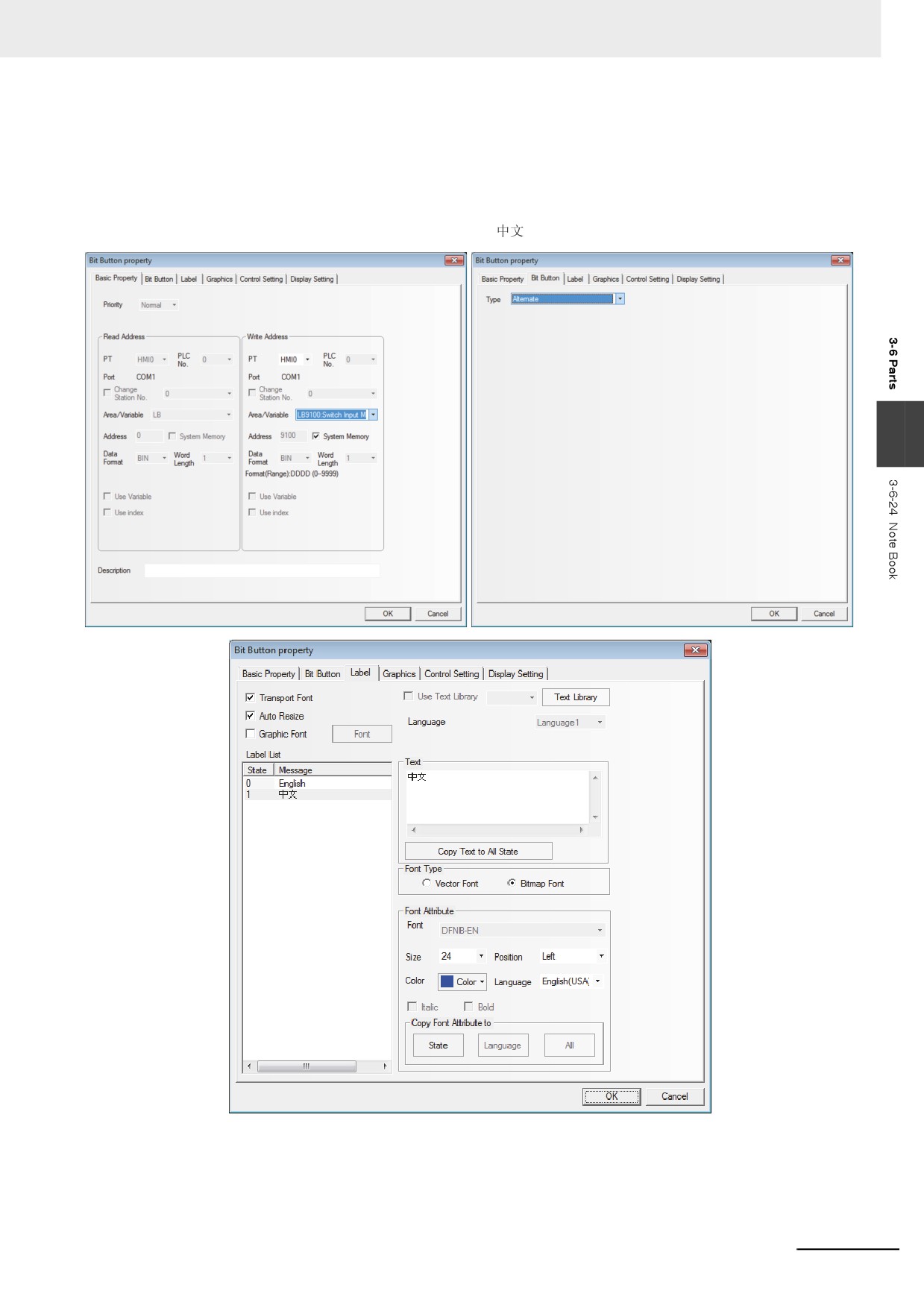
Create one Bit Button component with the “Write Address” of LB9100 in the “Basic Properties”
tab, “Type” in the “Bit Button” tab of “Alternate”, “Transport Font” being checked together with
the State 0 and State 1 of “English” and “
” respectively.
3
3-185
3 Functions of NB-Designer
9
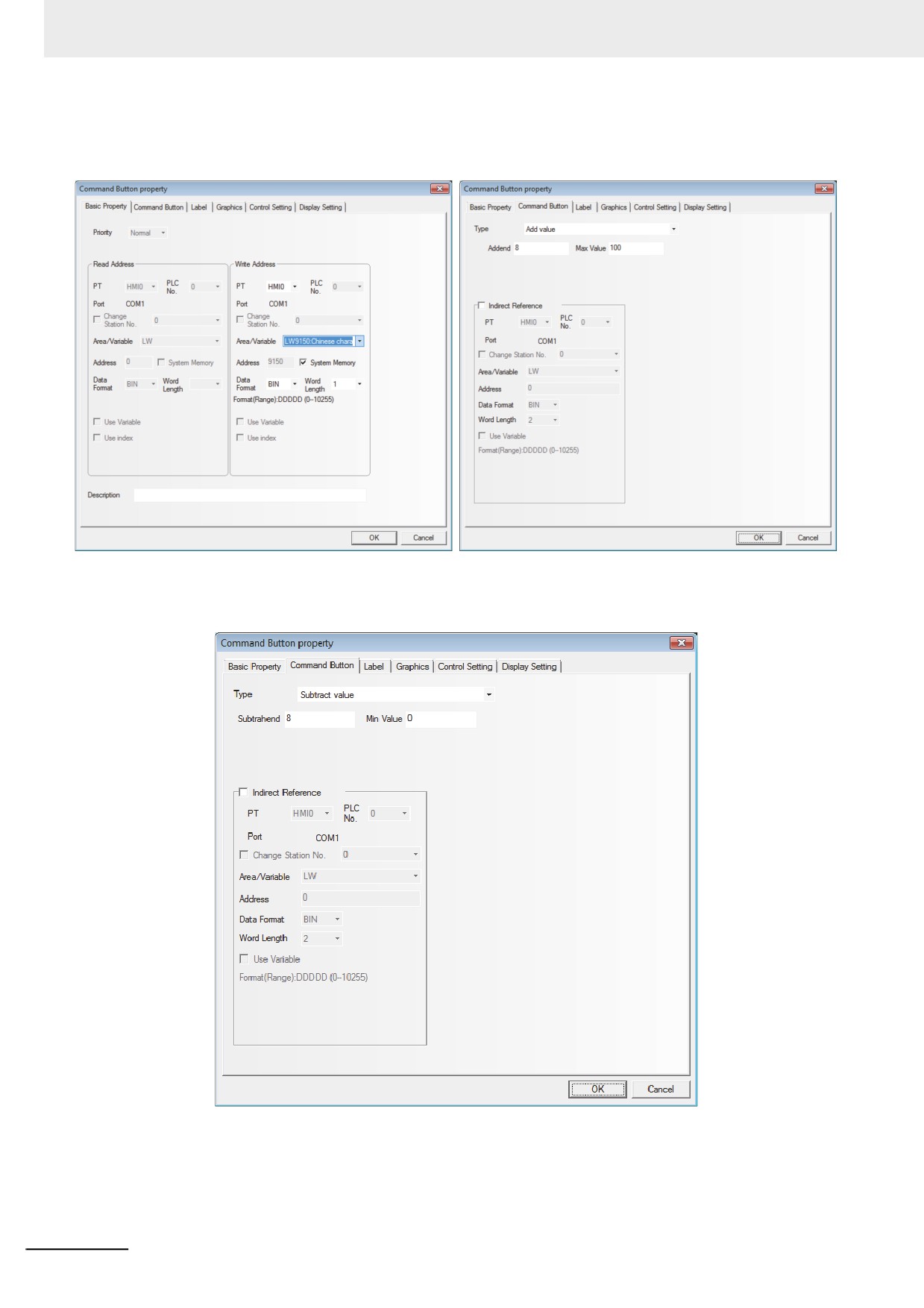
Place one Command Button component LW9150 with “Type”, “Addend” and “Max Value” of
“Add value”, “8” and “100” respectively in Command Button tab and the Label of “PgDn”.
10 Place one Command Button component LW9150 with “Type”, “Subtrahend” and “Min Value” of
“Subtract value”, “8” and “0” respectively in Command Button tab and the Label of “PgUp”.
3-186

3 Functions of NB-Designer
After all the components are placed well, the operation are as follows:
1
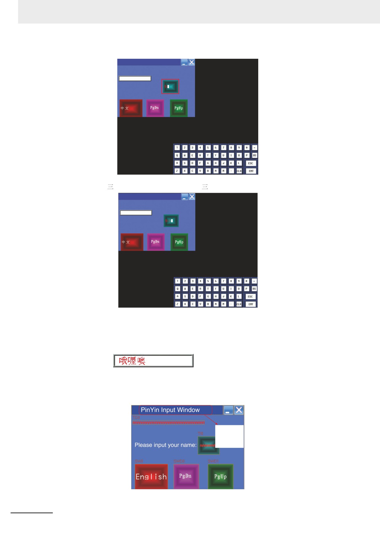
Trigger the Text Input component to make the cursor appear, as shown below.
PinYin Input Window
Please input your name:
2
Click the English-Chinese Switch once, then the input bar for Chinese input will appear, as
3
shown below.
PinYin Input Window
Please input your name:
3
Several homophones will appear in the Chinese input bar after the PinYin character is input,
and you can use the “PgUp” or “PgDn” button to realize page turning, and trigger the related
Chinese character to complete one Chinese character input process. As shown below, for
example, if “
” needs to be input, you just need to enter “zhang” through the character
keyboard.
PinYin Input Window
Please input your name:
Later, when
“
” is triggered, “
” will be displayed in the Text Input
component, as shown below.
3-187
3 Functions of NB-Designer
PinYin Input Window
Please input your name:
Trigger “
” after PinYin “san” is input, “
” will be displayed in the Text Input component.
PinYin Input Window
Please input your name:
Press “ENT” button in character keyboard to complete this input.
Addition1
If the character needs to be changed during the input process, the function keys of “BACK” or
“Clear” in the keyboard can be used to realize this operation.
2
, triggering the blank area of the Chinese Character Display
screen can realize the movement of this screen, which is similar to the screen console of the
function key.
4
Clicking the “PinYin Input Window” bar can realize the screen movement, as shown below.
Press the
blue title bar
can be move
the screen
3-188
3 Functions of NB-Designer
5
Clicking the “Minimize (i.e. “-”) icon” can make the screen minimized to the task bar. And
clicking the task bar again will make the screen return to the state before it is minimized.
6
Clicking the “Close (i.e. “X”)” icon to close the screen.
The PinYin Input for the Note Book is similar to that for the Text component, and many
Properties of the Note Book component are realized through the function keys.
3-6-25
Word Neon Lamp
The text string which is specified as Label is displayed in loopy-moving way, and it supports
the label contents corresponding to 256 (max.) states in the loopy-moving way.
3
z Process of adding one Word Neon Lamp component
1
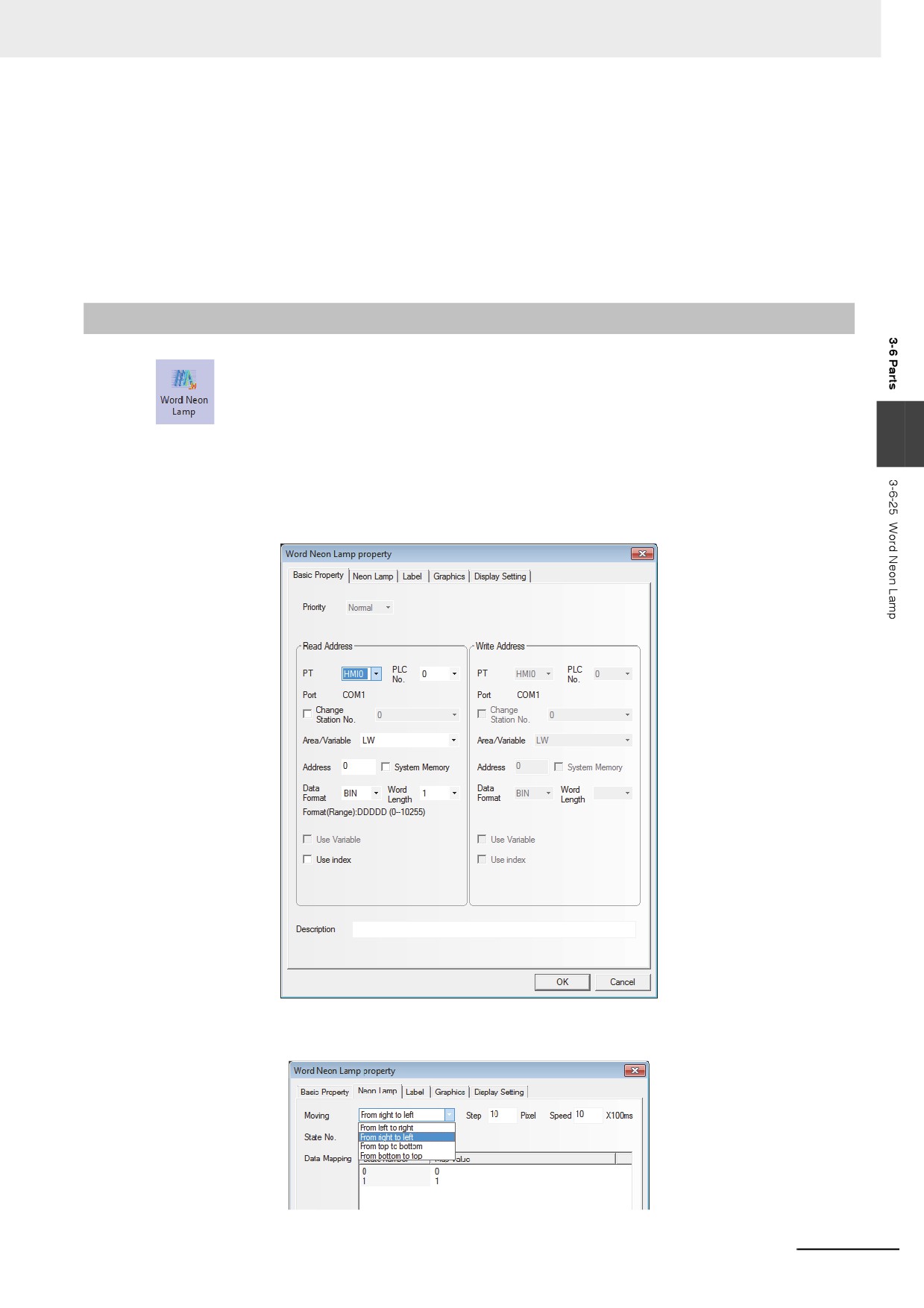
Press the Word Neon Lamp component icon, drag it to the screen, then the [Basic Properties]
of Word Neon Lamp component will pop up.
2
Switch to the [Neon Lamp] tab and make settings of “Moving Type”, “State No.”, “Step” and
“Speed” respectively.
3-189
3 Functions of NB-Designer
3
Switch to the [Label] tab and add the text corresponding to the state.
4
Switch to the [Graphics] tab and select the Vector Graphics or bitmap representing the
touching area and touching state.
5
Press the [OK] button to complete the setup of the Word Neon Lamp component.
3-6-26
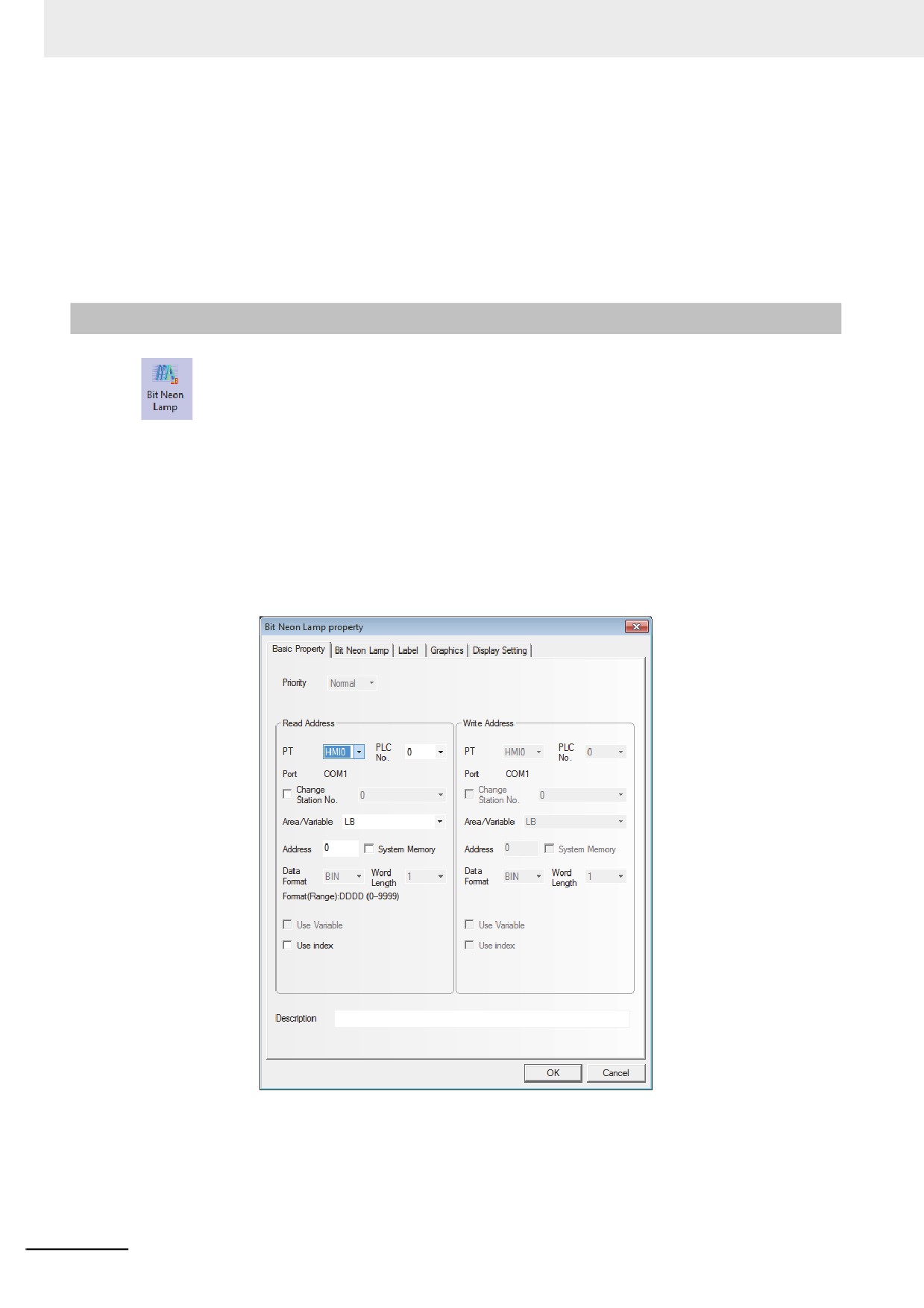
Bit Neon Lamp
The text string which is specified as Label displayed in loopy-moving way, and it supports the
label contents corresponding to State 0 and State 1 in the loopy-moving way.
The difference of the Word Neon Lamp and the Bit Neon Lamp is the controlling method, and the
former selects the different states ranging from 1 to 256 by changing the memory value, while the latter
changes the display state (only 2 states available) by changing the state of the control bit.
z Process of adding one Bit Neon Lamp component
1
Press the Bit Neon Lamp component icon, drag it to the screen, then the [Basic Properties] of
Bit Neon Lamp component will pop up.
3-190
3 Functions of NB-Designer
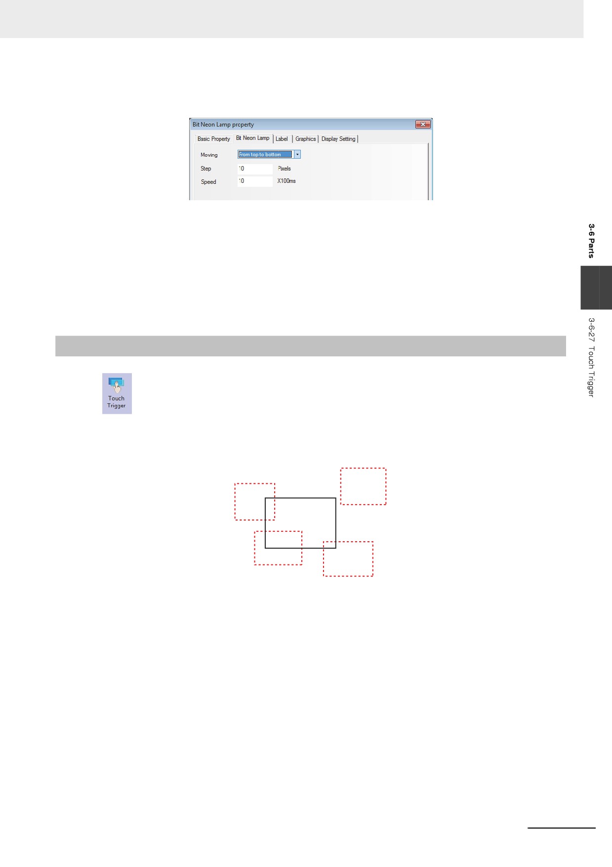
2
Switch to the [Bit Neon Lamp] tab and make settings of “Moving Type”, “Step” and “Speed”
respectively.
3
Switch to the [Label] tab and add the text corresponding to the state.
4
Switch to the [Graphics] tab and select the Vector Graphics or bitmap representing the
touching area and touching state.
3
5
Press the [OK] button to complete the setup of the Bit Neon Lamp component.
3-6-27
Touch Trigger
The Touch Trigger component is applicable to the conditions where the several components
can be triggered to act not through the triggering method. When the triggering conditions for the
specified memory of the Touch Trigger component are satisfied, the components placed in the valid
area for the Touch Trigger component can be triggered to act.
2)
3)
Touch Trigger
component
4)
1)
1), 3) and 4) locate in the valid triggering area, while 2) locates in the invalid triggering area.
Therefore, when the set triggering conditions for the specified memory of the Touch Trigger component
are satisfied, the components in area 1), 3) and 4) will be triggered, while that in area 2) will not be
triggered.
3-191
3 Functions of NB-Designer
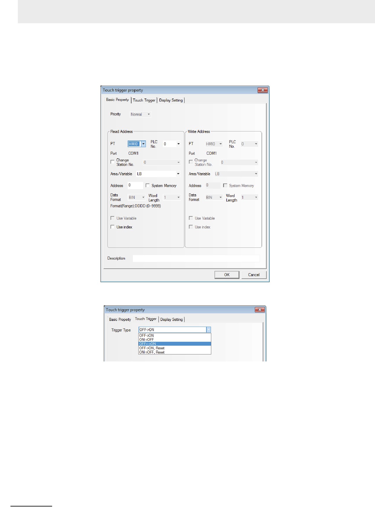
z Process of adding one Touch Trigger component
1
Press the Touch Trigger component icon, drag it to the screen, then the [Basic Properties]
dialog box of Touch Trigger component will pop up.
2
Switch to the [Touch Trigger] tab and select the Trigger Type.
3
Press the [OK] button to complete the setup of the Touch Trigger component.
3-192
3 Functions of NB-Designer
3-6-28
Table
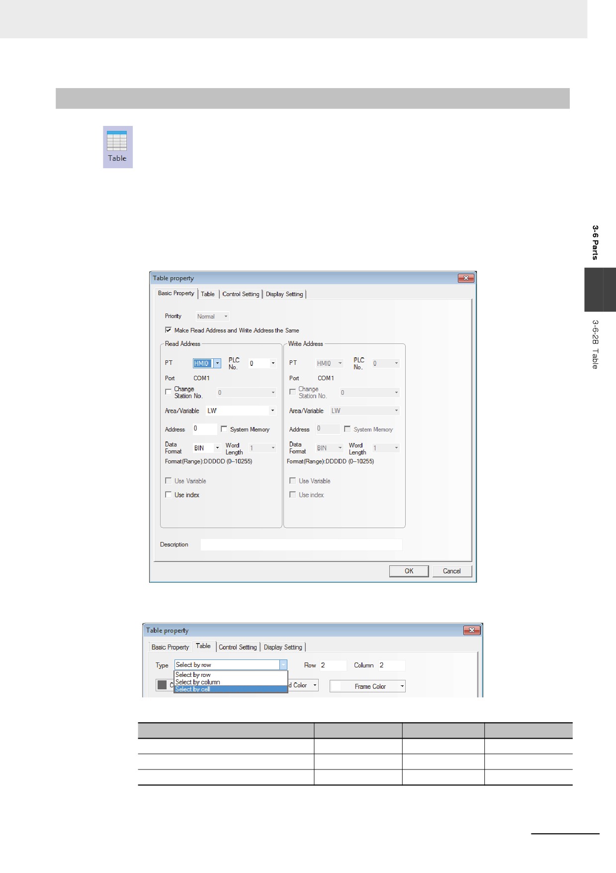
The Table component can make the selection type of “Select by row”, “Select by Column” and
“Select by cell”. The user can set the “Row”, “Column”, “Color when Selected”, “Background Color”,
“Border Color”, and write the selected Row No. and Column No. into the specified memory.
z Process of adding one Table component
1
Press the Table component icon, drag it to the screen, then the [Basic Properties] dialog box of
the Table component will pop up.
3
2
Switch to the [Table] tab and make the settings of “Row”, “Column” and “Type”.
The related Properties are as follows:
Type
Select by row
Select by col
Select by cell
memory corresponding to Row
First address
-
First address
memory corresponding to Column
-
First address
First address + 1
Number of Occupied memories
1
1
2
3-193
3 Functions of NB-Designer
3
Switch to the [Control Setting] tab and make the Security Setting and set the Triggering action.
4
Press the [OK] button to complete the setup of the Table component.
The test effect of the Table component is as shown below.
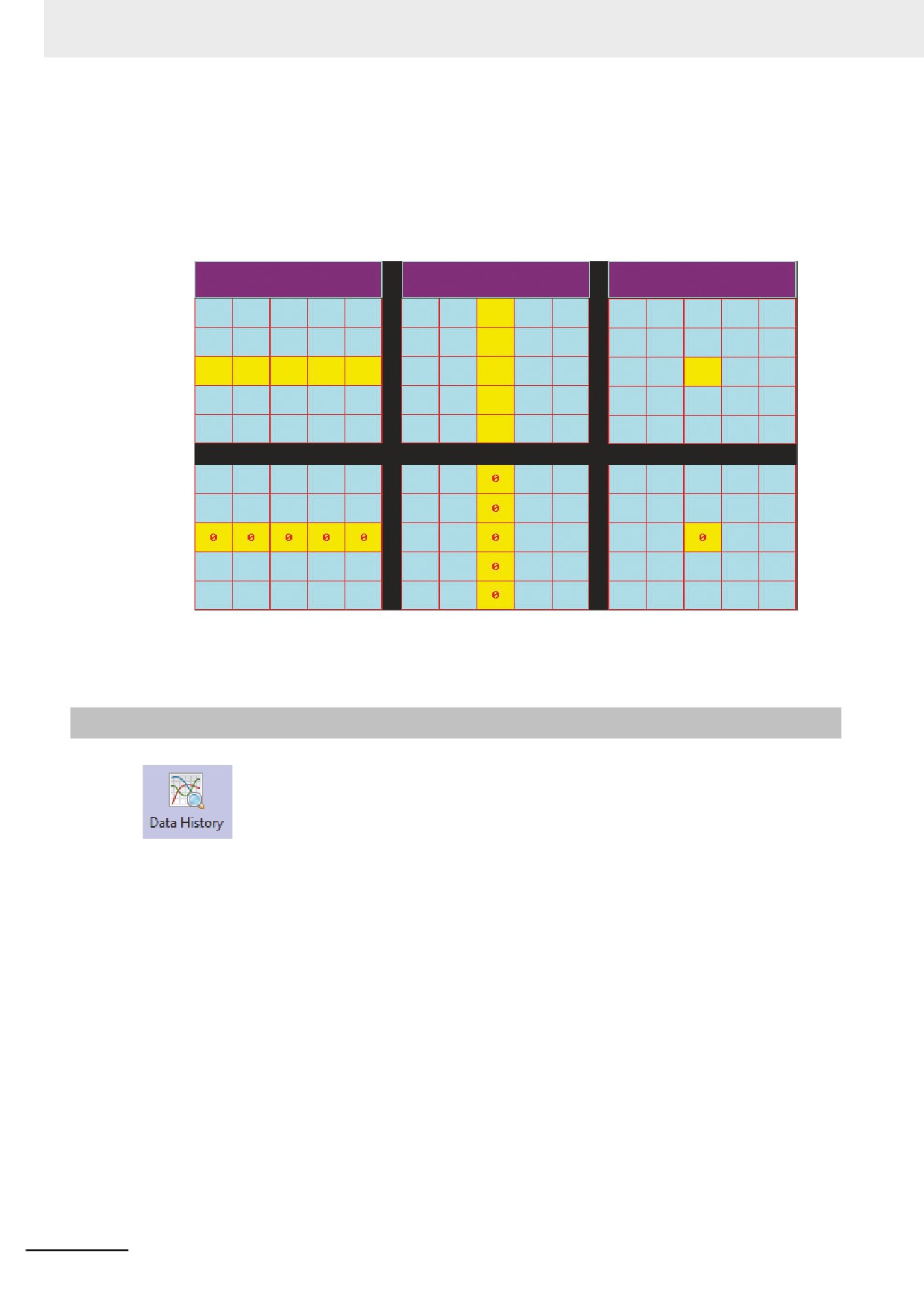
Select by row 2
Select by col 2
Select by cell 2
Grid component application
If required, the Table component can also be used in combination with the Number Input component
and the Macro, thus controlling the display condition through the Macro.
3-6-29
Data History
The Data History component can be used to read a series of date in consecutive memories
from the specified word memory(s) inside PT, PLC or word memory(s) of the controller periodically and
display them in the table form.
Note 1
The sampled data must be consecutive. When the “Save to Recipe Data Field” is checked in the [Save
Data History] tab, only the saving of a little amount of data is possible for the limited capacity of recipe data
field.
2
The [Read Address] for the Data History component is the memory address for data sampling by the 1st
channel.
3
The Word Length of memory for Data History component is determined by the channel number, i.e. if
channel number is m (0<m<17), the World Length will be m.
4
Using the Data History component, the user must be check one or both of “Save to Recipe Data Field” and
“Save to External Device” options in the [Save Data History] tab in the [Data History Component Property]
dialog box.
3-194
3 Functions of NB-Designer
z Process of adding one Data History component
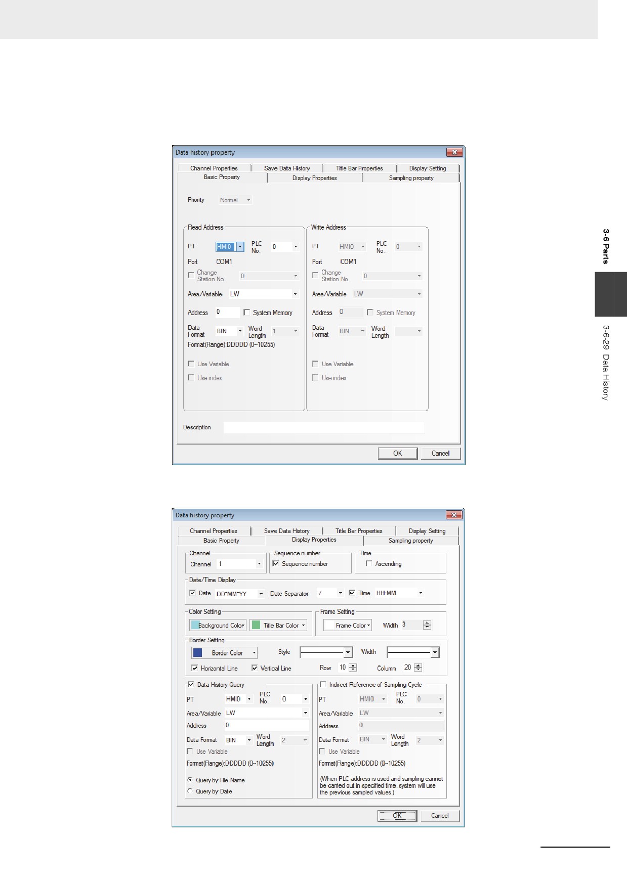
1
Press the Data History component icon, drag it to the screen, then the [Basic Properties] dialog
box of the Data History component will pop up.
3
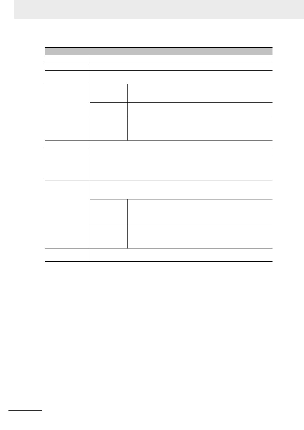
2
Switch to the [Display Properties] tab and make the settings of display format and color etc.
3-195
3 Functions of NB-Designer
Descriptions of Display Properties
Channel
Refers to the channel number of the memory to be sampled, and the channel is up to 16.
Sequence number
Determines whether to display the No. of the sampling data information.
Ascending
When this option is checked, the sampling data information will be displayed in the
ascending order, i.e. the latest sampling data will be displayed on the bottom.
Date/Time Display
Date
Checking in the checkbox allows the sampling date displayed in the
selected date format. The 3 formats are available, and YY, MM and
DD refer to the year, month and date respectively.
Date Separator
Selects the data separator with 3 formats available. For example:
11/06/24.
Time
Checking it means the sampling time will be displayed and the time
format can be selected. There are 3 formats available, and HH, MM,
SS and MS refer to the hour, minute, second and millisecond
respectively.
Color Setting
Sets the Background Color and Title Bar Color for the table respectively.
Frame Setting
Sets the Frame Color and Width for the table.
Border Setting
Set the color, types, and width of Border, row spacing, and column spacing with the unit
of “pixel point”. Checking the “Horizontal Line” check box means the border will be
displayed horizontally, and checking “Vertical Line” means the border will be displayed
vertically.
Data History Query
The historical sampled data stored in the external memory can be searched by address
of the word memory specified in “Data History Query” setting. The Word Length of the
specified memory address is 2 by default.
Query by File
With the “Query by File Name” being checked, it means to call out the
Name
data history sampled today or in the latest day when the value of
specified memory is 0, while the data history sampled in the last time
when the value of specified memory is 1, and so on.
Query by Date
When “Query by Date” is checked, the date will be input into the
specified memory and the data history corresponding to the date will
be called out. The date format is yyyymmdd, where yyyy, mm and dd
refer to year, month and date respectively.
Indirect Reference
When Indirect Reference is used, the sampling time will be read from the specified
of Sampling Cycle
memory.
Note When the variable is specified in the sampling cycle, if the value cannot be obtained within the regulated
time, the value which was obtained previously will be used.
3-196
3 Functions of NB-Designer
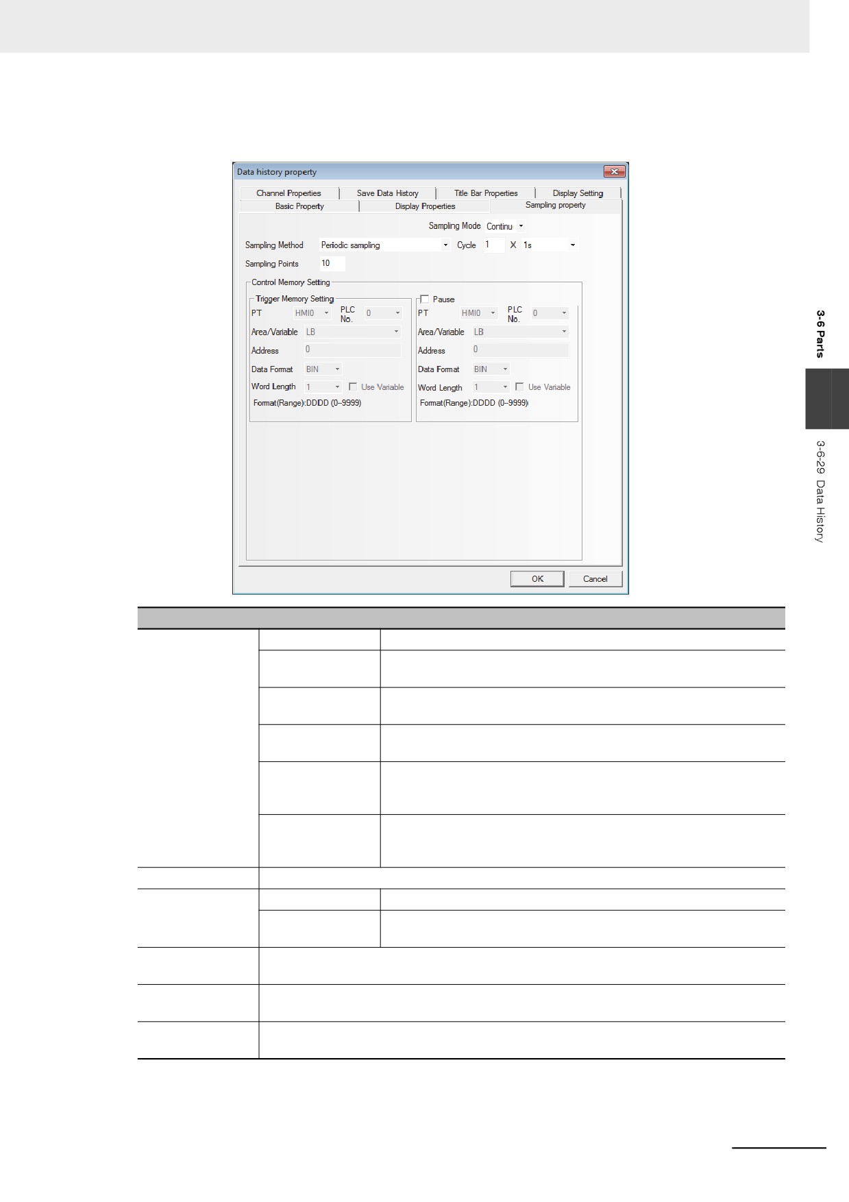
3
Switch to the [Sampling Property] tab and make the settings of “Sampling Method”, “Cycle”,
“Sampling Points” and “Pause-Clear” and etc.
3
Descriptions of Background Property
Sampling Method
Periodic sampling
The data is sampled timely.
OFF˘ ON trigger
Only when the state of the specified bit address turns ON from OFF,
sampling
the sampling is triggered.
ON˘ OFF trigger
Only when the state of the specified bit address turns OFF from ON,
sampling
the sampling is triggered.
OFF¯˘ ON trigger
Only when the state of the specified bit address changes, the
sampling
sampling is triggered.
OFF˘ ON reset
Only the state of the specified bit address turns ON from OFF, the
trigger sampling
sampling is triggered, and the state of the specified bit address will be
reset automatically after the triggering.
ON˘ OFF reset
Only the state of the specified bit address turns OFF from ON, the
trigger sampling
sampling is triggered, and the state of the specified bit address will be
reset automatically after the triggering.
Cycle
Refers to the interval between 2 sampling points with the unit of “s”or “100 ms”.
Sampling Mode
Continue
When all the sampling points end, the sampling still continues.
Once
When all the sampling points end, the sampling will stop, which
means sampling is only performed once.
Sampling Points
When the sampling method is “Once”, the sampling will stop after the set “Sampling Points”
is finished.
Trigger memory
When the Trigger memory Setting is used for the sampling method, the memory address to
Setting
be read will be specified.
Pause- Clear
The default Word Length is 2. “Pause” function can stop the data sampling operation
temporarily. In addition, the “Clear” function here is invalid for the Data History component.
Note When the trigger sampling is used, if multiple samplings are executed at the same timing, only single value
might be acquired.
When such a state is assumed, place the Data Transmission component and others on the Common Sheet
and acquire the necessary data at local memory to perform the sampling for the local memory.
3-197
3 Functions of NB-Designer
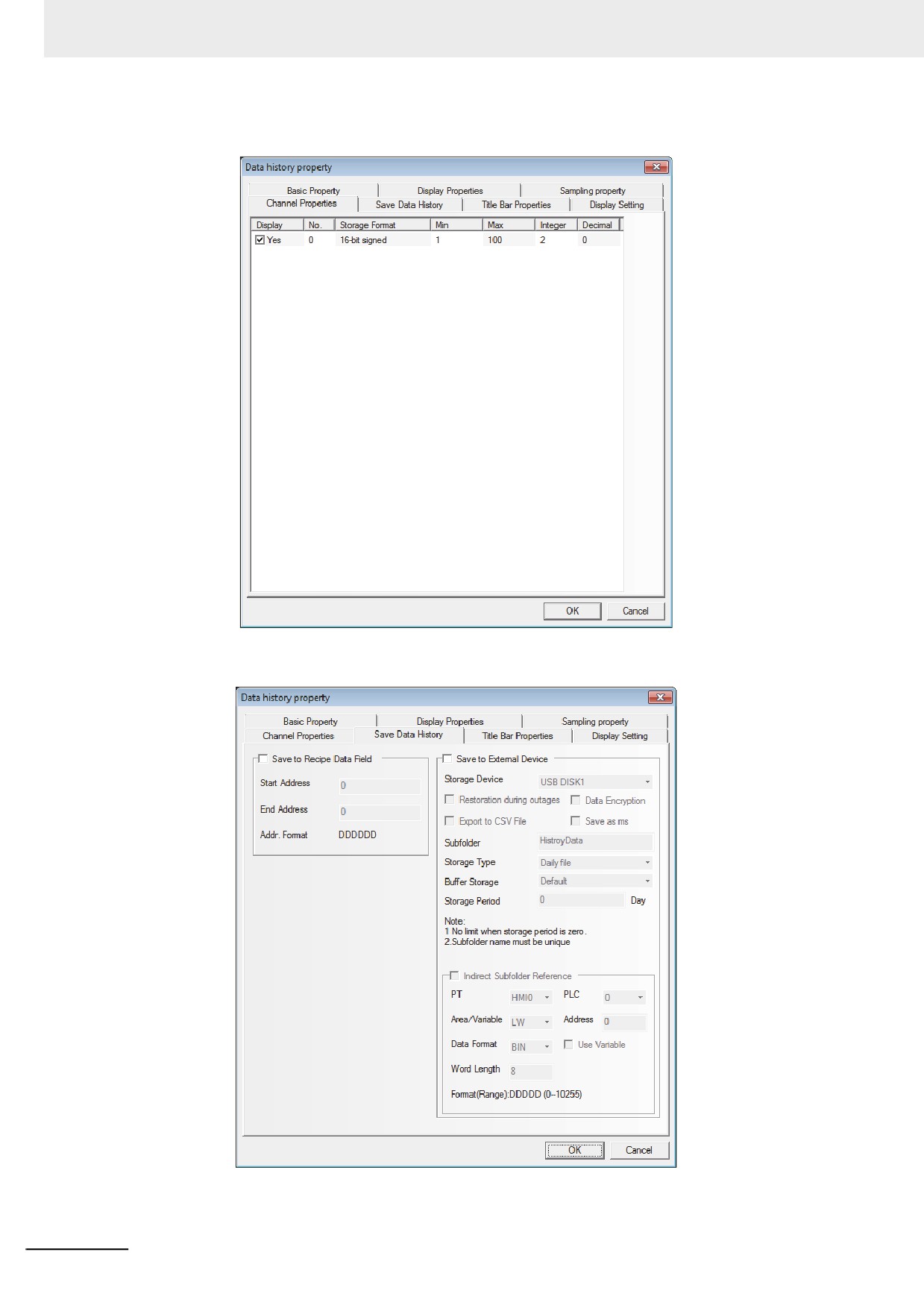
4
Switch to the [Channel Properties] tab and set the display information for each channel.
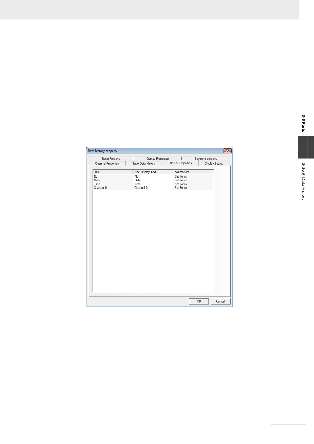
5
Switch to the [Save Data History] tab and set the “Start Address.” etc. to be saved.
3-198
3 Functions of NB-Designer
• When the Data History component and the Data Log component are used in combination and
their addresses are the same, it just needs to set “Save to Recipe Data Field” for either of
them.
• If the Data History component is needed to display the value of the Data Log, the value in PLC
can be transmitted to the LW of the local memory by the Timer or the Data Transmission com-
ponent.
• If the user needs to save the data for a long period and has low requirement of the interval for
the data saving, it is recommended the sampling time will be as long as possible.
• The memory area of the Data History includes "information area" for 40 bytes or 20 words.
Additionally, the memory area includes the "time area" indicating sampled points x 4 words per
page and the "data area" indicating sampled points x word length per page.
• When the storage period is set, the file deletion is performed at the first sampling after the star-
tup and every 24 hours. At the timing, any files which is beyond the storage period are deleted.
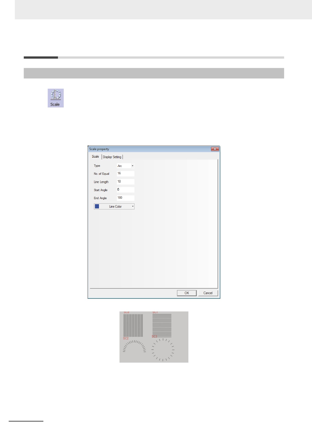
6
Switch to the [Title Bar Properties] tab and make settings of “Title” and “column font” etc.
3
7
Press the [OK] button to complete the setup of the Data History component.
3-199
3 Functions of NB-Designer
3-7
Function Parts
3-7-1
Scale
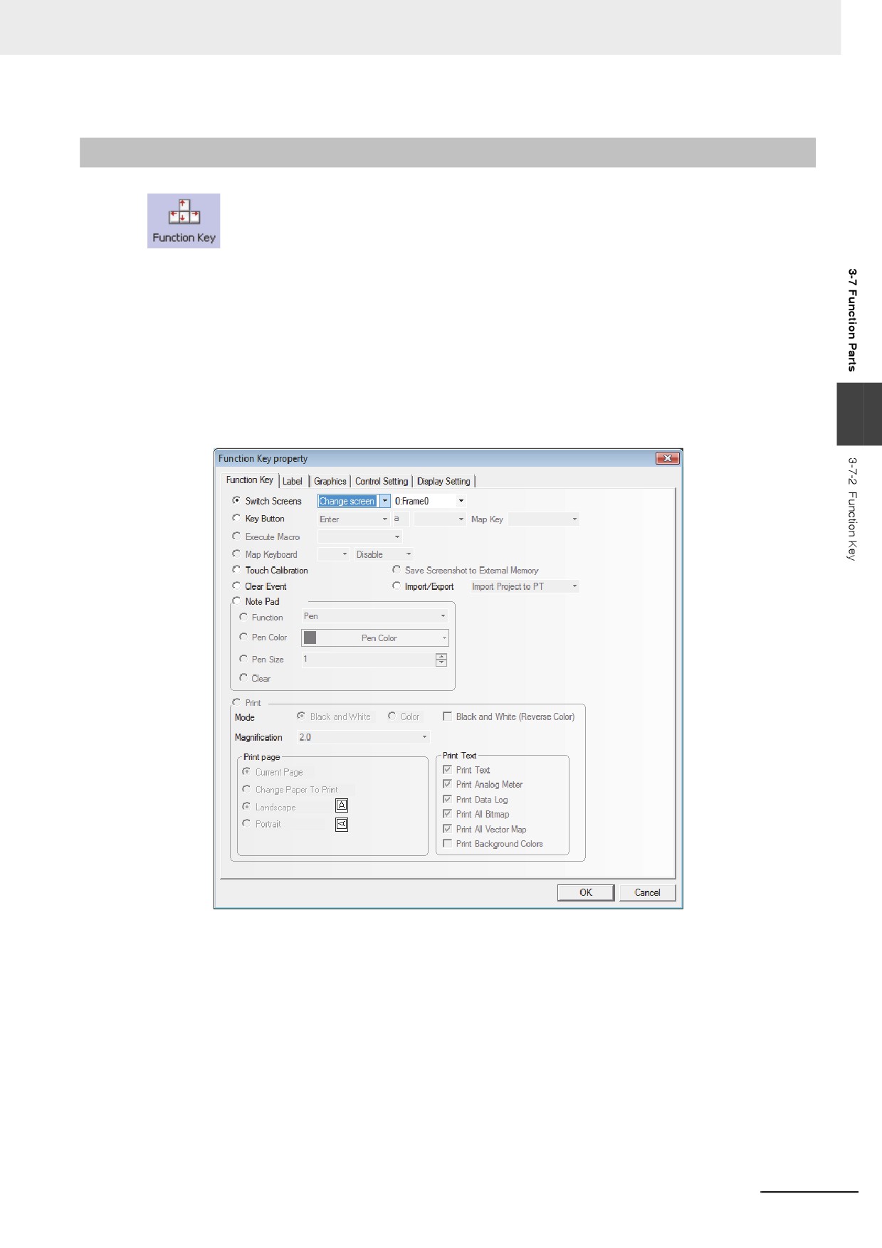
It is applicable to the conditions with the requirement of equal-division notation.
z Process of adding one Scale component
1
Press the Scale component icon, drag it to the screen, then the [Scale Property] dialog box will
pop up.
Type: Includes Vertical, Horizontal, Arc and Circularity.
No. of Equal: Set the number of equal-division for the graphics between 2 and 255.
Line Length: Set the length of the scale between 1 and 24.
Start Angle/End Angle: The start angle and the end angle of the arc between 0 and 360
degree.
2
Press the [OK] button to complete the setup.
3-200
3 Functions of NB-Designer
3-7-2
Function Key
Function Key provides functions such as “Switch Screens”, “Keyboard Function”, “Execute
Macro”, “Touch Calibration”, “Clear Event” and “Message Board” etc. The function key is not controlled
by the memory address, so the execution of specified function needs to be activated by touching this
component.
z Process of adding one Function Key
1
Drag the Function Key icon after it is pressed and display “Function Key Property”. In “Function
Key” tab, allocate functions such as “Switch Screens”, “Key Button”, “Execute Macro”, “Touch
Calibration”, “Clear Event”, “Notepad” for each function key. The NB-Series does not support
3
“Print” currently.
2
Go to the [Label] tab and fill in the text to be displayed.
3
Go to the [Graphics] tab and select the Vector Graphics or Bitmap to display the state.
4
Go to the [Control Setting] tab and make the Security Setting and set the Triggering action.
5
Press the [OK] button to adjust the position and size of the Function Key.
3-201
3 Functions of NB-Designer
z Function Key
1
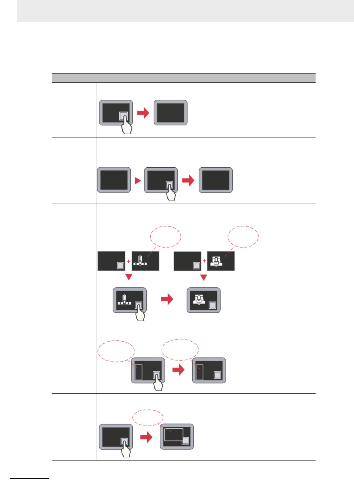
Switch Screen
Descriptions of Switch Screen
Change
Pressing the Function Key will make the current Base Screen including all of the pop-up
Screens
screens closed and the Base Screen with the specified Screen No. will be switched to.
Frame 0
Frame 10
Backward
Pressing the Function Key can make the current Base Screen closed and return to the
latest opened Base Screen, which is effective only for the Base Screen. For example, when
pressing the Function Key in “Frame 10” after “Frame 0” has switched to “Frame 10”,
“Frame 10” will be closed and the Screen will return to “Frame 0”.
Frame 0
Frame 10
Frame 0
Change
After the Function Key is pressed, the Common Sheet (Frame 1 is the system default
Common Sheet
screen.) can be replaced by the specified screen which will become the new Common
Sheet.
Common
Common
Sheet
Sheet
Frame 0
Frame 1
Frame 0
Frame 10
Frame 0
Frame 0
Change Menu
After the Function Key is pressed, the Menu Screen (Frame 2 is the system default screen.)
Screen
can be replaced by the specified screen which will become the new Menu Screen.
Frame2
Frame10
Fast Selection
Frame 0
Fast Selection
Frame 0
Pop-up Screen
After the Function Key is pressed, the specified screen will pop up and be displayed above
the current Base Screen, and the current screen will not be closed.
Pop-up
Frame 0
Screen
Frame 0
3-202