OMRON NB-Designer OPERATION MANUAL (NB-series, 2020) - page 7
3 Functions of NB-Designer
3-6-15
Analog Meter
Analog Meter can display the data in the specified memory by means of a Analog Meter
diagram.
z Process of adding one Analog Meter component
1
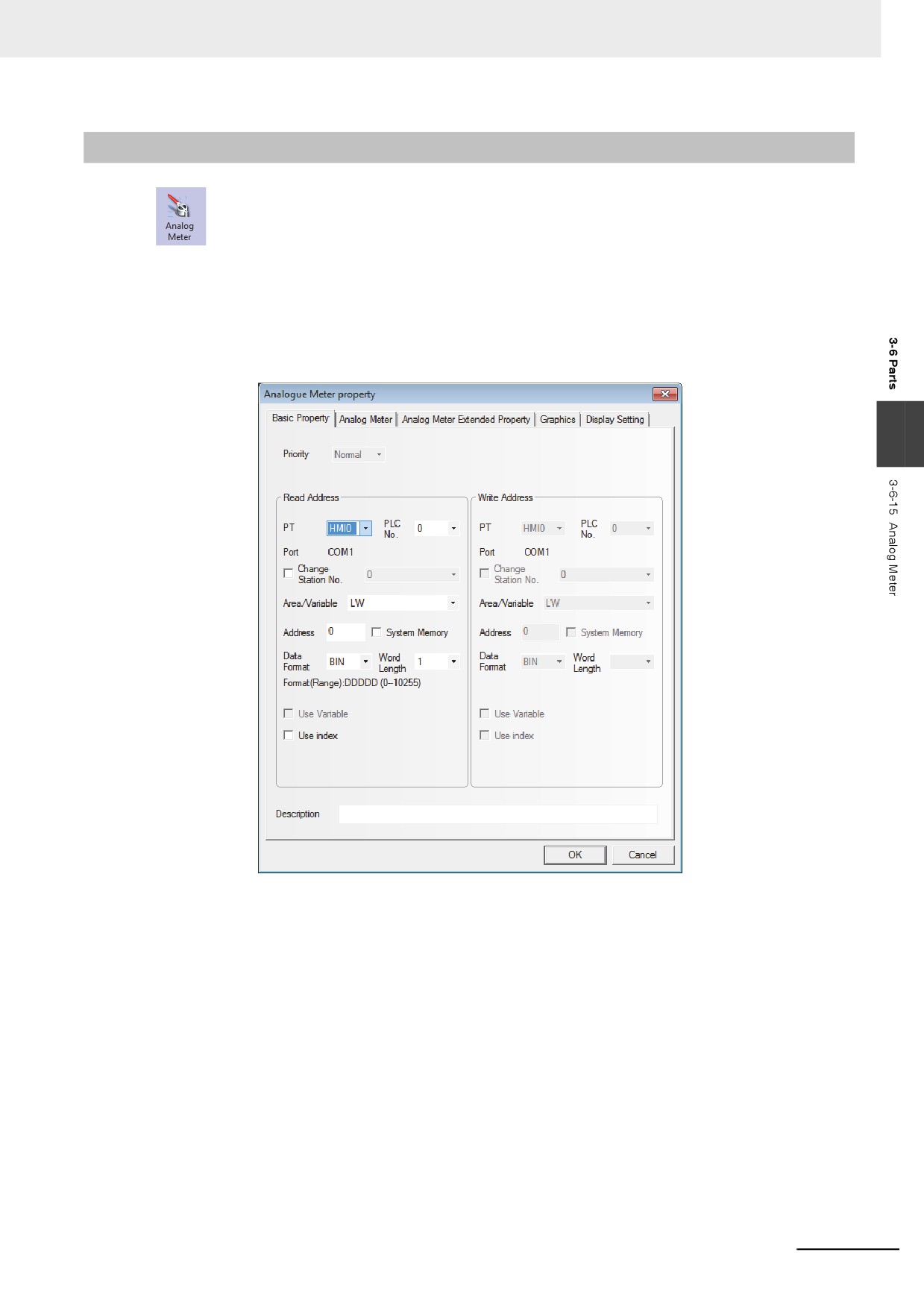
Press the Analog Meter component icon, drag it to the screen, then the [Basic Properties]
dialog box of the Analog Meter component will pop up.
3
Read Address: Refers to the word address of the value displayed by the component.
Address: Refers to the first address of the word address corresponding to the Analog Meter
component.
Word Length: 1 and 2 are available for the read address.
3-143
3 Functions of NB-Designer
2
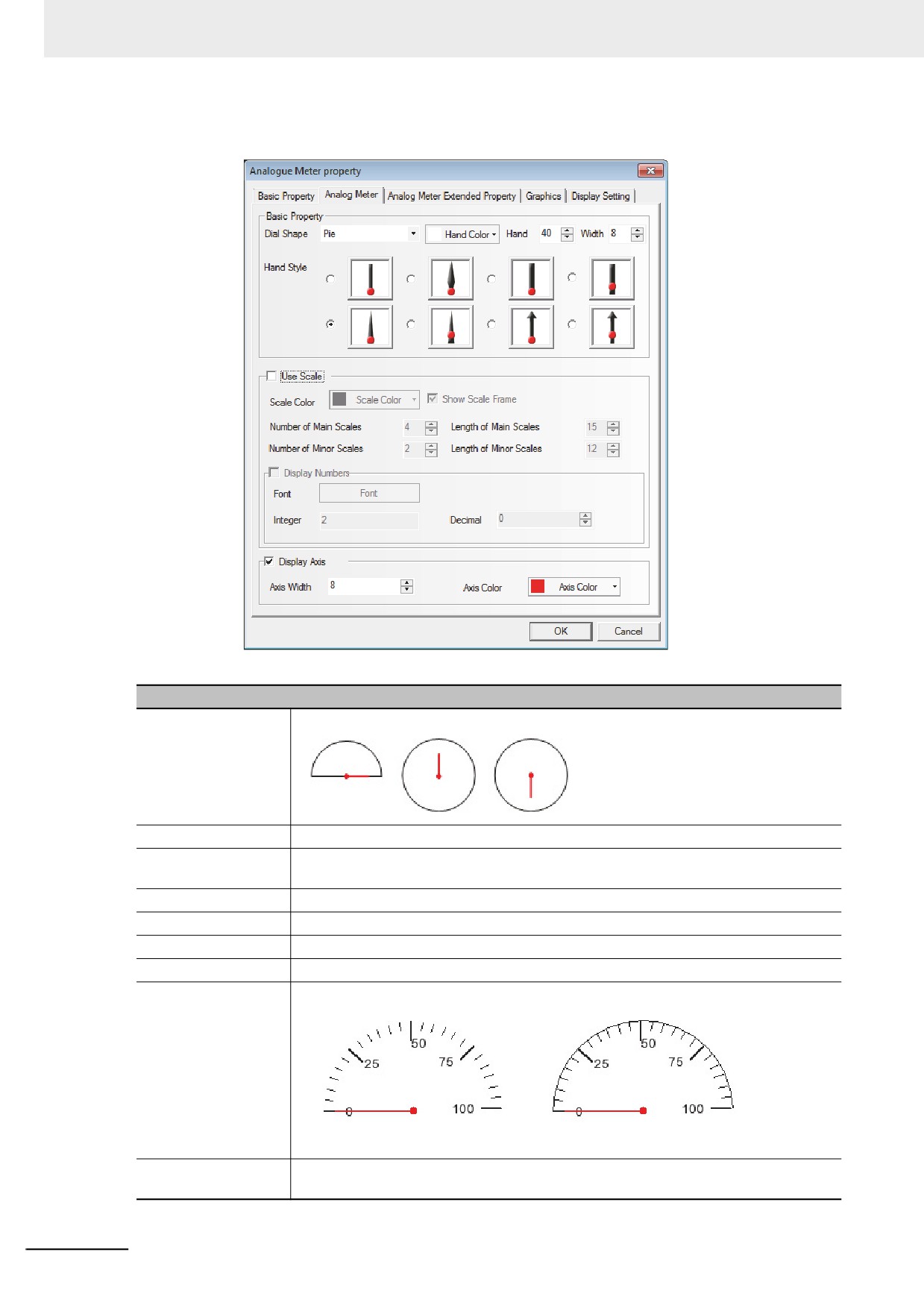
Switch to the [Analog Meter] tab.
Descriptions of Analog Meter Component Properties
Dial Shape
Includes Pie, Circularity (up pointer) and Circularity (down pointer).
Hand Color
Selects the color of the hand of the Analog Meter component.
Length
Sets the length of the hand of the Analog Meter component. The maximum length
cannot be longer than the radius of the meter.
Width
Sets the width of the hand of the Analog Meter component.
Hand Style
Sets the style of the hand of the Analog Meter component.
Use Scale
Check the check box to use the scale.
Scale Color
Selects the color of the display scale of the Analog Meter component.
Show Scale Frame
Checking it means the scale frame needs to be displayed.
No use show scale frame
Use show scale frame
Number of Main
Sets the number of the main scale of the Analog Meter component. (0 to 50 available)
Scales
3-144
3 Functions of NB-Designer
Descriptions of Analog Meter Component Properties
Length of Main Scales
Sets the length of the main scale of the Analog Meter component. The maximum length
cannot be longer than the radius of the meter.
Number of Minor Scale
Sets the number of the minor scale of the Analog Meter component. (0 to 10 available)
Length of Minor Scale
Sets the length of the minor scale of the Analog Meter component. The maximum
length cannot be longer than the radius of the meter.
Display Numbers
Checking it means the scale notation needs to be displayed.
Font
Clicking “Font” can set the font used by the scale notation.
Integer
Refers to the number of integer places of the scale notation of the Analog Meter
component. (not settable, but adjusted automatically according to the number of places
of the maximum value of the Analog Meter component)
Decimal
Sets the number of decimal places of the scale notation of the Analog Meter
component. (0 to 8 available)
Display Axis
Checking it means the size and color of the dial axis of the Analog Meter component
need to be set.
3
Axis Width
Sets the size of the dial axis of the Analog Meter component. The maximum width
cannot be wider than the radius of the meter.
Axis Color
Sets the color of the dial axis of the Analog Meter component.
3
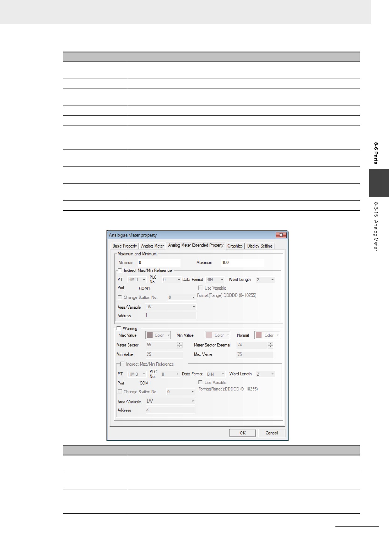
Switch to the [Analog Meter Component Extended Property] tab.
Descriptions of Analog Meter Component Extended Property
Maximum and
Sets the display range of the Analog Meter component to the constants.
Minimum
Indirect Max/Min
The upper limit value and lower limit value of displaying range for the analog meter will
Reference
be read from the value of specified address.
Warning
Checking it means the meter component displays by the color specifying the normal
range and warning range (the range exceeds the upper limit value and the range falls
the lower limit value).
3-145
3 Functions of NB-Designer
Descriptions of Analog Meter Component Extended Property
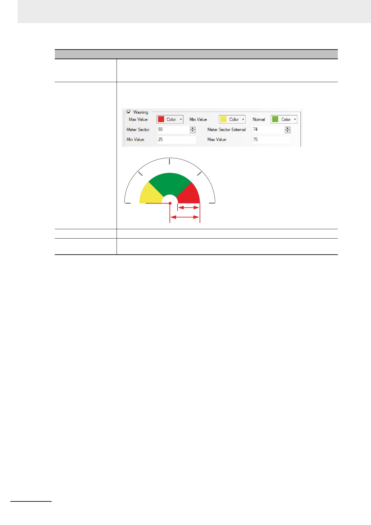
Meter Sector
Sets the thickness of the alarm range and the thickness of the fan block. The maximum
thickness can’t exceed the radius of the actual circle formed by the Analog Meter
component, but must be equivalent to or less than Meter Sector External
Meter Sector External
Sets the radius of the fan block. The maximum radius can’t exceed the radius of the
actual circle formed by the Analog Meter component, but must be equivalent to or
greater than the Meter Sector.
50
25
75
1) Meter Sector
2) Meter Sector External
0
100
1)
2)
Max Value/Min Value
Sets the normal range of the Analog Meter component to constants.
Indirect Max/Min
Sets the normal range of the Analog Meter component to variables, and specifies the
Reference
memory address for reading data.
4
Switch to the [Graphics] tab and select the Vector Graphics or bitmap representing the
touching area and touching state.
5
Press the [OK] button to complete the setup of the Analog Meter component.
3-146
3 Functions of NB-Designer
3-6-16
Indirect Screen
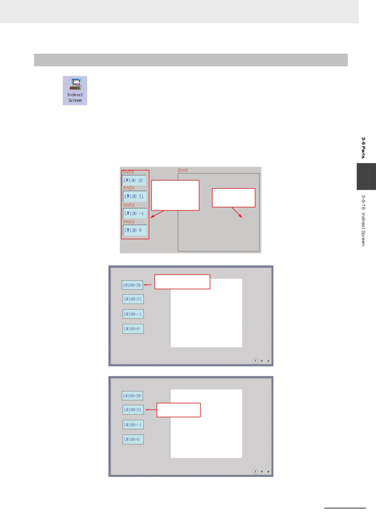
Indirect Screen can make an already created screen pop up on the current screen. Please
refer to [3-4-3 Screen Creation]. Generally, the screen called by the Indirect Screen is smaller than the
full screen (but it can also be of the same size as the full screen). In Indirect Screen specifications, pop-
up displays the screen of the screen No. supporting the stored value of the word address specified to
the [Read Address]. The number arranging indirect screens is not restricted in NB-Designer, but the
pop-up screens can be displayed simultaneously up to 16 screens at max.
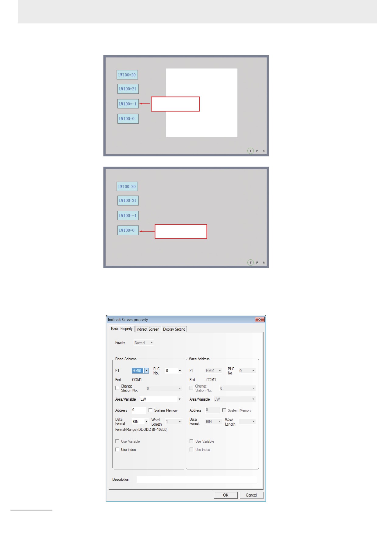
Value 0 is used to close the screen, and value -1 means to make screen 0 pop up, while the values
other than 0 or -1 mean to make the corresponding screens pop up.
3
Command Button,
write address is
Indirect screen,
LW100, setting
read address is
mode is
LW100.
"Set Constant"
Press this button,
pop-up screen 20
screen 20
screen 21
Press this button,
pop-up screen 21
3-147
3 Functions of NB-Designer
screen 0
Press this button,
pop-up screen 0
Press this button,
close indirect screen
z Process of adding one Indirect Screen component
1
Press the Indirect Screen component icon, drag it to the screen, then the [Basic Properties]
dialog box of the Indirect Screen component will pop up.
3-148
3 Functions of NB-Designer
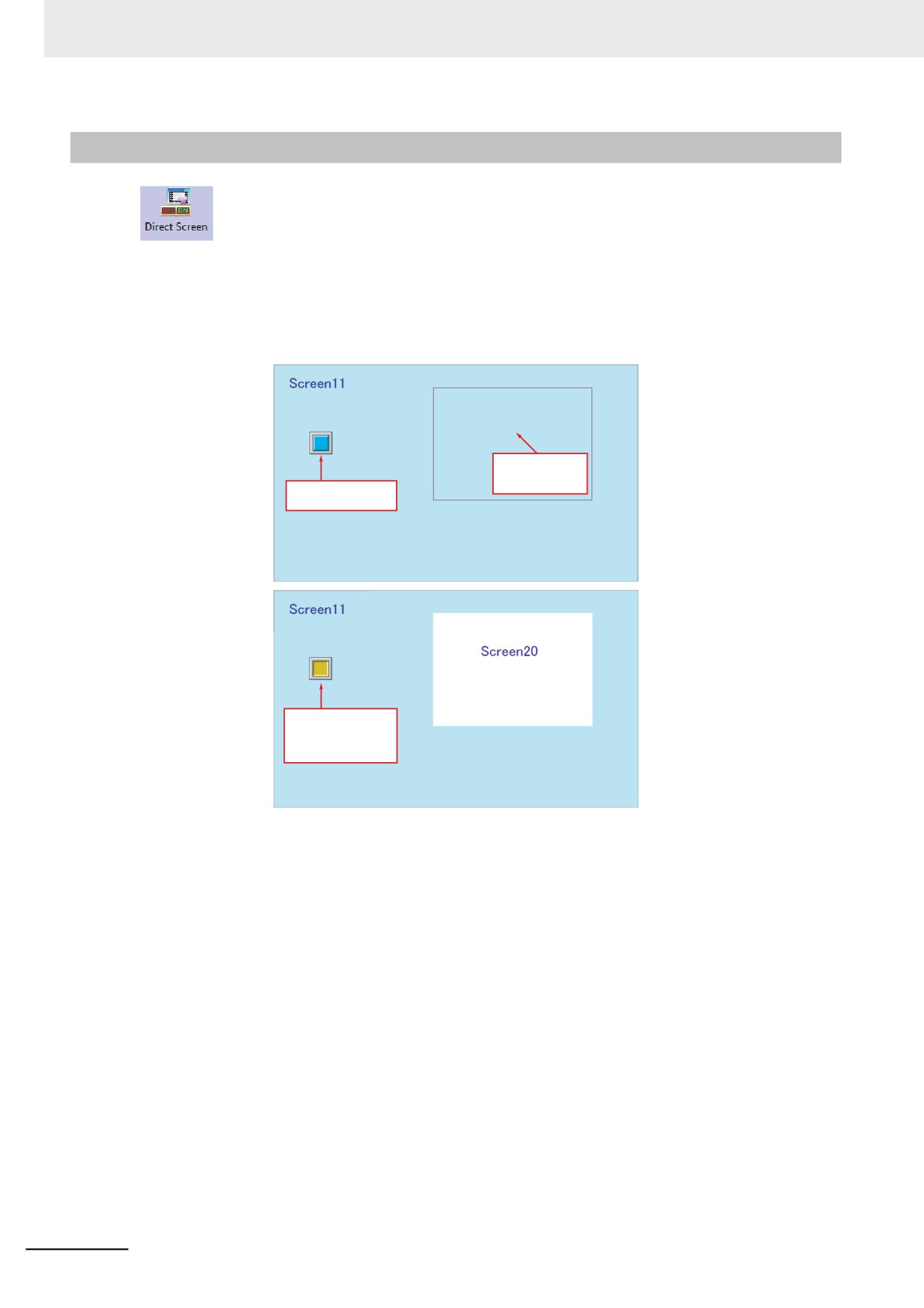
Read Address: It defines a display area and is able to display screen contents. The screen of
the No. supporting the stored address specified to the read address will be
displayed as pop-up screen. For example, if the value turns to 20, screen 20
will pop up (However, this screen must be created already.), while, when the
value turns to 0, the Pop-up Screen will be closed. If the pop-up screen is
closed using the function key, the value of the address specified to the read
address cannot be updated. When closing the pop-up screen, set “0” to the
read address.
Address: Specifies the word memory address storing the Indirect Screen No.
Word Length: Displays the data length of the read address, which is 1 by default.
2
Switch to the [Indirect Screen] tab and specify the displaying position of the screen which is
displayed in the pop-up screen specified by the [Indirect Screen] and check “Indirect Reference
of Display Position” for the Indirect Screen.
Indirect Reference of Display Position: Checking it means the position coordinates of the
3
popup Indirect Screen are read by the specified
memories; and Not-checking means the position
coordinates of the popup Indirect Screen will
depend on where the component is placed in the
screen.
X coordinate and Y coordinate are controlled by the specified address and the “specified
address + 1” respectively.
3
Press the [OK] button and properly adjust the position and the size of the Indirect Screen
component.
The size of the Indirect Screen limits the display area of the pop-up screens. The pop-up screen area
that goes beyond the Indirect Screen edge will not be displayed. Related function keys can be added to
move or minimize the screens (Refer to the “Pop-up screen title bar” and “Minimize” in 3-7-2 Function
Key (Page 3-201)).
Task Bar: If the pop-up screen comes with the [Pop-up screen title bar] and [Minimize] function keys,
each time a screen pops up, a small icon supporting the pop-up screen will be reserved for
this screen in the task bar. Pressing the small icon for this screen will push the
corresponding screen to the top of the screen. Pressing the icon for the second time will
minimize the screen, and another click will restore it to its initial state.
3-149
3 Functions of NB-Designer
3-6-17
Direct Screen
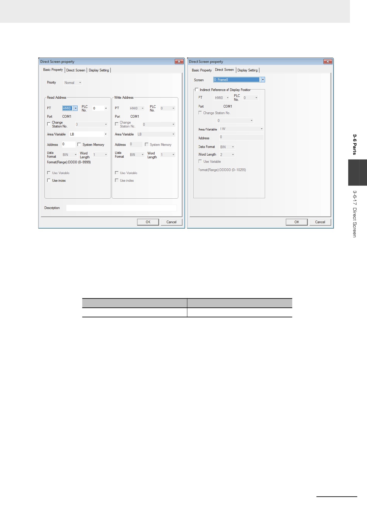
Direct Screen can make a specified screen pop up onto the current screen. The pop-up
screen will be displayed within the area of the [Direct Screen]. Normally, the Direct Screen size should
be set to same as that of the pop-up screen. There is no absolute limitation on the number of Direct
Screen. However, a maximum of 16 Direct Screens can be displayed simultaneously during operation.
The closing or opening of the Direct Screen is only determined by the bit address of the [Read Address]
that control it, while Function Key can’t be used to close it. When this bit address is ON, the screen will
pop up, and when it is OFF, the screen will be closed.
Direct screen, read
address is LB11,
screens No. is 20
Bit Switch, read/write
address is LB11
Press this button, set
all the bit of read/wirte
address memery to '1',
and popup screen 20
z Process of adding one Direct Screen component
1
Press the Direct Screen component icon, drag it to the screen, then the [Basic Properties]
dialog box of the Direct Screen component will pop up.
Read Address: When the specified read address is ON, the content of the specified screen
will be displayed in the Direct Screen component area.
If the pop-up screens is closed using a function key, the value of the address
specified by the read address cannot be turned OFF. When closing the pop-
up screen, set “0” to the read address.
3-150
3 Functions of NB-Designer
Address: Specifying the address controlling the display of the pop-up screen.
3
2
Switch to the [Direct Screen] tab and select the Destination Screen No. to be ejected in
[Screen].
Indirect Reference of Display Position: Checking it means the position coordinates of the
popup Direct Screen are read by the specified
memories; and Not-checking means the position
coordinates of the popup Direct Screen will depend
on where the component is placed in the screen.
X Coordinate of Pop-up Screen
Y Coordinate of Pop-up Screen
First address
First address + 1
The position of the pop-up screen is controlled by 2 memories, i.e. the X coordinate is
controlled by the First address, while the Y coordinate is controlled by the “First address + 1”.
But for some special PLCs (such as S7-200 etc.), the address must be an even number. For
example, VW80 is the memory controlling X coordinate, and VW82 is that controlling Y
coordinate.
3
Press the [OK] button to complete the setup, and adjust the position and the size of the Direct
Screen component. The size of the screen will limit the display area. The pop-up screen area
that goes beyond the Direct Screen edge will not be displayed. Function keys can be used to
move or minimize the screens. Please refer to the contents related to the function key such as
“Pop-up screen title bar” and “Minimize”, etc. in 3-7-2 Function Key (Page 3-201).
3-151
3 Functions of NB-Designer
3-6-18
Alarm
The Alarm component will display all the alarm information enabled in the set area. The
content it displays is the same as that displayed by the Alarm Display, and both of them are about the
alarm information of a certain node switch (bit address). When the bit address which worked as alarm
trigger is released, the alarm display will be removed. The alarm information displayed by the alarm is
necessarily registered by “Alarm Setting”. When multiple alarms occur, the alarms will be displayed in
the order descending to the newer (the top is the oldest and the bottom is the newest).
z Process of adding one Alarm component
1
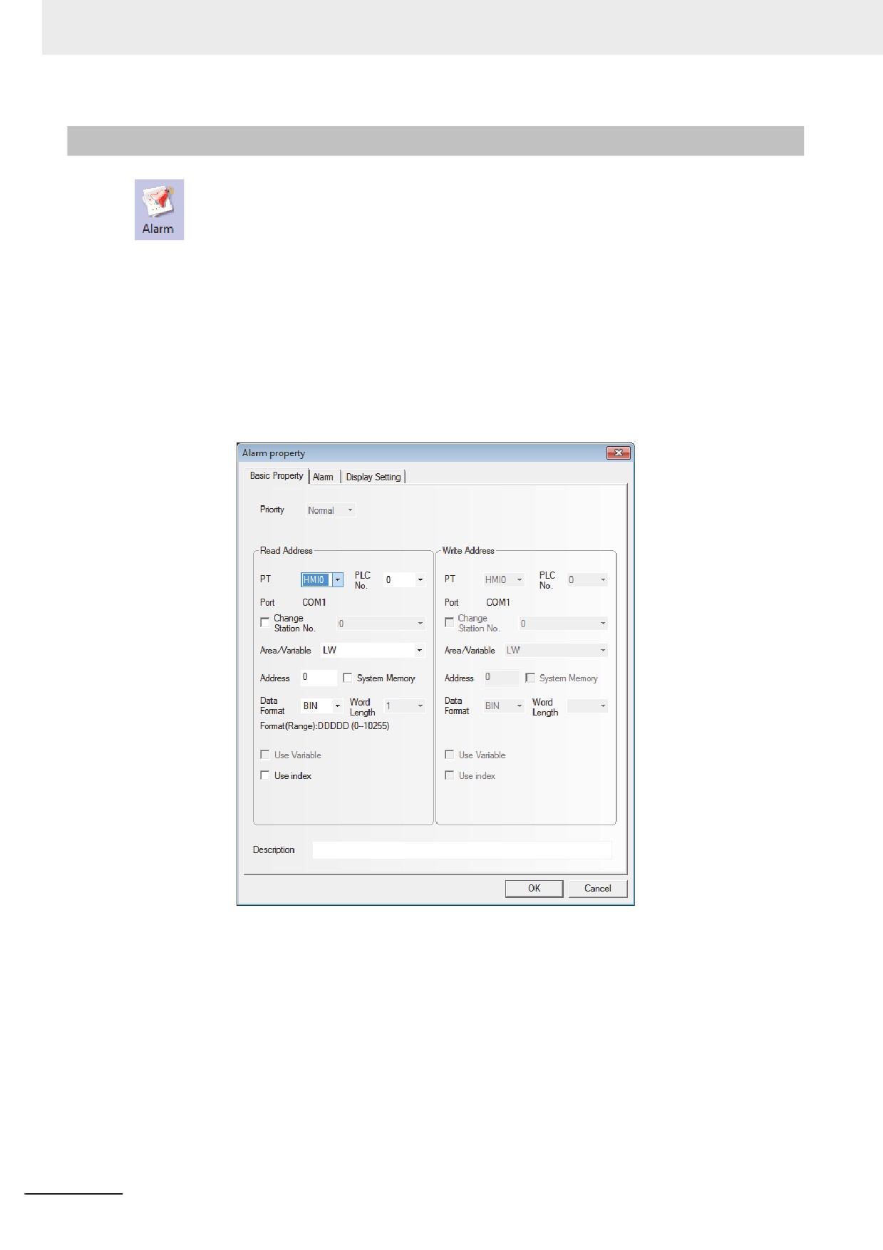
Press the Alarm component icon, drag it to the screen, then the [Basic Properties] dialog box of
the Alarm component will pop up.
Read Address: The address specifying the display of the alarm is specified. All the alarm
information is displayed from the latest to the oldest, i.e. if the value of the read
address is N, the Nth alarm will be displayed on the first line, the alarm of the
smaller No. than N will be removed.
Address: Refers to the word address using for controlling display.
Word Length: Displays the data length of the read address, which is 1 by default.
3-152
3 Functions of NB-Designer
2
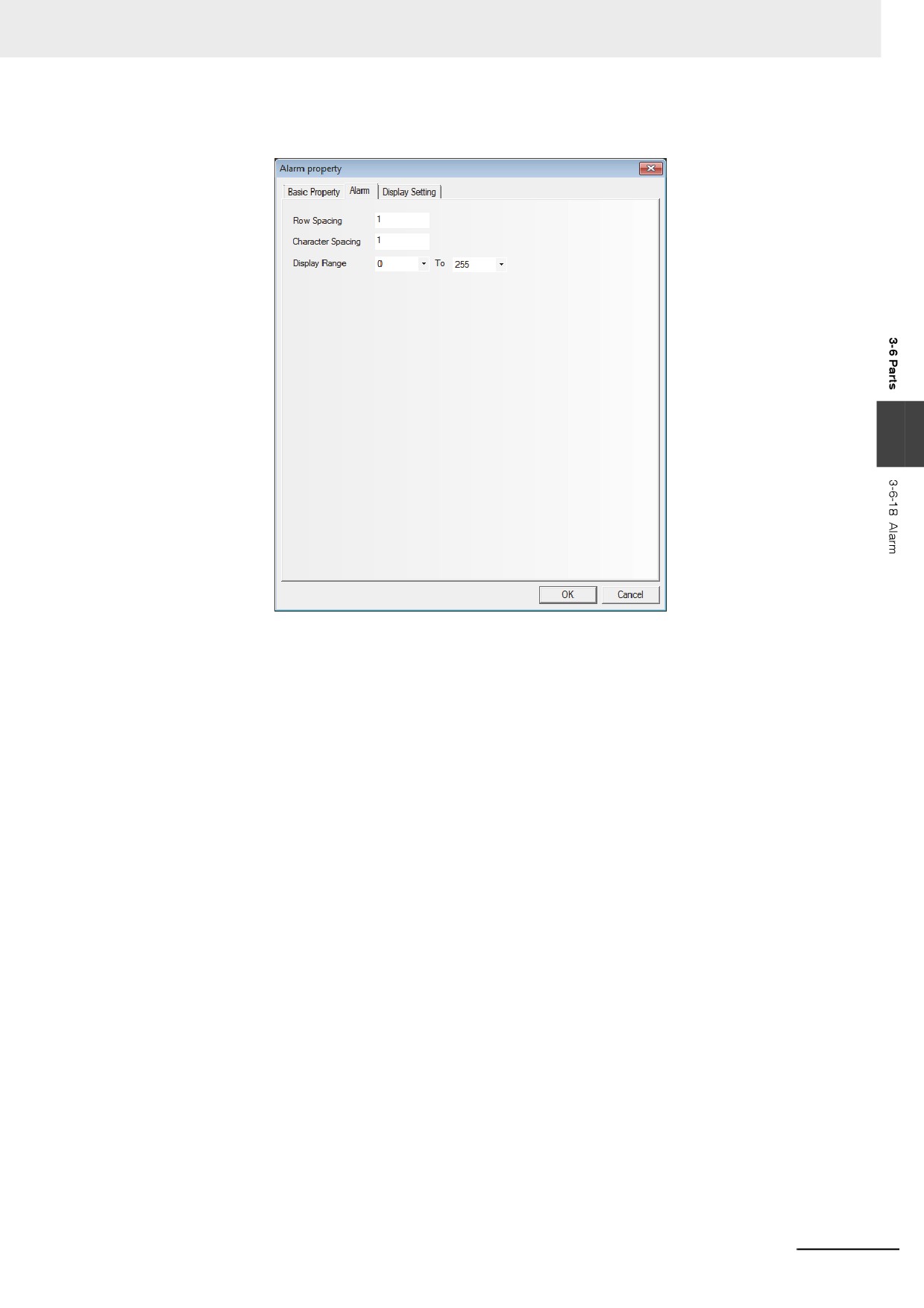
Go to the [Alarm] tab, as shown below:
3
Row Spacing and Character Spacing: Specifying the row space and character space of the
displayed alarm. Graphic font ignores this setting.
Display Range: “0 To 255” are available. When memory the alarm information, you need to
assign a type for each piece of alarm information. For example, 3 pieces of
information are registered, with 0, 1 and 2 as their types. Add an Alarm
component in the screen, and set the [Display Range] to “0 To 1”. Then when
all of the 3 alarms occur, set to the Type0 and Type1 will be displayed in the
screen.
3
Press the [OK] button to complete the setup, and adjust the position and the size of the Alarm
component.
3-153
3 Functions of NB-Designer
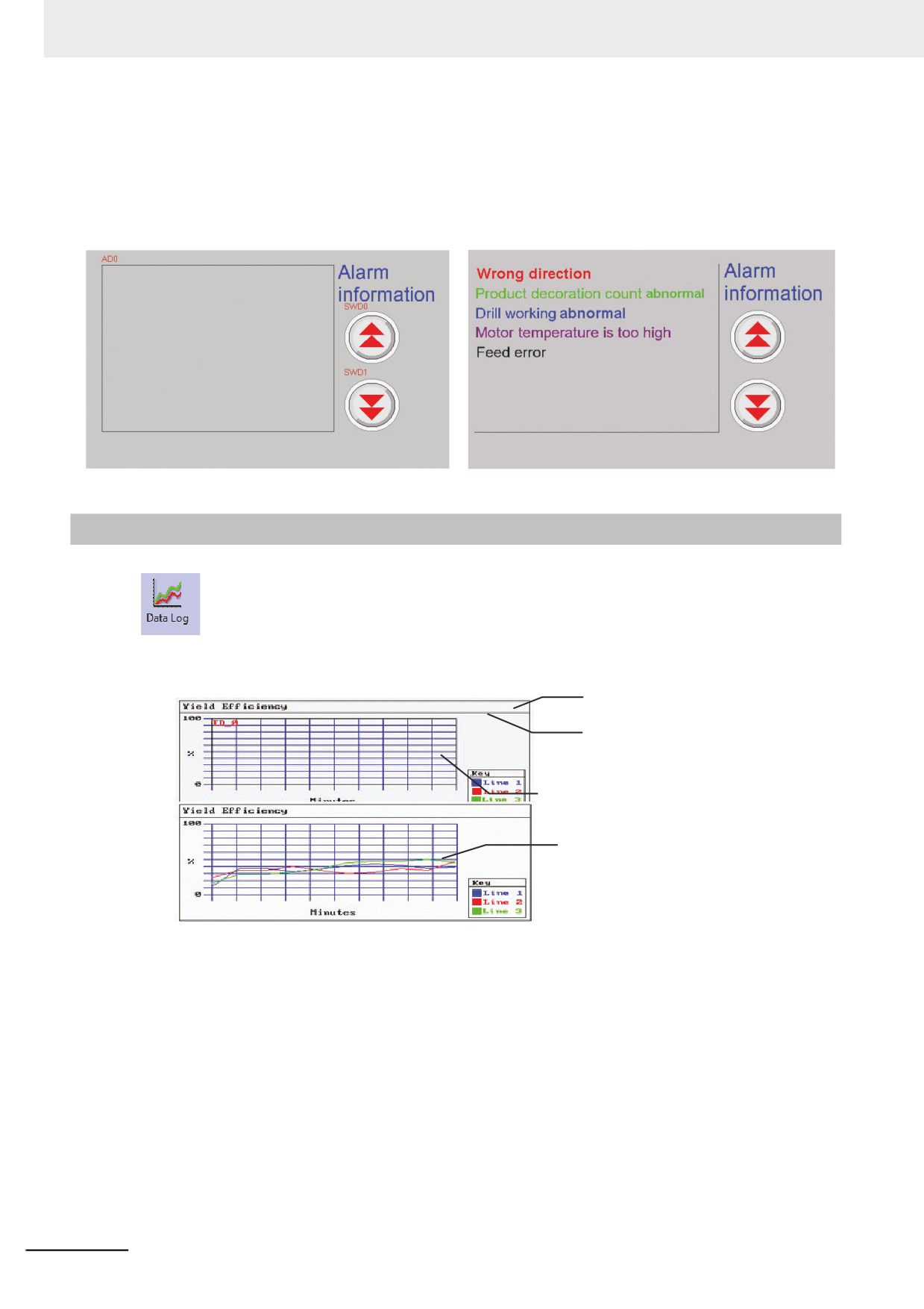
z Example of Alarm component
Use a Vector Graphics (VG0) as the rectangle background and another Vector Graphics (VG1) as
the sunken display area. Use 2 Command Button components (SWD0, SWD1) to increase or
decrease the starting lines of alarm information displayed (i.e. controlling the increase or decrease
of the “Read Address” data). Two command button components (SWD0 and SWD1) allow the start
line No. ([Read Address] of the alarm) increased or decreased to scroll the displayed alarm.
3-6-19
Data Log
The Data Log component acquires some PLC data and displays it in the manner of a Data
Log at regular intervals. When each sampling period comes to an end, new data will be read from the
PLC and displayed on the right of the Data Log, which ensures the real-time display.
Vector Graphic
Scale
Trends
The latest data shows
on the left, and the
track moves right.
A typical example of Data Log is as above shown. Use one Vector Graphics as background, and use
the Scale component to express the information on the related Data Logs. Then place the Data Log
component above the Vector Graphics.
When the trend curve should be stored in the external memory, refer to 6-1-3 Data History, Data Log
and XY Graph (Page 6-7)
3-154
3 Functions of NB-Designer
z Process of adding one Data Log component
1
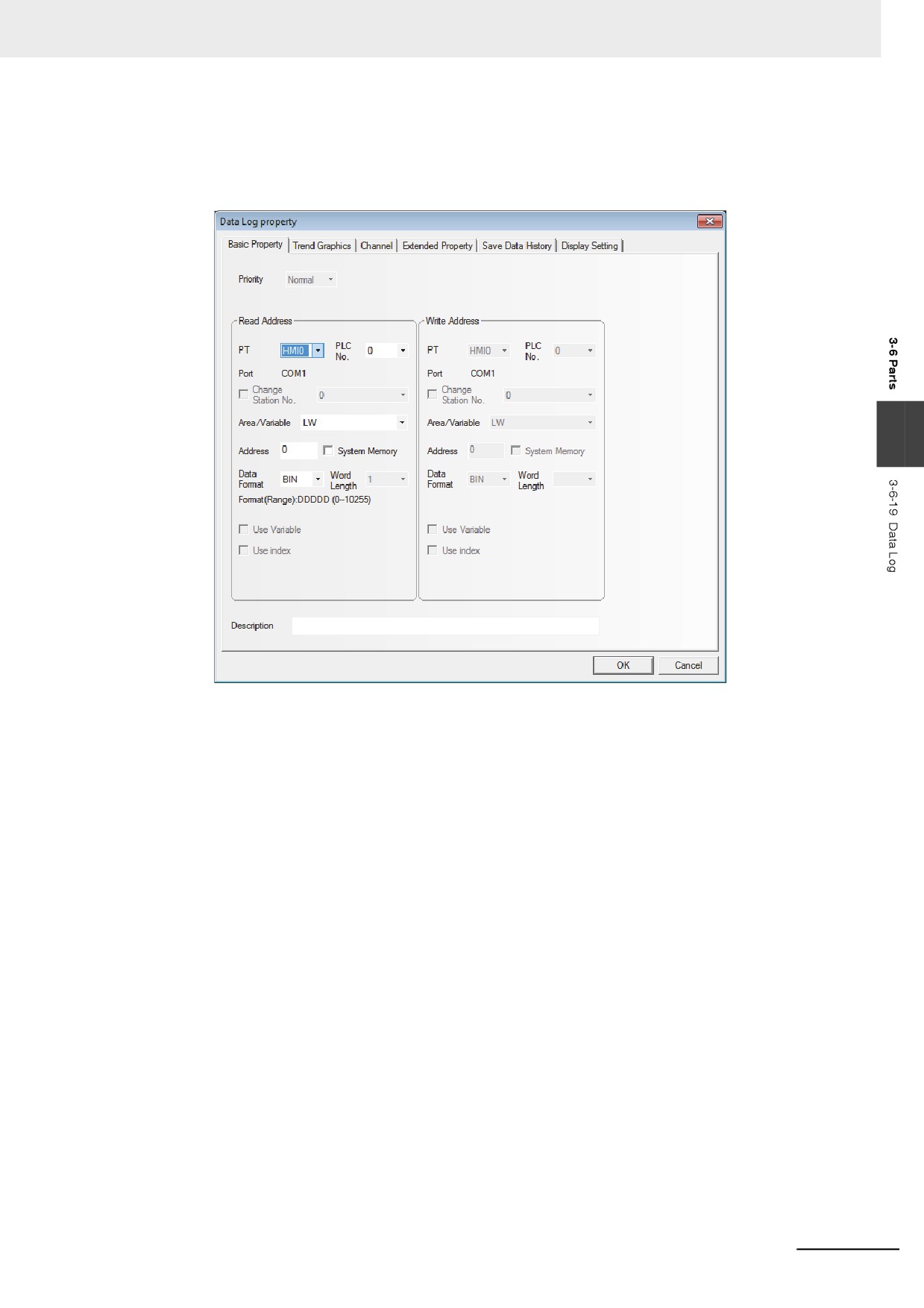
Press the Data Log component icon, drag it to the screen, then the [Basic Properties] dialog
box of the Data Log component will pop up.
3
Read Address: Refers to the word address of PLC corresponding to the 1st line data. And the
word address corresponding to the 2nd line is “Read Address + 1”, and the 3rd
line is “Read Address + 2” and so on.
Address: Refers to the first address of the word address corresponding to the Data Log.
Word Length: It is determined by the sampling channels and the storage format for each
channel. When the stored style of all the channel is signed 16-bit, if the channel
number is N (where, 1<=N<=16), the Word Length will be N.
3-155
3 Functions of NB-Designer
2
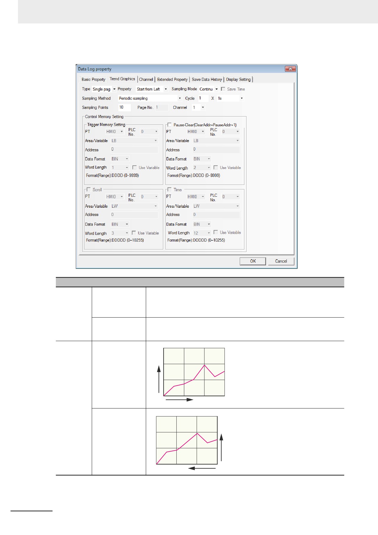
Go to the [Trend Graphics] tab and set the parameters related to the Data Log.
Descriptions of Data Log Properties
Type
Single page
Only the data change information of the sampling data in the current page is
displayed, and extension of Data Log is not allowed. In this style, the data
which data log was updated and scrolled to be removed from the screen
cannot be retained. The extension of the data log is impossible.
Multiple pages
The extension of Data Log is possible. In this way, when the Data Log is
scrolled forward, the data displayed previously will be retained. The historical
data is stored in the memory for the reference in future.
Property
Start from Left
Y
O
X
Start from Right
Y
X
3-156
3 Functions of NB-Designer
Descriptions of Data Log Properties
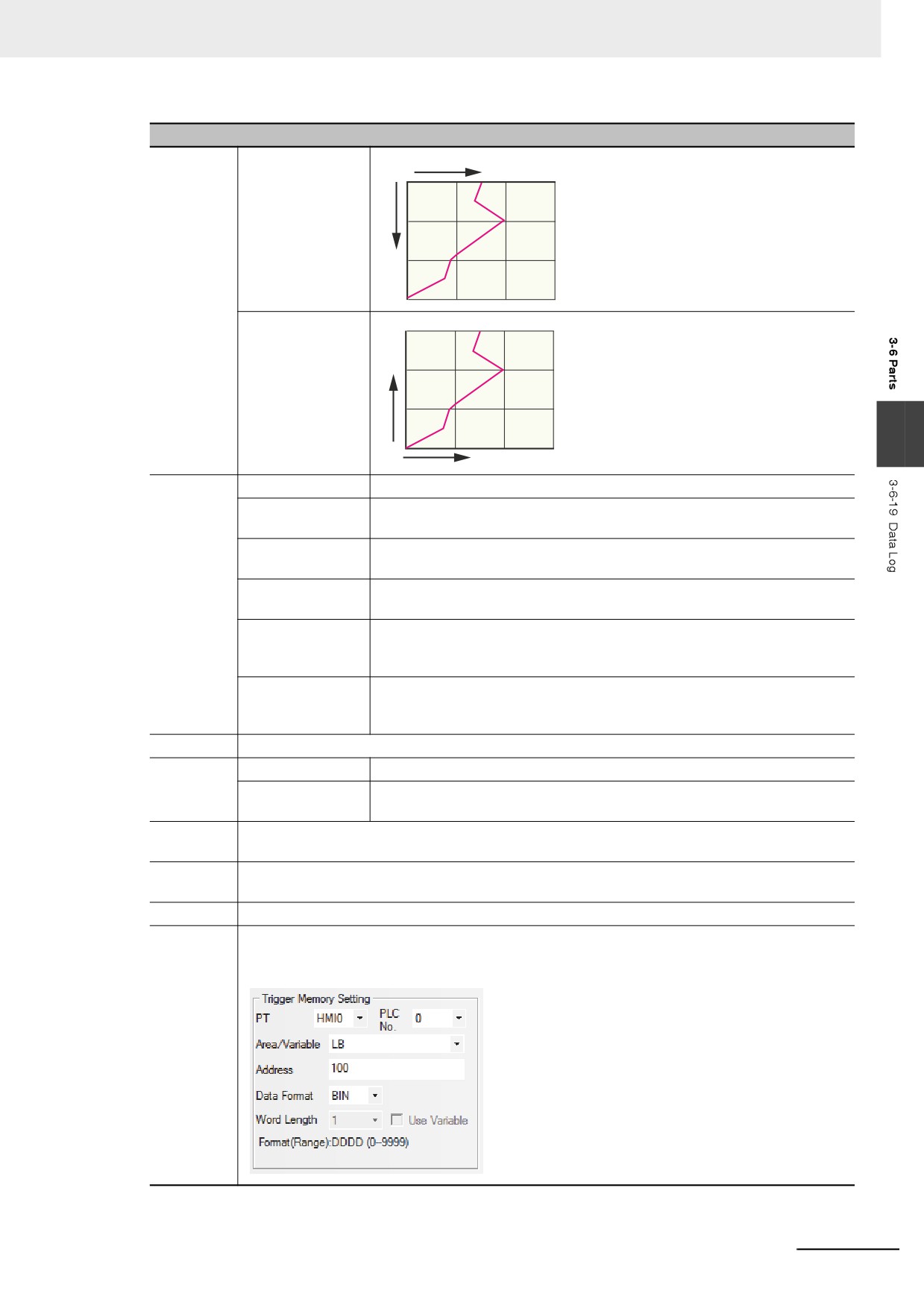
Property
Start from Top
Y
O
X
Start from Bottom
X
3
O
Y
Sampling
Periodic sampling
The data is sampled periodically.
Methods
OFF˘ ON trigger
When the state of the specified bit memory address turns ON from OFF, the
sampling
sampling is triggered.
ON˘ OFF trigger
When the state of the specified bit memory address turns OFF from ON, the
sampling
sampling is triggered.
OFF¯˘ ON trigger
When the state of the specified bit memory address changes, the sampling is
sampling
triggered.
OFF˘ ON reset
When the state of the specified bit memory address turns ON from OFF, the
trigger sampling
sampling is triggered, and the state of the specified bit memory will be set
automatically to be turned OFF after the triggering.
ON˘ OFF reset
When the state of the specified bit memory address turns OFF from ON, the
trigger sampling
sampling is triggered, and the state of the specified bit memory will be set
automatically to be turned ON after the triggering.
Cycle
Setting the interval to perform sampling with the unit of “s” or “100 ms”.
Sampling
Continue
When all the sampling points end, the sampling still continues.
Mode
Once
When all the sampling points end, the sampling will stop, which means
sampling is only performed once.
Sampling
Refers to the number of sampling point displayed in each screen.
Points
Page No.
When the [Type] in the [Trend Graphics] tab is set to [Multiple pages], specify the number of page
displayed.
Channel
Refers to the number of the track line to be displayed. And the channel can be set is up to 16.
Trigger
It is valid when “Trigger sampling” is selected as “Sampling Methods”. As the parameters are set
memory
as follows, when the state change of the specified LB100 conforms to the settings in Sampling
Methods, the sampling will be triggered.
Setting
3-157
3 Functions of NB-Designer
Descriptions of Data Log Properties
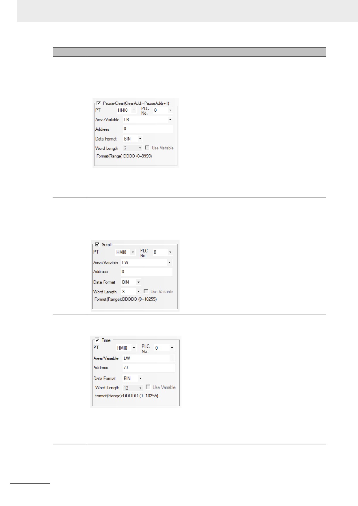
Pause-
The default Word Length is 2. “Pause” function only stops to refresh the changes in the curve
Clear
temporarily, and the sampling operation will not be stopped temporarily. When “Pause-Clear” is
checked as shown blow, and the state of the specified bit address LB0 is set “ON”, the screen will
stop refreshing temporarily When the specified bit address LB0 is set “OFF”, the changes in Data
Log will be refreshed and displayed.
“Pause” stop temporarily the update of the graph so that the sampling is stopped temporarily.
The address can be the trigger for “Clear” is “temporarily allocated address + 1”.
If the parameters are specified as above, the bit address LB0 functions as “Pause” and the bit
adress LB1 functions as “Clear”. Setting in this way, the displayed Data log screen can be cleared
only the changes occurred in LB1 state.
Scroll
The default value is 3. For example, if the specified memory is LW0, LW0, LW1 and LW2 will be
the current browsing index value (the newest data on the index value is 0 and the value is greater,
the data is older.), the starting browsing index value and the maximum browsing index value of
Scroll Bar respectively. This option is valid only when “Multiple pages” is selected. “Scroll” can be
used to browse the multiple Data Logs and can be in combination with the Scroll Bar. For the
specific using method of Scroll Bar, refer to 3-6-22 Scroll Bar (Page 3-168).
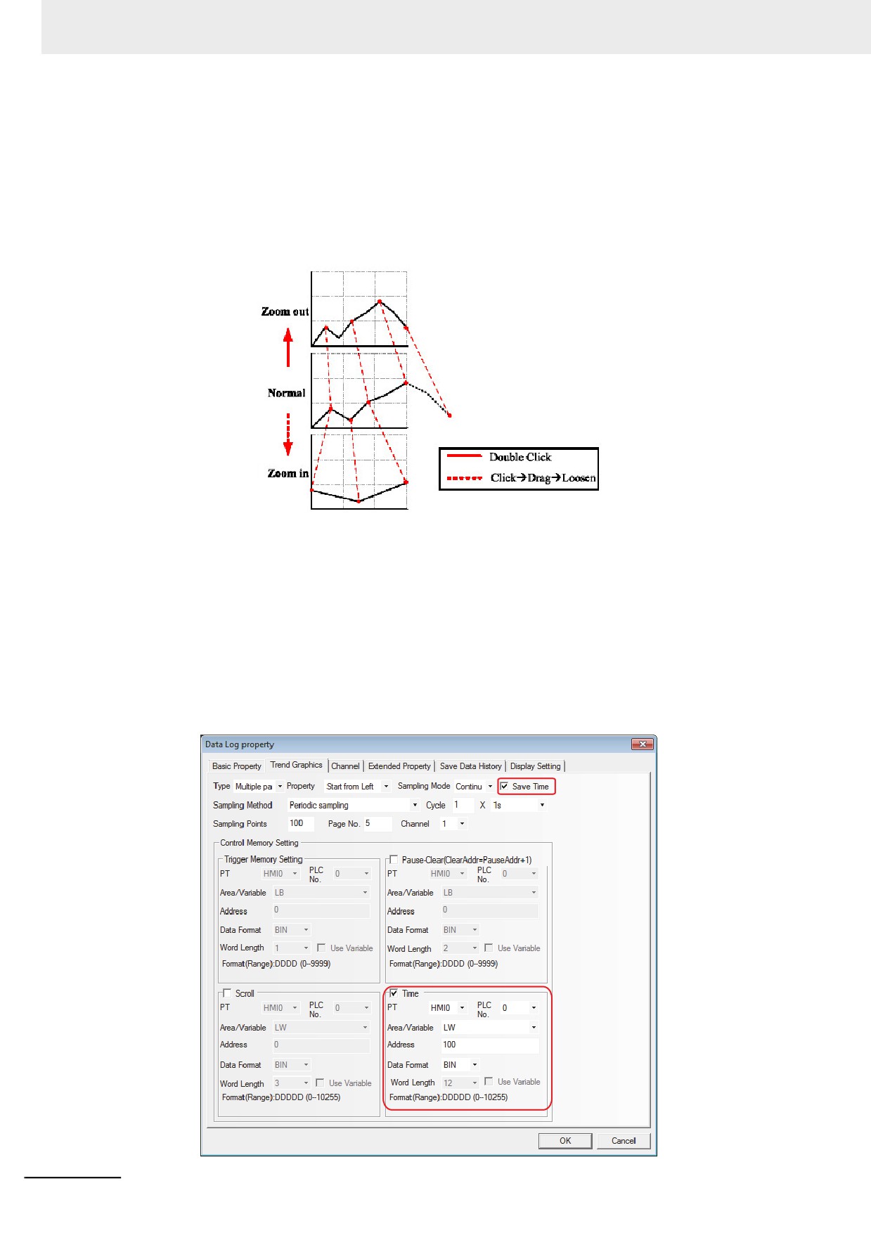
Time
It is used to save the time when the latest sampling point is performed. “Time” option in “Control
memory Setting” is valid only when the “Save Time” is checked. The default memory is LW and the
Word Length is 12.
As shown above, when the specified address is LW70, each data is stored as below:
• The sampling time of the oldest data within the displayed page
Second: LW70, Minute: LW71, Hour: LW72, Day: LW73, Month: LW74, Year: LW75
• The sampling time of the newest data within the displayed page
Second: LW76, Minute: LW77, Hour: LW78, Day: LW79, Month: LW80, Year: LW81
Note When the trigger sampling is used, if multiple samplings are performed at the same timing, only single value
might be acquired.
When such a state is assumed, place the Data Transmission component and others on the Common Sheet
and acquire the necessary data at local memory to perform the sampling for the local memory.
3-158
3 Functions of NB-Designer
3
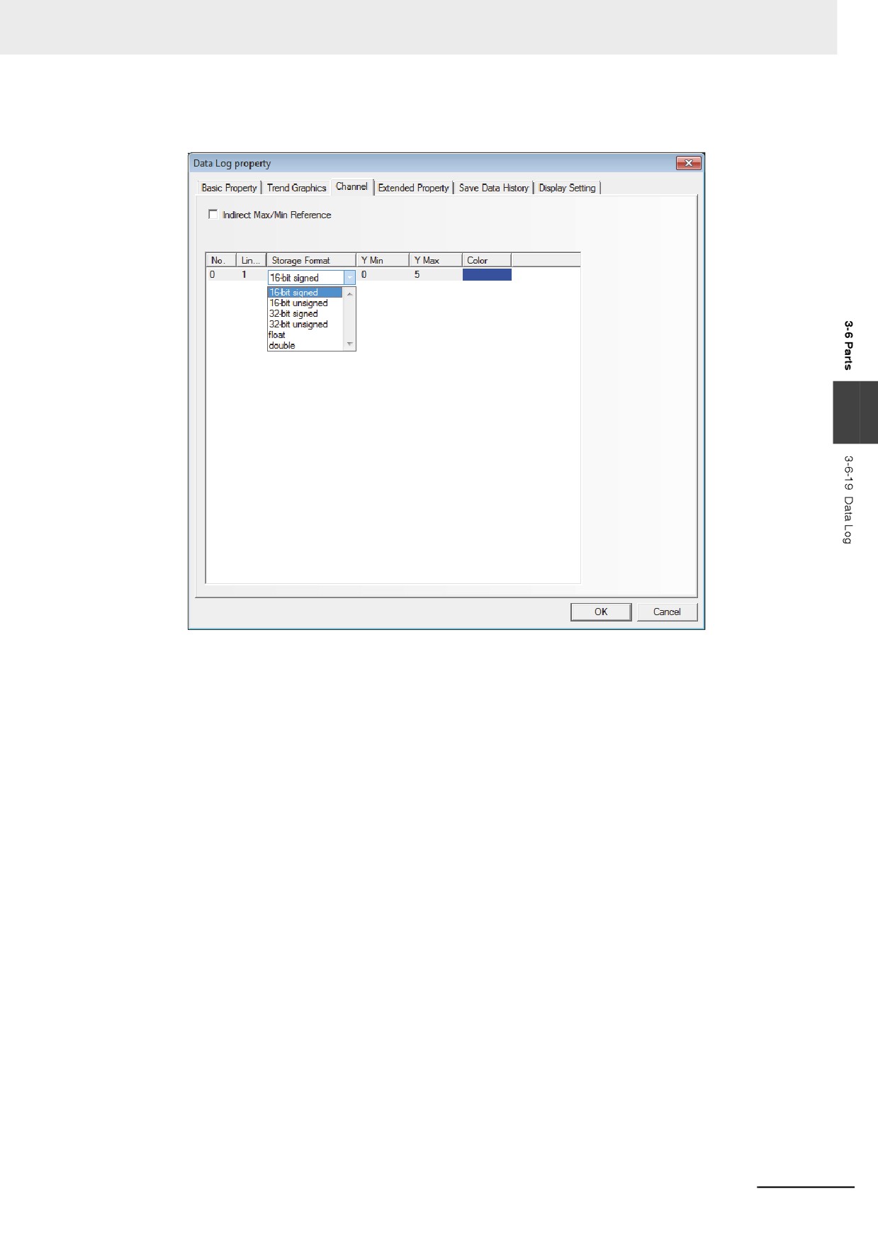
Switch to the [Channel] tab and set the parameters related to each track line.
3
Color: Specifies the color for each track line.
Line Width: Refers to the thickness of the line, and 8 kinds of line width are available here.
Storage Format: Sets the data type used by the user and 6 kinds are available.
Y Min/Y Max: Sets the minimum value and maximum value of the data corresponding to each
track line in Y direction.
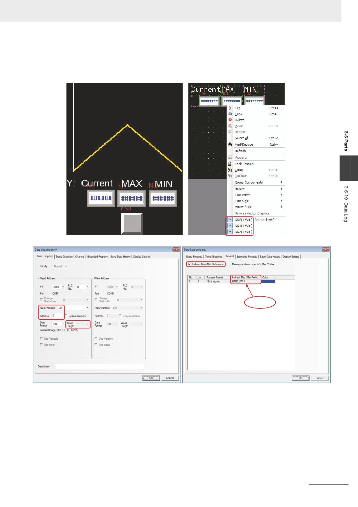
Indirect Max/Min Reference: Sets the display range of channel track to variable, and
specifies the memory address for reading range value. For the
multiple channels, the memory can be specified independently,
and [The Specified Indirect memory Address] is Y Min, and [The
Specified Indirect memory Address + 1] is Y Max.
3-159
3 Functions of NB-Designer
4
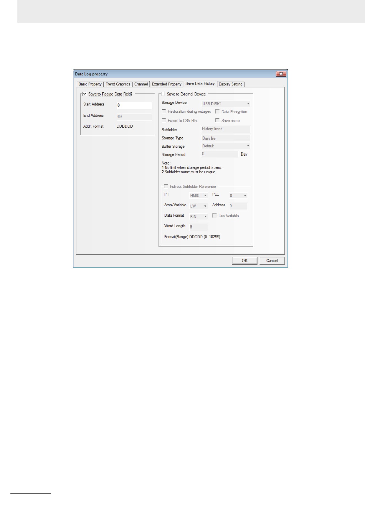
Switch to the [Save Data History] tab and determine whether to check “Save to Recipe Data
Field”.
Save to Recipe Data Field: After this option is checked and the Start Address. is set, the
sampling data can be saved to the Recipe Data Field(RW).
Data History for the Data Log is saved in the [Start Address] as the top, and the memory area
includes the Information Area with the size of 40 bytes (i.e. 20 words), and the Time Area with
the size of Sampling Pages × Sampling Points/Page × 4 words and the Data Area with the size
of Sampling Pages × Sampling Points/Page × Word Length.
When the multiple historical Data Logs saved into the recipe are used, the user must ensure
that the memory area of each trend curves will not overlap each other, otherwise, the data
mistakes will occur.
5
Press the [OK] button to adjust the position and size of the Data Log component.
3-160
3 Functions of NB-Designer
z Indirect Max/Min Reference of Data Log
Descriptions: LW0 represents the variable making sampling for the Y coordinate, and the horizontal
axis represents the Time Axis. And LW1 and LW2 correspond to the minimum value (lower limit of
Y) and the maximum value (upper limit of Y) respectively.
3
LW1: Y Min
LW0: Y Max
3-161
3 Functions of NB-Designer
z Checking and Zooming Functions
The zooming function can be enabled or disabled by the special system memory LB9110, i.e. the
zooming function will be valid when the LB9110 is turned ON and invalid when the LB9110 is turned
OFF. In order to use this function, it is necessary to set the [Type] option to “Multiple pages” and
[PageNum] option to more than 1 in the [Trend Graphics] tab respectively. With the LB9110 being
turned ON, zoom-out status of the curve can be checked only by double clicking on the Data Log, and
the zoom-in status of selected curve can be checked by clicking at the start point of the curve and
loosening it after dragging it to the end point of the curve.
z Query of Sampling Time
When LW9200 to LW9205 are used to store the time for sampling points, the user can place the
Number Display components corresponding to these addresses to display the time for sampling points.
Procedures:
1
Checking the [Save Time] option and [Time] check boxes ( Note this is not the sampled time) in
the [Trend Graphics] tab in the [Data Log Property] dialog box:
The [Time] option can be used to set the first address for saving the time, which covers 12-
word-length address for saving the starting time of the Data Log (the former 6 words) and the
time value of the current Data Log (the latter 6 words) in “ssmmhhddmmyyyy” format and BIN
Data Format respectively.
3-162
3 Functions of NB-Designer
2
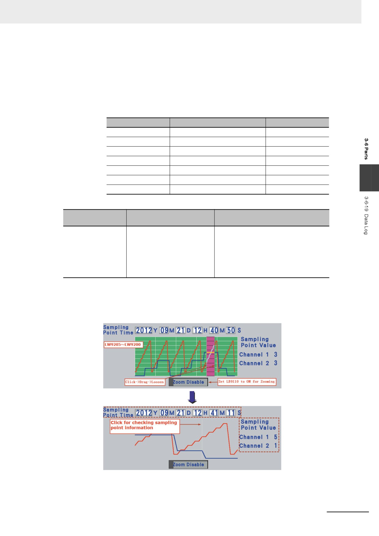
The function of query of sampling time is only enabled by LB9110 when the zooming function is
used. And when the LB9110 is turned ON, the zooming and checking functions can be
activated. When the above functions are enabled, even if the sampling is performed, the user
can choose the sampling point(s) in the real-time Data Log directly, and the time for sampling
point will be stored to LW9200 to LW9205 at this time. And the time query is also available with
the sampling point(s) from the Data Log being selected after the zooming in of one selected
section.
Description list of related addresses:
memory Address
Descriptions
Addr. Type
LB9110
Control bit of zooming function
Bit address
LW9200
Second
Word address
LW9201
Minute
Word address
LW9202
Hour
Word address
LW9203
Day
Word address
LW9204
Month
Word address
3
LW9205
Year
Word address
z Query of sampling point value
Addresses of Special
Function
Descriptions
memories
LW9210~ LW9210+N
Displays values of each channel
N represents the channel number, and the
of browsed points.
sampling value of browsed points for each
channel is stored. For example, if the
channel number is 2, the sampling value of
current browsed points for channel 1 will be
stored to LW9210, and that for channel 2
will be stored to LW9211.
z Example of checking the operation result of sampling point information
The following shows the checking of sampling point information after the Data Log with 2-channel data
is zoomed in:
3-163
3 Functions of NB-Designer
3-6-20
Recipe
Recipe component can realize the data transmission from the recipe memory of PT to PLC, or
vice versa. For details, refer to 3-12 Recipe Data (Page 3-343).
3-6-21
Oscillograph
The Oscillograph functions similarly to the Data Log, and the difference between them is as
follows: For the Data Log, the background communication still continue to do when the current screen
where the Data Log locates is closed, the sampling information before the switching can be obtained
when the Data Log is switched to at any time. But the data sampling of the Oscillograph is valid only in
the current page, which means the Oscillograph data will not be read but be lost each time when the
page is switched, and the data sampling will start from the beginning when the Oscillograph screen is
switched to. The advantages of Oscillograph are as follows: The user can monitor several waveforms
that don’t need to be recorded for the long period, and no background communication burden will be
brought. Meanwhile, the user can use the “Sampling Rate” function provided by the Oscillograph, the
combination with the PLC allows to change the frequency of sampling point instead of only being
limited on the frequency of 1s/sampling point.
z Process of adding one Oscillograph component
1
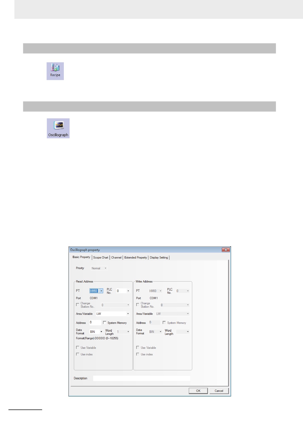
Press the Oscillograph component icon, drag it to the screen, then the [Basic Properties] dialog
box of the Oscillograph component will pop up.
3-164
3 Functions of NB-Designer
Read Address: Refers to the word address of PLC corresponding to the 1st graph. And the
word address corresponding to the 2nd graph is “Read Address + 1”, and the
3rd graph is “Read Address + 2” and so on.
Address: Refers to the first address of the word address corresponding to the graph.
Word Length: It is determined by the sampling channels. If the channel number is N (where,
1<=N<=16), the Word Length will be N.
2
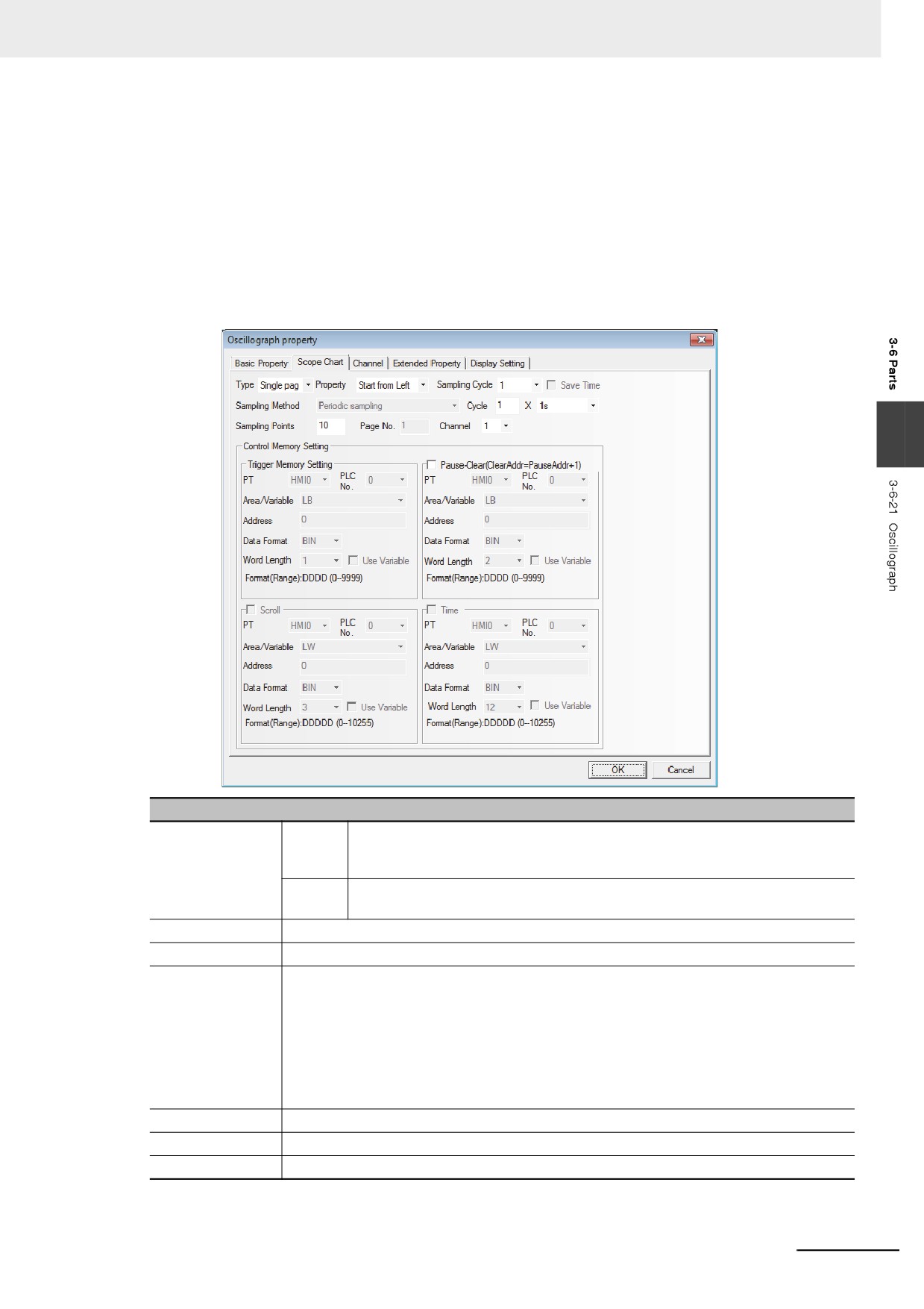
Go to the [Scope Chart] tab and set the parameters related to the Oscillograph component.
3
Descriptions of Scope Chart
Type
Single
Only the data change information of the sampling data in the current page is
page
displayed. In this type, the data which was scrolled and removed from the screen
will not be retained.
Multiple
The extension of Data Log is allowable. In this type, even if the Oscillograph is
pages
scrolled, the data displayed before the scrolling will be retained.
Property
Refers to the start movement direction of Oscillograph track.
Cycle
Refers to the interval to perform sampling with the unit of “s” or “100 ms”.
Sampling Rate
When the Sampling Rate is selected, the Oscillograph component will read the group data
with the sampling rate and display them at a time. For example, when the Read Address is
LW10, Sampling Rate is 2 and channel is 3, the values stored to the memory from LW10 to
LW15 for each sampling rate can be read. And the assignment is as follows: two of the data
is read for each sampling. The values will be read in the order of LW10, LW13 for channel
1, LW11, LW13 for channel 2, LW12, LW15 for channel 3. When the sampling time is 1 s,
the above-mentioned two group data will be read each second. And when the sampling
rate is used, the chart is more accurate and smooth.
Sampling Points
Refers to the number of sampling point displayed in each screen.
Page No.
This option is valid only when “Multiple pages” is selected.
Channel
Refers to the number of the graph to be displayed (16 channels at max.).
3-165
3 Functions of NB-Designer
Descriptions of Scope Chart
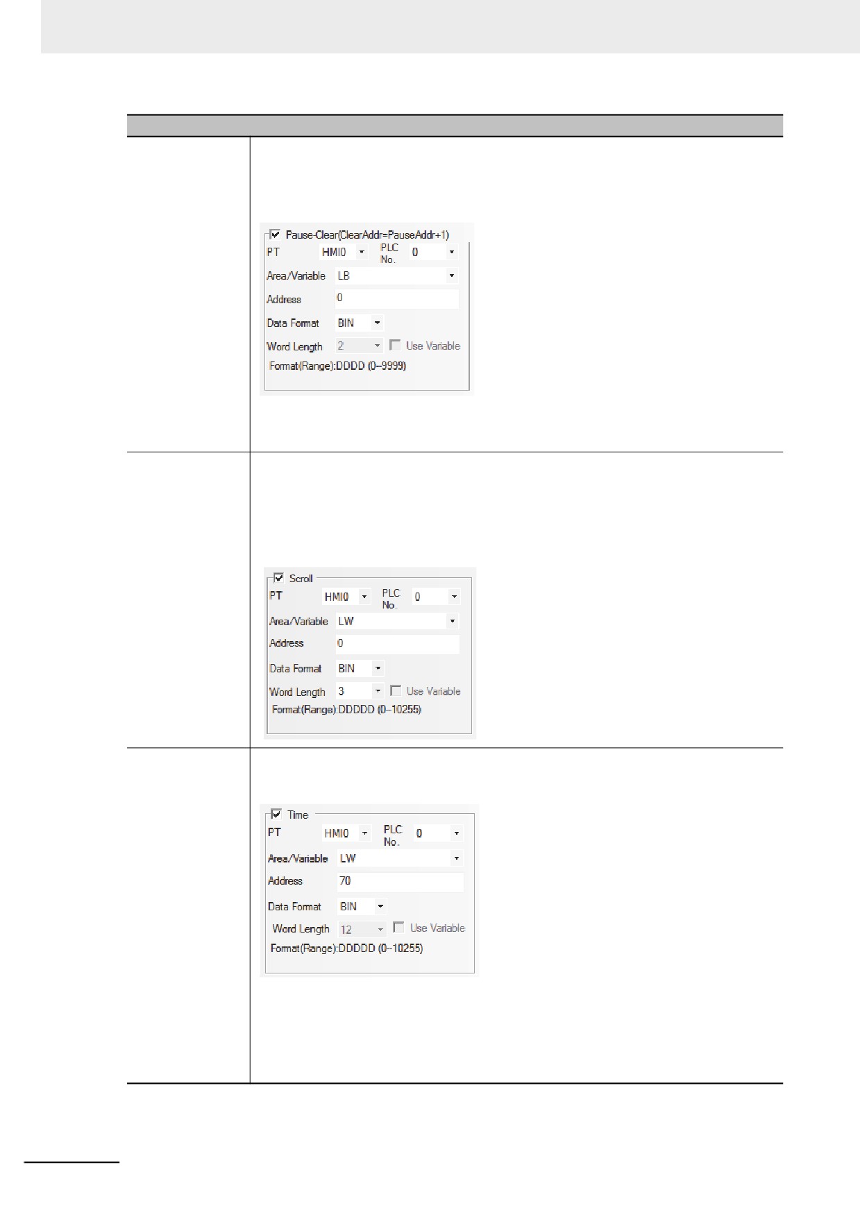
Pause-Clear
The default Word Length is 2. “Pause” function stops temporarily the refresh of the graph
and the sampling operation will not be stopped temporarily. When “Pause-Clear” is
checked as shown blow, and the state of the specified bit address LB0 is set “ON”, the
screen will stop refreshing temporarily When the specified bit address LB0 is set “OFF”, the
graph will be refreshed and displayed.
“Clear” corresponds to the “address allocated temporarily to Pause + 1”. Specifying the
parameters as above, the bit address LB0 functions as “Pause” and the bit address LB1
functions as “Clear”. Displayed graph can be cleared only the changes occurred in LB1 state.
Scroll
The default value is 3. For example, if the specified memory is LW0, LW0, LW1 and LW2
will be the current browsing index value (the newest index value is 0 and the value is
greater, the data is older), the starting browsing index value and the maximum browsing
index value of Scroll Bar respectively. This option is valid only when “Multiple pages” is
selected. “Scroll” can be used to browse the multiple graph and can be in combination with
the Scroll Bar. For the specific using method of Scroll Bar, refer to 3-6-22 Scroll Bar (Page
3-168).
Time
It is used to save the time when the latest sampling point is performed. “Time” option in
“Control memory Setting” is valid only when the “Save Time” is checked. The default
memory is LW and the Word Length is 12.
As shown as above, when the allocated address is specified to LW70, each data is stored
as below:
• The sampling time of the oldest data within the displayed page
Second: LW70, Minute: LW71, Hour: LW72, Day: LW73, Month: LW74, Year: LW75
• The sampling time of the newest data within the displayed page
Second: LW76, Minute: LW77, Hour: LW78, Day: LW79, Month: LW80, Year: LW81
3-166
3 Functions of NB-Designer
Note When the trigger sampling is used, if multiple samplings are performed at the same timing, only single value
might be acquired.
When such a state is assumed, place the Data Transmission component and others on the Common Sheet
and acquire the necessary data at local memory to perform the sampling for the local memory.
3
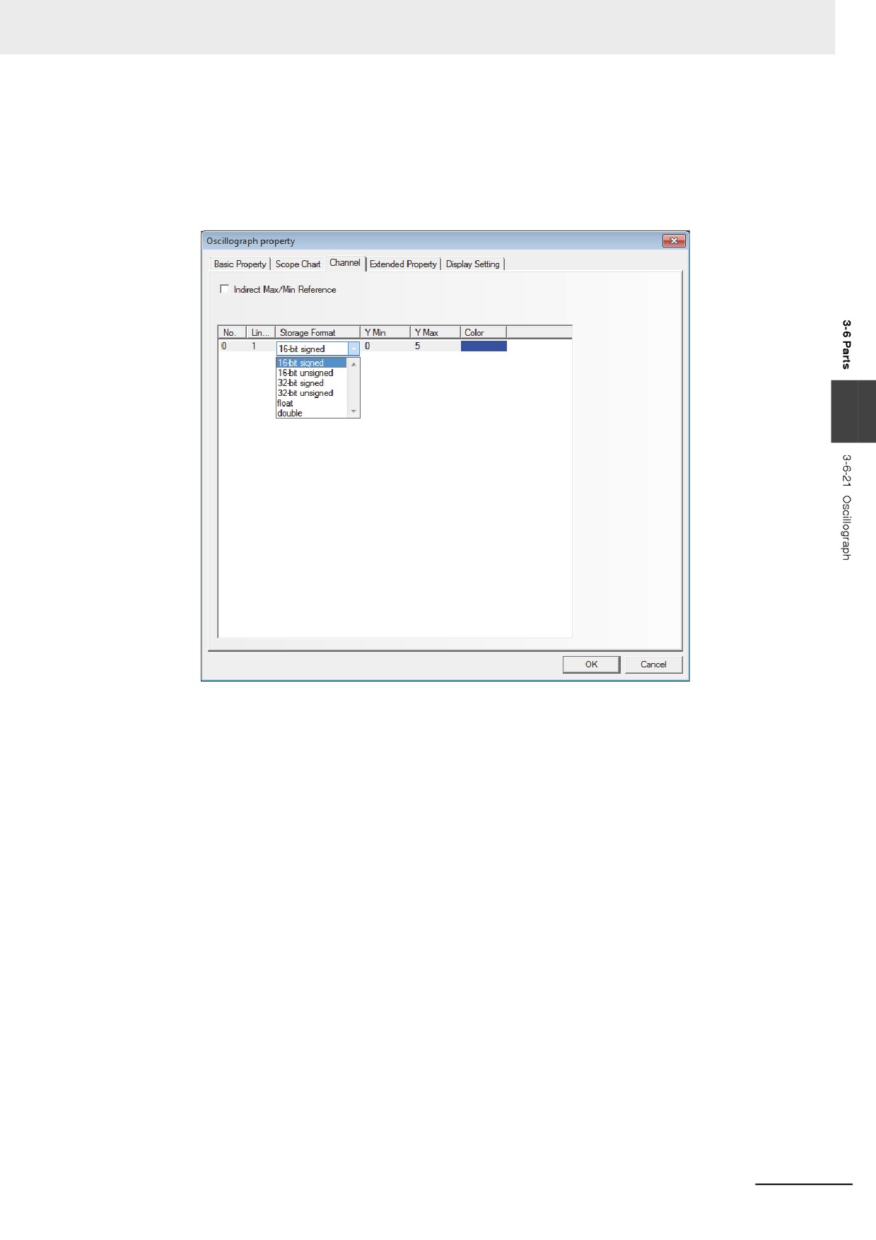
Switch to the [Channel] tab and set the parameters related to each graph.
3
Color: Specifies the color for each track line.
Line Width: Refers to the thickness of the line, and 8 kinds of line width are available here.
Storage Format: Sets the data type used by the user and 6 kinds are available.
Y Min/Y Max: Sets the minimum value and maximum value of the data corresponding to each
track line in Y direction.
Indirect Max/Min Reference: Sets the display range of channel track to variable, and
specifies the memory address for reading range value. For the
multiple channels, the memory can be specified independently,
and [The Specified Indirect memory Address] is Y Min, and [The
Specified Indirect memory Address + 1] is Y Max.
4
Press the [OK] button, and then adjust the position and size of the Oscillograph component.
3-167
3 Functions of NB-Designer
3-6-22
Scroll Bar
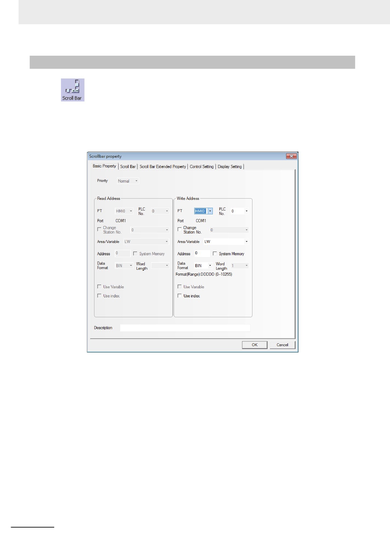
Scroll Bar is used to change the value in the specified word memory by pressing the slider.
z Process of adding one Scroll Bar component
1
Press the Scroll Bar component icon, drag it to the screen, then the [Basic Properties] dialog
box of the Scroll Bar component will pop up.
Write Address: Refers to the address of word memory of the current browsing index value for
the Scroll Bar component.
Address: Refers to the first address of the word address corresponding to Scroll Bar.
Word Length: Displays the data length of the write address, which is 1 by default.
3-168
3 Functions of NB-Designer
2
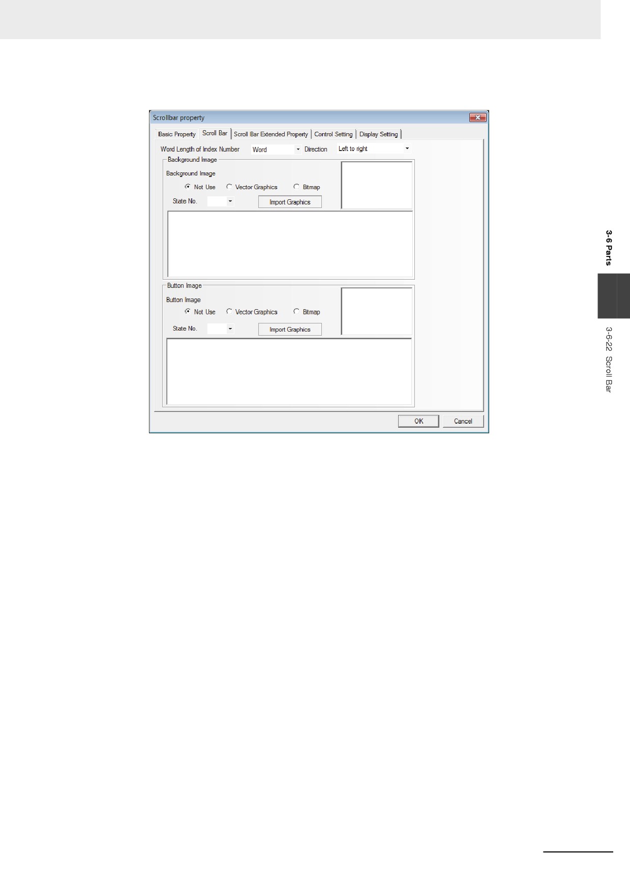
Go to the [Scroll Bar] tab.
3
Word Length of Index Number: Word and double-word are available.
Direction: Refers to the moving direction of the Scroll Bar, and it includes “Left To Right”,
“Right To Left”, “Up To Down” and “Down To Up”.
Background Image: Refers to the background images used by the Scroll Bar. It includes “Not
Used”, “Vector Graphics” and “Bitmap”. If “Vector Graphics” or “Bitmap”
is selected, you can select the Vector Graphics or bitmap you want to
use in “Image”, and you can also select the State Number corresponding
to the Vector Graphics or bitmap mentioned above.
Button Image: Refers to the button images used by the Scroll Bar. It includes “Not Used”,
“Vector Graphics” and “Bitmap”. If “Vector Graphics” or “Bitmap” is selected,
you can select the Vector Graphics or bitmap you want to use in “Image”, and
you can also select the State Number corresponding to the Vector Graphics or
bitmap mentioned above.
3-169
3 Functions of NB-Designer
3
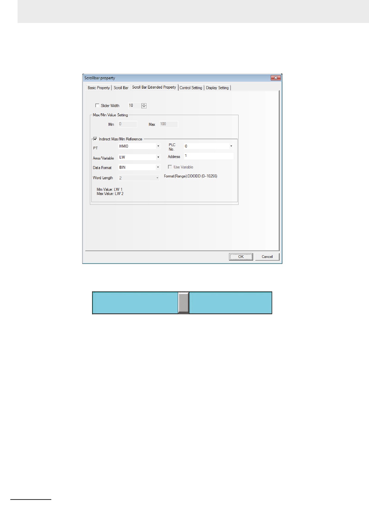
Go to the [Scroll Bar Extended Properties] tab and set the Slider Width and Indirect Max/Min
Reference.
Slider Width: Checking it means the slider width will be set by manual, and Not-checking it
means the slider width is 10 pixels by default.
Max/Min Value Setting:
Min: The lower limit of the Scroll Bar component is the starting browsing index value.
(-2147483648 to 2147483647 available)
Max: The upper limit of the Scroll Bar component is the maximum browsing index value.
(-2147483648 to 2147483647 available)
Indirect Max/Min Reference: Checking it means the starting browsing index value and the
maximum browsing index value of the Scroll Bar use the variables.
Assuming the address of the index memory is LW1, the addresses of the starting browsing
index value and the maximum browsing index value will be LW1 and LW2 respectively.
4
Press the [OK] button to complete the setup, and adjust the position and size of the Scroll Bar
component.
3-170
3 Functions of NB-Designer
3-6-23
Event
Event component is used to display the event information registered in “Event Setting” and
whose current state satisfying the triggering conditions. The Event component will display triggered
event information one by one according to the time sequence of the triggered event. If the accurate
time needs to be displayed, the RTC must be used or the Time must be read from the PLC.
If multiple events are triggered, the events will be displayed in the order of descending or the latest
event will be at the top and the oldest event at the bottom.
In addition, if 1024 events or more are triggered, the event will be deleted in order from the oldest event.
When only a particular event is displayed, there may be the cases where the event suddenly disappears
because of the hidden events of which the number has significantly increased to exceed 1024.
When the event should be stored to the external memory, refer to 3-10-7 Event History Setting (Page 3-
3
322)
z Process of adding one Event component
1
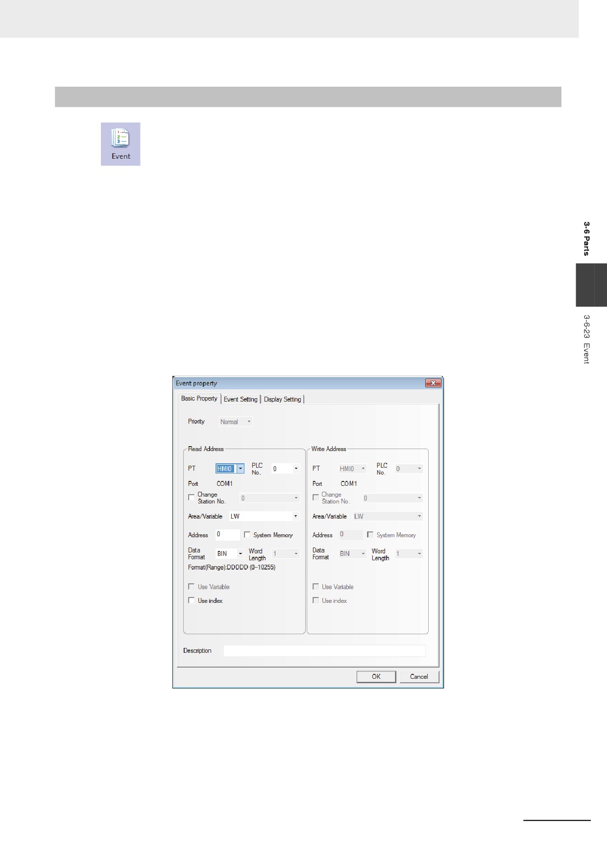
Press the Event component icon, drag it to the screen, then the [Basic Properties] dialog box of
the Event component will pop up.
Read Address: Refers to the address controlling the scroll of the event display. All the
information is classified according to the triggered time of the event, and the
new event is displayed on the top while the old event is displayed on the
bottom. For example, the value of the read address is N, the Nth event will be
displayed on the first line and the events on the lines with the smaller No. than
Nth line will be removed in the screen.
Address: Refers to the word address to support the controlling the scroll.
Word Length: Displaying the word length of read address (fixed as 1).
3-171
3 Functions of NB-Designer
2
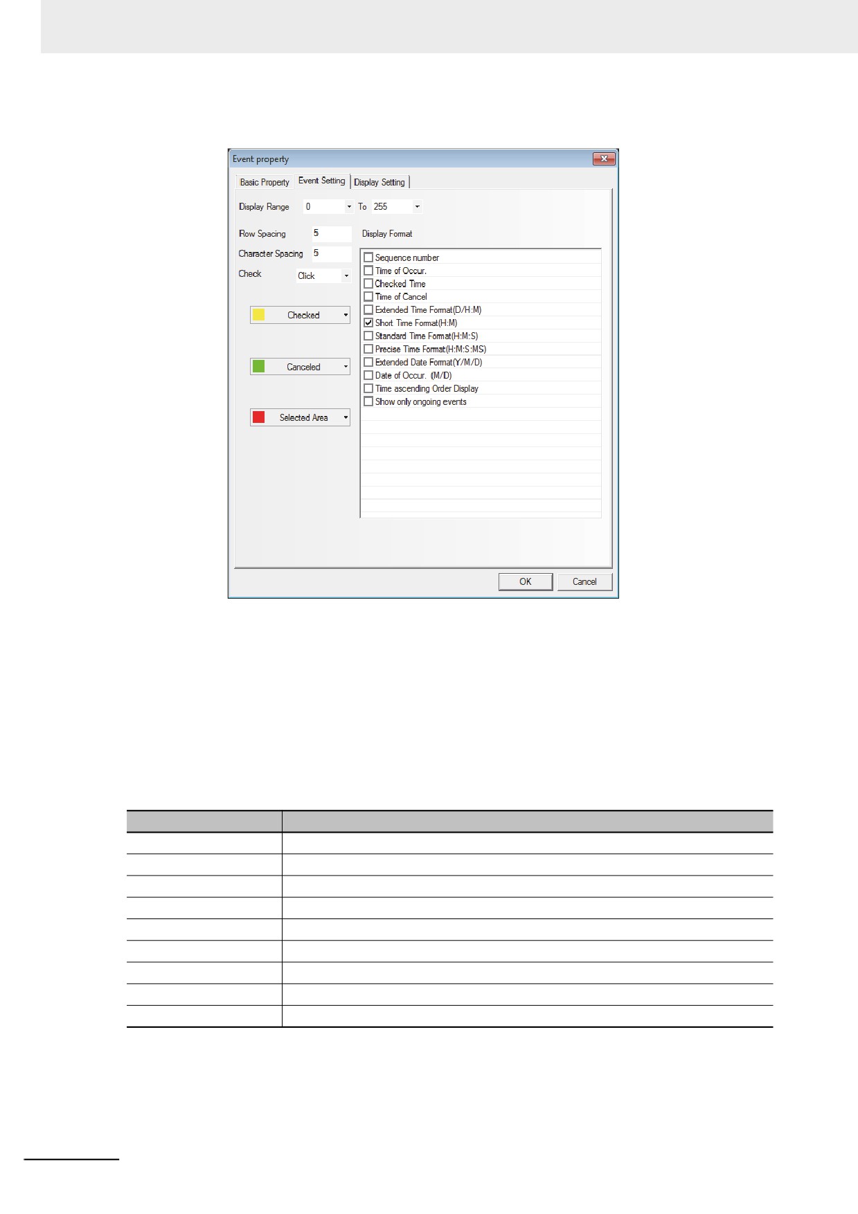
Go to the [Event Information] tab.
Row Spacing and Character Spacing: Refers to the distances between two neighboring lines
and characters. Graphic font ignores this setting.
Check: Includes the [Click] or [Double click].
Checked: Refers to the color after the event is confirmed.
Canceled: Refers to the color after the event is released.
Select Area: Indicates the color of the dotted line representing the selected area.
Display: Refers to the format of the Event Information Display. All the added contents (such as
Sequence No. and Event Trigger Time) are displayed in the front of the event
information.
Format Content
Descriptions
Sequence Number
Refers to the Event No. beginning from 0.
Time of Occur
The time when the event is triggered.
Checked Time
The time when the event is confirmed.
Time of Cancel
The time when the event is released. (i.e. returns to normal).
Extended Time Format
The time format is displayed as Day/Hour: Minute.
Short Time Format
The time format is displayed as Hour: Minute.
Standard Time Format
The time format is displayed as Hour: Minute: Second.
Precise Time Format
The time format is displayed as Hour: Minute: Second: Millisecond.
Extended Date Format
The data format is displayed as Year/Month/Date.
3-172