OMRON NB-Designer OPERATION MANUAL (NB-series, 2020) - page 6
3 Functions of NB-Designer
The descriptions of the Type are as follows.
X Axis Only
When this option is selected, the Moving Component can only move horizontally along X-axis
and the input maximum (minimum ) value is invalid and the Read Address and the Read
Address + 1 are used to store the component state and position respectively in this case.
Y Axis Only
When this option is selected, the Moving Component can only move vertically along Y-axis and
the input maximum (minimum ) value is invalid and the Read Address and the Read Address +
1 are used to store the component state and position respectively in this case.
X & Y Axis
When this option is selected, the Moving Component can move along X-axis and Y-axis, and
the Read Address, the Read Address + 1 and the Read Address + 2 are used to store the
component state, X-axis position and Y-axis position respectively.
X Scaling
When this option is selected, the Moving Component can only move horizontally along X-axis,
but the relative moving position can be set through the input value and proportional value (For
example, when the value of PLC to be read ranges from 0 to 1000, but the relative position to be
moved in the PT ranges from 0 to 640, the minimum values and maximum values of proportion
value and input value are 0 & 640 and 0&1000 respectively.) and the Read Address and the
Read Address + 1 can be used to store the component state and the position respectively.
Y Scaling
When this option is selected, the Moving Component can only move vertically along Y-axis, but
3
the relative moving position can be set through the input value and proportional value (For
example, when the value of PLC to be read ranges from 0 to 1000, but the relative position to be
moved in the PT ranges from 0 to 480, the minimum values and maximum values of proportion
value and input value are 0 & 480 and 0&1000 respectively.) and the Read Address and the
Read Address + 1 can be used to store the component state and the position respectively.
X Reverse
This option functions are similar with “X Scaling” but the component moves toward the opposite
Scaling
direction. When the value of position coordinate increases, the component moves leftward.
When it decreases, the component move rightward.
Y Reverse
This option functions are similar with “Y Scaling” but the component moves toward the opposite
Scaling
direction. When the value of position coordinate increases, the component moves upward.
When it decreases, the component move downward.
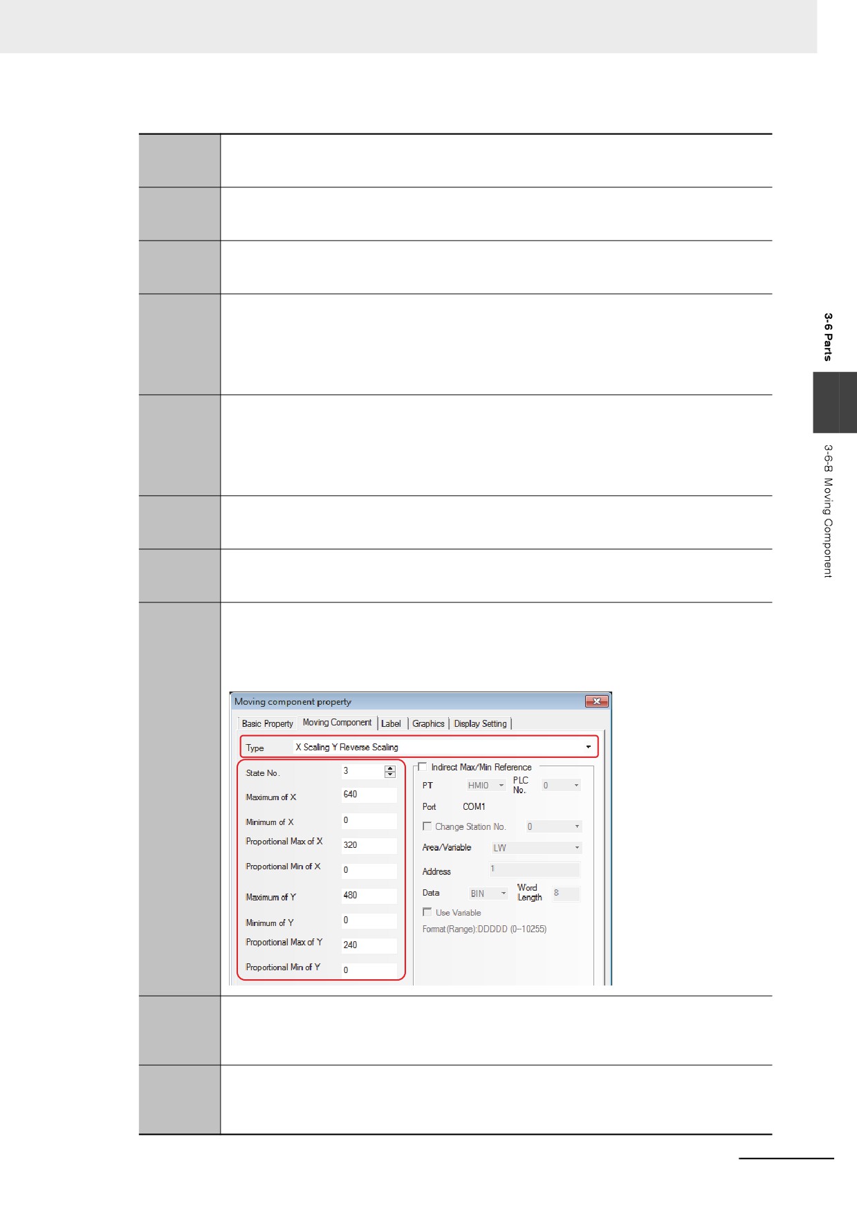
X Scaling Y
The Moving Component moves horizontally along X-axis and Y-axis, and the relative position can
Scaling
be set through the input value and the proportion value (For example, set the parameters as below.
When the stored PLC address specified to X axis ranges from 0 to 640, but should set the value to
be moved relatively in the range from 0 to 320 and the stored PLC address specified to Y axis
ranged from 0 to 480, but should set the value to be moved relatively in the range from 0 to 240.).
X Scaling Y
The Moving Component moves horizontally along X-axis and Y-axis, and the relative position
Reverse
to be moved can be set, and the component can move along the opposite direction of Y-axis.
Scaling
When the value of Y-axis is increased, the moving component moves upward, and when the
value of Y-axis is decreased, it moves downward.
X Reverse
The Moving Component moves horizontally along X-axis and Y-axis, and the relative position
Scaling Y
to be moved can be set, and the component can move along the opposite direction of X-axis.
Scaling
When the value of X-axis is increased, the Moving Component moves leftward and when the
value of X-axis in decreased, it moves rightward.
3-113
3 Functions of NB-Designer
X Reverse
The Moving Component moves horizontally along X-axis and Y-axis, and the relative position
Scaling Y
to be moved can be set, and the component can move along the opposite directions of X-axis
Reverse
and Y-axis. When the value of X-axis is increased, the Moving Component moves leftward,
Scaling
and when the value is decreased, it moves rightward. When the value of Y-axis is increased, it
moves upward and when the value is decreased, it moves downward.
When the Scaling is selected, the relation is as shown below.
Read
Minimum
Maximum
Minimum
(
-
)
×
(
-
)
Value
Input Value
Proportianal Value
Proportianal Value
Display Position=Current Position+
(Maximum Input Value-Minimum Input Value)
When the reverse scaling is selected, the relation is as shown below.
Minimum
Read
Maximum
Minimum
(
-
)
×
(
-
)
Input Value
Value
Proportianal Value
Proportianal Value
Display Position=Current Position+
(Maximum Input Value-Minimum Input Value)
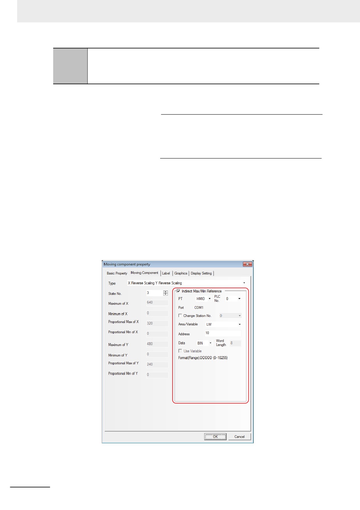
Indirect Max/Min Reference: The upper limits and lower limits of X-axis and Y-axis are
directly read from the memory address.
For example:
It is assumed that the type of the Moving Component is “X Reverse Scaling Y Reverse Scaling”
and the type of indirect address is LW10, then the Minimum of X and Maximum of X are the
values of LW10 and LW11 respectively, and Proportional Lower Limit of X and Proportional
Upper Limit of X are the values of LW12 and LW13 respectively, and the Minimum of Y and
Maximum of Y are the values of LW14 and LW15 respectively, and the Proportional Lower
Limit of Y and Proportional Upper Limit of Y are the values of LW16 and LW17 respectively.
as shown below.
3
Switch to the [label] tab and add the corresponding texts to be displayed.
3-114
3 Functions of NB-Designer
4
Switch to the [Graphics] tab and select Vector Graphics or bitmap to move or display the state.
5
Press the [OK] button to complete the setup of the Moving Component.
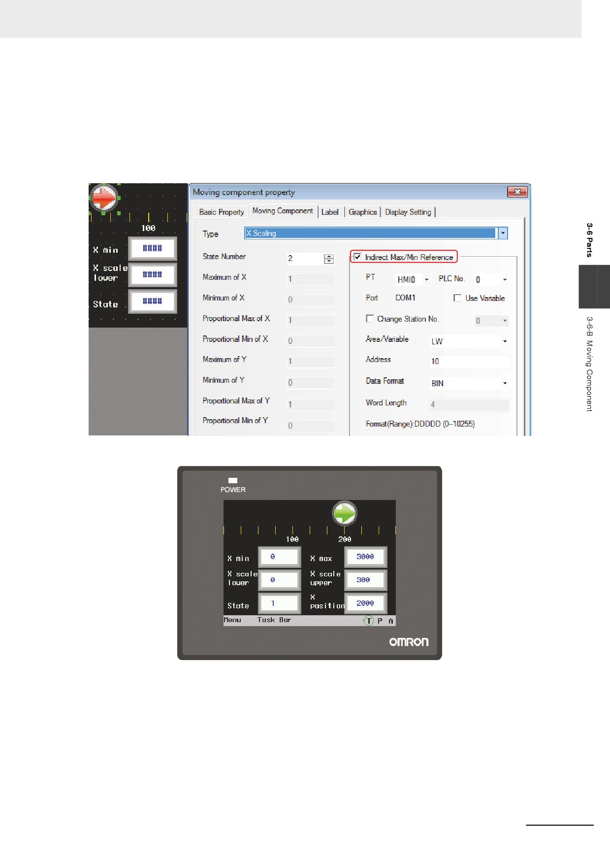
If it is Scaling Type, specify the Max/Min value.
The maximum value and minimum value of Moving Component supports Indirect Max/Min
Reference.
3
3-115
3 Functions of NB-Designer
3-6-9
Animation
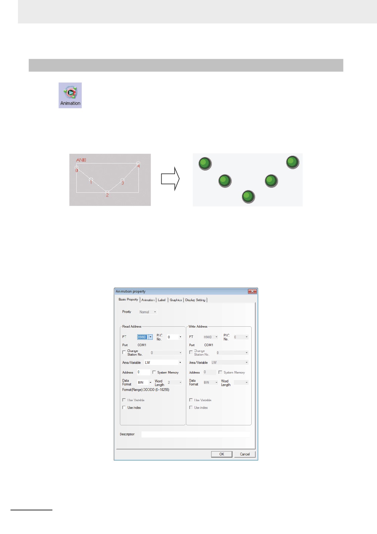
The Animation component is used to put the component into the position with the specified
track in the PT, and this position is determined by the preset path and the data of PLC. The status and
absolute position of the component in the PT is determined by the data in the 2 consecutive PLC
memories. Generally speaking, the Read Address and the Read Address + 1 are used to store the
state and the position in the preset path respectively. When the values in the position memory of PLC
(Read Address + 1) change, the Vector Graphics or bitmap will jump to the next position in the preset
path.
z Process of adding one Animation component
1
Click the Animation component icon and drag it on the screen.
2
Set the path and moving point for the component in the PT, left click the mouse one by one on
each moving node, and right-click the mouse after the setup of path and moving nodes to
complete the setup.
3
Enter the parameters in [Basic Properties] tab in the [Animation Property] dialog box.
Read Address: Refers to the word address controlling the state and label of the Animation
Component in PLC, and [Read Address + 1] refers to the word address
controlling the position of the Animation component. The data in the memory
will be converted into BIN or BCD format (Refer to the Word Lamp
component.). Here, [Word Length] is limited to 2.
3-116
3 Functions of NB-Designer
Read Address Assignment:The word address specifying the position on the path which was
set previously is set automatically to Read Address + 1.
Read Address
States of Vector Graphics or bitmap
Read Address + 1
Position No. in the preset path.
Address: Refers to the first address of the word address corresponding to the Animation
component.
Word Length: Displays the data length of the read address, which is fixed to “2”.
4
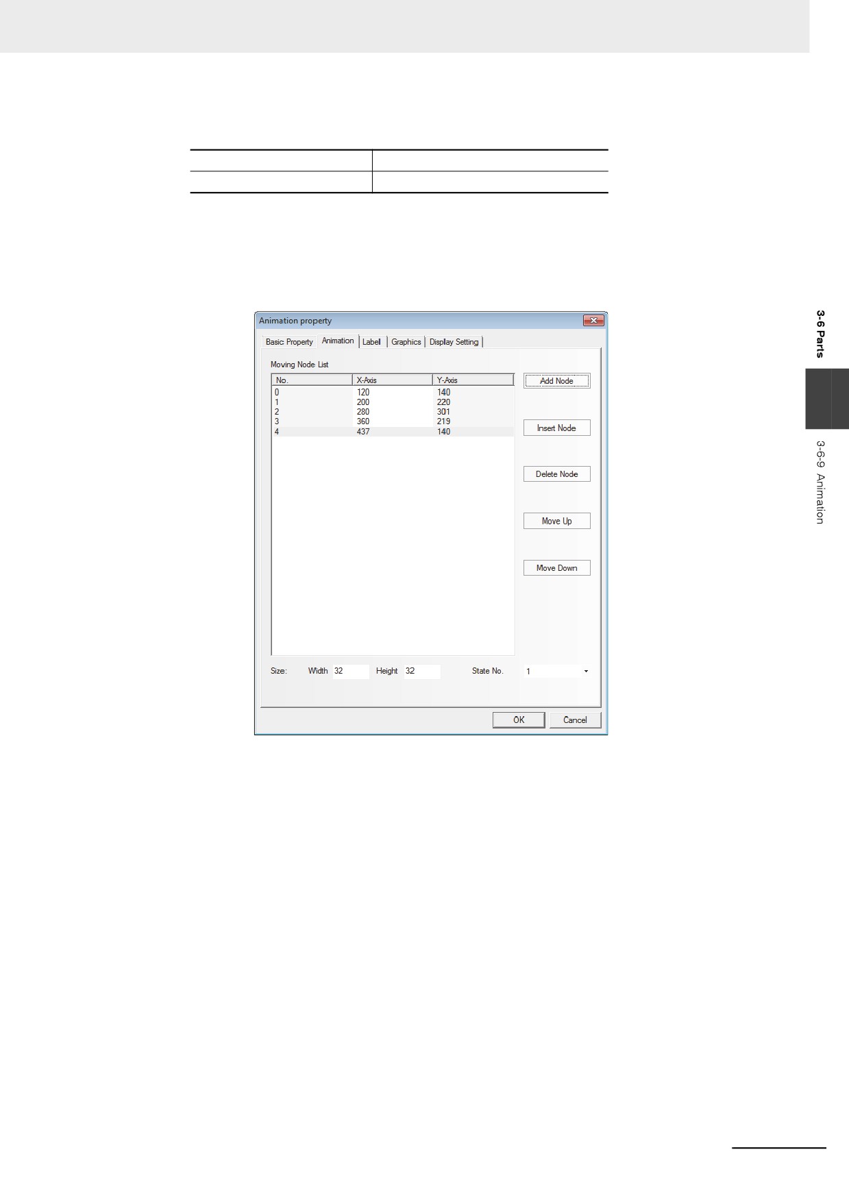
Switch to the [Animation] tab.
3
State No.: Selects the total states displayed by the Animation component. It determines the
number of states of the Vector Graphics or bitmap displayed in the preset path.
Add Node: Adds one moving node in the end of the preset path.
Insert Node: Inserts one moving node after the moving node pointed by the mouse.
Delete Node: Deletes one moving node.
Move Up: Moves the moving node pointed by the mouse into the place before the previous
node.
Move Down: Moves the moving node pointed by the mouse into the place after the next node.
Graphics Size (Width/Height): This is the size of Animation Components displayed on the
path. On all moving nodes, vector graphics or bitmap are
displayed in the state which was resized with the parameter
specified by this item.
Moving Node List: Displays all the numbers and coordinate values for all the track nodes, and
No.0 is for the 1st moving node, and No.1 is for the 2nd moving node, and
so on. The total number of the moving node is determined by the number
of moving node when you put the component in the PT at the beginning.
X(Y) represent the coordinate position corresponding to the moving node,
and you can reset the coordinate position for each moving node here.
3-117
3 Functions of NB-Designer
5
Switch to the [Label] tab and add the corresponding texts to be displayed.
6
Switch to the [Graphics] tab and select Vector Graphics or bitmap to move or display the state.
7
Press the [OK] button to complete the setup of the Animation component.
3-6-10
Number Input
The Number Input component can be used to display the current data contained in word
address inside a specified PT or of PLC, to input data through the pop-up keyboard and to change the
data contained in this address by pressing “ENTER” button.
z Process of adding one Number Input component
1
Press the Number Input component icon, drag it to the screen, then the [Basic Properties]
dialog box of the Number Input component will pop up.
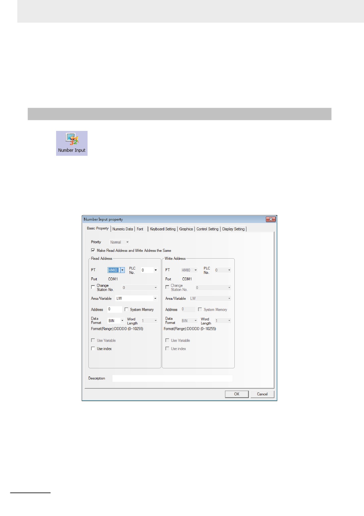
Read/Write Addresses: Refers to the specified word address read and written by the Number
Input component.
Address: Refers to the first address of the word address corresponding to the Number Input
component.
Word Length: Displays the data length of the address.
3-118
3 Functions of NB-Designer
2
Go to the [Numeric Data] tab.
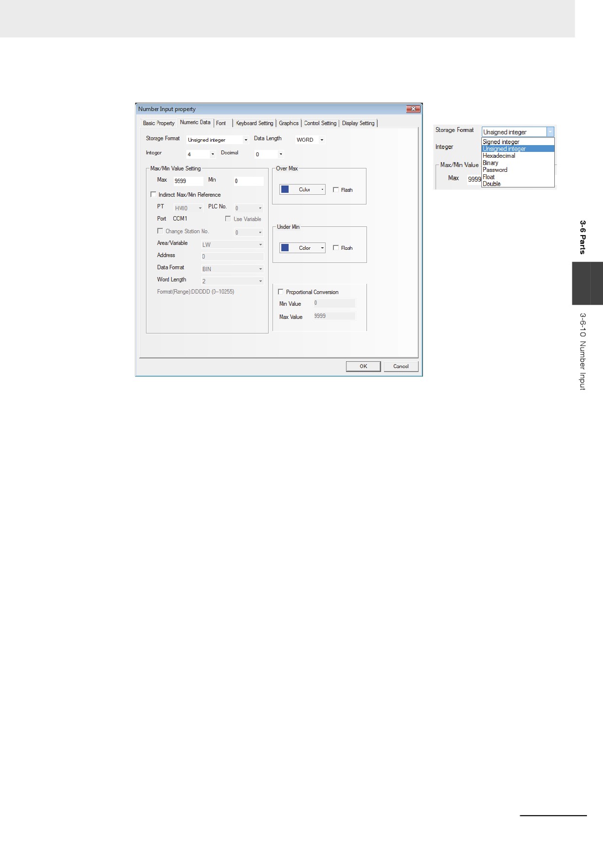
3
Data Format: Sets the data format corresponding to data contained in specified word address
and 7 types are available.
Max/Min Value Setting: Setting the range of input available value.
Over Max/Under Min: Specifying color of the value displayed when it exceeds the Max or the
Min of the value.
Flash: When the value of the specified word address is greater than the Max or less than the
Min, the value of the component will be flashed to make the transfinite alarm more
visible.
Proportional Conversion: The value of the specified word address will be converted
according to the settings and displayed on number input
component. To select this function, [Min Value] and [Max Value]
must be set.
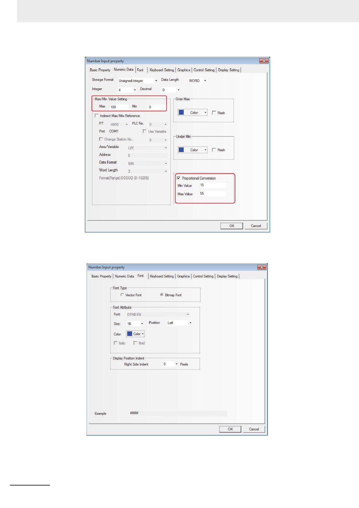
For example: it is assumed that the original data is represented by “A” and the displayed data
by “B”, then the data B can be obtained by the following conversion formula:
B = [Minimum Proportional Value] + (A - [Minimum Value of Original Data]) × Proportion
Where, Proportion = ([Maximum Proportional Value] - [Minimum Proportional Value]) /
([Maximum Value of Original Data] - [Minimum Value of Original Data])
Take the following graphics as example, when the original data is 20, then the value after
conversion is 15 + (20-0) × (55-15) / (100-0) = 23, so the value displayed in the component will
be 23.
3-119
3 Functions of NB-Designer
3
Switch to the [Font] tab and set the font size, color and alignment method, etc. for the displayed
value.
Font Size: Sets the size of the font.
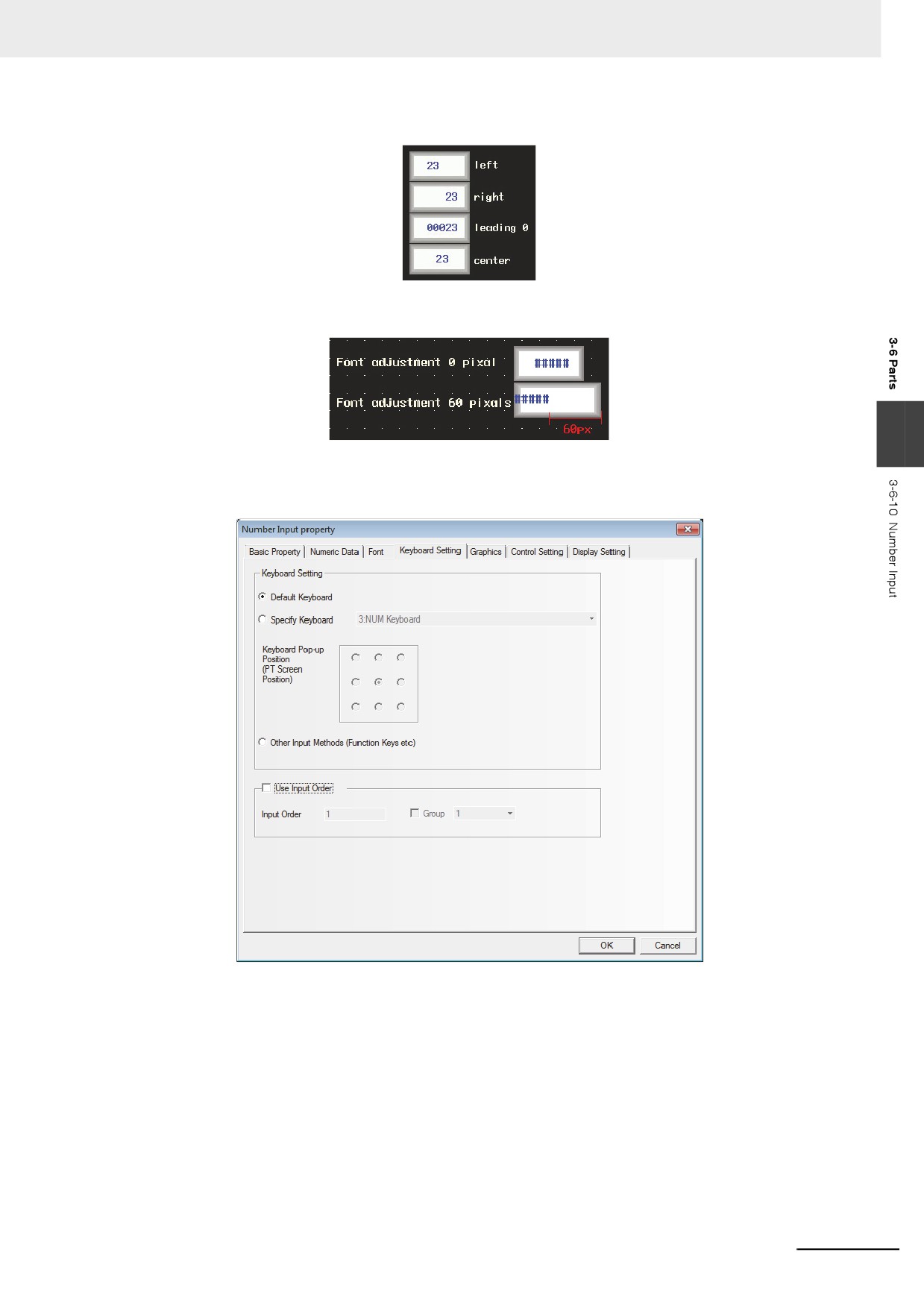
Position: Sets the displayed position of the value. For example, set “Integer”, “Decimal” and
the input value to “5”, “0” and “23” respectively, then the formats as shown below will
be displayed.
3-120
3 Functions of NB-Designer
Display Position Indent: Increases the width of the display area for the font rightward with the
unit of pixel point.
3
4
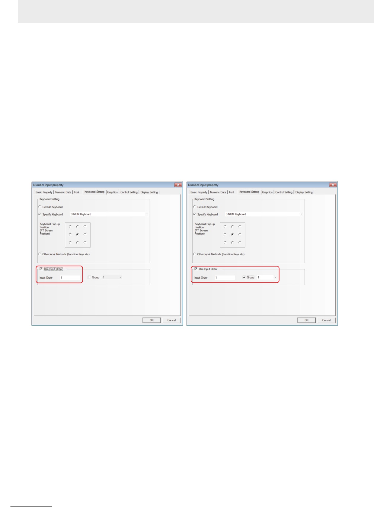
Switch to the [Keyboard Setting] tab and make Keyboard Setting for the pop-up keyboard type
and check Use Input Order.
Default Keyboard: Refers to the keyboard used by the Common Sheet, all of the Number
Input components will call the 3:NUM keyboard. The default setting of
Number Input is “Use [Default Keyboard]”.
Specified Keyboard: One specified keyboard will be called and only after checking in the
[Screen Attribute] check box of the [Screen Property] dialog box for the
page set by function keys and others and setting [Keyboard] for [Screen
Property], the keyboard can be displayed in the dropdown list of the
[Specify Keyboard].
Keyboard Pop-up Position: 9 positions can be adjusted.
Other Input Methods (Function Key etc): Using the function keys, the keyboard is specified
when entering numbers.
3-121
3 Functions of NB-Designer
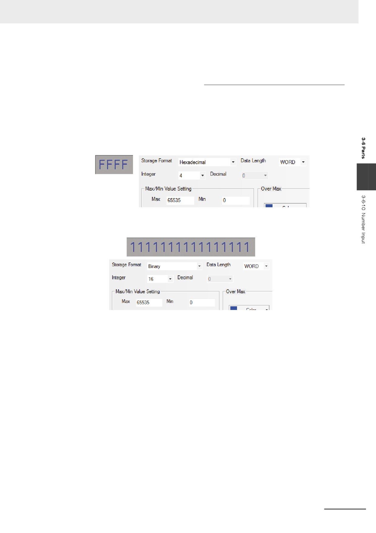
Use Input Order: In the order of number input of [Input Order] specified to number input, text
input, or Note book, numbers and text strings can be entered continuously.
Touching [Enter] during data entry allows to move the cursor among input
components in the order of the numbers of [Input Order] which were
specified by [Use Input Order] (Ascending order: 1-->2-->...-->last No.-->1--
>...) In this settings, the keyboard will not be closed automatically and will be
kept to be displayed on the screen until touching to [X] (closing component)
displayed on the keyboard.
Group is used to classify the multi-group of components needing consecutive inputs. The
components with the same group number belong to the same group, and the cursor will be
cyclic in the same group of components. When the “Enter” is pressed, the keyboard will not be
closed automatically, but will always be displayed in the screen until the close button “X” in the
keyboard is touched.
Setting of [Use Input Order]
Go to [Keyboard Setting] Property tabs for the Number Input component, Text Input
component and Note Book component respectively, and check the [Use Input Order].
5
Switch to the [Graphics] tab and select the Vector Graphics or bitmap representing the
touching area and touching state.
6
Switch to the [Control Setting] tab and make the Security Setting and set the Triggering action.
7
Press the [OK] button to complete the setup of the Number Input component.
Storage Format:
(1) Decimal System (signed int/unsigned int):
The data is displayed in decimal (0~9).
The data is displayed according to the instructions for the digits after the decimal point and
the data will be arranged from the digits after the decimal point. For example, the digits after
the decimal point is 2, then “14561” will be displayed as “145.61”. "-"(minus) is treated as an
Integer.
3-122
3 Functions of NB-Designer
Data after Proportional Conversion:
The value of the communication addresses set is converted proportionally before
displaying. The conversion formula is as follows.
Read
Minimum
Maximum Value after
Minimum Value after
(
-
)
×
(
-
)
Value after
Minimum Value after
Value
Input Value
Proportion Conversion
Proportion Conversion
=
+
Proportion Conversion
Proportion Conversion
(Maximum Input Value-Minimum Input Value)
The converted value will display the data according to “the digits before the decimal point”
and “the digits after the decimal point”. For example, the value to be converted is 123.456,
but “the digits after the decimal point” and “the digits before the decimal point” are “2” and
“3” respectively, so the converted value is displayed as “123.45” and the last digit is cut.
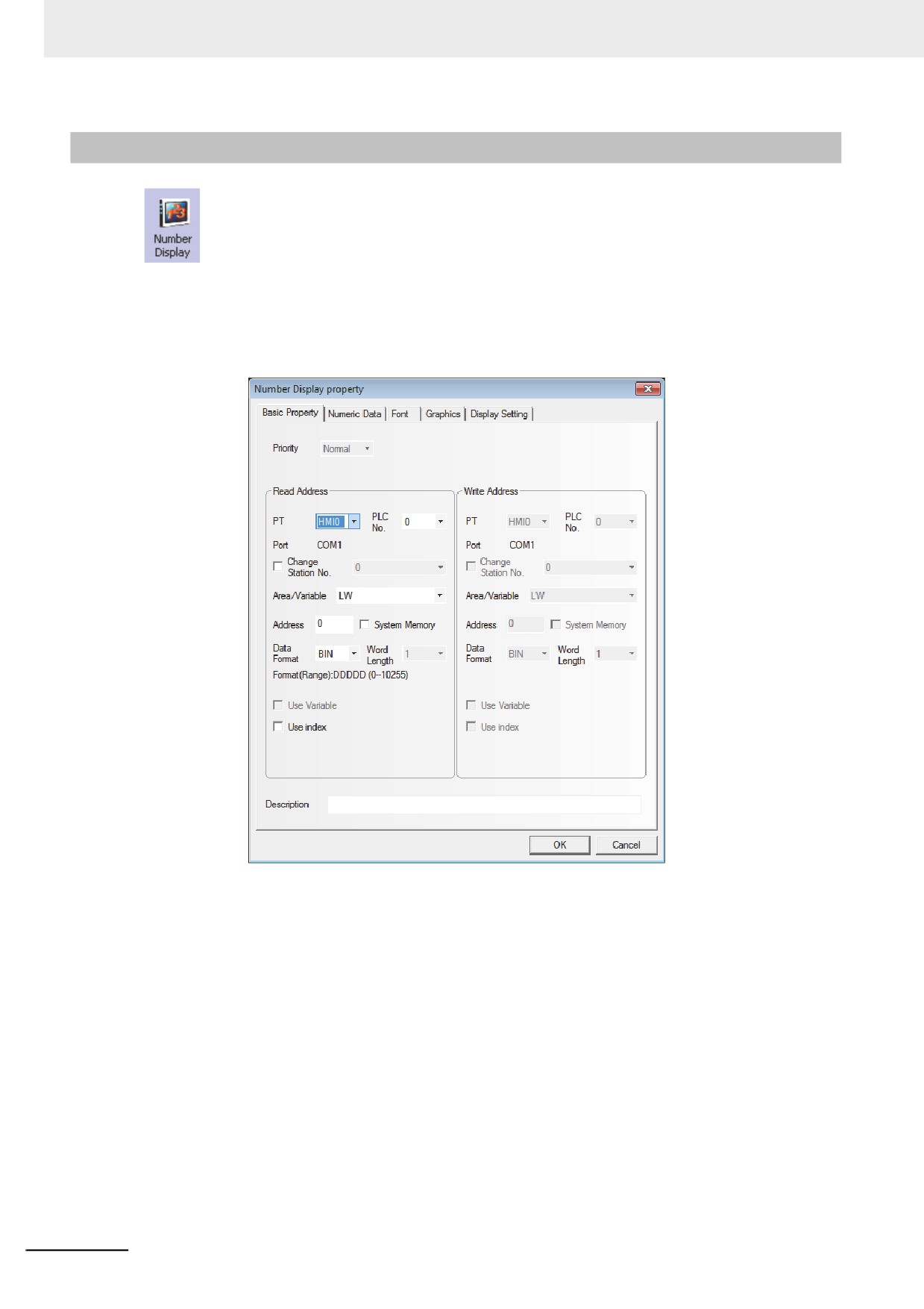
(2) Hexadecimal System (hex):
The data is displayed in hexadecimal format (0~F), and the conversion ratio and the
decimal point are eliminated.
3
(3) Binary System (bin):
The data is displayed in binary format (0 and 1), and the conversion ratio and the decimal
point are eliminated.
In the hexadecimal and binary formats, the input maximum value or minimum value are
treated as unsigned integer.
(4) Password (password):
Only “****” can be displayed and all the values to be read are hidden, and it is used to input
the password. Its conversion ratio and the decimal point are eliminated.
(5) Single-precision Floating-point Value (float):
The data in the controller will be converted into the decimal data from the data in 32-digit
IEEE floating format and will be displayed in decimal format.
(6) Double-precision Floating-point Value (double):
The data in the controller will be converted into the decimal data from the data in 64-digit
IEEE floating format and will be displayed in decimal format.
For details about the single-precision floating-point value and double-precision floating-
point value, refer to IEEE-754 Standard.
3-123
3 Functions of NB-Designer
3-6-11
Number Display
The Number Display component is used to display the data in the specified word memory.
z Process of adding one Number Display component
1
Press the Number Display component icon, drag it to the window, then the [Basic Properties]
dialog box of the Number Display component will pop up.
Read Address: Refers to the word address displayed by the Number Display component.
Address: Refers to the first address of the word address corresponding to the Number Display
component.
Word Length: Displays the data length of the read address.
3-124
3 Functions of NB-Designer
2
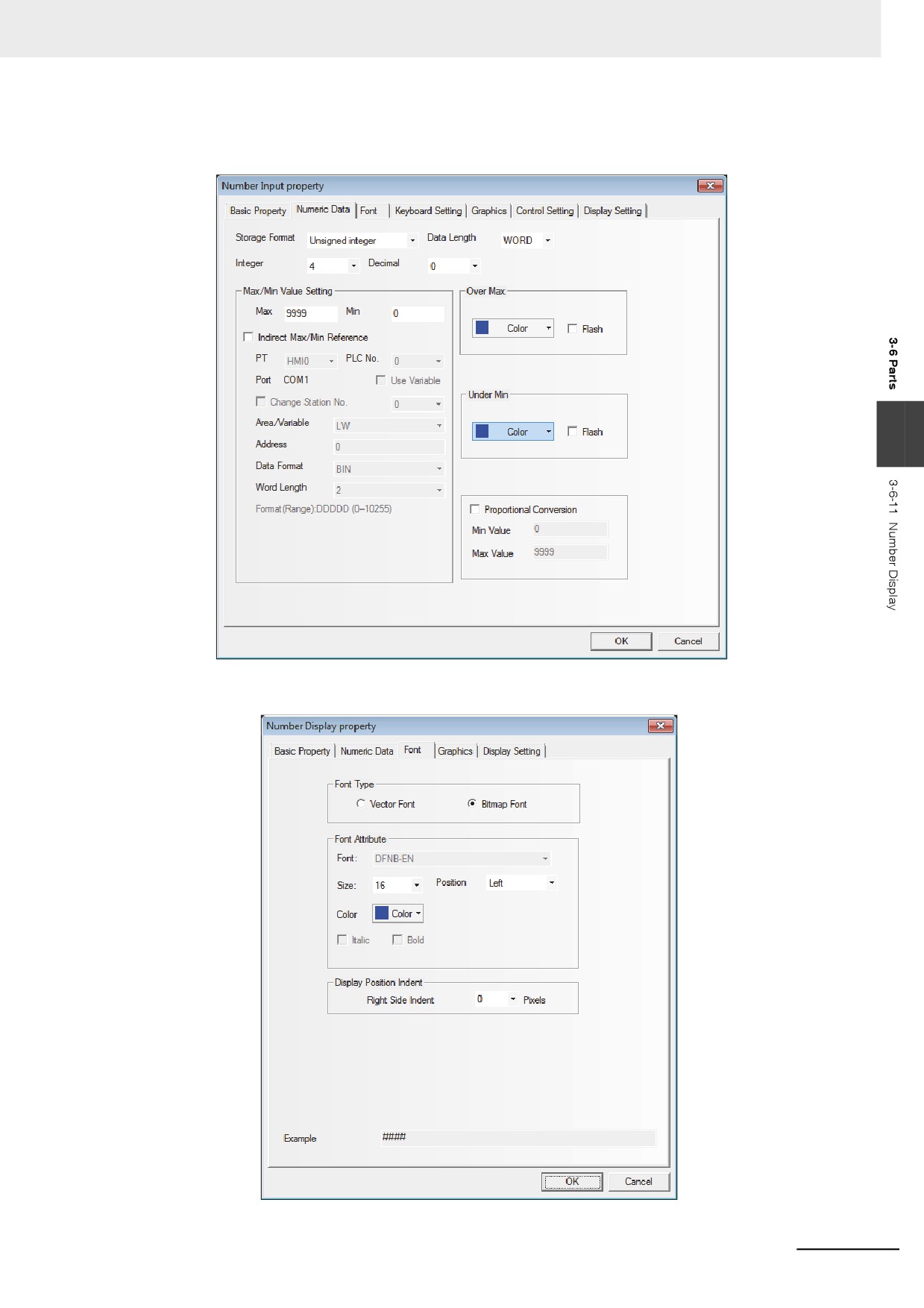
Refer to the relevant contents of the [Number Input] component, and fill in the contents in the
[Numeric Data] tab.
3
3
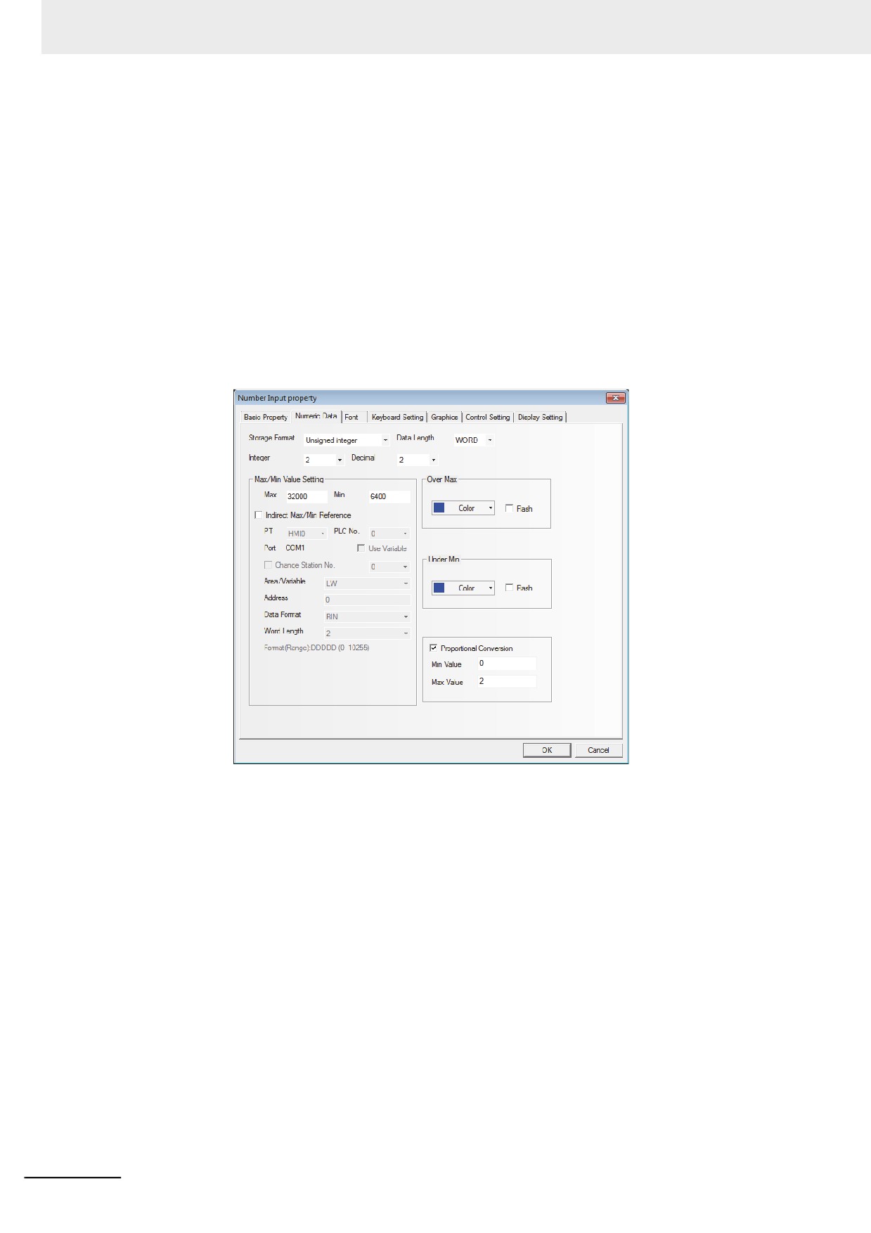
Switch to the [Font] tab and make related settings referring to the Number Input component.
3-125
3 Functions of NB-Designer
4
Press the [OK] button to complete the setup, and place the Number Display component in a
proper position.
z How to use the “Proportional Conversion” in the Numeric Data tab in Number
Display Component Property dialog box.
Quite a number of PLCs or other controllers don’t support decimals or negatives, and in many
cases, the actual values registered in PLCs or other controllers are different from the values the
users want to display on the PT, thus Proportional Conversion is required. For example, the actual
frequency of an inverter is 0~5000, while what is expected on the PT is 0~50 HZ, and in this case,
Proportional Conversion can be used.
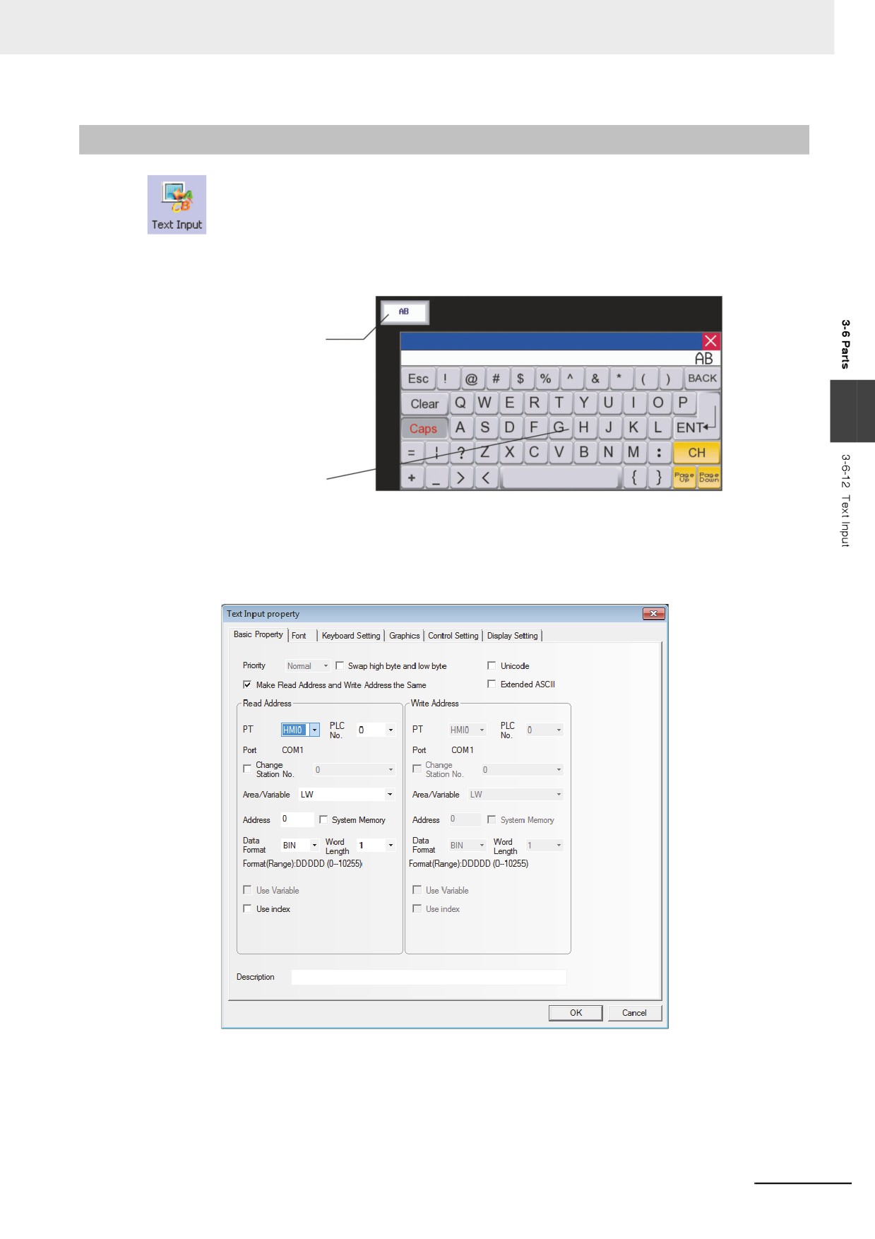
Another example: the range of values sampled from the PLC is 6400~32000, while the range
desired to be displayed on the PT is 0.00~2.00.
This can be realized with settings shown below:
3-126
3 Functions of NB-Designer
3-6-12
Text Input
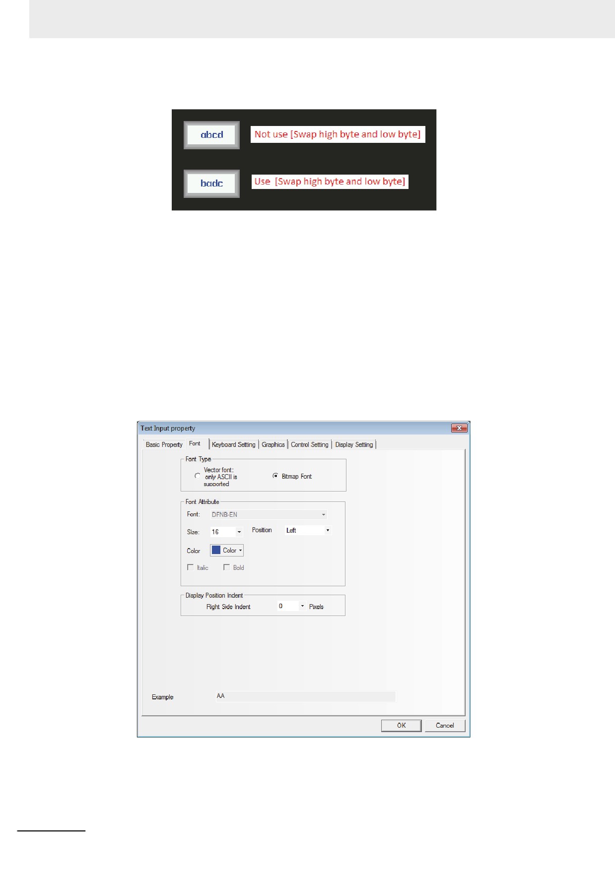
Text Input component can modify or display the data in the specified word memory, which is
analyzed through the standard ASCII character table as default settings. The input data is saved to a
consecutive memory with the “Registered Address” as the first address. Low-byte character codes are
displayed on the left, while high-byte character codes are displayed on the right.
Enable the touching area and enter
the input state
3
Input from the keyboard
z Process of adding one Text Input component
1
Press the Text Input component icon, drag it to the window, then the [Basic Properties] dialog
box of the Text Input component will pop up.
3-127
3 Functions of NB-Designer
Swap high byte and low byte: Refers to the interchange of the high-byte and the low-byte for the
same byte, as shown below.
Unicode: If you check the check box for this function, the specified data is dealt as Unicode.
Extended ASCII: Checking this option can display the extended ASCII characters between 0×80
and 0×ff in the ASCII codes. When it is checked, Chinese can’t be displayed in
the Text Input component, Text Display component and Note Book component.
Only one of [Unicode] or [ASCII] can be selected.
Read/Write Address: Refers to the word address (It contains up to 16 words, each of which
contains 2 ASCII characters) displayed and modified by Text Input
component in PLC.
Address: Refers to the first address of the word address corresponding to the Text Input
component.
Word Length: 1~16 are available for the Read/Write Address.
2
Switch to the [Font] tab and fill in the Properties of displayed data referring to that for the
Number Input component.
3-128
3 Functions of NB-Designer
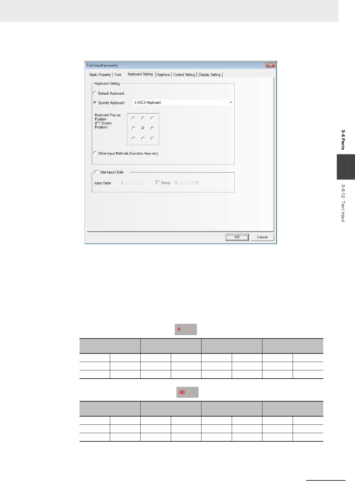
3
Switch to the [Keyboard Setting] tab and select the keyboard type.
3
4
Switch to [Graphics] tab and select the Vector Graphics or bitmap representing the touching
area and touching state.
5
Switch to the [Control Setting] tab and make the Security Setting and set the Triggering action.
6
Press the [OK] button to complete the setup of the Text Input component.
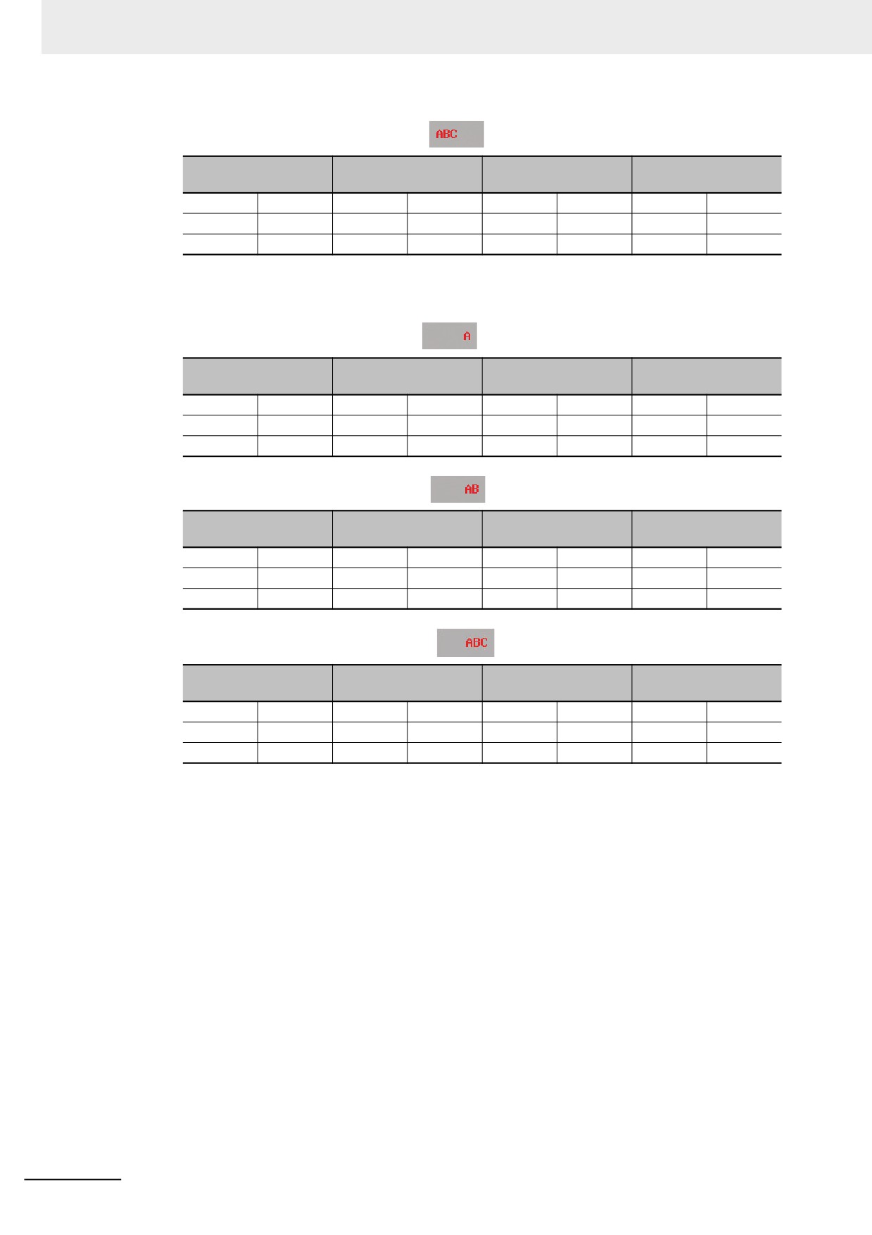
The storage method of the text input is explained as below.
(1) Select [Left] in [Alignment] of [Font Property]
When the character “A” is input
Lowest Word (Word
Highest Word
Word 2
Word 1
0)
High byte
Low byte
High byte
Low byte
High byte
Low byte
High byte
Low byte
20(H)
20(H)
20(H)
20(H)
20(H)
20(H)
20(H)
41(H)
A
When characters “AB” are input
Lowest Word (Word
Highest Word
Word 2
Word 1
0)
High byte
Low byte
High byte
Low byte
High byte
Low byte
High byte
Low byte
20(H)
20(H)
20(H)
20(H)
20(H)
20(H)
42(H)
41(H)
B
A
3-129
3 Functions of NB-Designer
When characters “ABC” are input
Lowest Word (Word
Highest Word
Word 2
Word 1
0)
High byte
Low byte
High byte
Low byte
High byte
Low byte
High byte
Low byte
20(H)
20(H)
20(H)
20(H)
20(H)
43(H)
42(H)
41(H)
C
B
A
(2) Select [Right] in [Alignment] of [Font Property]
When the character “A” is input
Lowest Word (Word
Highest Word
Word 2
Word 1
0)
High byte
Low byte
High byte
Low byte
High byte
Low byte
High byte
Low byte
41(H)
20(H)
20(H)
20(H)
20(H)
20(H)
20(H)
20(H)
A
When characters “AB” are input
Lowest Word (Word
Highest Word
Word 2
Word 1
0)
High byte
Low byte
High byte
Low byte
High byte
Low byte
High byte
Low byte
42(H)
41(H)
20(H)
20(H)
20(H)
20(H)
20(H)
20(H)
B
A
When characters “ABC” are input
Lowest Word (Word
Highest Word
Word 2
Word 1
0)
High byte
Low byte
High byte
Low byte
High byte
Low byte
High byte
Low byte
43(H)
42(H)
41(H)
20(H)
20(H)
20(H)
20(H)
20(H)
C
B
A
3-130
3 Functions of NB-Designer
3-6-13
Text Display
The Text Display component can display data in the specified word memory, which is
analyzed through the standard ASCII character table in default settings. Low-byte character codes are
displayed on the left, while high-byte character codes are displayed on the right.
z Process of adding one Text Display component
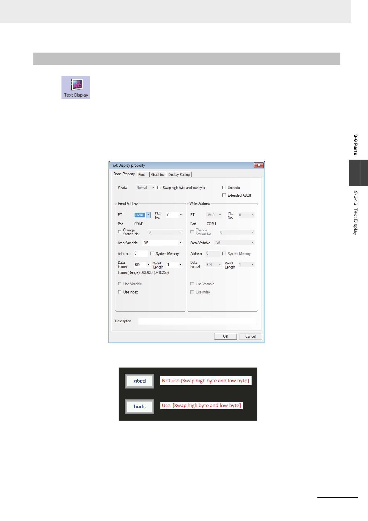
1
Press the Text Display component icon, drag it to the window, then the [Basic Properties]
dialog box of the Text Display component will pop up.
3
Swap high byte and low byte: Refers to the interchange of the high byte and the low byte for
the same byte, as shown below.
Unicode: If you check the check box for this function, the specified data is dealt as Unicode.
Extended ASCII: Checking this option can display the extended ASCII characters between
0×80 and 0×ff in the ASCII codes. When it is checked, Chinese can’t be
displayed in the Text Input component, Text Display component and Note
Book component. Only one of [Unicode] or [ASCII] can be selected.
Read Address: Refers to word address memory of PLC to be displayed (It contains up to 16
words, each of which contains 2 ASCII codes).
3-131
3 Functions of NB-Designer
Address: Refers to the first address of the word address corresponding to the Text Display
component.
Word Length: Displays the data length of the read address with 1 to 16 available.
2
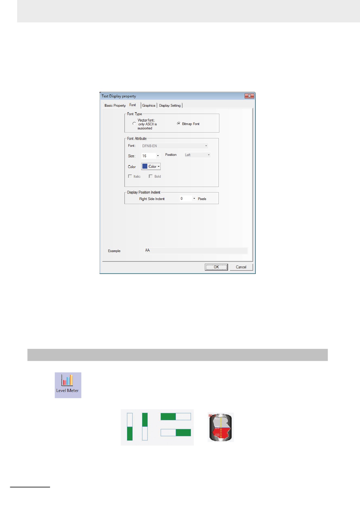
Switch to the [Font] tab and set the font size, alignment and color of the text to be displayed.
3
Switch to the [Graphics] tab and select the Vector Graphics or bitmap representing the
touching area and touching state.
4
Switch to the [Control Setting] tab and make the Security Setting and set the Triggering action.
5
Press the [OK] button to complete the setup of the Text Display component.
3-6-14
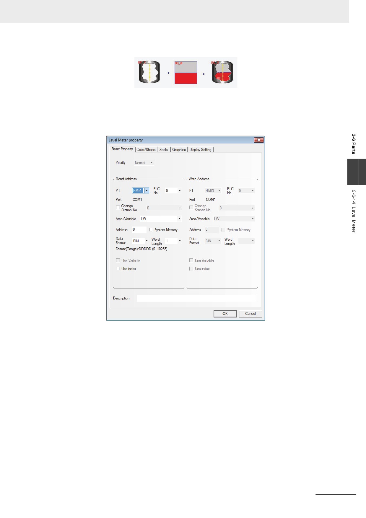
Level Meter
The value specified of the communication address is displayed in level picture based on the
upper limit value and the lower limit value set by [Level Meter Property].
3-132
3 Functions of NB-Designer
As shown as below, the user can customize Level Meter with any desired shape.
z Process of adding one Level Meter component
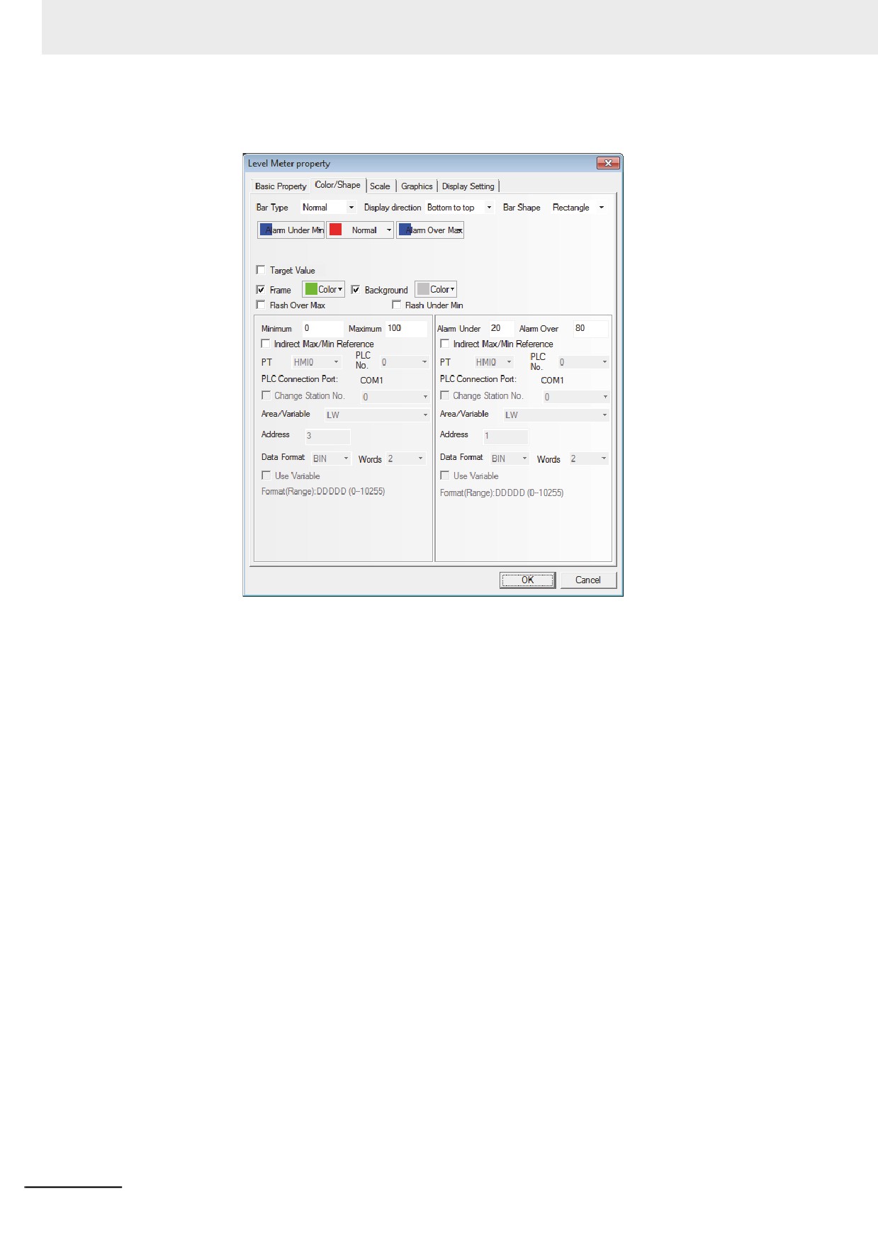
1
Press the Level Meter component icon, drag it to the window, then the [Basic Properties] dialog
box of the Level Meter component will pop up.
3
Read Address: Refers to the first address of the word address corresponding to the Level
Meter component.
Word Length: Displays the data length of the read address, supporting sing-word and double-
word.
3-133
3 Functions of NB-Designer
2
Switch to the [Color/Shape] tab and make settings as shown below.
3-134
3 Functions of NB-Designer
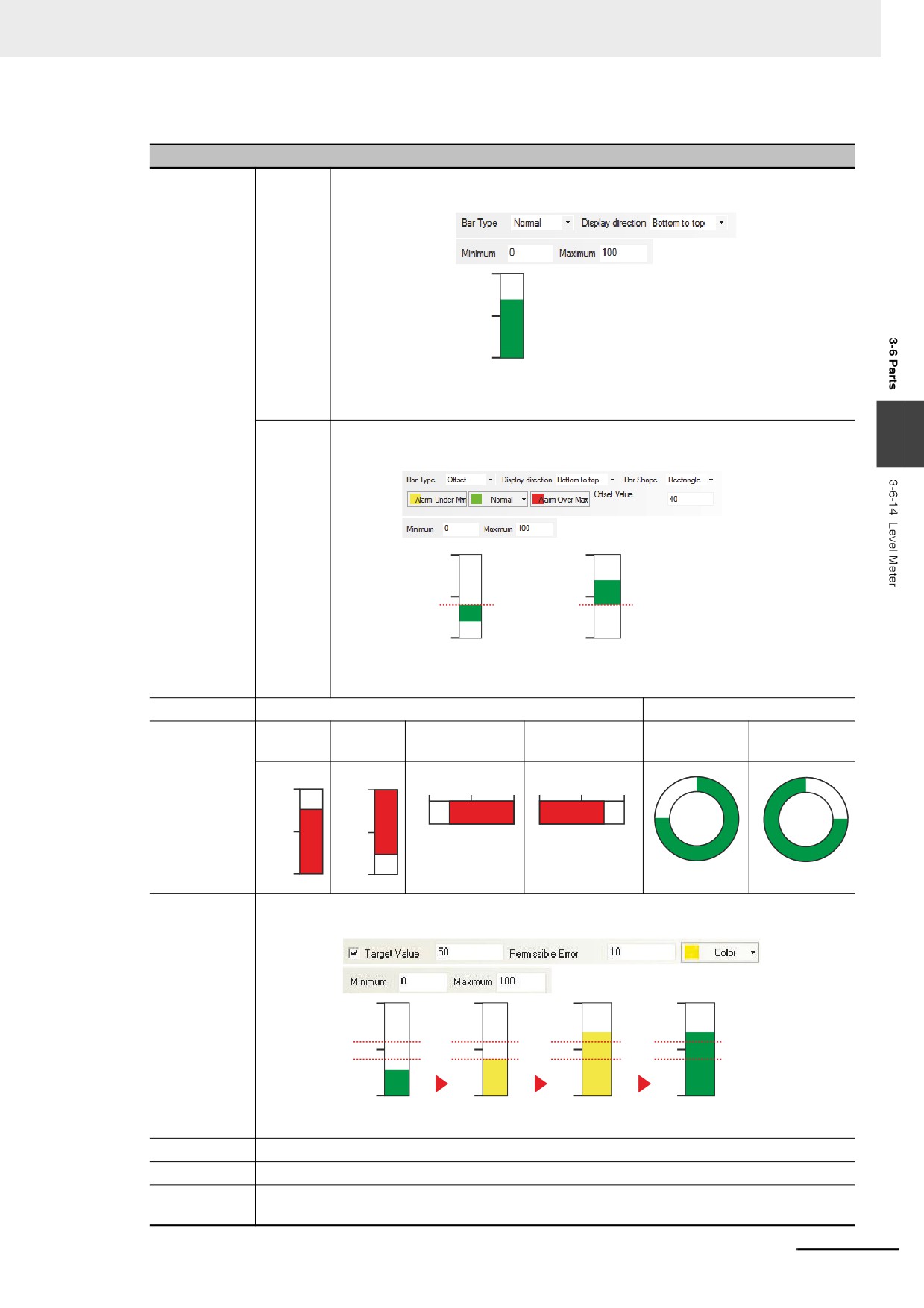
Detailed descriptions of the Level Meter Properties
Bar Type
Normal
Indicates the percentage relationship between the actual value and the set range
by means of a Level Meter.
100
50
0
D100=70
Offset
Displaying the value over the [Offset] for the actual value by means of a Level Meter.
3
Example: Maximum 100, Minimum 0, Offset Value 40
100
100
50
50
40
40
0
0
D100=20
D100=70
Bar Shape
Rectangle
Circle
Display
Bottom to
Top to
Right to left
Left to Right
Clockwise
Counterclockwise
direction
Top
Bottom
100
0
100
50
0
0
50
100
50
50
0
100
Target Value
When the value of the specified memory falls to the range [target value [allowable] gap]) specified
to the [Allowable gap], the fill area of the Level Meter will be displayed in the specified color.
100
100
100
100
60
60
60
60
50
50
50
50
40
40
40
40
0
0
0
0
D100=30
D100=40
D100=60
D100=70
Meter Width
When the Level Meter is of a Circle shape, the width of the fan can be set with the unit of pixel point.
Start Angle
When the Level Meter is of a Circle shape, the Start Angle of the fan can be set.
End Angle
When the Level Meter is of a sector shape, the End Angle of the sector ring can be set. If the
start angle is different from the end angle, shape of the meter will be fan-shaped.
3-135
3 Functions of NB-Designer
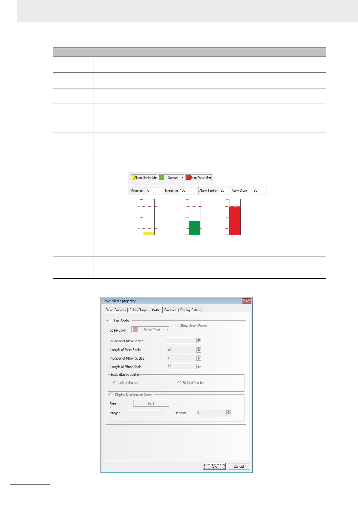
Detailed descriptions of the Level Meter Properties
Color
This option is used to set the colors for the normal state, warning the upper or lower limit value,
border and background of the Level Meter.
Flash Over
When the value of the specified memory exceeds the set Alarm Upper, the filled area of the
Max
Level Meter flashes.
Flash Under
When the value of the specified memory falls below the set Alarm Lower, the filled area of the
Min
Level Meter flashes.
Minimum/
Sets the upper and lower limit values of the display area for the Level Meter. The percentage of
Maximum
filled area in the Level Meter can be derived from the following formula: Percentage of filled
area in the Level Meter = (Value read by the memory - [Minimum value])/([Maximum value] -
[Minimum value]) ×100%
Indirect
Sets the upper, lower limit values and offset value of the Level Meter display area to be read
Max/Min
from the specified memories.
Reference
Alarm Upper/
Sets the range of the alarm area. When the value of the specified memory falls below the Alarm
Alarm Lower
Lower or exceeds the Alarm Upper, the filled area will be displayed in the specified color.
100
100
100
80
80
80
50
50
50
20
20
20
0
0
0
D100=10
D100=40
D100=80
Indirect Alarm
Sets the upper and lower limit values of the alarm area in the Level Meter display area to be
Over/Alarm
read from the specified memories.
Upper Reference
3
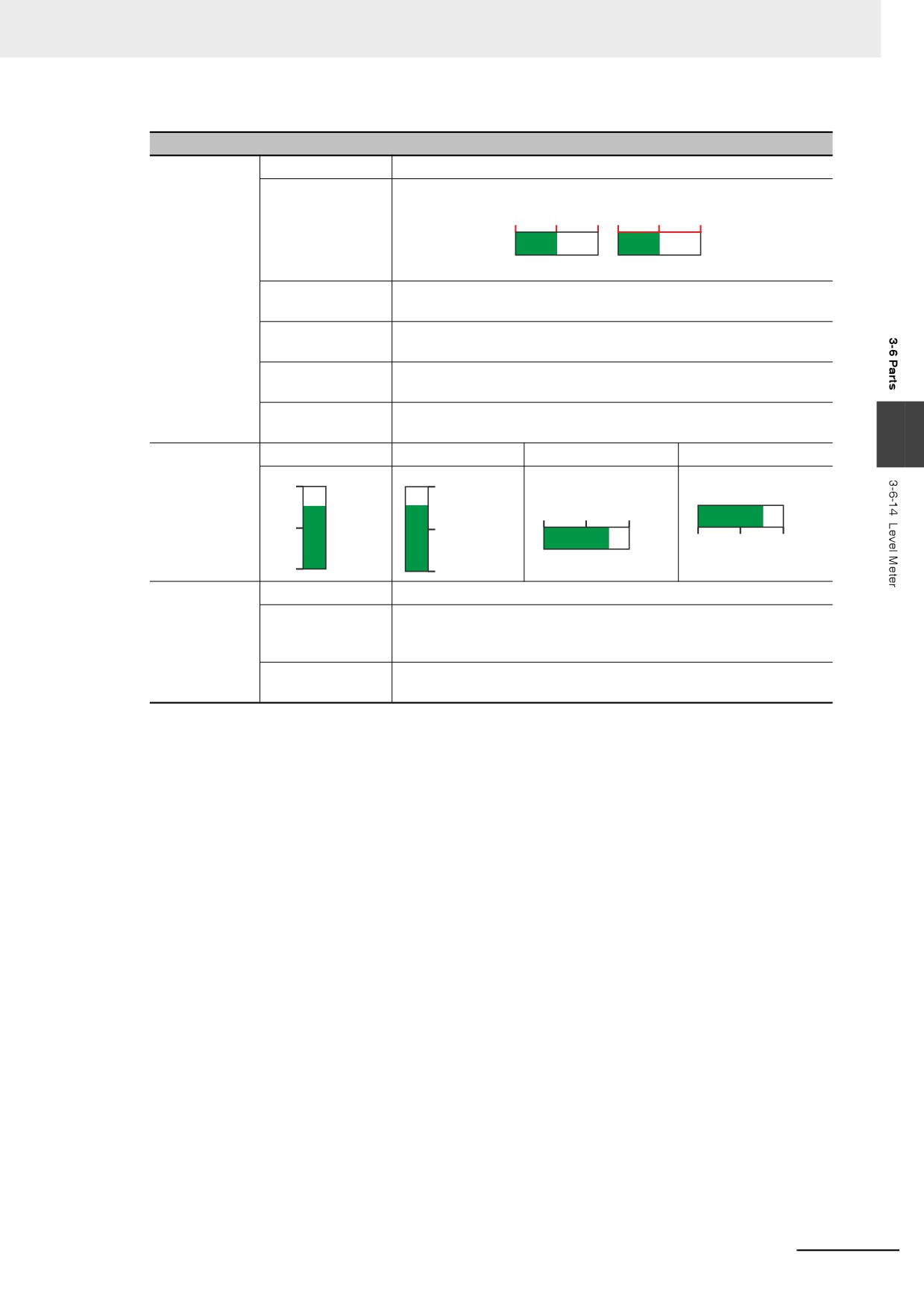
Switch to the [Scale] tab and make settings as shown below.
3-136
3 Functions of NB-Designer
Scale Properties
Use Scale
Scale Color
Sets the scale color of the Level Meter.
Show Scale Frame
Determines whether to show the scale frame.
0
50
100 0
50
100
Disable
Enable
Number of Main
Sets the main scale number to be displayed.
Scales
Length of Main
Sets the length of the main scale with the unit of pixel point.
Scale
Number of Minor
Sets the minor scale number to be displayed.
Scales
Length of Minor
Sets the length of the minor scale with the unit of pixel point.
Scale
3
Scale display
Left of the bar
Right of the bar
Top of the bar
Bottom of the bar
position
100
100
0
50
100
50
50
0
50
100
0
0
Display
Font
Sets scale font Properties.
Number on
Integer
Refers to the integer places displayed by the scale, which can’t be
Scale
changed by the user himself and is decided by the number of digits
specified by the decimal.
Decimal
Refers to the decimal places displayed by the scale, which can be
changed by the user himself.
Note When the Level Meter is of a Circle shape, scale display is not supported.
3-137
3 Functions of NB-Designer
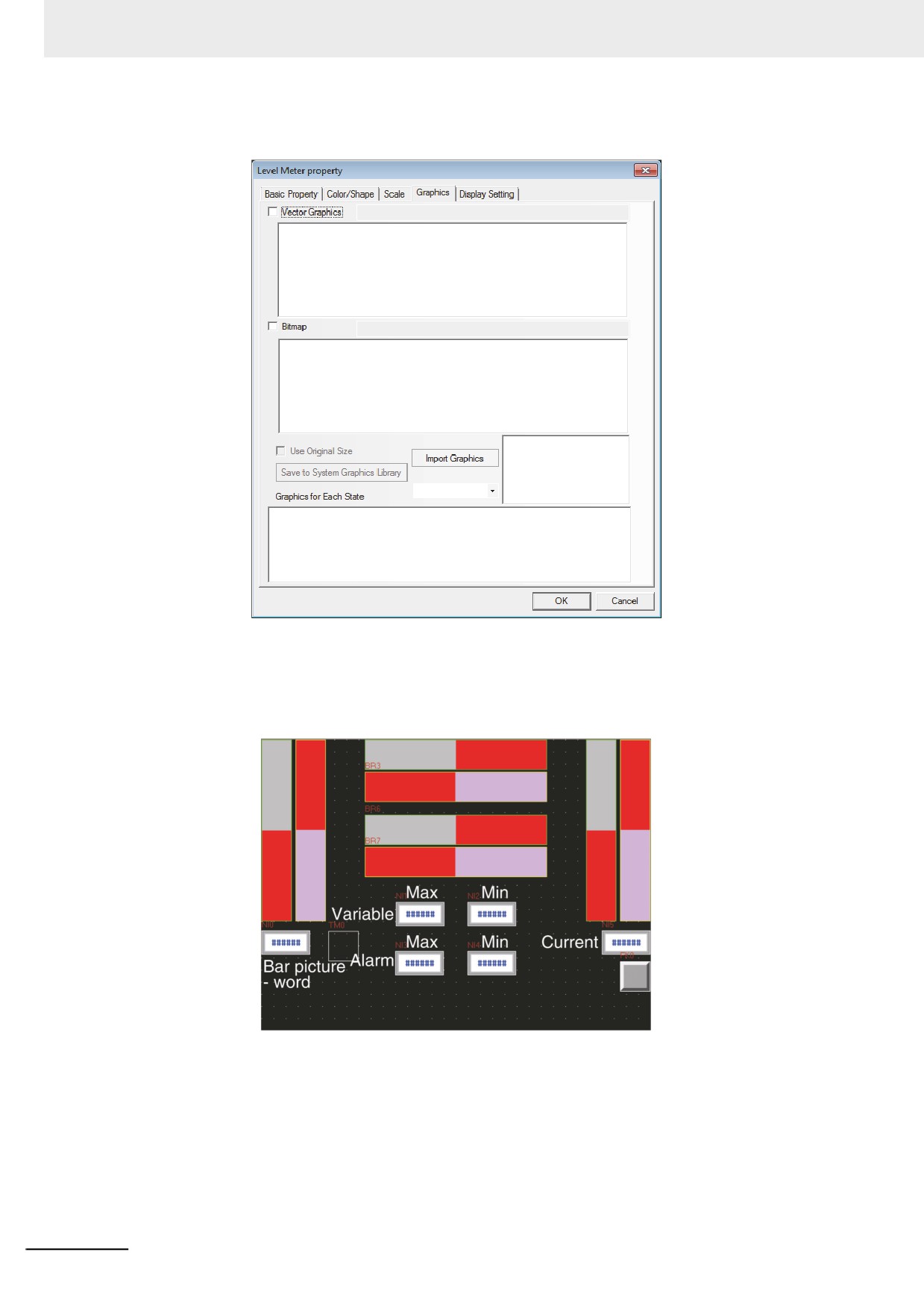
4
Switch to the [Graphics] tab and make settings as shown below.
Select proper graphics for the Bar Picture to improve the display effect.
5
Press the [OK] button to complete the setup of the Level Meter component.
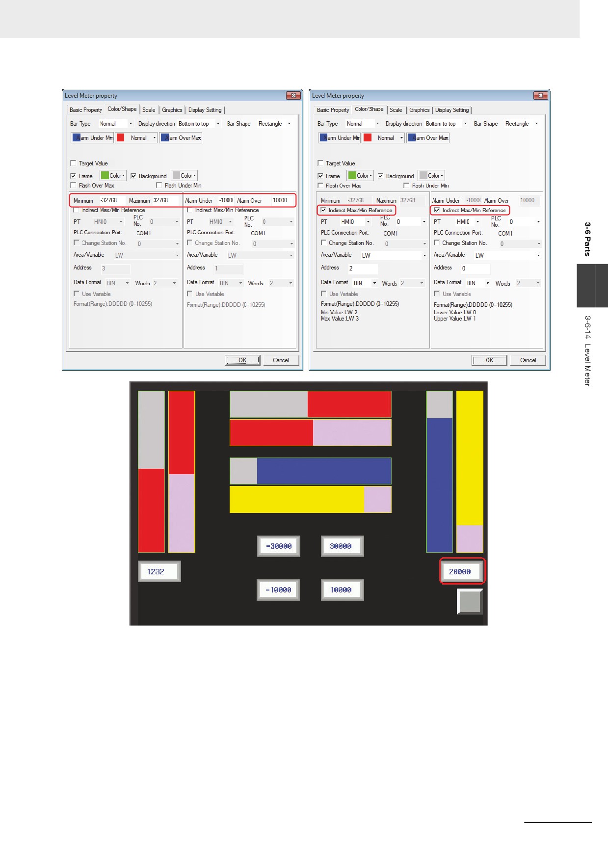
• Level Meter - Word
3-138
3 Functions of NB-Designer
3
Max
Min
Variable
Max
Min
Current
Alarm
Bar picture
- word
3-139
3 Functions of NB-Designer
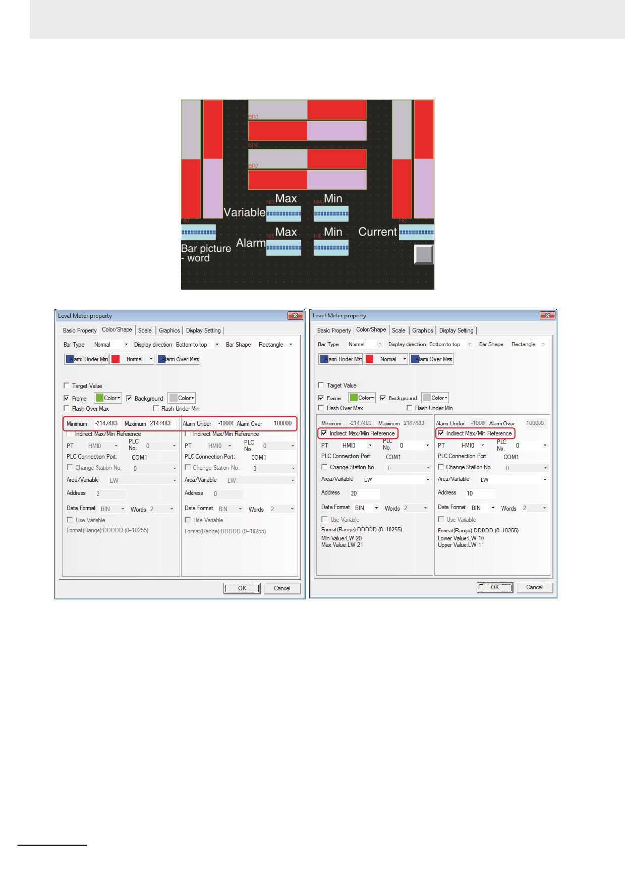
• Level Meter - Double-word
3-140
3 Functions of NB-Designer
3
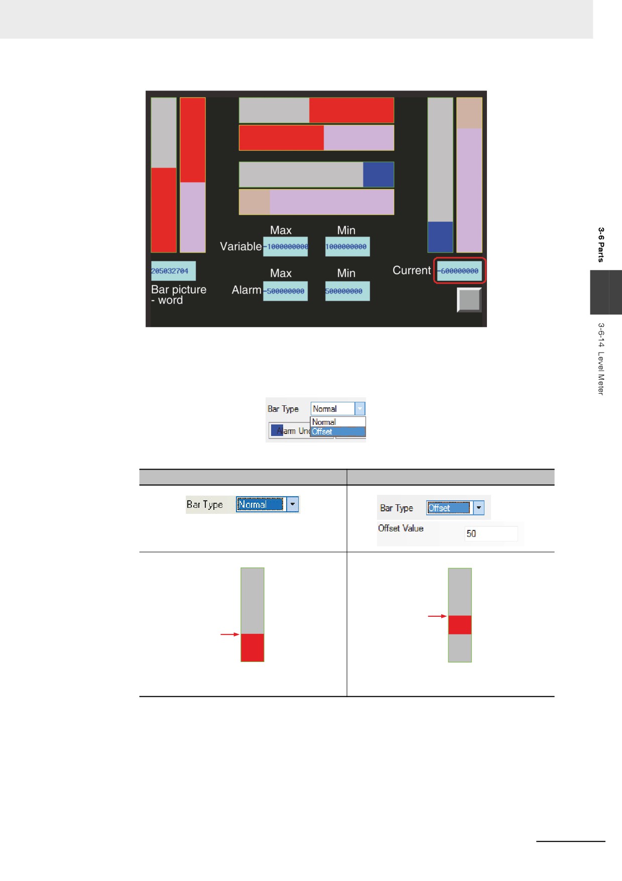
• Normal and Offset
When the [Offset] is selected, only the greater part of the values set by the offset value. For
example, setting “50” to [Offset value] and storing “60” in the communications address, only the
area corresponding to 50 to 60 of level meter will be filled.
Comparison of display effects between Normal and Offset:
Normal
Offset
Indicating the range from the current value to
Indicating the range from the current value to
lower limit value.
the [Offset].
3-141
3 Functions of NB-Designer
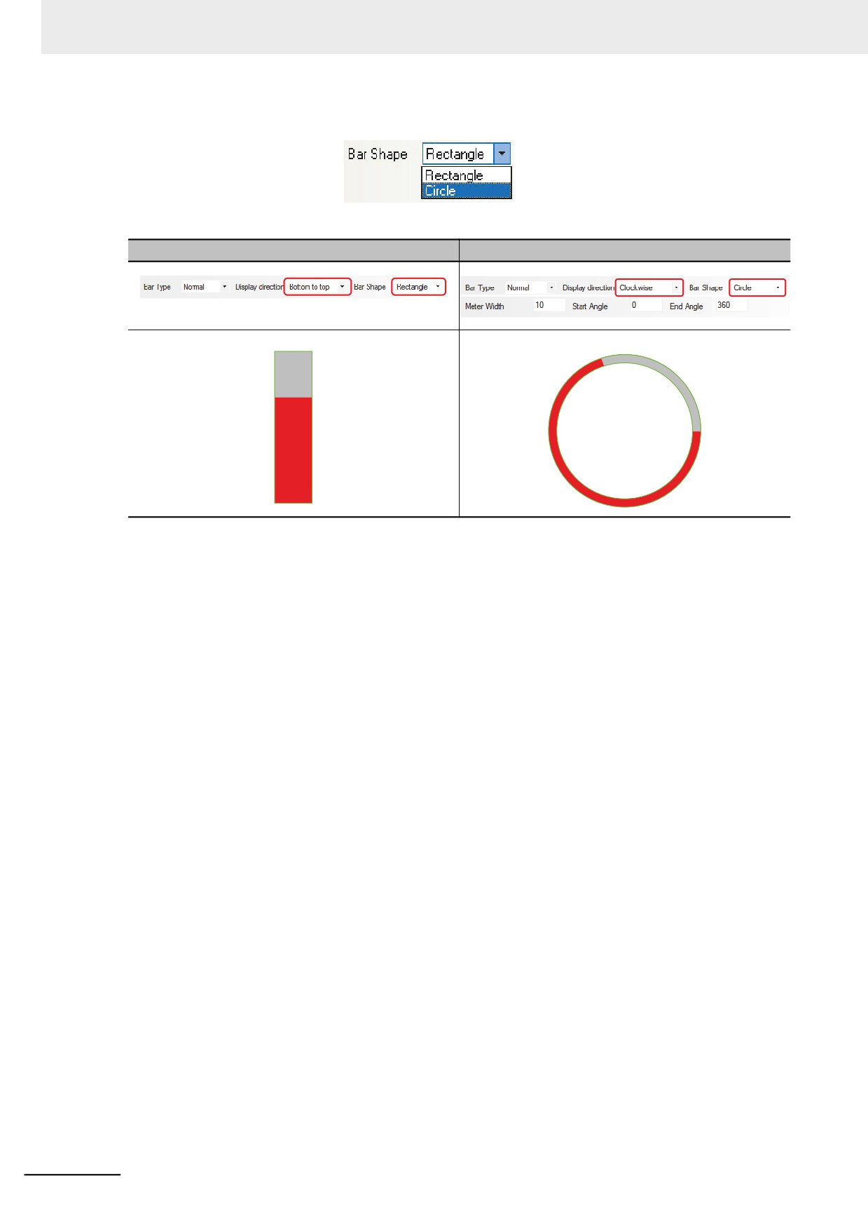
• Rectangle and Circle
Comparison of display effects between the Rectangle and Circle.
Rectangle
Circle
3-142