OMRON NB-Designer OPERATION MANUAL (NB-series, 2020) - page 5
3 Functions of NB-Designer
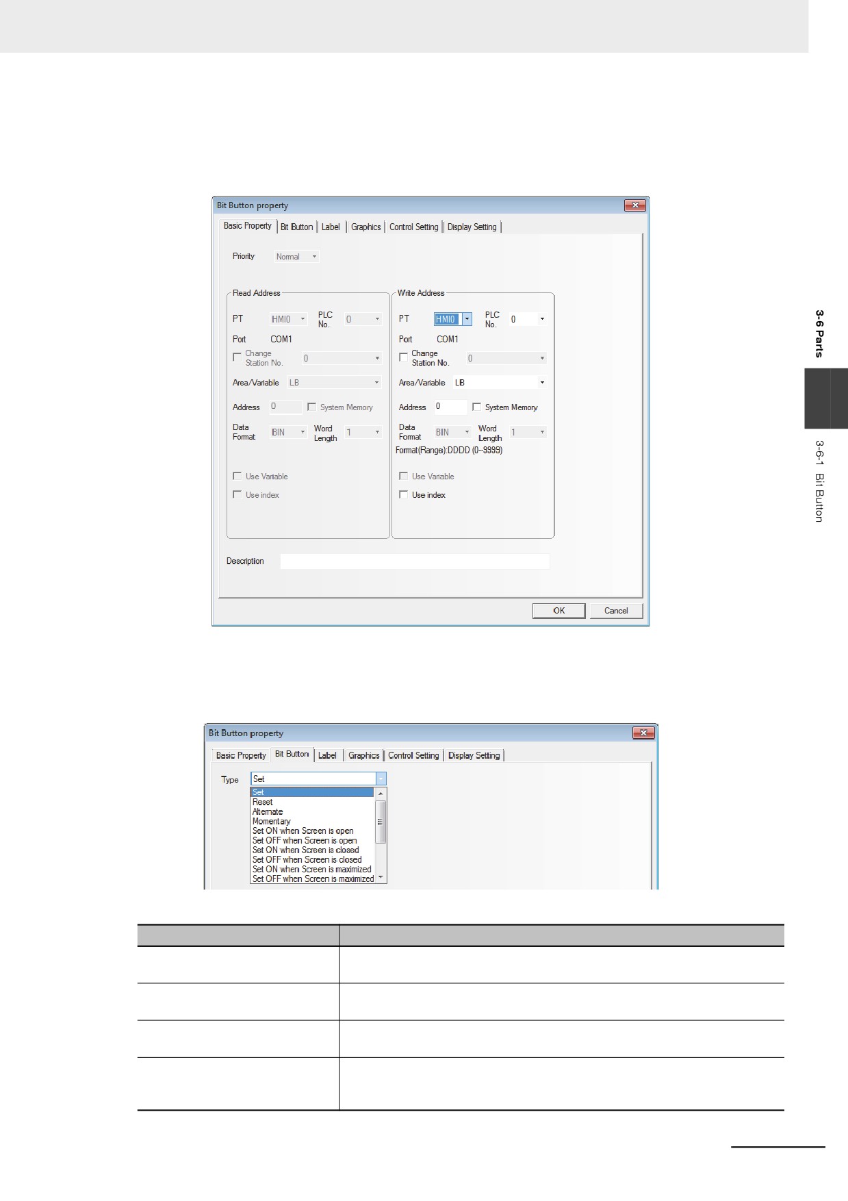
z Process of adding one Bit Button component
1
Drag the Bit Button component after it is pressed will make the [Basic Properties] of Bit Button
component pop up.
3
Write Address:Refers to the bit address corresponding to “On” or “Off” state controlled by the
Bit Button component.
2
Switch to the [Bit Button] tab.
Types and Functions of Bit Button Component
Type
Descriptions
Set
The specified bit address will turn On when the Bit Button component is
pressed. This state will continue even if the button is released.
Reset
The specified bit address will turn Off when the Bit Button component is
pressed. This state will continue even if the button is released.
Alternate
The specified bit address will change once (On˘ Off, Off˘ On) (Switched
back and forth) when the Bit Button component is pressed each time.
Momentary
The specified bit address will turn On only when the Bit Button component is
being pressed. Similarly, the bit address will turn Off when the component is
released.
3-83
3 Functions of NB-Designer
Type
Descriptions
Set On when Screen Open
The specified bit address will turn On when the screen containing the Bit
Button component is opened.
Set Off when Screen Open
The specified bit address will turn Off when the screen containing the Bit
Button component is opened.
Set On when Screen Close
The specified bit address will turn On when the screen containing the Bit
Button component is closed.
Set Off when Screen Close
The specified bit address will turn Off when the screen containing the Bit
Button component is closed.
Set On when Screen Maximized
The specified bit address will turn On when the screen containing the Bit
Button component is maximized.
Set Off when Screen Maximized
The specified bit address will turn Off when the screen containing the Bit
Button component is maximized.
Set On when Screen Minimized
The specified bit address will turn On when the screen containing the Bit
Button component is minimized.
Set Off when Screen Minimized
The specified bit address will turn Off when the screen containing the Bit
Button component is minimized.
Set On when Backlight Off
The specified bit address will turn On when the screen containing the Bit
Button component is displayed in the screen and the backlight is Off.
Set Off when Backlight Off
The specified bit address will turn Off when the screen containing the Bit
Button component is displayed in the screen and the backlight is Off.
Set On when Input Success
The specified bit address will turn On when the input using one Number Input
component in the screen containing the Bit Button component is successful.
Set Off when Input Success
The specified bit address will turn Off when the input using one Number Input
component in the screen containing the Bit Button component is successful.
3
Switch to the [Label] and add the text corresponding to the state.
4
Switch to [Graphics] tab and select the Vector Graphics or bitmap representing the touching
area and touching state.
5
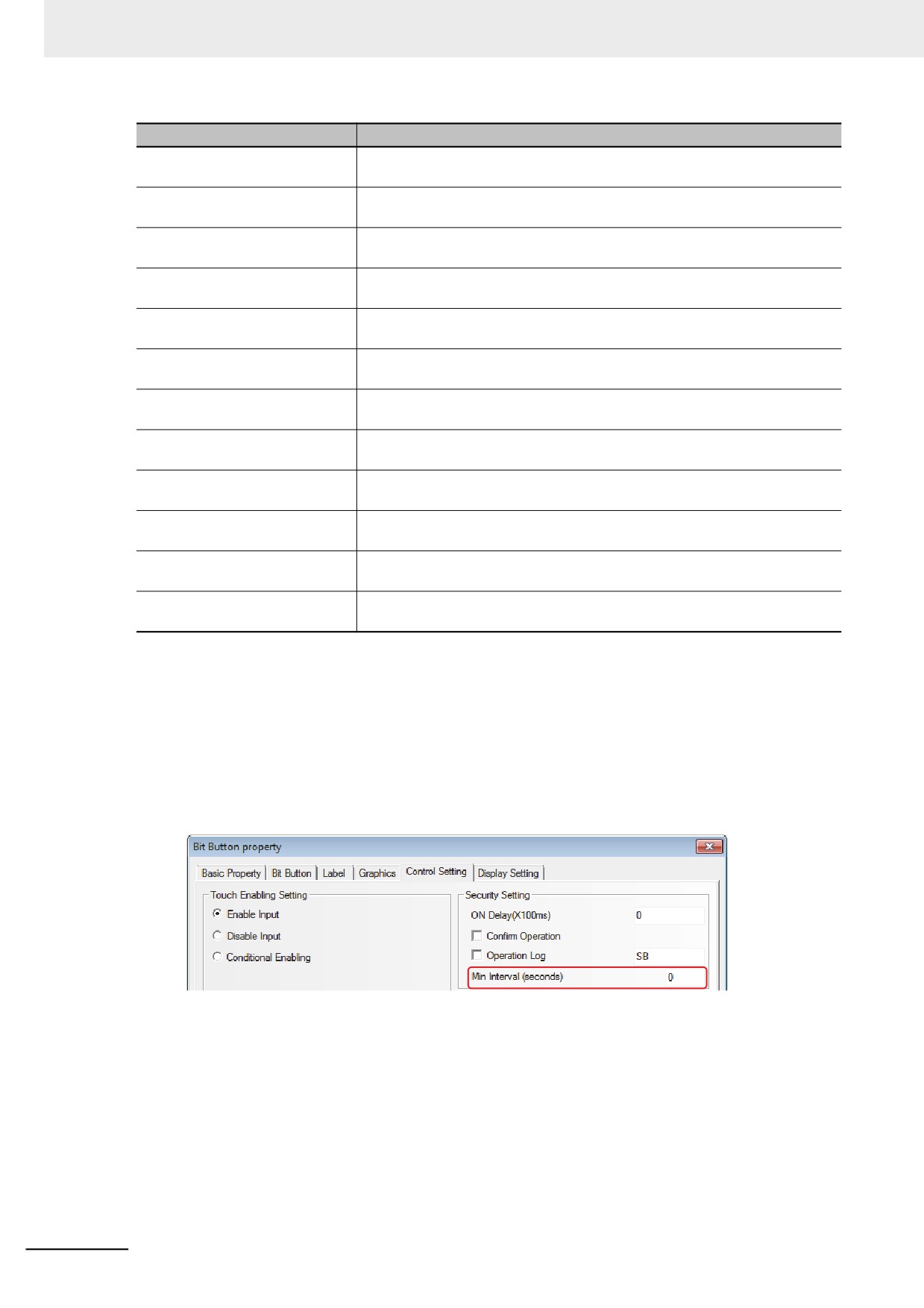
Switch to the [Control Setting] tab and make the Security Setting and set the Triggering action.
Min Interval (seconds): Refers to the interval between 2 valid touching operations for the same
component, and the default is 0 s.
6
Switch to the [Display Setting] tab and adjust the position and size for the Bit Button
component.
7
Press the [OK] button to complete the setup of Bit Button component.
3-84
3 Functions of NB-Designer
3-6-2
Bit Lamp
Bit Lamp displays the On/Off state of bit address inside a specified PT or of PLC device. If the
state is 0, the graphics with state of 0 will be displayed; If the state is 1, the graphics with state of 1 will
be displayed. If “Transport Font” is checked, the Label values corresponding to the different states can
be set and displayed.
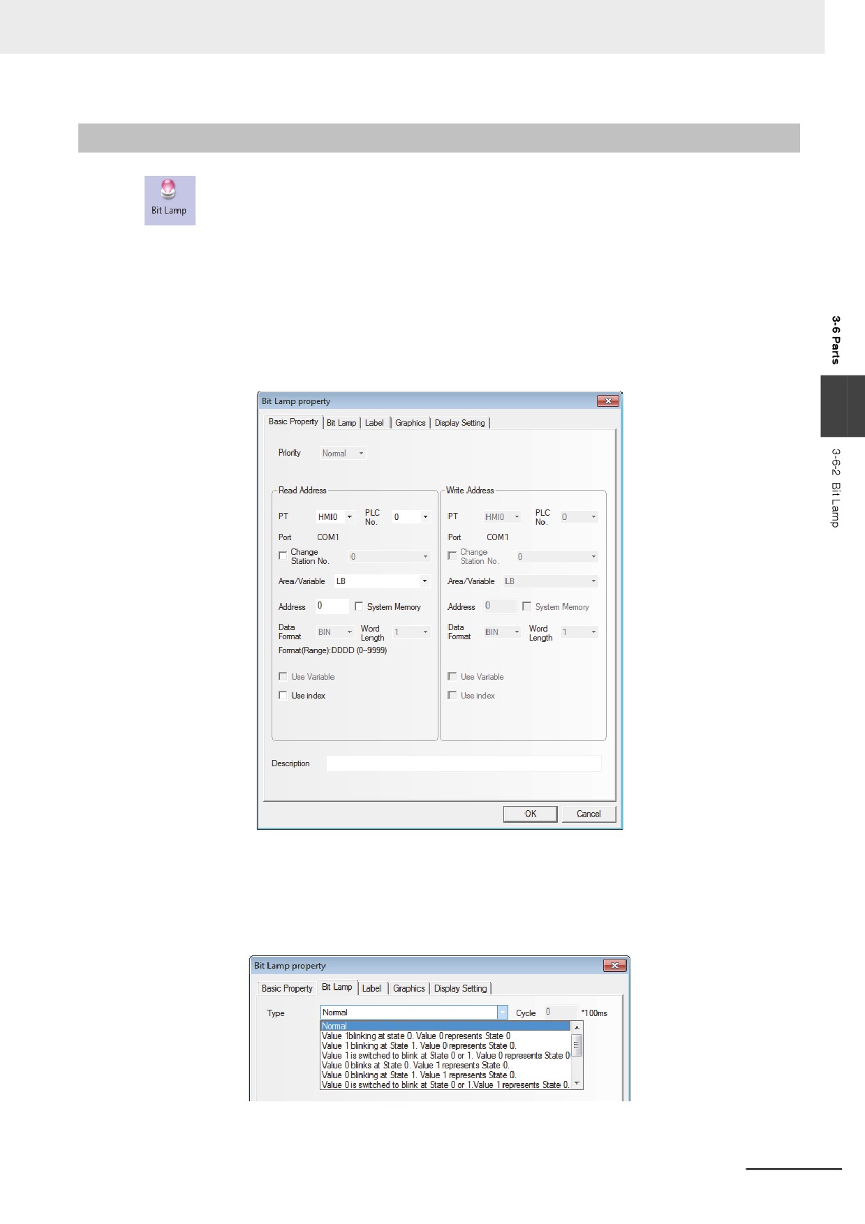
z Process of adding one Bit Lamp
1
Drag the Bit Lamp icon after it is pressed, then the [Basic Properties] dialog box for Bit Lamp
component will pop up.
3
Read Address: Refers to the bit address controlling the displayed information (such as the state,
graphics, label and so on) of the lamp.
Address: Refers to the bit address corresponding to the lamp.
2
Switch to the [Bit Lamp] tab.
3-85
3 Functions of NB-Designer
Function:
Blinking rate is set in “Cycle” box with the unit of 100 ms (If the rate is set to 500 ms, both ON time and
OFF time of the Bit Lamp are 500 ms.).
Address State of Bit to Be Read
ON (value 1)
OFF (value 0)
Function
Display
Display
State No.
State No.
(Blink/Not Blink)
(Blink/Not Blink)
1
Not Blink
1
Not Blink
0
2
Blink
0
Not Blink
0
3
Blink
1
Not Blink
0
4
Not Blink
Switching between 0 and 1
Not Blink
0
5
Not Blink
0
Blink
0
6
Not Blink
0
Blink
1
7
Not Blink
0
Not Blink
Switching between 0 and 1
8
Blink
0
Not Blink
1
9
Blink
1
Not Blink
1
10
Not Blink
Switching between 0 and 1
Not Blink
1
11
Not Blink
1
Blink
0
12
Not Blink
1
Blink
1
13
Not Blink
1
Not Blink
Switching between 0 and 1
3
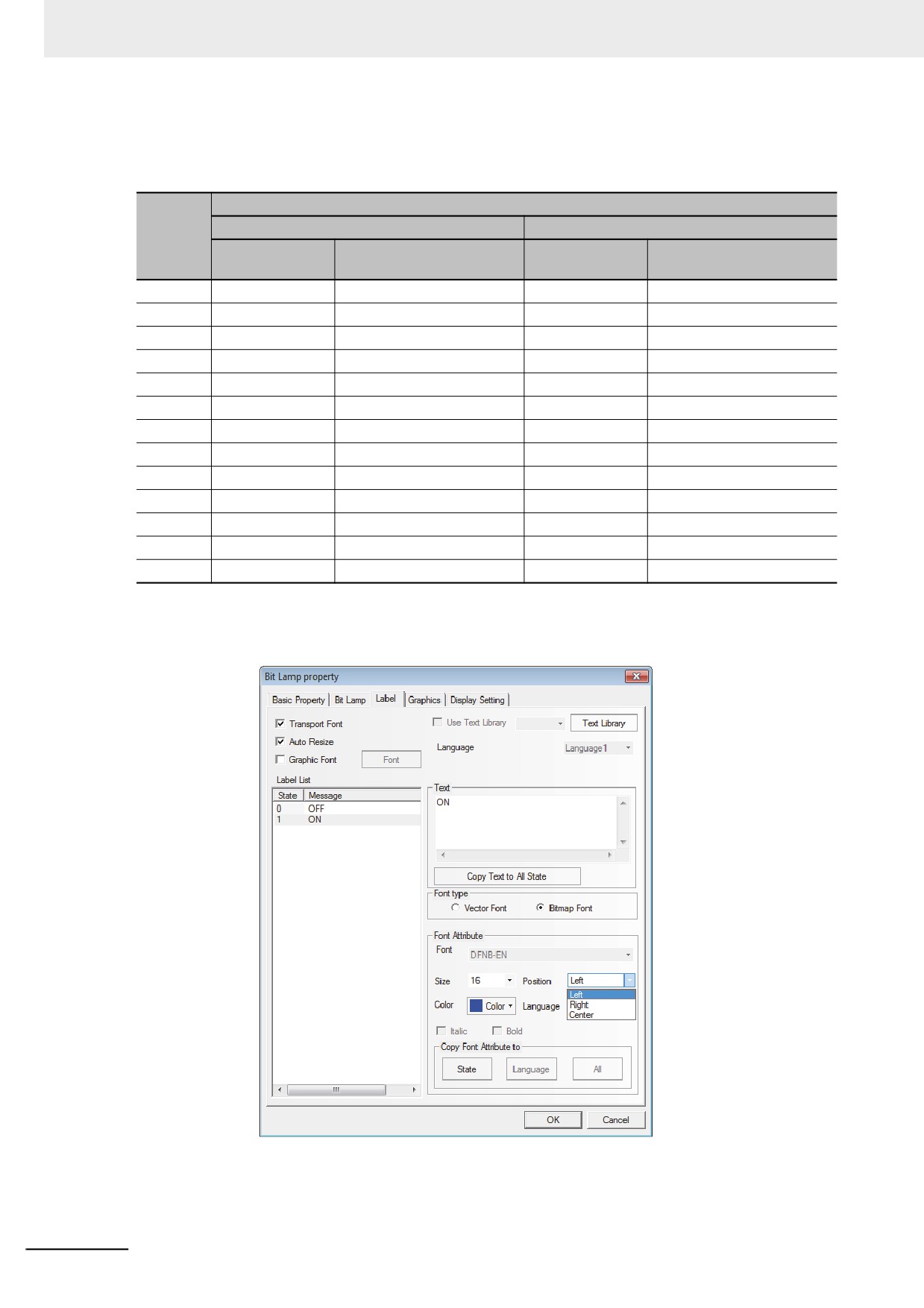
Switch to the [Label] tab and add the texts corresponding to the On and Off states.
State: Off will be displayed when the lamp state is 0; while On will be displayed when the state is 1.
Alignment: Three methods are available, as shown below:
Left: The input content is put in the left side of the graphics.
3-86
3 Functions of NB-Designer
Right: The input content is put in the right side of the graphics.
Center: The input content is put in the center of the graphics.
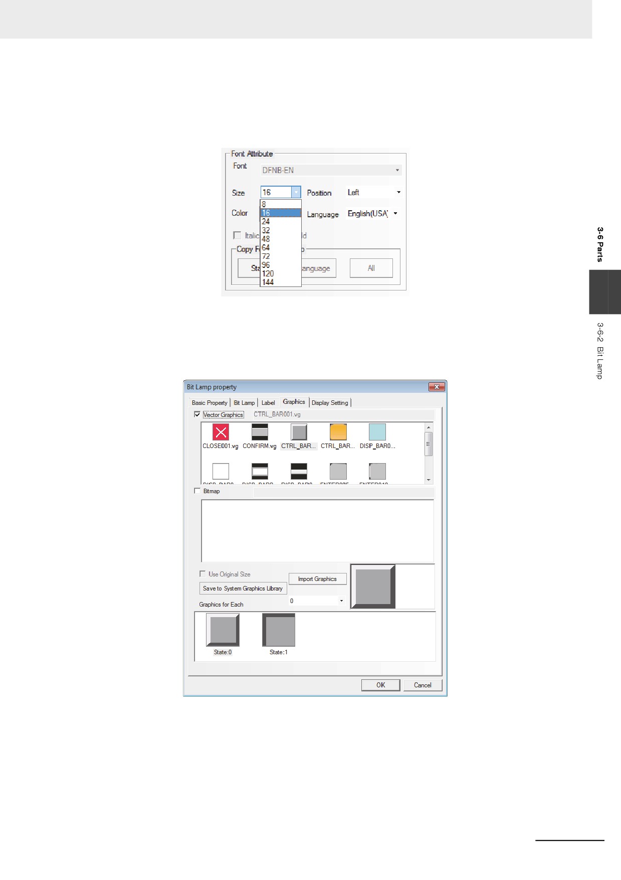
Font Size: Displays the size of the font used by the content input to “Message” and the following types
are available.
3
Color: Displays the colors of fonts used by the content input to “Message”, and the user can use
“Custom Color…” to specify the desired colors.
4
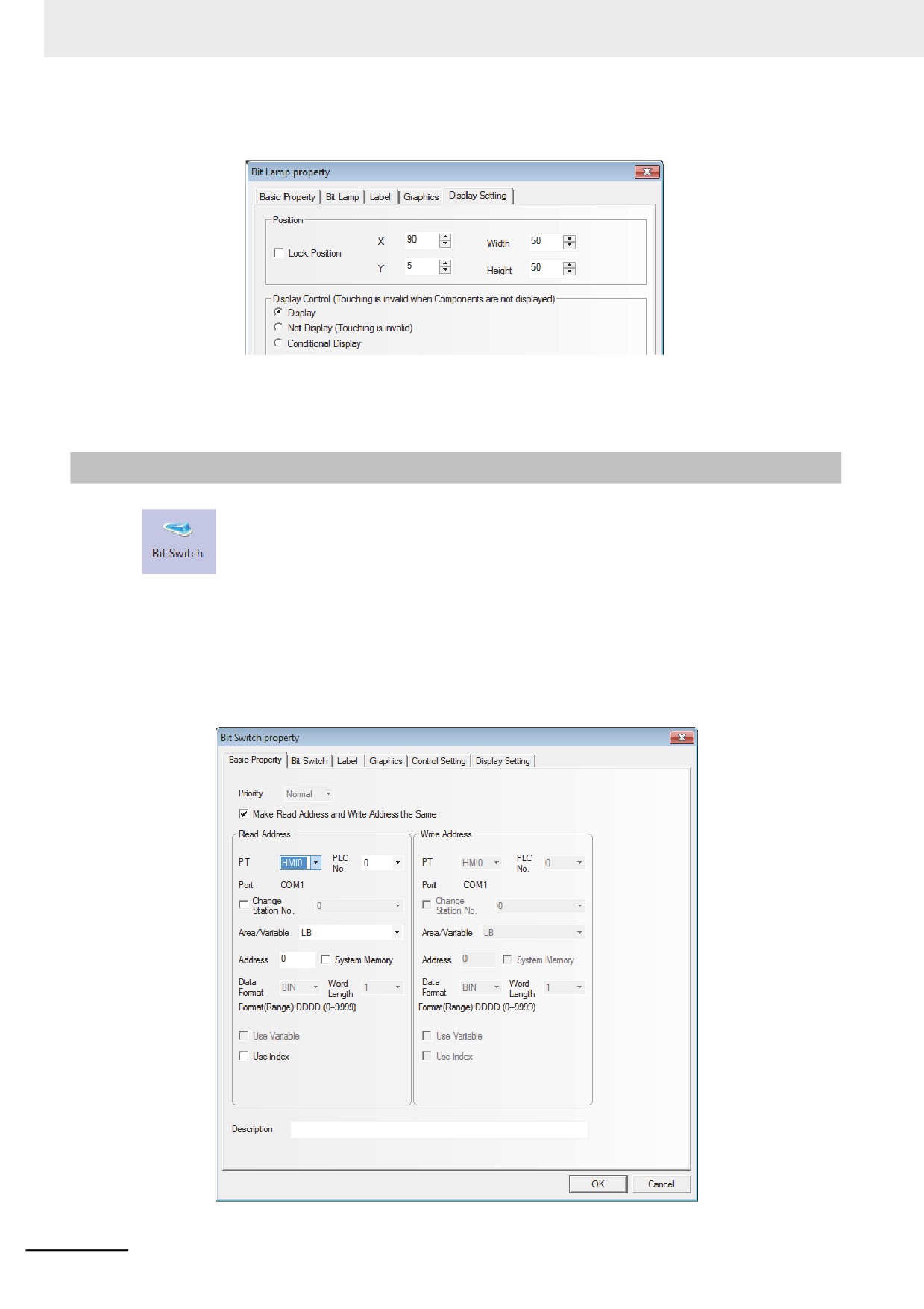
Switch to the [Graphics] tab, and select Vector Graphics or bitmap to represent the graphics
corresponding to the On and Off states of the bit address.
3-87
3 Functions of NB-Designer
5
Switch to the [Display Setting] tab and adjust the position and size of the lamp component.
6
Press the [OK] button to complete the setup of the lamp component.
3-6-3
Bit Switch
Bit Switch is the combination of the Bit Lamp and the Bit Button component. It defines a
touching area, and the bit address inside the PT or of the PLC can be switched between On and Off
state when this area is enabled.
z Process of adding one Bit Switch
1
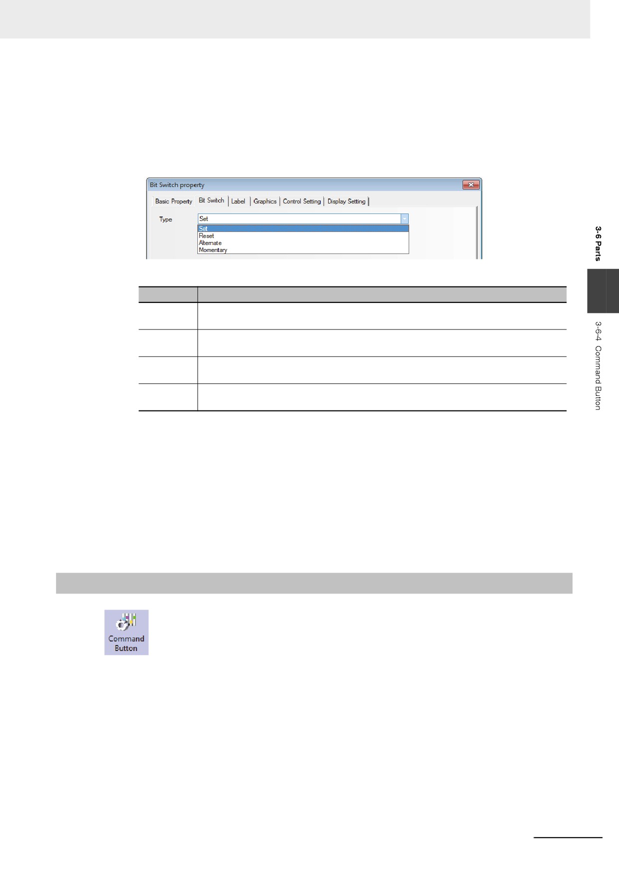
Drag the Bit Switch icon after it is pressed, then the [Basic Properties] dialog box of Bit Switch
component will pop up.
3-88
3 Functions of NB-Designer
Read Address: Bit address controls the display information of Bit Switch such as the status,
graphic, and label.
Write Address: Bit address writes the status of On or Off controlled by the Bit Switch.
Address: Refers to the Read/Write Address corresponding to the switch.
2
Switch to the [Bit Switch] tab and set switch type.
Types and Functions of Switch
3
Type
Descriptions
Set
The specified bit address will turn On when the component is pressed. The state
remains even if the component is released.
Reset
The specified bit address will turn Off when the component is pressed. The state
remains even if the component is released.
Alternate
The state of the specified bit address will change once (On˘ Off˘ On) when the
component is pressed each time.
Momentary
The specified bit address state will turn On or Off when the component is pressed or
released respectively.
3
Switch to the [Label] and add the text corresponding to the state.
4
Switch to the [Graphics] tab, and select Vector Graphics or bitmap to display the bit address
state and represent the touching area.
5
Switch to the [Control Setting] tab and make the Security Setting and set the Triggering action.
6
Press the [OK] button to complete the setup of the Bit Switch component.
3-6-4
Command Button
Command Button component also defines a touching area and the state value will be input
into the specified word address when the area is enabled.
3-89
3 Functions of NB-Designer
z Process of adding one Command Button component
1
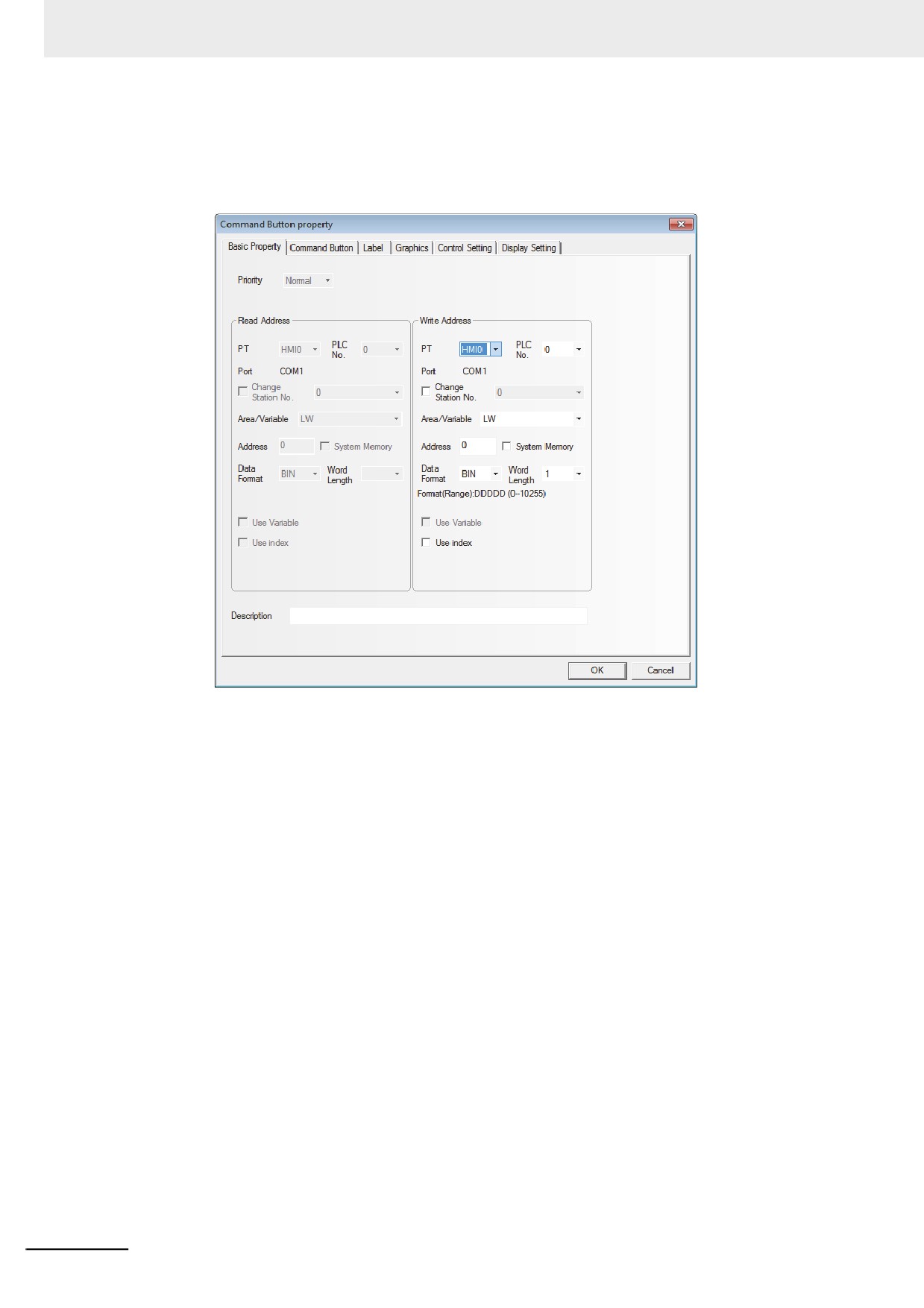
Dragging the Command Button component icon after it is pressed will make the [Basic
Properties] of Command Button component pop up.
Write Address: Refers to the word address controlling the Command Button component.
Address: The first address of word address corresponding to the Command Button component.
Word Length: Set word length of the write address. Either of 1 (single word) or 2 (double words) can
be specified.
3-90
3 Functions of NB-Designer
2
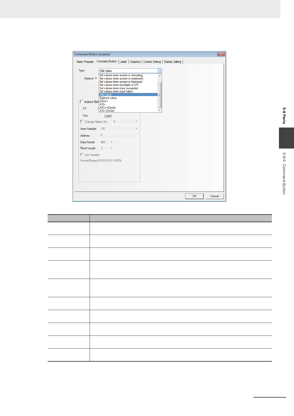
Switch to the [Command Button] tab and set the “Type” for the Command Button component.
3
Setting Mode is as follows.
Type
Descriptions
Set Values
The preset constant will be written to the specified word address when this component is
pressed. *
Set values when
The preset constant will be written to the specified word address when one screen is
screen is loading
opened. *
Set values when
The preset constant will be written to the specified word address when one screen is
screen is unloading
closed. *
Set values when
The preset constant will be written to the specified word address when the screen is
screen is
maximized. *
maximized
Set values when
The preset constant will be written to the specified word address when the screen is
screen is
minimized. *
minimized
Set values when
The preset constant will be written to the specified word address when the backlight is Off. *
backlight is OFF
Set values when
The preset constant will be written to the specified word address when the number or text is
input suceeded
input successfully. (Input the constant to be set in “Set Value”.)*
Set values when
The preset constant will be written to the specified word address when the number or text is
input failed
not input successfully. *
Add value
Each time this component is pressed, the value of the specified word address will be
increased by the “Addend” once, and its result will not exceed the “Upper”.*
Subtract value
Each time this component is pressed, the value of the specified word address will subtract
the “Subtrahend” and its result will not be less than the “Upper”.*
3-91
3 Functions of NB-Designer
Type
Descriptions
JOG++
Everytime command button is pressed for the time longer than the time to be specified
“Delay Time”, the value * set to “Addend” is added to the value of the write address with the
interval set to “JOG Speed”.
The result will not exceed the “Upper”. When [Ignore Delay Time] is checked, the “Addend”
will be added to the value of the specified word address immediately each time the
component is pressed. If this component is pressed for a long time, the “Addend” will be
added to the value of the specified word address at the interval of “JOG Speed” time until
the “Upper” is reached.
JOG--
Everytime command button is pressed for the time longer than the time to be specified
“Delay Time”, the value set to “Subtrahend” * is subtracted from the value of the write
address with the interval set to “JOG Speed”.
The result will not be less than the “Lower”. When [Ignore Delay Time] is checked, the
“Subtrahend” will be added to the value of the specified word address immediately each
time the component is pressed. If this component is pressed for a long time, the
“Subtrahend” will be added to the value of the specified word address at the interval of
“JOG Speed” time until the “Lower” is reached.
JOG++ (Circle)
Everytime command button is pressed for the time longer than the time to be specified
“Delay Time”, the value * set to “Addend” is added to the value of the write address with the
interval set to “JOG Speed”.
Until the “Upper” is reached, and then it will increase from the “Lower” again.
JOG--(Circle)
Everytime command button is pressed for the time longer than the time to be specified
“Delay Time”, the value * set to “Subtrahend” is subtracted from the value of the write
address with the interval set to “JOG Speed”.
Until the “Lower” is reached, and then it will decrease from the “Upper” again.
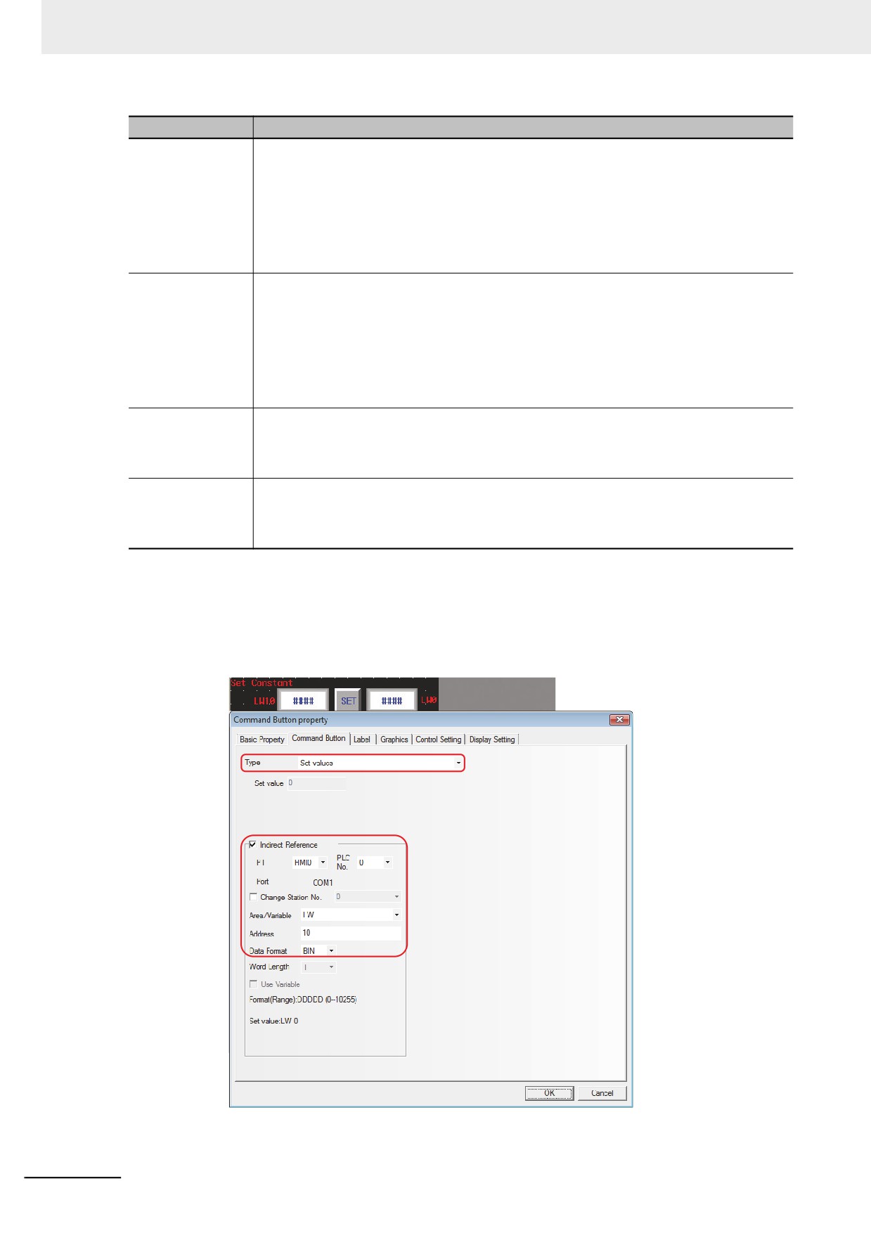
*Indirect Reference: Refers to the variables that can be used by the setting or the upper/lower limit etc.
For example:
(a) When Setting Mode is “Set Value”.
Assuming the write address of the Command Button component is LW0 with the “Type” of “Set Value”,
check [Indirect Reference] and select “LW10” as the address of variable parameter.
3-92
3 Functions of NB-Designer
The settable indirect reference values are single-WORD BIN or BCD values. The value range varies
depending on the selected data format.
BIN(unsigned)
0-65535
BIN(signed)
-32768 - 32767
BCD
0-9999
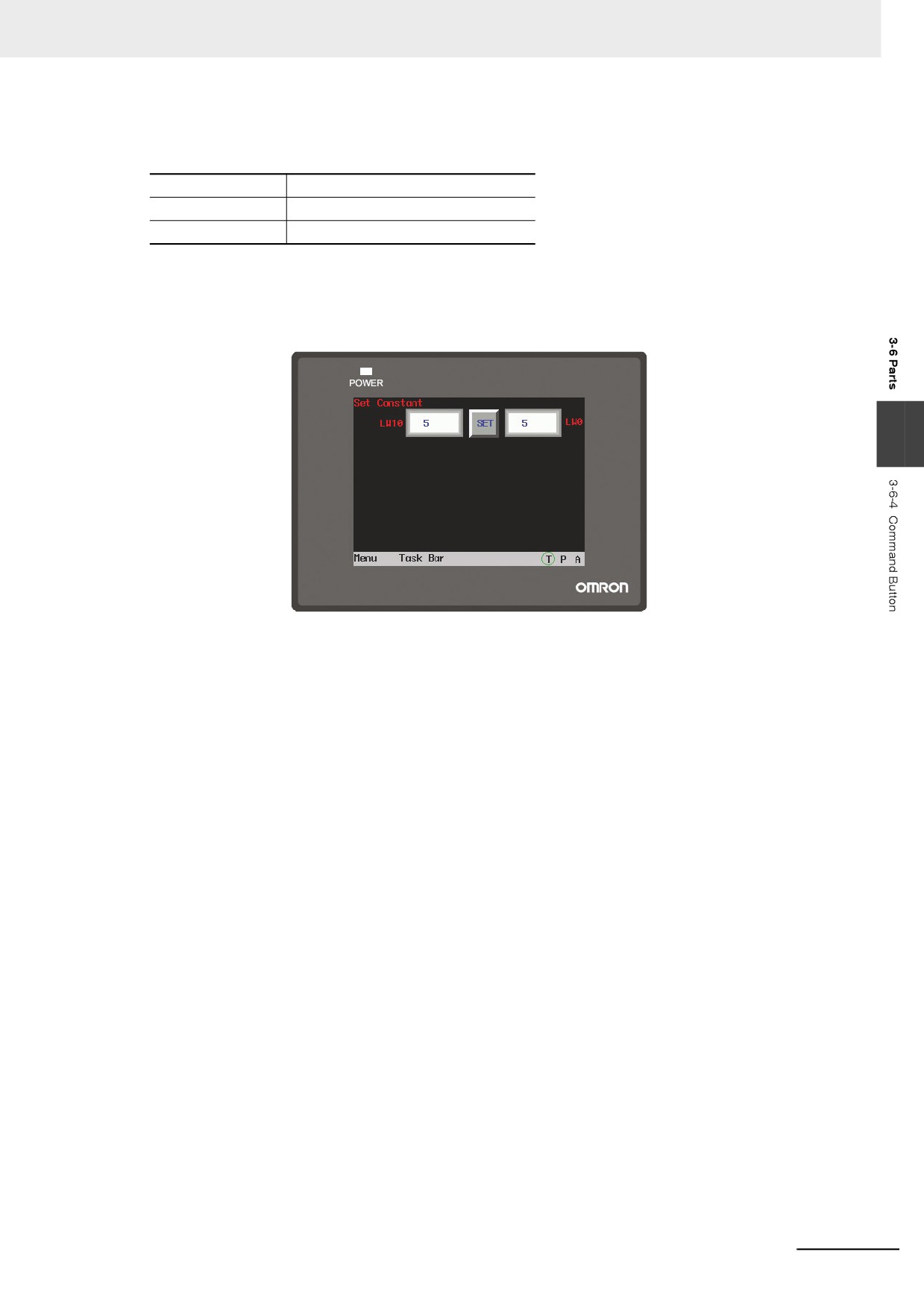
When LW10 is 5, it means the Set Value is 5. In this case, clicking “Set” will write the value of LW10
(i.e. 5) into LW0.
Perform the offline test and the effect is shown as below.
3
3-93
3 Functions of NB-Designer
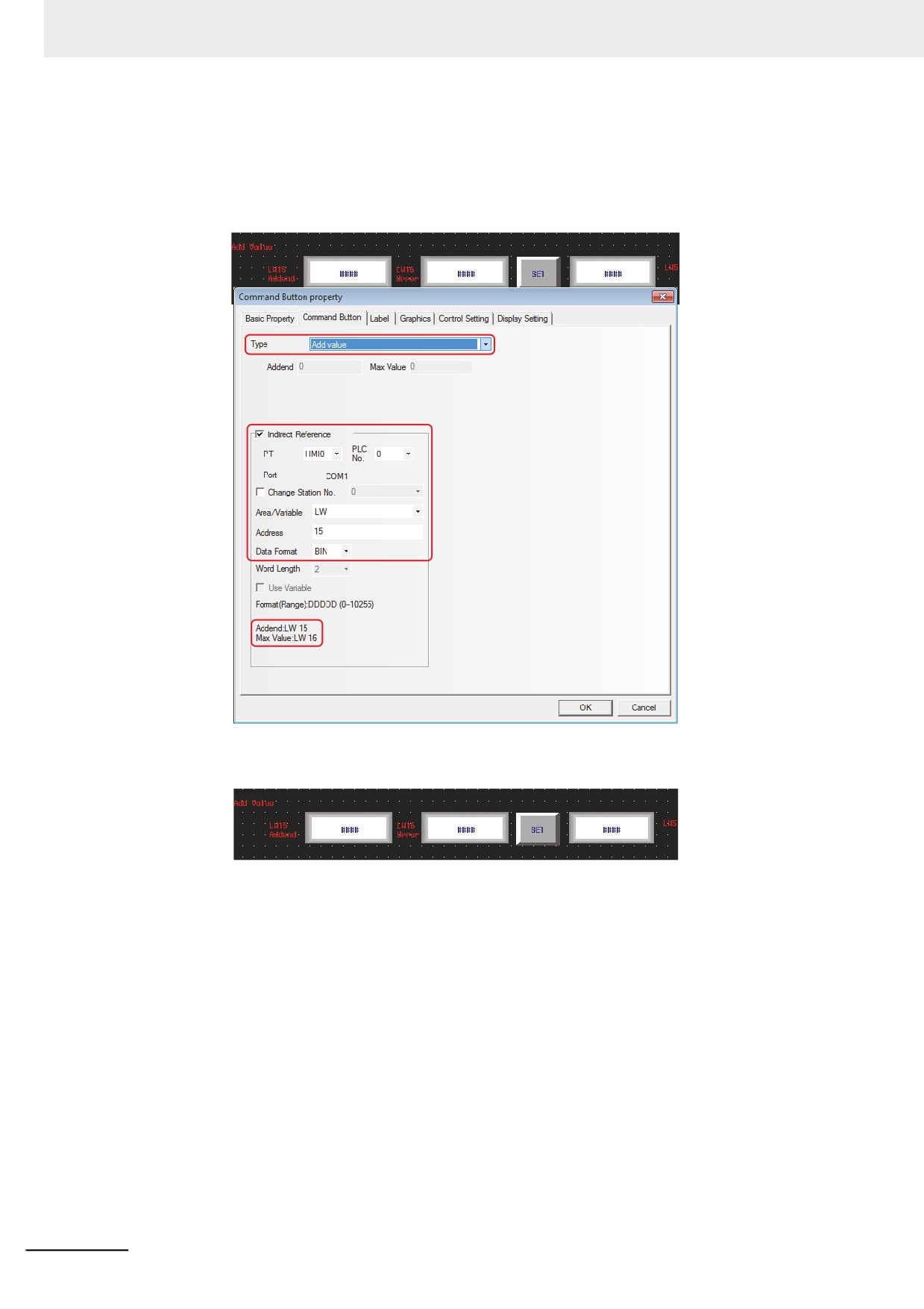
(b) When Setting Mode is “Add value”.
Assuming the write address of the Command Button component is LW5 with “Type” of “Add value”,
check [Indirect Reference] and select “LW15” and “2” as the first address of variable parameter and the
default word length respectively. The Addend address and the Upper Limit address are set by LW15
and LW16 respectively.
In addition, place 2 Number Input components with the addresses of LW15 and LW16 respectively as
well as 1 Number Display component with the address of LW5.
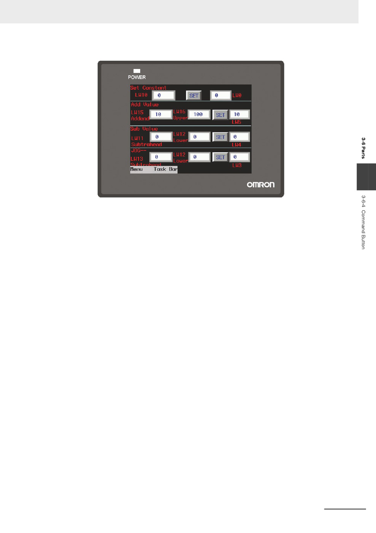
When LW15 is 10 and LW16 is 100, LW5 will increase by 10 each time when “Set” is pressed until the
upper limit (i.e. 100) is reached and then stop increase.
3-94
3 Functions of NB-Designer
Perform the offline test and the effect is shown as below.
3
3
Switch to the [Label] tab and add the text describing the state.
4
Switch to the [Graphics] tab and select Vector Graphics or bitmap to display the bit address
state and represent the touching area.
5
Switch to the [Control Setting] tab and make the Security Setting and set the Triggering action.
6
Press the [OK] button to complete the setup of the Command Button component.
3-95
3 Functions of NB-Designer
3-6-5
Word Lamp
Word Lamp is the component which will switch the display information according to the
value of the specified word address.
z Process of adding one Word Lamp component
1
Drag the Word Lamp component icon after it is pressed will make the [Basic Properties] of
Word Lamp component pop up.
Read Address: Refers to the PLC address controlling the displayed information (such as the
state, graphics, label and so on) of the Word Lamp component.
Address: The first address of word address corresponding to the Word Lamp component.
Word Length: Displays the data length of the Read Address, and 1 and 2 are available (i.e.
word or double-word).
2
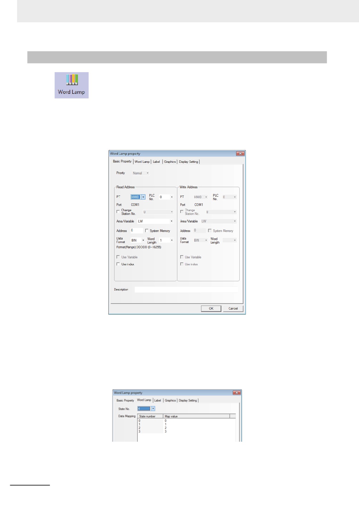
Switch to the [Word Lamp] tab and set the state for the Word Lamp component. You can set
the state from 1 to 256 in the dropdown box corresponding to “State No.”.
Map Value: Refers to the value corresponding to each state. When the value of read address
is equal to the map value, the state number corresponding to this value will be displayed.
3-96
3 Functions of NB-Designer
3
Switch to the [Label] tab and add the different displayed texts corresponding to the different
states.
4
Switch to the [Graphics] tab and select Vector Graphics or bitmap to display the graphics
corresponding to the state of the Word Lamp component.
5
Press the [OK] button to complete the setup of the Word Lamp component.
3
3-97
3 Functions of NB-Designer
3-6-6
Word Switch
Word Switch is the component which changes the status value of the value specified for
each status value and send the value to the specified address. The status value is changed by
increasing or decreasing for each touch operation or by selecting from the list. When changing the
status, the mapping value specified for each status will be sent to the specified memory. The statuses
can be set up to 256.
z Process of adding one Word Switch component
1
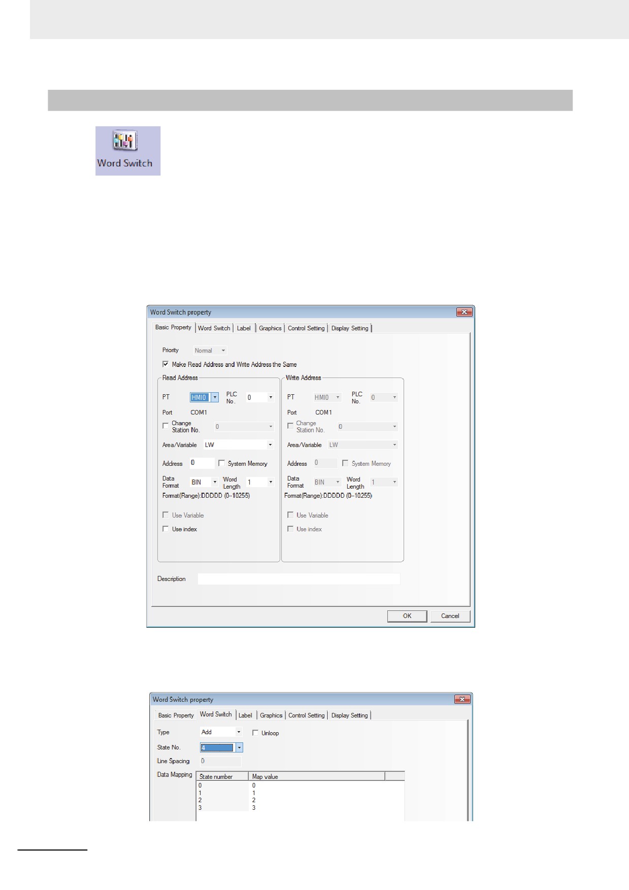
Drag the Word Switch icon after it is pressed will make the [Basic Properties] of Word Switch
component pop up.
2
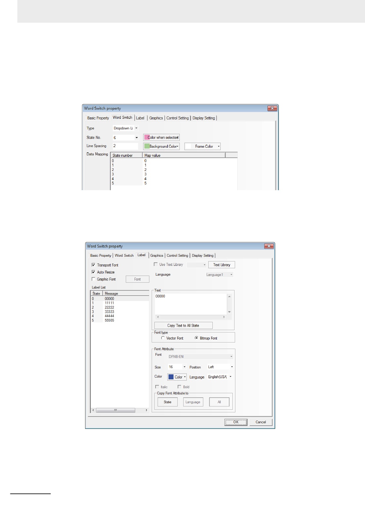
Switch to the [Word Switch] tab and set the State No. and the value corresponding to each
state for the component. You can set the state from 1 to 256 in the dropdown box
corresponding to “State No.”.
3-98
3 Functions of NB-Designer
Functions of Word Switch:
Type
Descriptions
Add
Each time this component is pressed, 1 will be added to the state number, and the map
value of the corresponding state will be written into the specified write address, and the
graphics corresponding to the state will be displayed according to the specified read
address at the same time.
Unloop: When it is checked, and the value of the memory for write address is equal to the
value mapped by the set maximum state number, the component doesn’t act when
the switch is pressed again. When it isn’t checked and the value of the memory of
write address is equal to the value mapped by the set maximum state number, the
value of the memory for write address is equal to the value mapped by the
minimum state number.
Sub
Each time this component is pressed, 1 will be subtracted from the state number, and the
map value of the corresponding state will be written into the specified write address, and
the graphics corresponding to the state will be displayed according to the specified read
address at the same time.
3
Unloop: When it is checked, and the value of the memory for write address is equal to the
value mapped by the minimum state number, the component doesn’t act when the
switch is pressed again. When it isn’t checked and the value of the memory of
write address is equal to the value mapped by the minimum state number, the
value of the memory for write address is equal to the value mapped by the set
maximum state number.
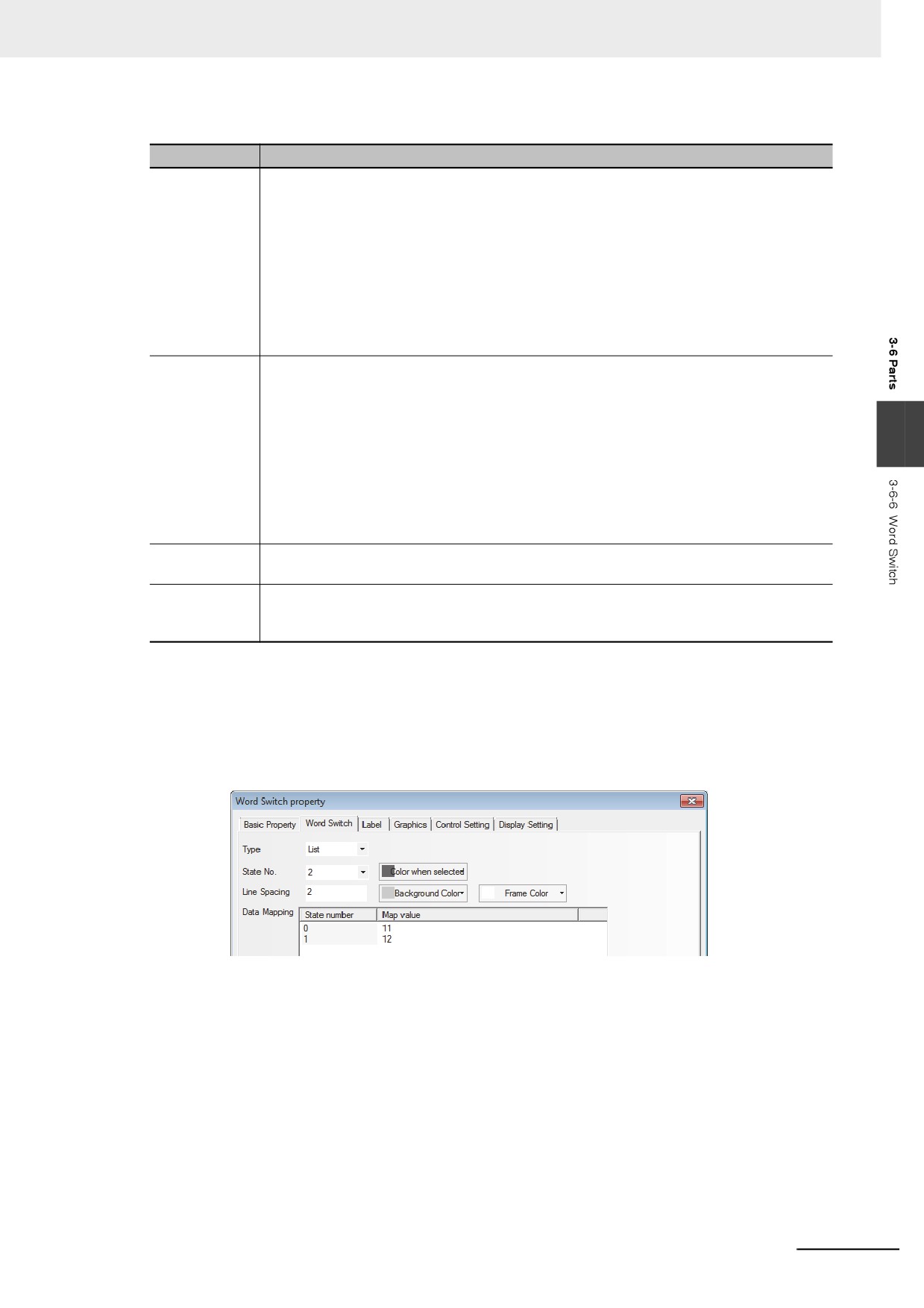
List
All the set states will be displayed in the list form, and the current state is differentiated by
the specified color.
Dropdown List
All the set states will be displayed in the dropdown list form, and the current state is
differentiated by the specified color and the first information displayed in the dropdown list
represents the current state.
For the control modes of Add and Sub, [Unloop] is not checked by default.
State No.: All 256 statuses can be set at maximum. (When BIN or BCD code and LSB code are used,
or when LSB code is used, the status of 256 (at maximum) and the status of 17 (at
maximum) will be displayed, respectively. Refer to 10 LSB Type (Page 3-379) in the section
3-16).
The line spacing for the list and the dropdown list can be set:
Map Value: When the value read by the read address is equal to a certain value in the Map Value, the
Word Switch component will display the label and the graphics corresponding to the state number of
this value. When a certain state number is switched to, the value corresponding to this value will be
written into the write address.
3
Switch to the [Label] tab and add the text corresponding to the state.
4
Switch to [Graphics] tab, and select Vector Graphics or bitmap to display the memory state and
represent the touching area.
5
Switch to the [Control Setting] tab and make the Security Setting and set the Triggering action.
3-99
3 Functions of NB-Designer
6
Press the [OK] button to complete the setup of the Word Switch component.
z List and Dropdown List
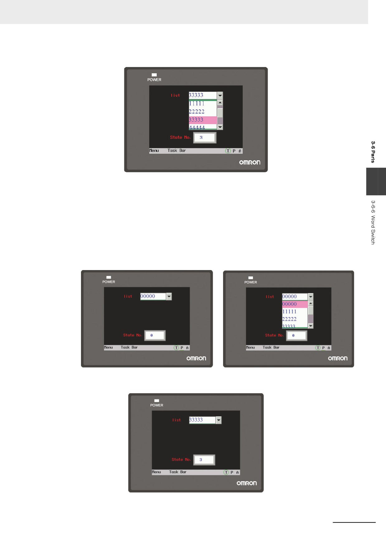
List: Refers to the value of the specified memory corresponding to the state of each option. By
default, the value of specified memory corresponding to the first option is “0”, and the value of
specified memory corresponding to the second option is “1”, and so on.
For example:
(1) Create a Word Switch in which read address and write address are LW0 and a number
display component in which address is LW0.
(2) Set the Control Mode and State No. to “List” and “6” respectively.
(3) Create the labels with the contents as shown below.
3-100
3 Functions of NB-Designer
(4) Perform the test and select “33333” in the list component, and “3” will be displayed in the
State No.
3
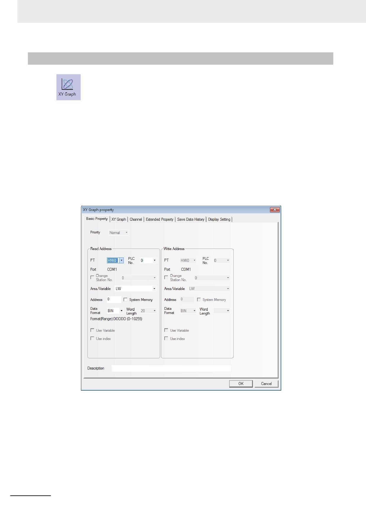
Dropdown List: When this component is touched, one list will pop up under this component. All the
options are available in this list, and it will automatically disappear when one option
is selected.
For example:
(1) Create one Word Switch with read address and write address both of LW0 and one
Number Display component with the address of LW0.
(2) Set the Control Mode and State No. to “Dropdown List” and “6” respectively.
(3) Set the label contents to “00000” to “55555”.
(4) When performing the offline test and selecting the list, the status will be displayed with a list
shown in the following figure on the right.
(5) Touch this component, and the list option will pop up as the above right graphics shown.
(6) After one option is selected, the list will disappear automatically.
3-101
3 Functions of NB-Designer
3-6-7
XY Graph
XY Graph reflects the correlation of two variables visually. If you want to monitor the XY
Graph reflecting the changes of address values, the NB Unit can clearly displayed it out only by using
this component.
When the sampling number with M channel per page is set to N, the values are stored to the PLC, e.g.
X11, Y11, X12, Y12, ..., X1N, Y1N, ..., XM1, YM1, ..., XMN, YMN. The number of the memory
addresses occupied by the PLC is M×N×2.
Note For “Xij, Yij”, subscript “i” represents the channel number, “j” represents the sampling point, and “Xij”
represents the coordinate position of X for sampling point j in channel i.
z Process of adding one XY Graph component
1
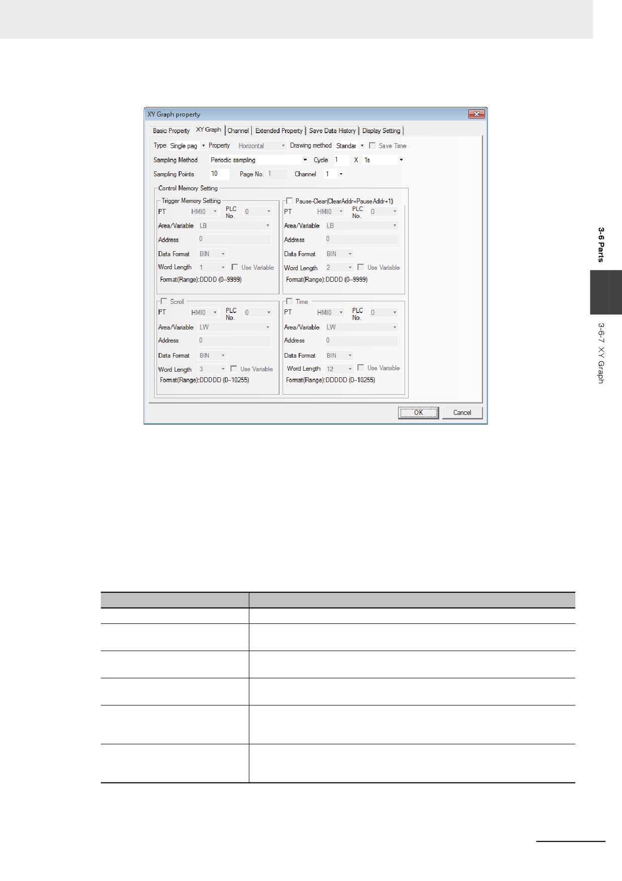
Press the XY Graph component icon, drag it to the screen, then the [Basic Properties] dialog
box of XY Graph component will pop up.
Read Address: Specifies the word address of PLC corresponding to the data of X-axis trajectory,
and the word address corresponding to Y-axis is “read address + 1”. If the channel
number is greater than 1, the addresses corresponding to the 2nd channel are as
follows: “read address +2 × sampling points” for X-axis and “read address + 2 ×
sampling point +1” for Y-axis and so on.
Address: Refers to the first address of the word address corresponding to XY Graph.
Data Format: Includes BIN or BCD.
Word Length: It is determined by the channel number, sampling points, and the type of selected
type of storing. The word length cannot be changed manually.
3-102
3 Functions of NB-Designer
2
Go to the [XY Graph] tab and set the parameters related to the XY Graph.
3
Type: Includes Single page and Multiple pages.
If “Single page” display is selected, only the data change information of the sampling value in
the current page is displayed, and the points out of the sampling points in single page will not
be saved and displayed. If “Multiple pages” display is selected, the old data can be displayed
by scrolling and the data in the past can be saved. In this way, when the XY Graph is scrolled
forward, the previous sampling data will not be lost. The history data is stored in the memory
for the reference in future.
Property (it is available option when [Trend] is selected for [Draw Type]:
Refers to the horizontal direction and vertical direction, i.e. the graphics is displayed in
horizontal direction or vertical direction when the sampling data is displayed.
Sampling Methods: They are shown as below.
Sampling Method
Descriptions
Periodic sampling
The data is sampled periodically.
OFF˘ ON trigger sampling
Only when the state of the specified bit address turns ON from OFF, the
sampling is triggered.
ON˘ OFF trigger sampling
Only when the state of the specified bit address turns OFF from ON, the
sampling is triggered.
OFF¯˘ ON trigger sampling
Only when the state of the specified bit address changes, the sampling is
triggered.
OFF˘ ON reset trigger sampling
Only the state of the specified bit address turns ON from OFF, the sampling
is triggered, and the state of the specified bit address will be reset
automatically after the triggering.
ON˘ OFF reset trigger sampling
Only the state of the specified bit address turns OFF from ON, the sampling
is triggered, and the state of the specified bit address will be reset
automatically after the triggering.
Cycle: Refers to the interval between the sampling points each 2 pages with the unit of “s” or
“100 ms”.
3-103
3 Functions of NB-Designer
DrawType: Includes Standard, Track and Trend. The sampling methods vary with the types.
Draw Type
Descriptions
Standard
Multiple points are sampled each time, and X and Y components are included.
Number of the occupied memory depends on the number of channel and sampling
points. For example, if there are m channels and n sampling points, number of the
occupied memory is “m×n×2”.
Track
One point is sampled each time, and X and Y components are included. Number of
the occupied memory depends on the number of channel. For example, if there are
m channels and n sampling points, the number of occupied memory is “m×2”.
Trend
Multiple points are sample each time, and only Y component instead of X
component is included. Number of the occupied memory depends on the number of
channel and sampling points. For example, if there are m channels and n sampling
points, number of the occupied memory is “m×n”.
Sampling Points: Refers to the number of the sampling point displayed in the screen.
PageNum: When [Multiple pages] is selected in [Type], this option is valid. And it ranges from
1 to 32767.
Channel: Refers to the number of track line to be displayed, and it corresponds to the word
length of read address to be set. And 2 word addresses correspond to one track line.
The channel ranges from 1 to 16.
Pause-Clear: Set the bit address to control the pause of creating a line graph or the clear of
creating a graph. [Clear] bit address = [Pause] bit address + 1. When [Clear] bit
is ON, the sampling data will be cleared and when the bit turns OFF again, the
sampling will continue and the changes in XY Graph will be displayed
dynamically.
Scroll: The address specified by this bit is used in combination with the scroll components, i.e.
the XY Graph can be viewed by directly moving the scroll bar. The scroll address
should be set in consistent with the address used by the related scroll bar component.
For details, refer to [3-6-22 Scroll Bar].
Time: When “Save Time” is checked, the below “Time” option can be selected. This option
includes 12 words, and it is used to save the time for the latest sampling point currently.
“Second, minute, hour, day, month, year” for the starting point and “Second, minute,
hour, day, month, year” for the end point of the current page are stored in these 12
words respectively, and each word represent a point in time.
3
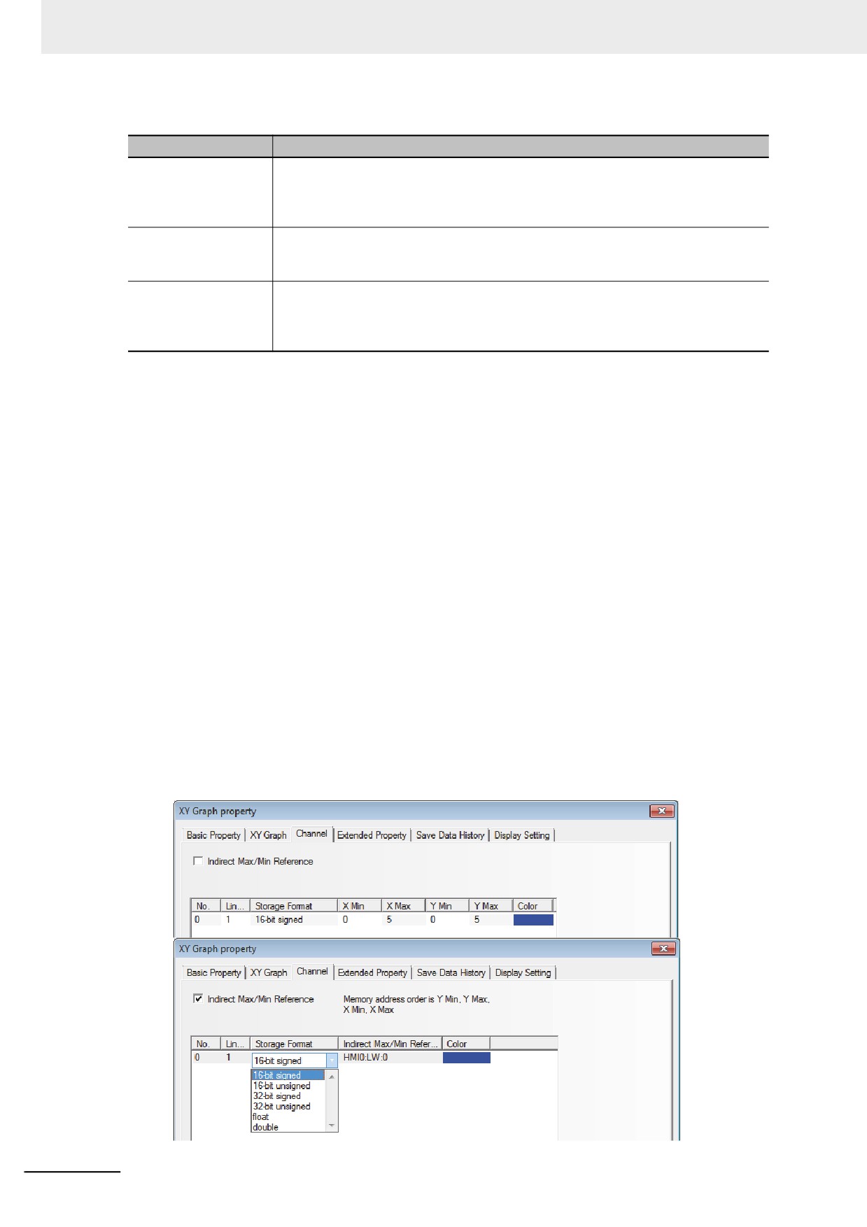
Switch to the [Channel] tab and set the parameters related to each track line.
3-104
3 Functions of NB-Designer
Color: Specifies the color for each track line.
Line Width: Refers to the thickness of the line, and 8 kinds of line width are available here.
Storage Format: Sets the data type used by the user and 6 kinds are available.
Y Min/Y Max: Sets the minimum value and maximum value of the data corresponding to each
track line in Y direction. When the read value is greater than the maximum value
or less than the minimum value, only the maximum value or minimum value will
be displayed in the XY Graph.
X Min/X Max: Sets the minimum value and maximum value of the data corresponding to each
track line in X direction. When the read value is greater than the maximum value
or less than the minimum value, only the maximum value or minimum value will
be displayed in the XY Graph.
4
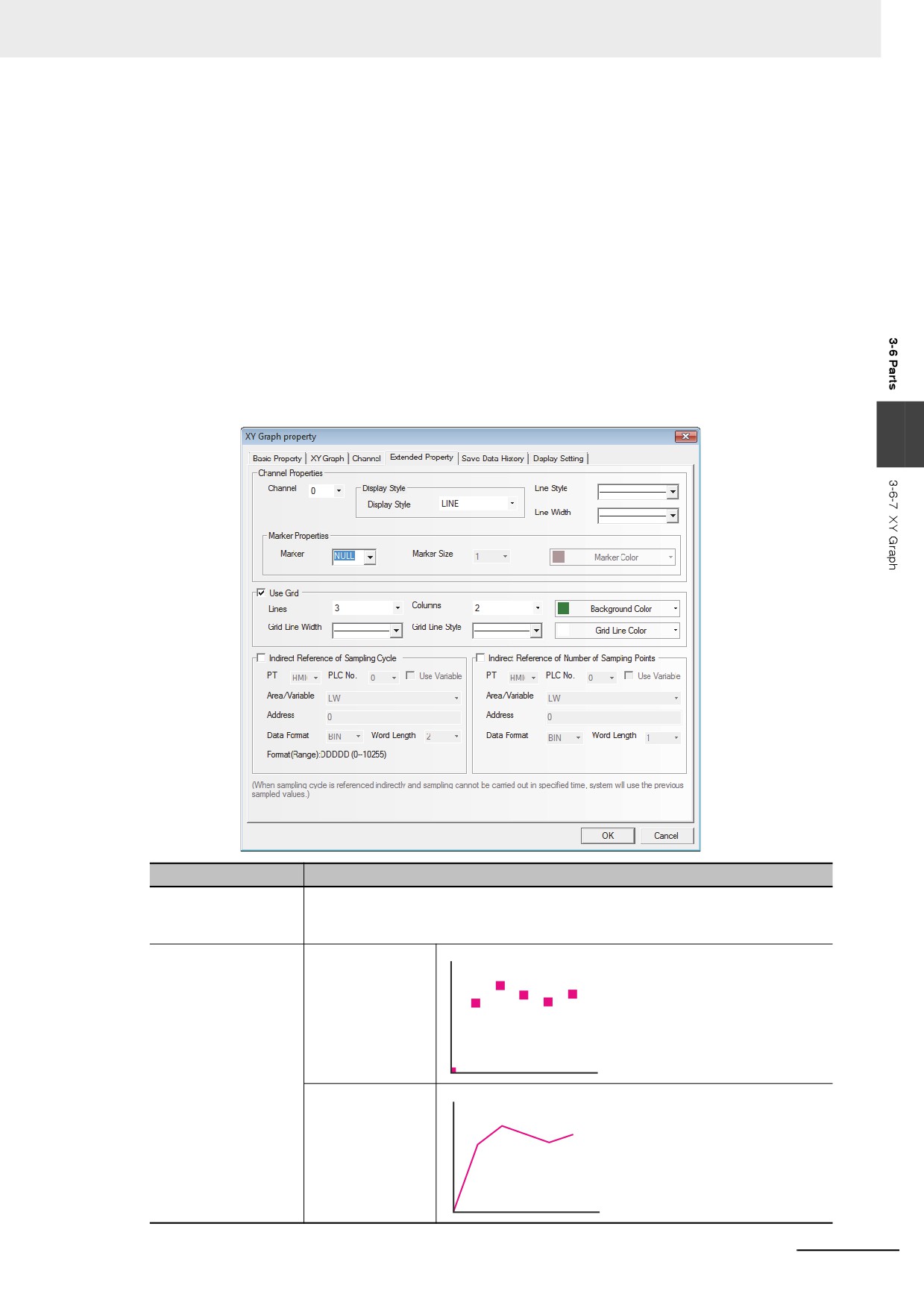
Switch to the [Extended Properties] tab and set Channel Properties, Grid Properties and
Variable Period etc.
3
Extended Properties
Descriptions
Channel Properties
Select the channel to be edited. The optional channel depends on the channel
number set in “Data Log” Property tab. And the set the Line Style and Line Width of
track line corresponding to the channel.
Display Style
Dot
LINE
3-105
3 Functions of NB-Designer
Extended Properties
Descriptions
Connect Type
X axis projection
Y axis projection
Marker Properties
Select the Marker graphics from the 7 available graphics z {
×.
Marker Size
Sets the size of Marker.
Marker Color
Sets the color of Marker.
Use Grid
Checking this option means the Data Log will use the background and grid effect
provided by the system, and the lines and columns of the grid to be displayed and
the color, width and type of grid line, etc. can be set respectively.
Indirect Reference of
When periodical sampling is used, the sampling time will be read from the specified
Sampling Cycle
memory.
Indirect Reference of
The sampling points will be read from the specified address.
Number of Sampling
Points
5
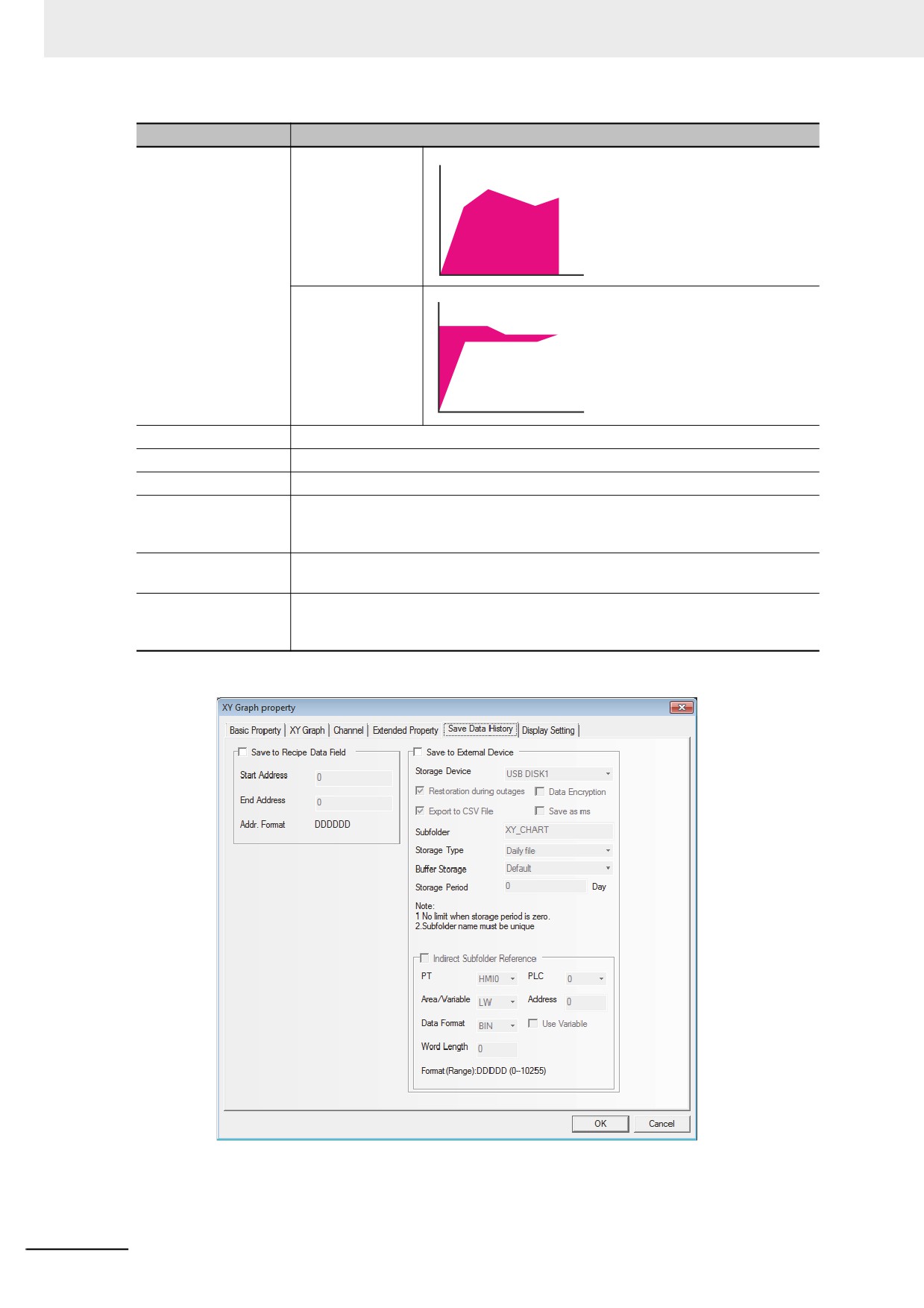
Switch to the [Save Data History] tab and set information to be saved.
Save to Recipe Data Field: Checking this option means the data will be saved into the
address of memory for recipe memory in the PT (i.e. RW
memory).
3-106
3 Functions of NB-Designer
The area used for storing data can be calculated with those formulas as follows.
Standard or Track:
20 + Sampled pages x 4 + Sampled pages x Sampled points x Number of
Channels x 2
Trend:
20 + Sample pages x Sampled points x 4 + Sampled pages x Sampled
points x Number of Channels
6
Press the [OK] button to complete the setup of the XY Graph component.
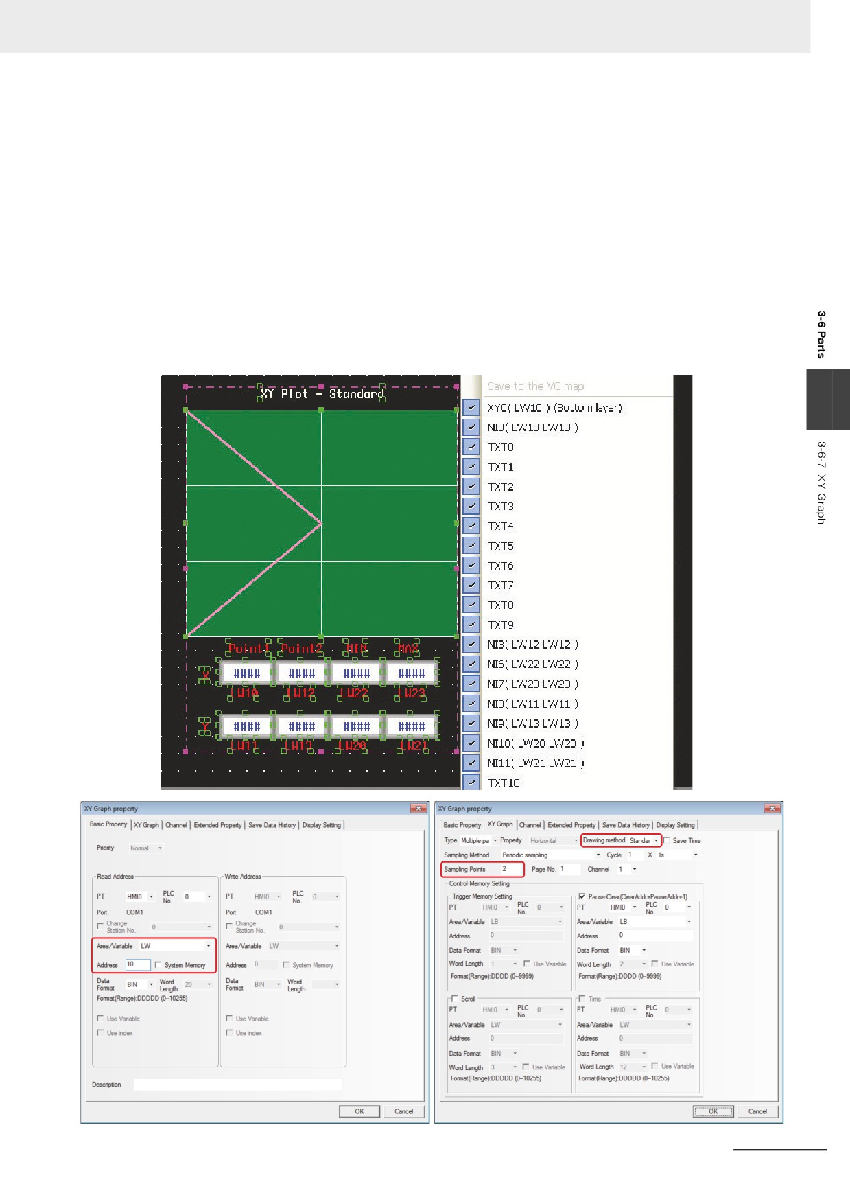
Example: When the maximum value and minimum value of a line graph (Drawing method:
Standard) are specified indirectly.
Descriptions: The coordinate position of sampling point 1 and sampling point 2 correspond to
“x, y (LW10, LW11)” and “x, y (LW12, LW13)”; and the minimum values and
maximum values of y coordinate and x coordinate are LW20 & LW21 and LW22
& LW23 respectively.
3
3-107
3 Functions of NB-Designer
Y coordinate min = LW20; Y coordinate max = LW21
X coordinate min = LW22; X coordinate max = LW23
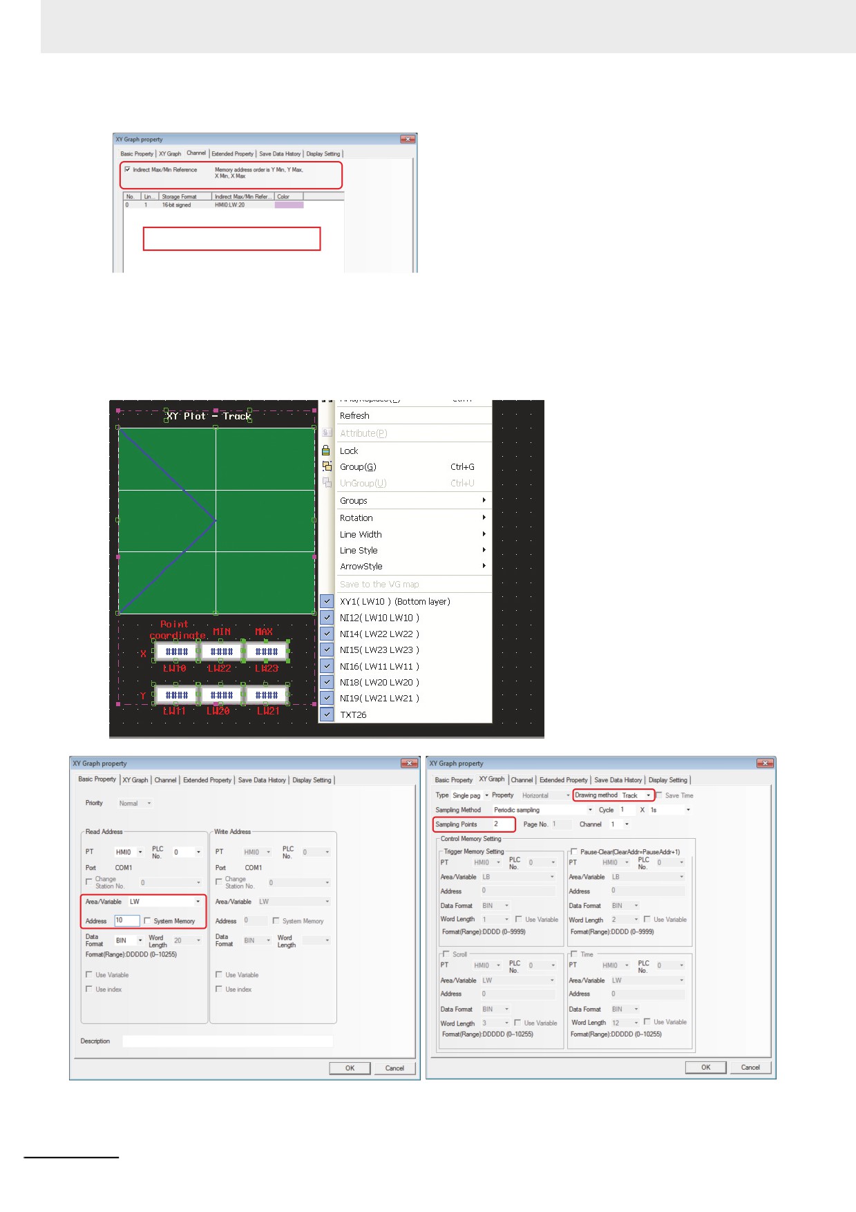
Example: When the maximum value and minimum value of a line graph (Drawing method:
Track) are specified indirectly.
Descriptions: The position coordinate is allocated as below.
There is only 1 sampling point whose coordinate value corresponds to “x, y”
(LW10, LW11), and the minimum values and maximum values for y coordinate
and x coordinate are “ LW20 & LW21” and “LW22, LW23” respectively.
3-108
3 Functions of NB-Designer
Y coordinate min = LW20; Y coordinate max = LW21
X coordinate min = LW22; X coordinate max = LW23
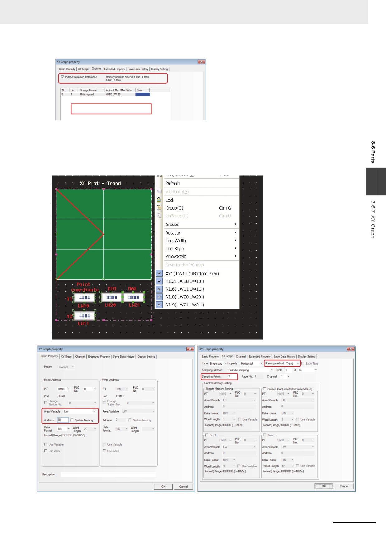
Example: When the maximum value and the minimum value of a line graph (Drawing method:
Trend) are specified indirectly.
Descriptions: The position coordinate is allocated as below:
There are 2 sampling points corresponding to y1 (LW10) and y2 (LW11), and
LW20 and LW21 correspond to the minimum (lower limit of Y) and the maximum
value (upper limit of Y) respectively.
3
3-109
3 Functions of NB-Designer
Y coordinate min = LW20;
Y coordinate max = LW21
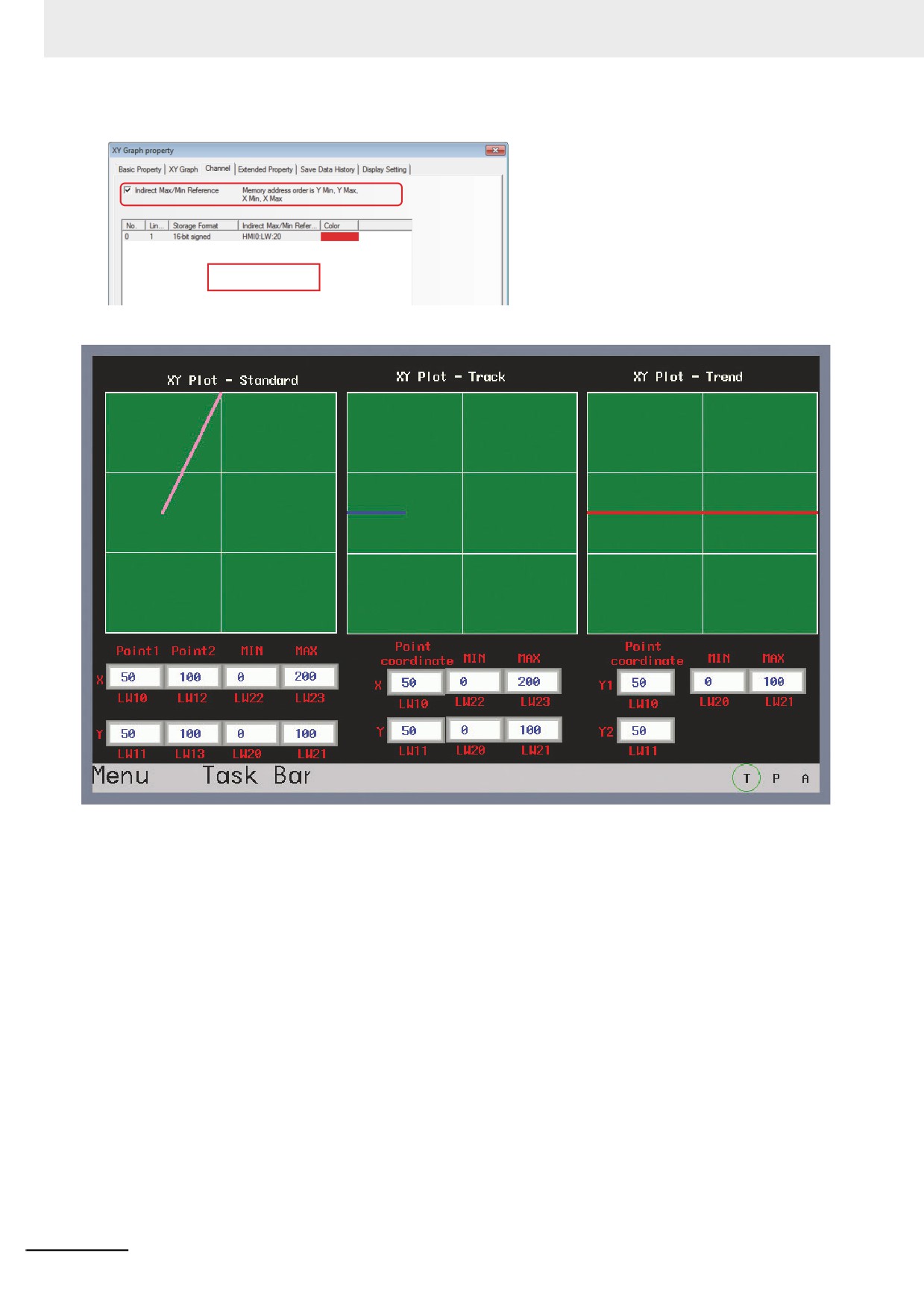
Perform the test and the effect is as shown below.
3-110
3 Functions of NB-Designer
3-6-8
Moving Component
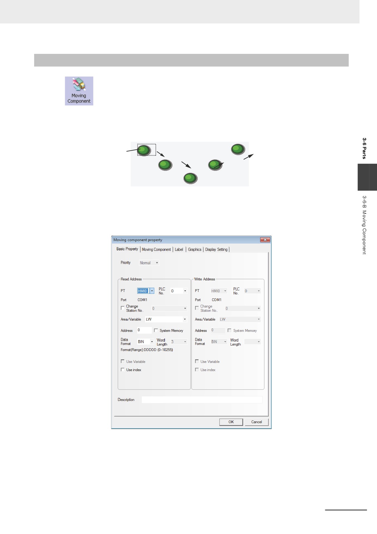
Moving Component can be used to put one Vector Graphics or bitmap into the position
specified by PLC in the PT. The state and absolute position are provided by the 3 consecutive
memories in PLC. The read address controls the status of the component, the address of the Read
Address + 1 controls the coordinate position X, and the address of the Read Address + 2 controls the
coordinate position Y.
3
z Process of adding one Moving Component
1
Press the Moving Component icon, drag it to the screen, then the [Basic Properties] dialog box
of the Moving Component will pop up.
Read Address: Controls the first address of the word address controlling the displayed
information (such as the state, graphics, label and so on) of the Moving
Component in PLC.
Address: Refers to the first address of the word address corresponding to the Moving
Component.
Word Length: Displays the data length of the read address, which is fixed to “3”.
3-111
3 Functions of NB-Designer
2
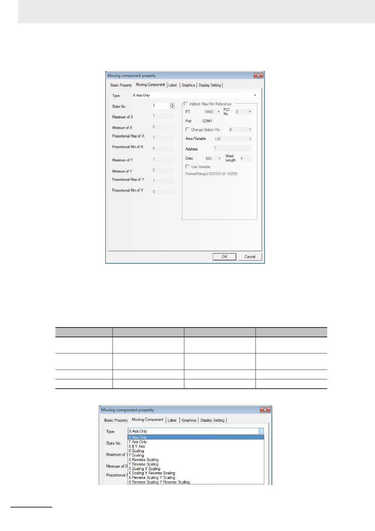
Switch to the [Moving Component] tab and set the Type, State Number, the Minimum of X,
Maximum of X, Minimum of Y and Maximum of Y.
Type and Function Tables:
NB-Designer can assign up to 256 kinds of different states to the components. When State
Number is set to "1" in the tab [Moving Component], make sure that the stored value specified
to the [Read Address] is 0. Otherwise, the components will not be displayed, States 1 to 256
correspond to the internal values of 0 to 255. The position control is as shown below, and its
position is relative to the original position (X-axis and Y-axis represent abscissa and ordinate
respectively.)
Control Mode
X
Y
X & Y
Number of Read
2 words
2 words
3 words
Address
Read Address
States of Vector Graphics
States of Vector Graphics
States of Vector Graphics
or bitmap
or bitmap
or bitmap
Read Address + 1
X-axis displacement
Y-axis displacement
X-axis displacement
Read Address + 2
-
-
Y-axis displacement
The Type includes the items as follows.
3-112