OMRON NB-Designer OPERATION MANUAL (NB-series, 2020) - page 3
3 Functions of NB-Designer
z Text
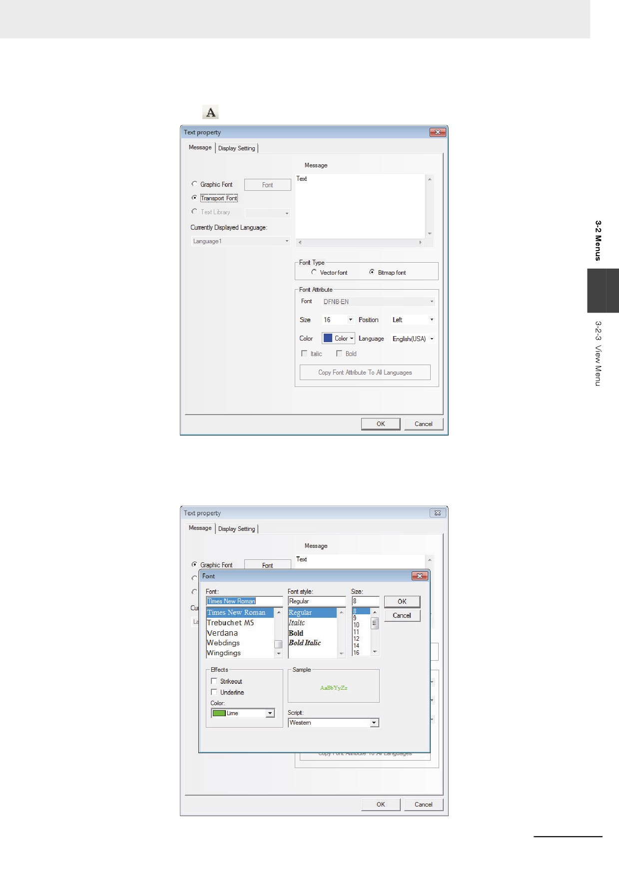
After the text icon
being pressed, the text dialog box will pop up, as shown below.
3
Message: Enter the text which will be displayed on the component. You can use the “Enter” key to
break the input text.
Graphic Font: The font and its size and style etc can be modified in this mode. The Modify dialog box,
as shown below, can be entered by clicking the “Font” on the right side of “Graphic Font”.
3-23
3 Functions of NB-Designer
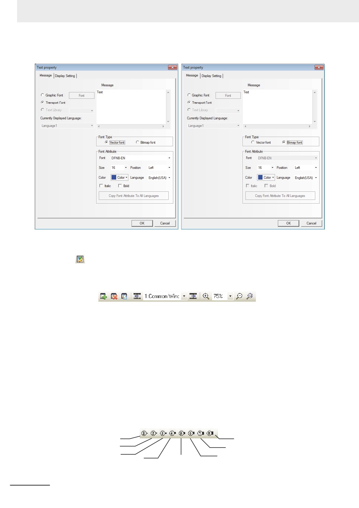
Transport Font: In this mode, both Vector Font and Bitmap Font can be used, and the font size,
alignment method or color etc can be changed.
z Load Graphic
The
icon can be used to add the graphic when you create a new bitmap. For the creation of the
bitmap, refer to 3-5-6 Bitmap (Page 3-65).
z Screen Toolbar
[Add Screen]: To add the Edit Window
[Delete Screen]: To delete the current Edit Window
[Current Screen Property]: To display the Properties of the current Edit Window
[Previous Page]: The previous Edit Window
[Current Page]: The title of the current Edit Window
[Next Page]: The next Edit Window
[Magnify]: To magnify in the current Edit Window
[Zoom]: 100%, 200%, and 300% available
[Dwindle]: To dwindle the current Edit Window
[1:1]: The current Edit Window displayed in 100%
z Line Style Toolbar
1p
8p
2p
7p
3p
6p
4p
5p
They are used for the selection of line width
3-24
3 Functions of NB-Designer
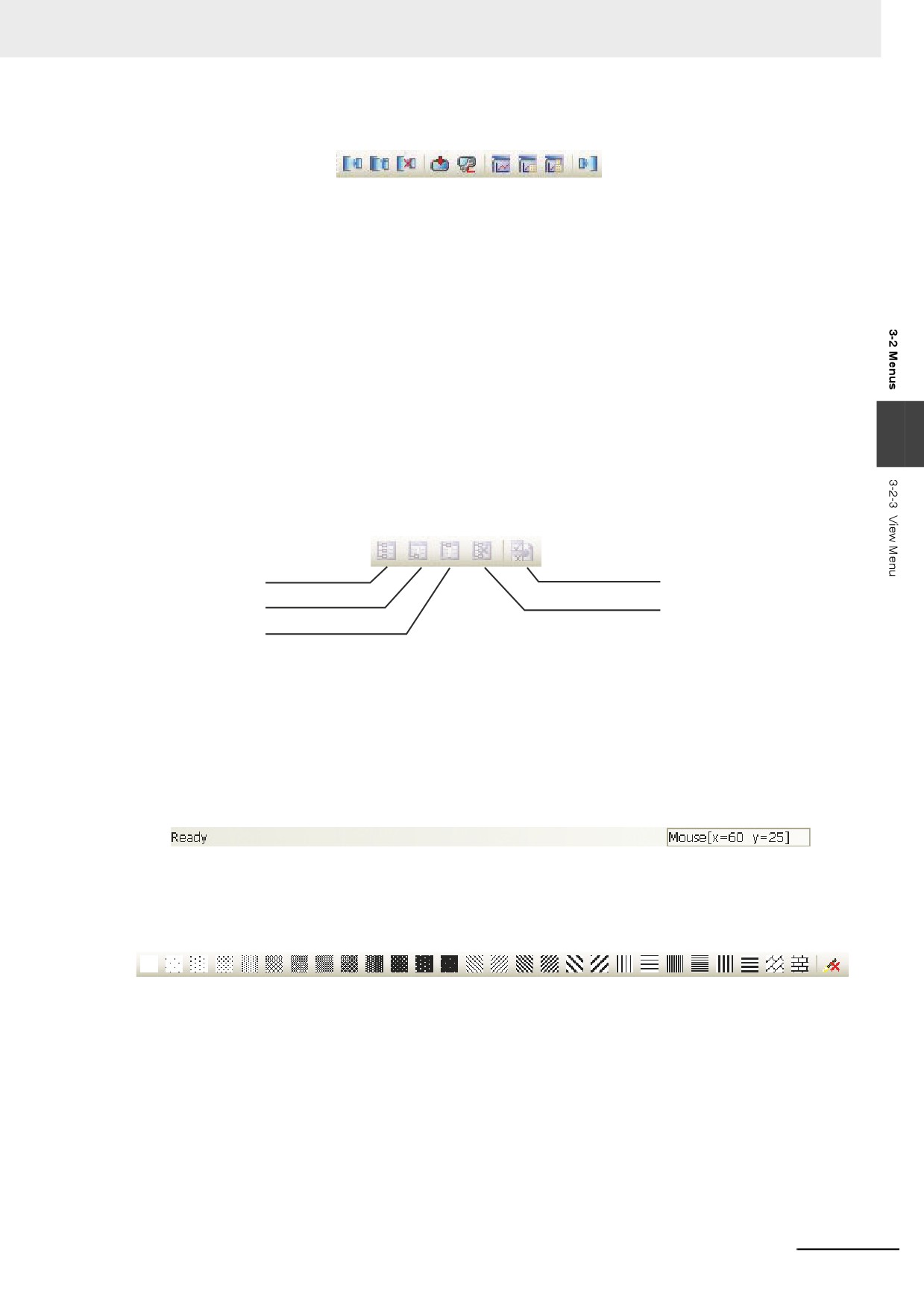
z System Toolbar
[Compile]: To only compile the parts with changes in the current project and to check whether there
is an error or not. The project must be compiled before the download or test. otherwise the
download or test will fail.
[Recompile]: To recompile the items in the current project
[Clear Compiled Result]: To clear the result of the current project
[Download]: To download the project into PT
[Transmission Setting]: To set the transmission method. Either of the Ethernet, USB port, or serial
port can be set.
[Offline test]: To perform offline test of the project
[Indirect Online test]: To perform online test of the project indirectly
3
[Direct Online test]: To perform online test of the project directly
[Decompile]: To decompile the project
z
Code Edit Toolbar
Macro
New
Bookmark
Variable Table
Next Bookmark
Delete Bookmark
Previous Bookmark
[New Bookmark]: To create a new bookmark
[Next Bookmark]: To check the next bookmark
[Previous Bookmark]: To check the previous bookmark
[Delete Bookmark]: To delete the bookmark
[Macro Variable Table]: To open or close the Macro Variable Table
z
Status Bar Toolbar
Displays the information such as the current mouse position, the width/height of the destination
object and editing state etc.
z Pattern Toolbar
Select one fill effect among various styles as above to set to the drawing components or Edit
Window.
3-25
3 Functions of NB-Designer
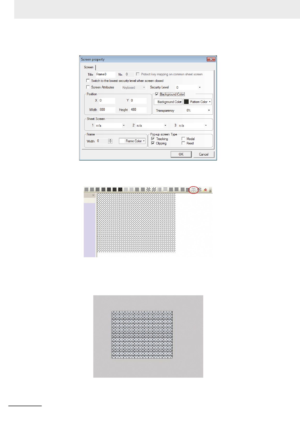
In order to set the fill effect to the displayed window, double-click the window and check “Use
Background Color” in the displayed “Screen Property”, as shown below.
Then select the pattern color and the background color as well as the fill effect you want, as shown
below.
In order to add fill effect to the shapes, select the shape to add fill effect and select the fill effect. The
procedure to set the fill effect is the same as the one for adding fill effect to the PT. But when setting
the fill effect to the components, [Pattern Color] is applied to the outline color and [Background color]
is applied to the component's color. The parameters set to the shape is reflected as below.
3-26
3 Functions of NB-Designer
3-2-4
Screen Menu
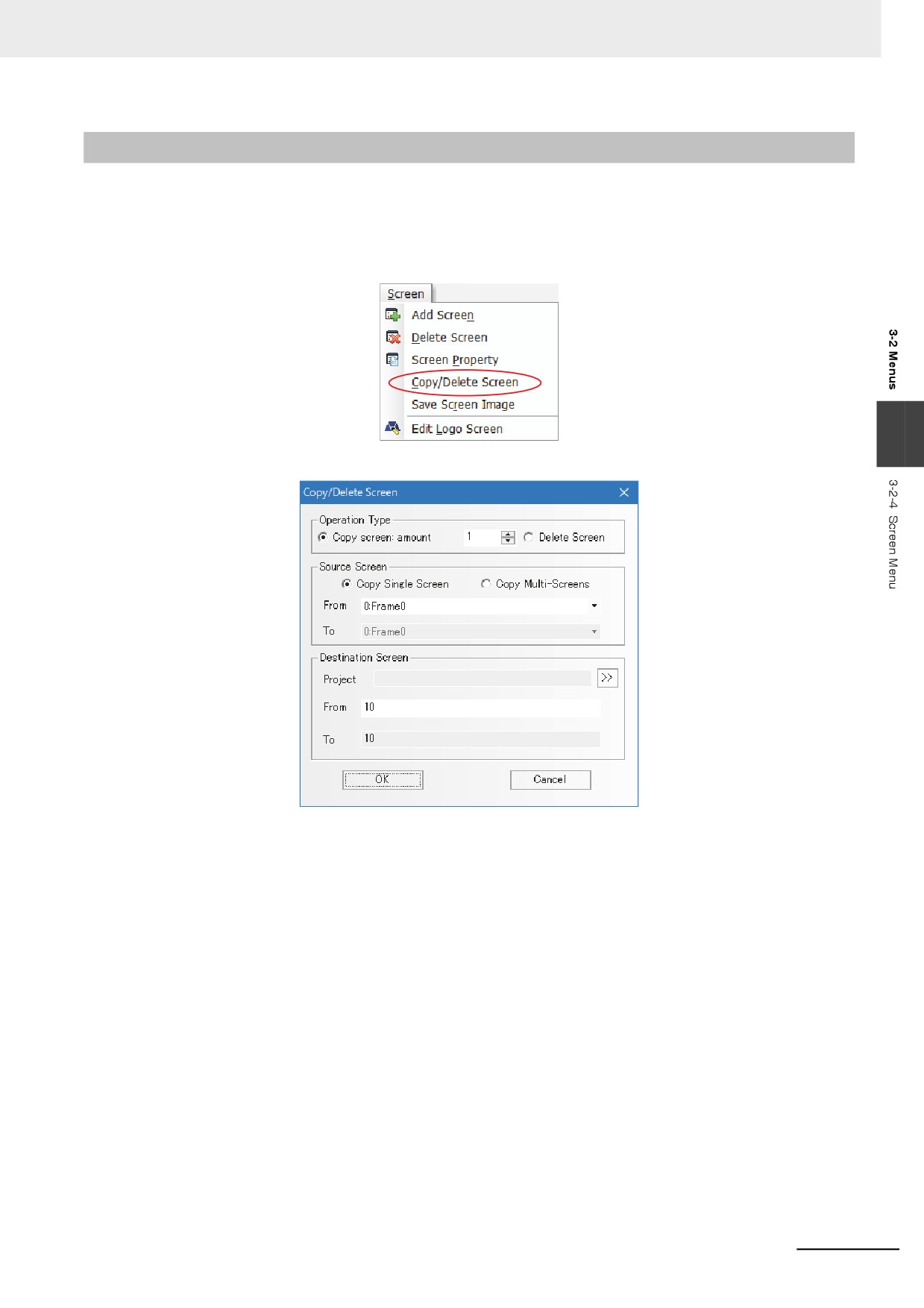
The corresponding contents in the [Screen] menu shown as below have been described in [3-2-3 View
Menu], here only the function of [Copy/Delete Screen] and [Save Screen Image] are described in
details.
z Copy/Delete Screen
3
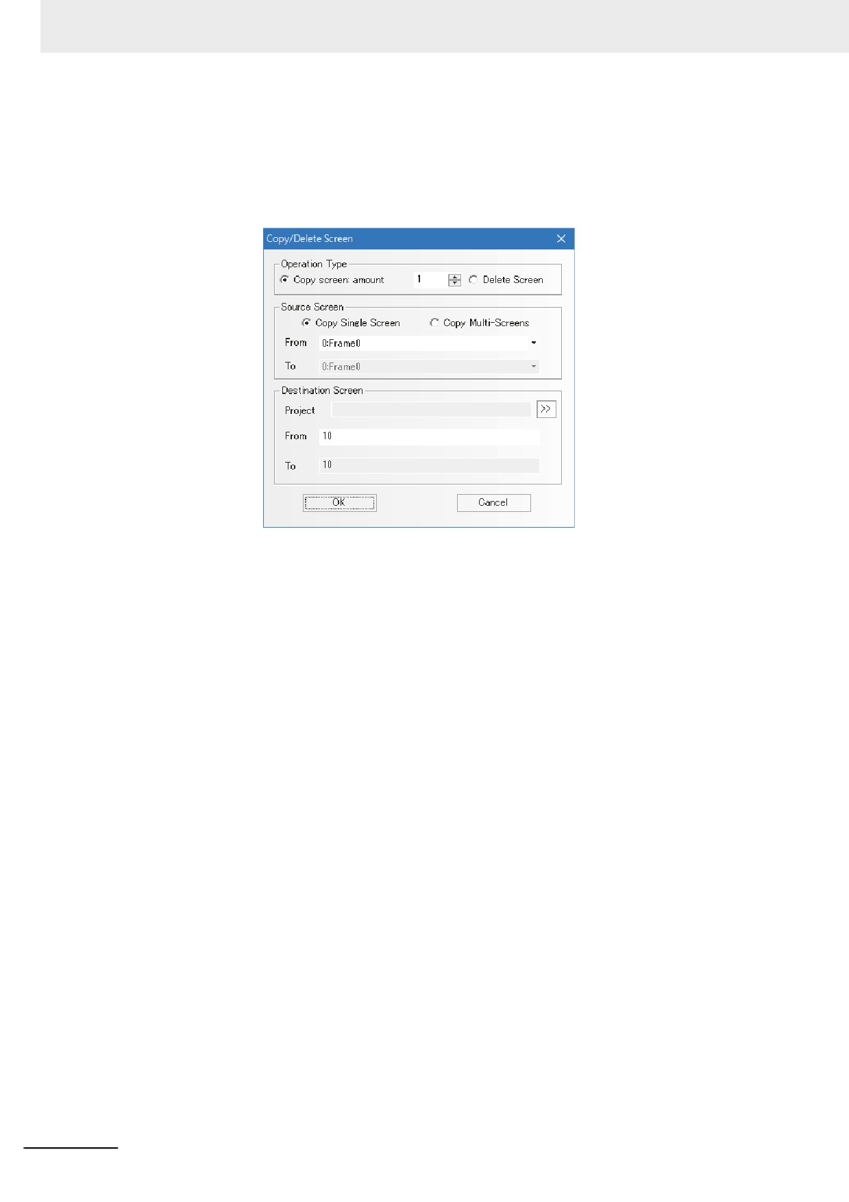
Click [Screen]˘ [Copy/Delete Screen], and the following dialog box will be displayed.
z Operation Type
(1) Copy Screen
It can be one or more and its range is between 1 and 999.
• Copy Single Screen
When the number is 1, both the starting source screen ID and the starting destination screen ID
can be set, which means the screen and Properties of the source screen will be copied into the
destination screen.
If the destination screen doesn’t exist, the screen with a specified number will be created
automatically after the copy operation. And if the destination screen exists already, “Copy error: the
destination screen ID already exists!” will prompt.
3-27
3 Functions of NB-Designer
When the number is greater than 1, both the starting source screen ID and the starting destination
screen ID can be set, and the destination screen ID will increase automatically according to the
copied number in this case, which means the screen and Properties of the source screen will be
copied into the screens between the starting destination screen and the end destination screen
respectively.
• Copy Multi-Screens
When the number is 1, both the starting source screen ID, the end source screen ID and the
starting destination screen ID can be set, and the end destination screen ID will increase
automatically according to the number of the source screen, which means the screens and
properties of the screens between the starting source screen and the end source screen will be
copied in order into the screens between the starting destination screen and the end destination
screen respectively.
When the copy number is greater than 1, the starting source screen ID, the end source screen ID
and the starting destination screen ID can be set, and the end destination screen ID will increase
automatically according to the copied number and the number of the source screen, which means
the screens and properties of the screens between the starting source screen and the end source
screen will be copied in order and as specified number into the screens between the starting
destination screen and the end destination screen respectively.
• Copy and Paste to Other Project
Screens of a project can be copied and pasted to other project by specifying the project in [Project].
Copied screens are pasted to the destination project given the screen numbers which begin with
the next number of the last screen number.
Note The destination screen ID must be a new screen ID because the existing screen ID doesn’t support the
screen copy.
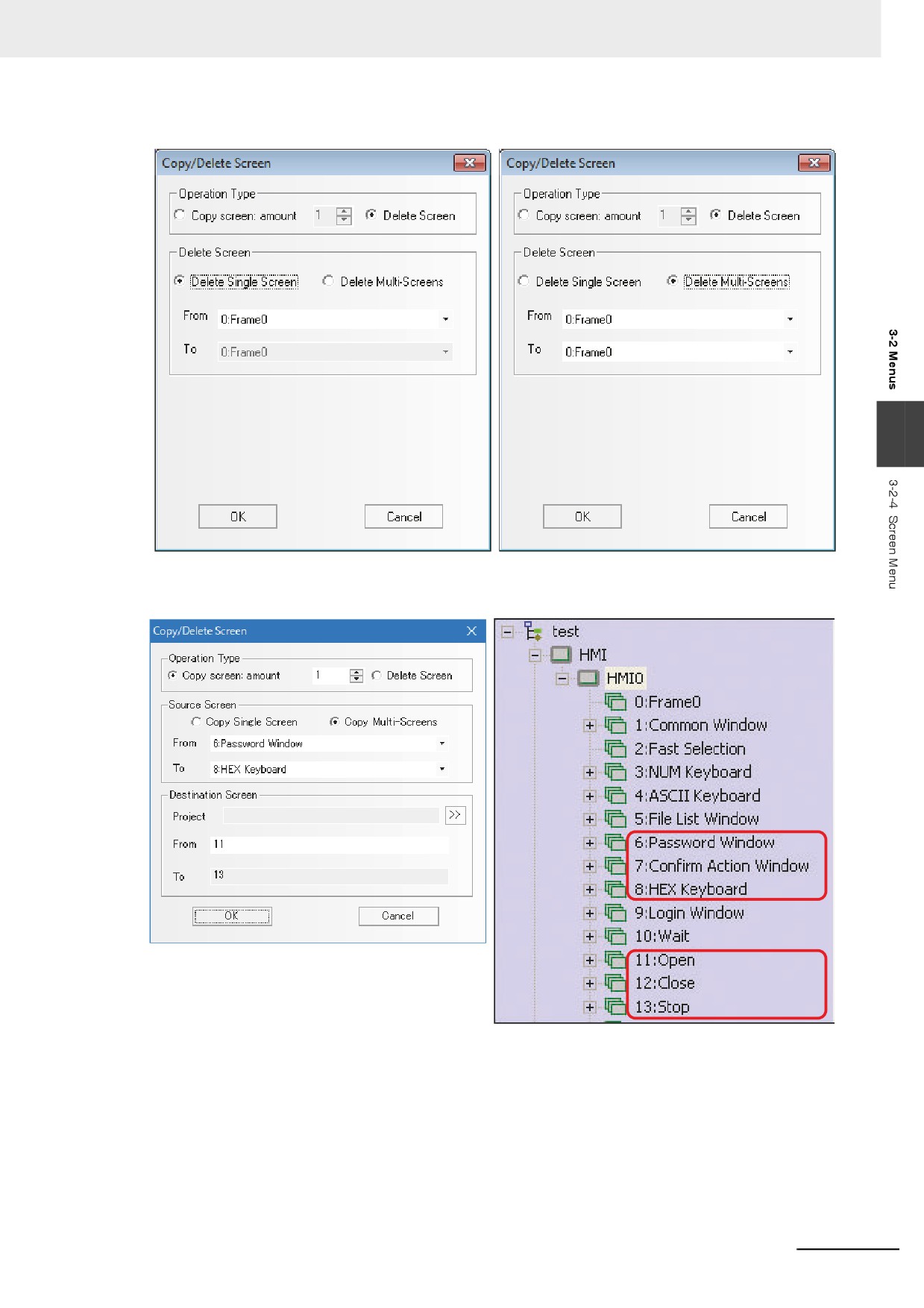
(2) Delete Screen
Supports single-screen deletion or multiple-screen deletion.
• Delete Single Screen
The starting screen ID can be set, which means to delete the screen with this ID.
• Delete Multi-Screens
Both the starting screen ID and the end screen ID can be set, which means to delete the screens
with the ID between the starting ID and the end ID.
3-28
3 Functions of NB-Designer
3
The following example is only for the multiple-screen copying.
We want to copy Frame 6, Frame 7 and Frame 8 into Frame 11, Frame 12, and Frame 13.
Note 1
The copy of screens is available within the same project or the same PT.
2
When the multiple screens are operated, the copying and deletion among the non-continuous screens are
not supported.
3-29
3 Functions of NB-Designer
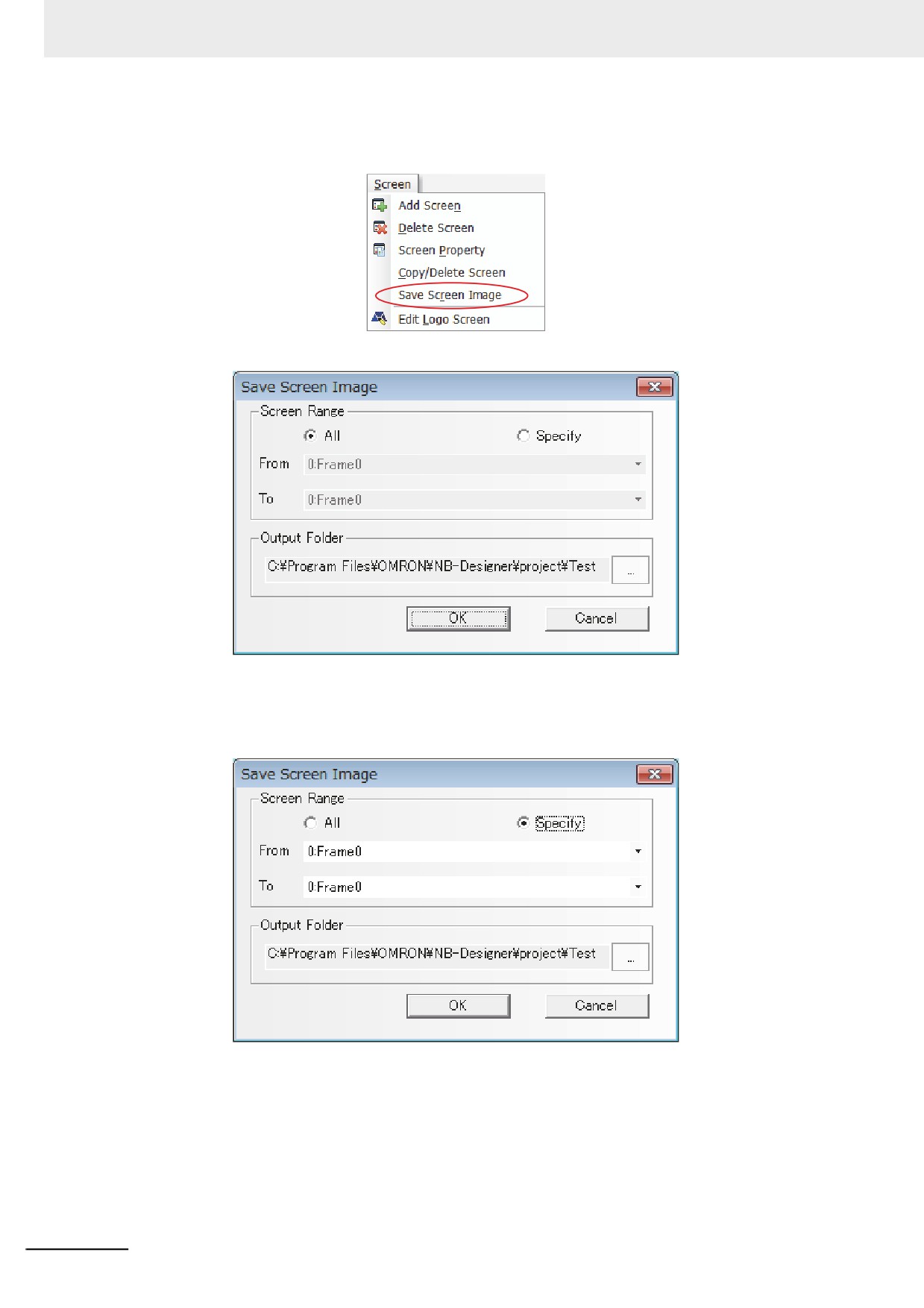
z Save Screen Image
Select a project data and open a screen to enable this function.
Click [Screen] - [Save Screen Image] , then the dialog box below appears to save the screen images.
z Screen Range
Specify the screen area to save to a file. Select [All] to save all screens. Click [Specify], then the field
[From] and [To] are enabled. Specify the range to save.
z Output Folder
Designate a folder to save the file. The folder where the project data is stored is specified by default.
A screen image data is saved as bitmap file to the designated folder.
3-30
3 Functions of NB-Designer
3-2-5
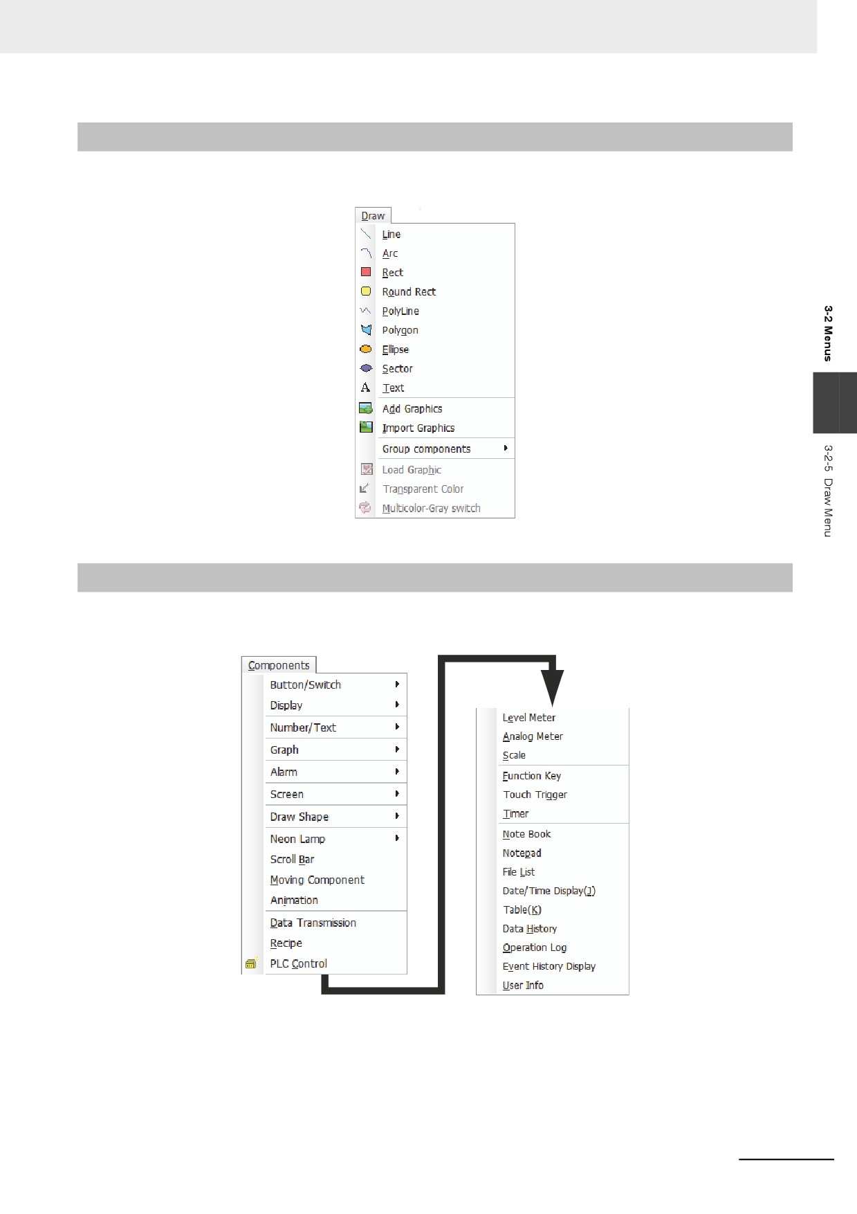
Draw Menu
The corresponding contents in the [Draw] menu shown as below have been described in 3-2-3 View
Menu (Page 3-16).
3
3-2-6
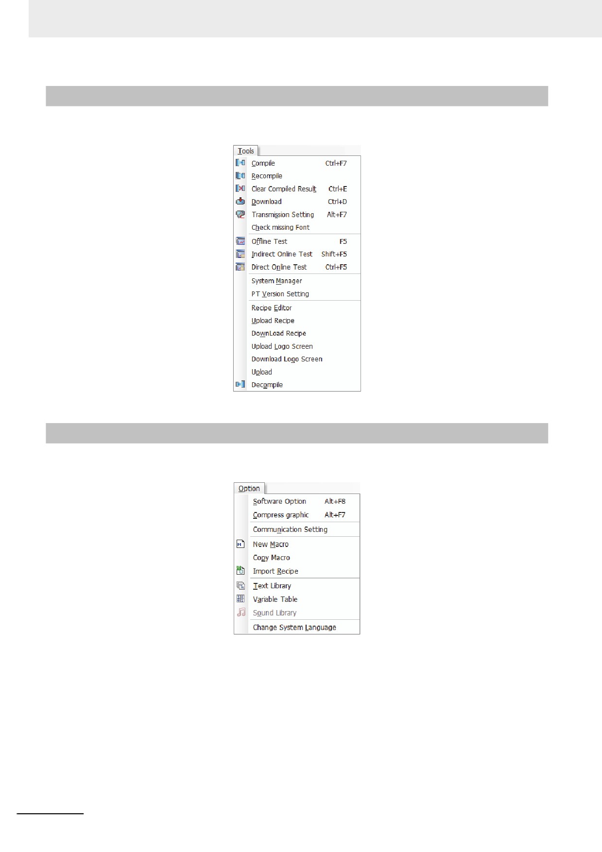
Components Menu
For the corresponding contents in the [Components] menu shown as below, refer to 3-6 Parts (Page 3-
82), 3-7 Function Parts (Page 3-200) and 3-8 Project Database (Page 3-238).
3-31
3 Functions of NB-Designer
3-2-7
Tools Menu
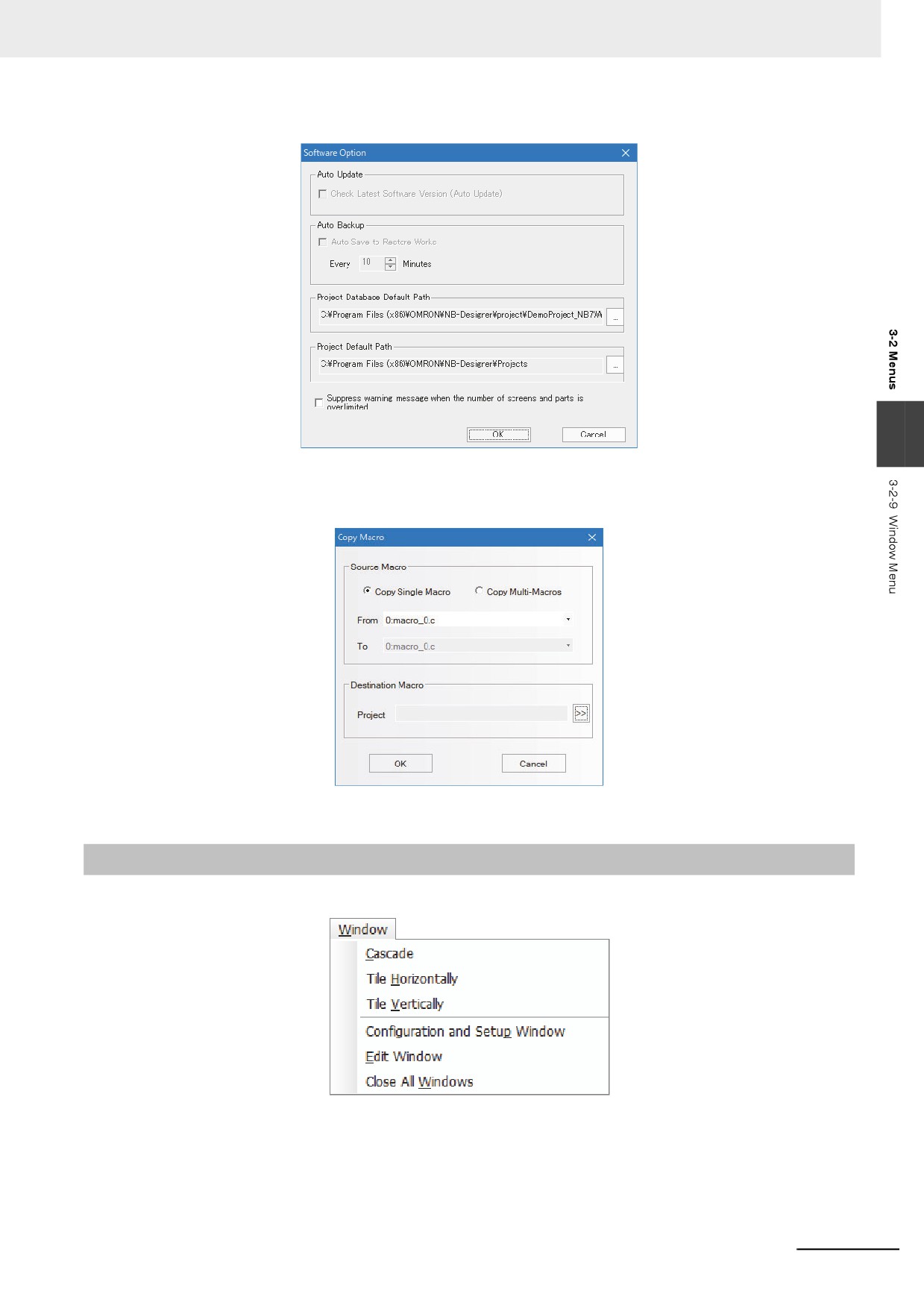
For the corresponding contents in the [Tools] menu shown as below, refer to 3-12 Recipe Data (Page
3-343), 3-14 Test (Page 3-360) and 3-15 Download (Page 3-363).
3-2-8
Option Menu
The corresponding contents in [Option] menu shown as below have been described in 3-2-3 View
Menu (Page 3-16).
3-32
3 Functions of NB-Designer
Software option: Sets operation of NB-Designer.
3
Copy Macro: Macros can be copied and pasted to other project. Copied macros are pasted to the
destination project given the macro numbers which begin with the next number of the last macro
number.
Change System Language: used for changing the system language of the software tool.
3-2-9
Window Menu
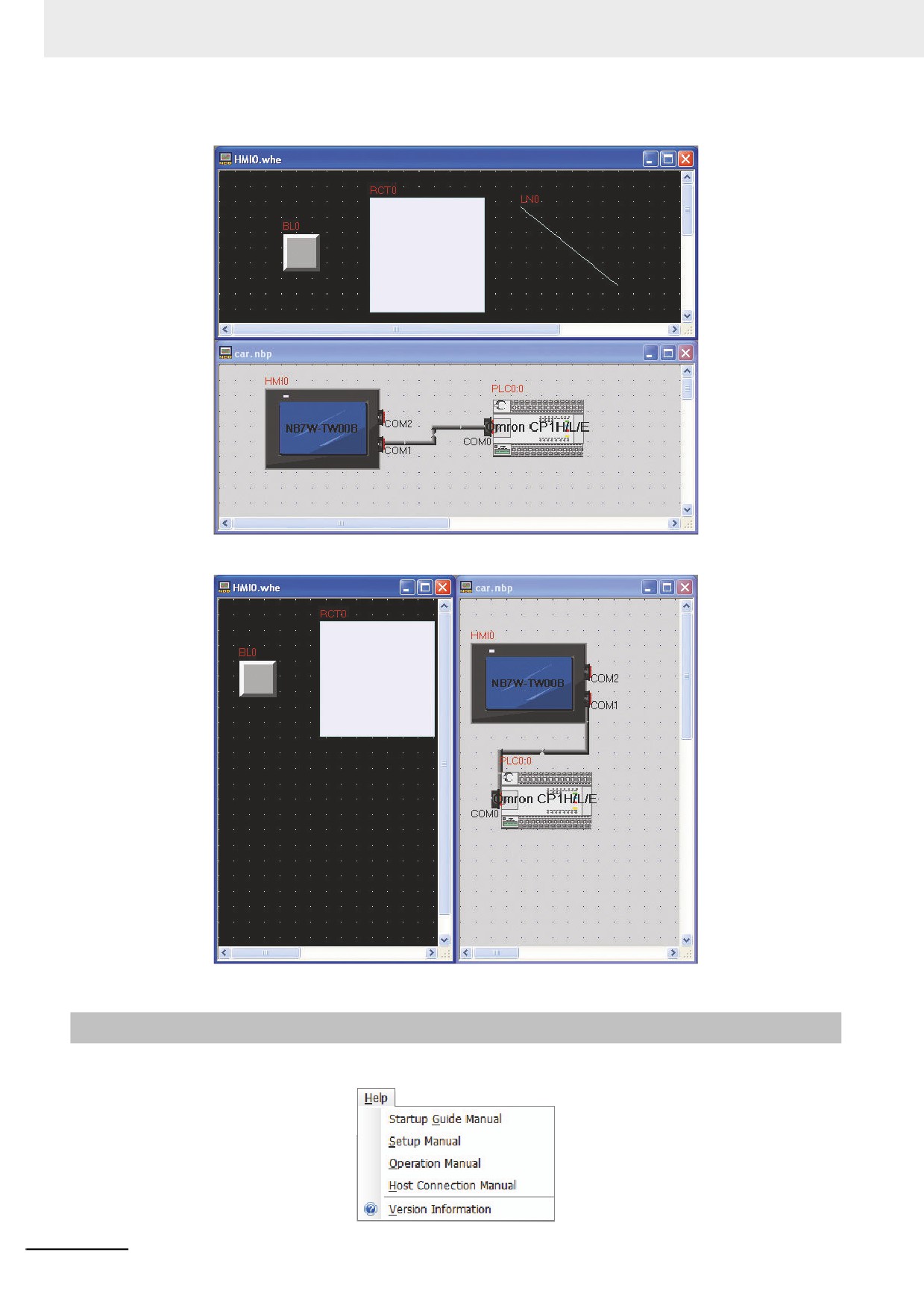
The corresponding contents in the [Window] menu are as follows.
3-33
3 Functions of NB-Designer
The horizontally-tile window is shown as below.
The vertically-tile window is shown as below.
3-2-10
Help Menu
The corresponding items in the [Help] menu are shown as follows.
3-34
3 Functions of NB-Designer
3-3
NB-Designer Software Window
NB-Designer has quite a few windows, which will be illustrated in this part.
3-3-1
Project Library Window
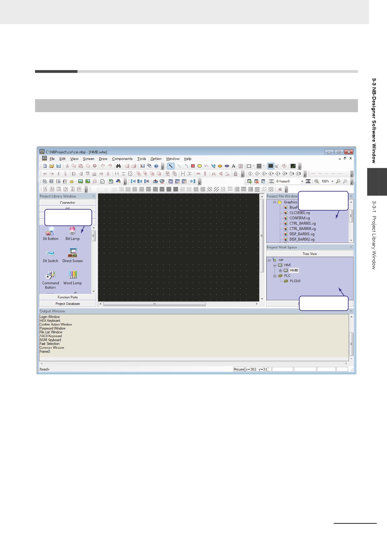
When starting the NB-Designer, you will see Project Library Window, Project File Window, and Project
Work Space shown as below. For the concept of the “screen”, the brief will be provided in 3-4 Screen
Concept (Page 3-47).
3
Project File Window
Project Library Window
Project Work Space
The Project Library Window contains: Connector, PT, PLC, Parts, Function Parts and Project
Database.
Connector: Serial Port, Ethernet
PT: NB3Q-TW00B, NB3Q-TW01B, NB5Q-TW00B, NB5Q-TW01B...
PLC: OMRON, SIEMENS, MITSUBISHI, Schneider…
Parts: Bit Button, Bit Switch, Word Lamp, Data Log, XY Graph, Number Input, Text Input…
Function Parts: Scale, Function Key, Alarm Display, Timer…
Project Database: Text Library, Variable Table, PLC Control…
3-35
3 Functions of NB-Designer
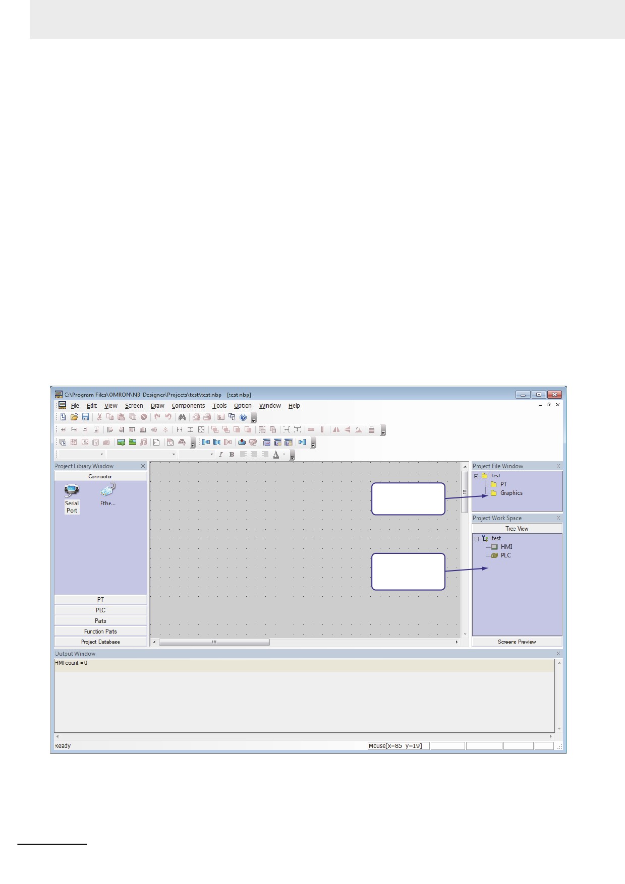
Directions:
1
Connector
Just click “Serial Port”, and drag it to the Project Work Space.
2
PT
Check your PT type, find and drag the PT with the same type in the “PT” to the Project Work
Space.
3
PLC
Check your PLC type, find and drag the PLC with the same type in the “PLC” to the Project
Work Space.
After finishing selection of the PLC, PT and Connector, carry out connection. The connection
method is as follows: move the locations of PT and PLC accordingly, or click one end of the
connection line and drag it to the vicinity of the COM port of the PLC or the PT, then bring the
connection port close to either end of the connection line, and a successful connection can be
completed.
Note If the PLC or PT is not dragged into the “Project Work Space”, both of the “Project File Window” and “Project
Work Space” will be empty, as shown below.
PT and Graphics
are empty
PT and PLC
is empty
3-36
3 Functions of NB-Designer
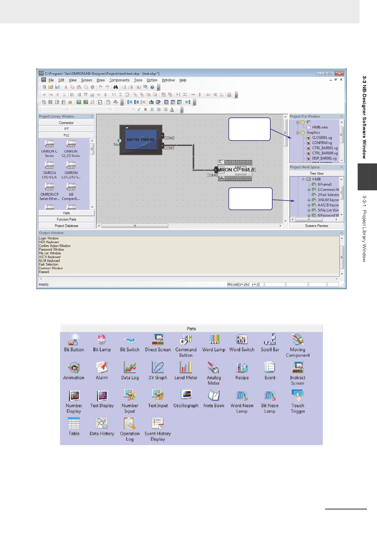
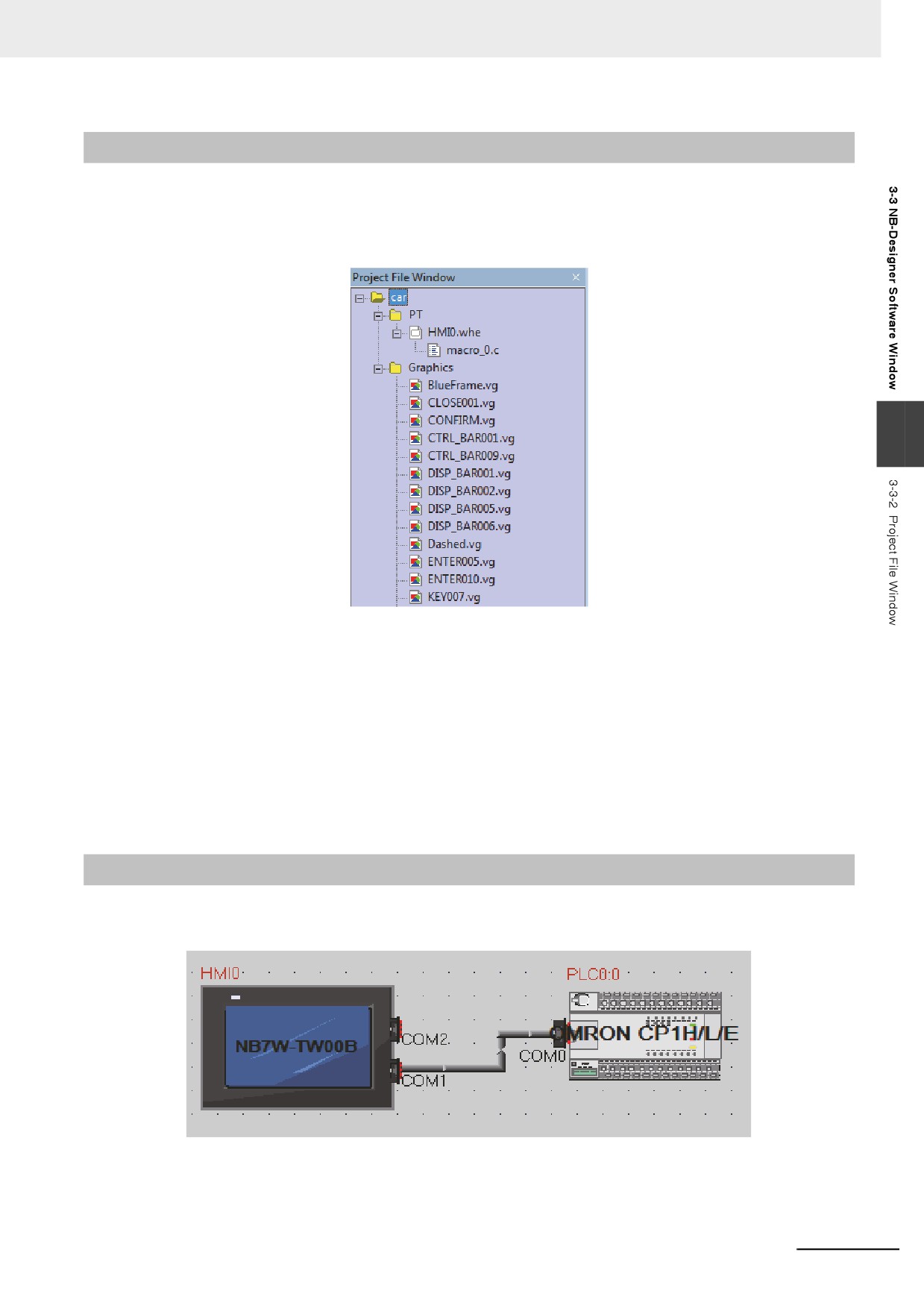
Once the PLC and PT are dragged in, the “Project File Window” and “Project Work Space” will
be filled with appropriate content, as shown below:
PT with appropriate
contents
3
PT and PLC with
appropriate contents
4
Parts
These include various editing components, as shown below:
When a project is created, and the Edit Window is entered, it just needs to drag the required
components to the Edit Window.
As to the usage methods of the components, refer to 3-6 Parts (Page 3-82).
3-37
3 Functions of NB-Designer
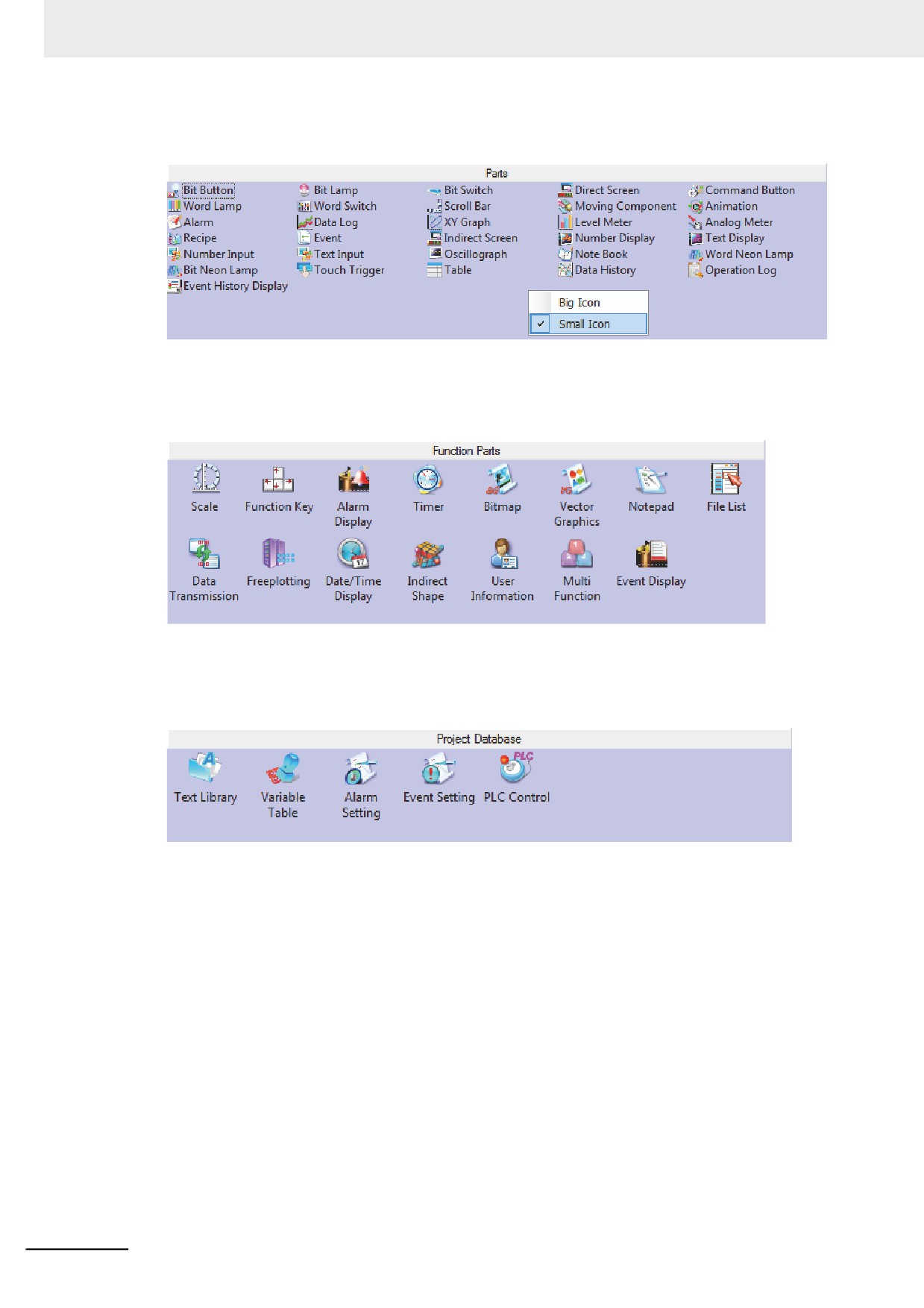
In the Project Library Window, you can right-click, select and use “Small Icon”, as shown
below.
5
Function Parts
These include Scale, Function Key, Alarm Display, Timer, etc. For details, refer to 3-7 Function
Parts (Page 3-200).
6
Project Database
This contains Text Library, Variable Table, Alarm Information, Event Information and PLC
Control. For details, refer to 3-8 Project Database (Page 3-238).
3-38
3 Functions of NB-Designer
3-3-2
Project File Window
The Project File Window is intended for displaying information about the PT, Macro, Recipe and Vector
Graphic, etc. contained in a project. If this project uses 1 PT, only one “HMI0.whe” will appear below the
[PT]. if 3 PTs are involved, “HMI0.whe, HMI1.whe, HMI2.whe” will appear accordingly. The rest can be
deducted from this. See the following diagram.
3
By clicking the “+” or “-” symbol on the left of the icon, the folder tree can be unfolded or folded.
By double-clicking a specific file, the editing state can be entered.
Note The recipe file (.RCP) can only be imported and deleted, but not be edited in the Edit Window.
Graphics
The Graphics mainly indicates this project contains how many Vector Graphics and bitmaps. If a new
Vector Graphics or bitmap is created in this project, it will show up immediately here. If a created Vector
Graphics or bitmap is double-clicked, the screen will be switched to the graphics edit window
immediately. For Vector Graphics and bitmaps, refer to 3-5-5 Vector Graphic (Page 3-60) and 3-5-6
Bitmap (Page 3-65).
3-3-3
Project Work Space
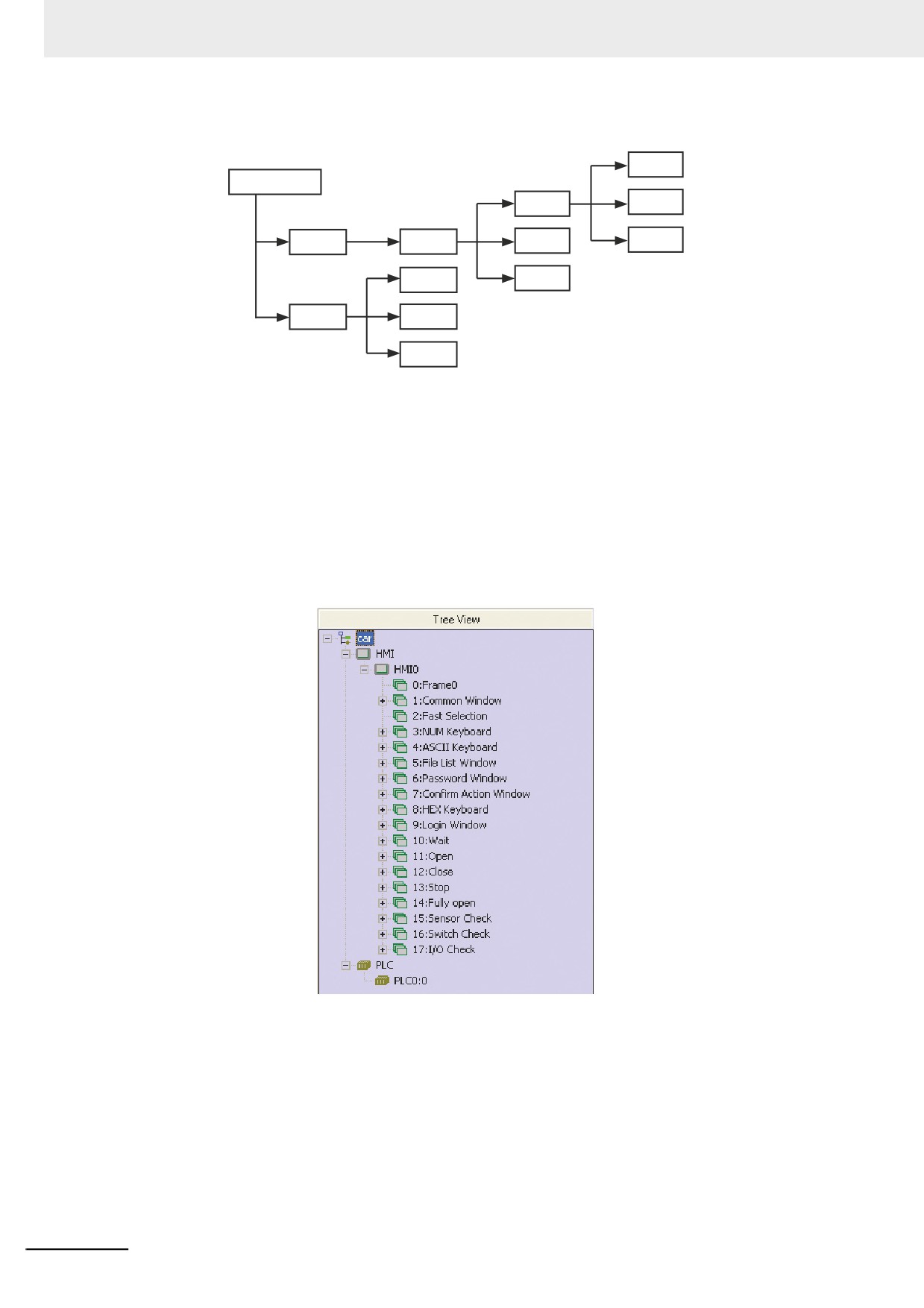
The Project Work Space is mainly intended for displaying the structure of the project, and contains two
parts: PT and PLC, as shown below.
3-39
3 Functions of NB-Designer
And the schematic diagram is shown as below.
Part 0
Project Name
Screen 0
Part 1
HMI
HMI 0
Screen 1
Part n
PLC 0
Screen n
PLC
PLC 1
PLC n
z PT
It mainly displays (stores) the PT used in the project, each of which also has a subfolder. Every
folder stores its own structure.
z PLC
It mainly displays (stores) the number of PLC, PLC No. and Station No. addresses used in the
project.
Note Creating a new project for each PT is recommended.
z Tree View
All the components contained in each screen will be displayed here, and if there is no component in
a screen, nothing will appear below it.
By clicking the “+” or “-” symbol on the left of icon, the folder tree can be unfolded or folded. Directly
double-click the Screen or the component No. in the Screen to skip to the edit page involving the
component. When a Screen or component is selected, pressing the DELETE button can delete the
related screen or component.
3-40
3 Functions of NB-Designer
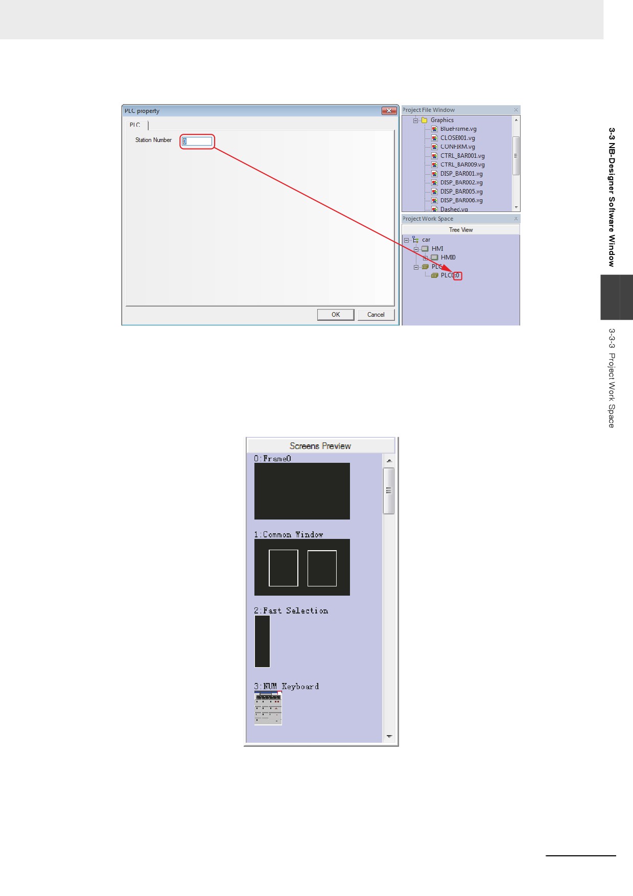
Explanation about the characters on the top of the PLC Property window.
3
The first digit indicates the PLC No. currently used.
The second digit indicates the Station No. of PLC currently used.
z Screens Preview
Click [Screens Preview] in the [Project Work Space] to display the preview of the corresponding
screen. This makes browsing the thumbnails quite conveniently.
z PLC and PT replacement
• Supporting PLC Model Replacement
Note PLC replacement must be carried out through the [Change PLC Model] option. If you do not use this
function and delete all the settings of PLC to reconnect with the new PLC, the PLC area is replaced with
all the local addresses of PT.
3-41
3 Functions of NB-Designer
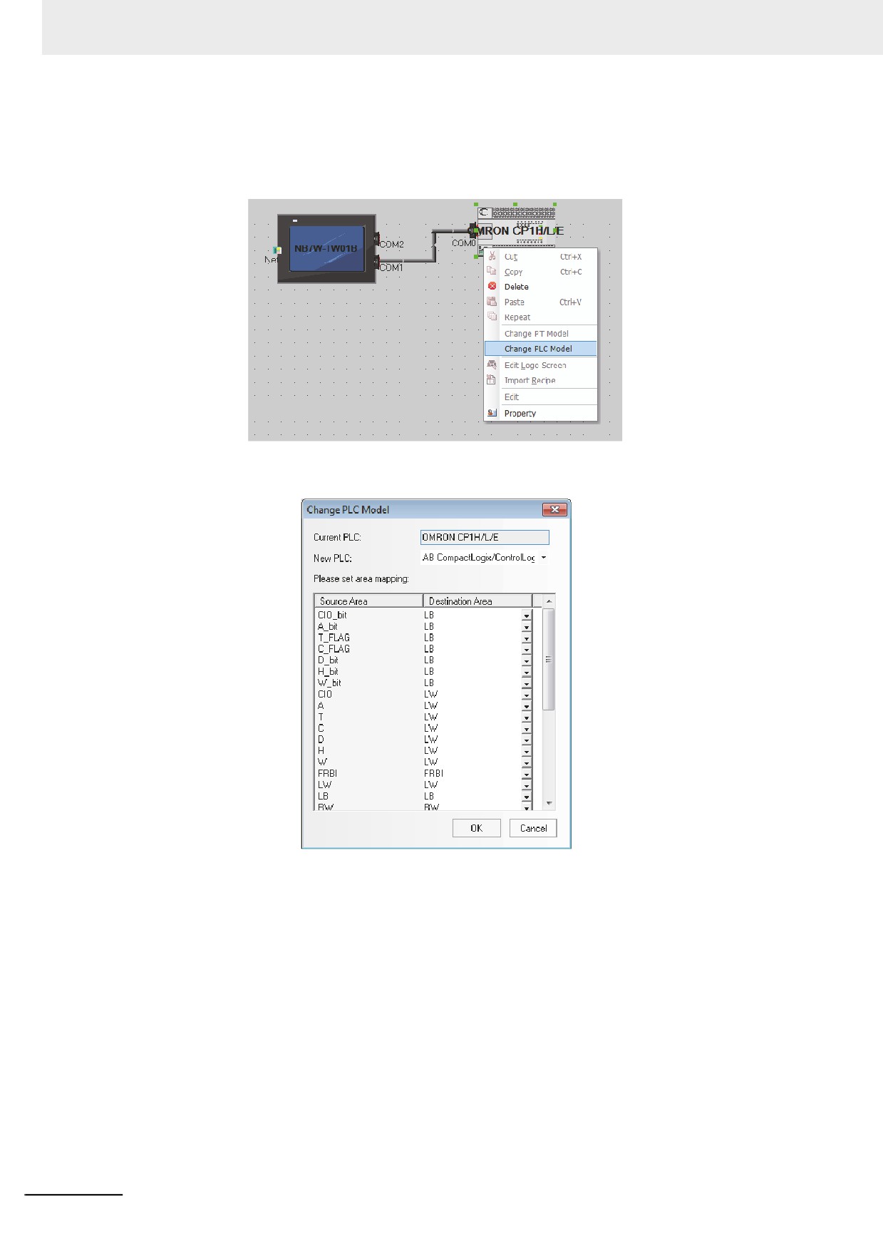
It provides a parameter setting dialog box for the PLC to be replaced and other PLCs in the
navigation mode for the user to make replacement operation. Select a PLC and right-click it in the
Configuration and Setup Window to make the pull-down menu popup, and then click “Change PLC
Model”.
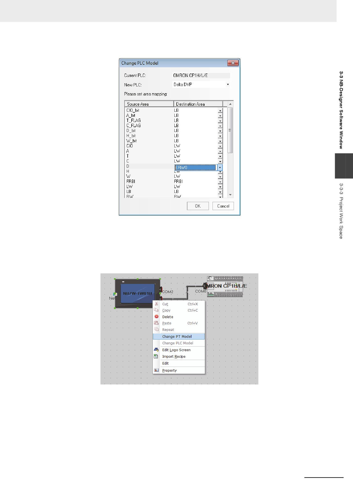
Then, the Change PLC Model dialog box will pop up, as shown below.
A dialog box as shown above will pop up automatically, and all the supported PLC names are
included in the pull-down list of the PLC names. When the user select a PLC, the memory address
types supported by this PLC will be added to the address type box. The default selections are LB &
LW, but the user can select different address types according to the specific PLC. After being
confirmed by the user, the PLC will be replaced, and the corresponding PLC memory address in the
project will also be replaced at the same time.
Note The function does not support the replacement from the unit type of the Ethernet connections to the unit type
of the serial connections.
3-42
3 Functions of NB-Designer
An example of setting addresses for [Current PLC] and [New PLC] are as follows.
3
• Supporting PT Model Replacement
Note PT replacement must be carried out through the [Change PT Model] option. If you do not use this
function and delete all the settings of PLC to reconnect with the new PLC, the PLC area is replaced with
all the local addresses of PT.
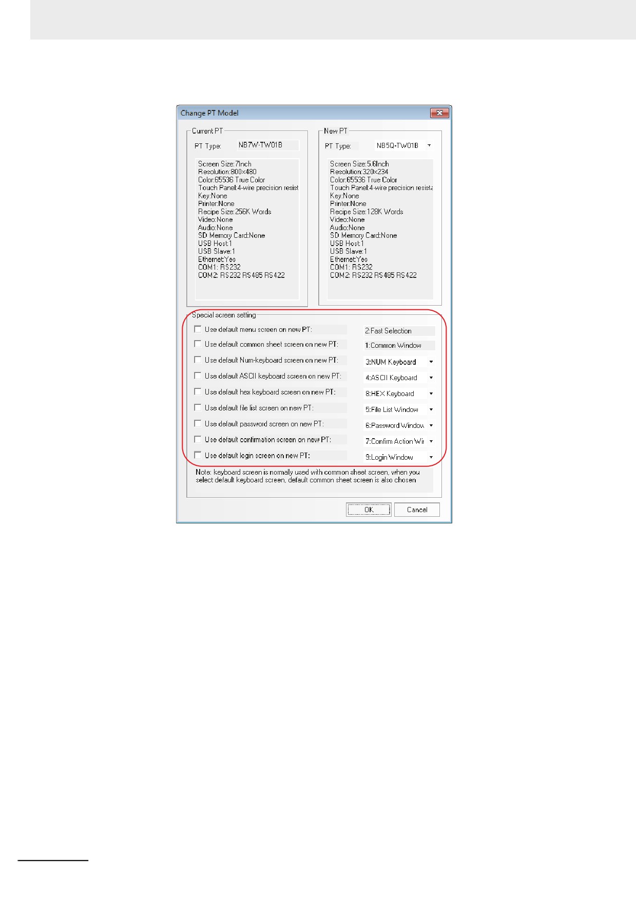
When the PT needs to be replaced, you can select the PT by right-clicking it in the Configuration
and Setup Window, and select “Change PT Model” in the pop-up menu.
3-43
3 Functions of NB-Designer
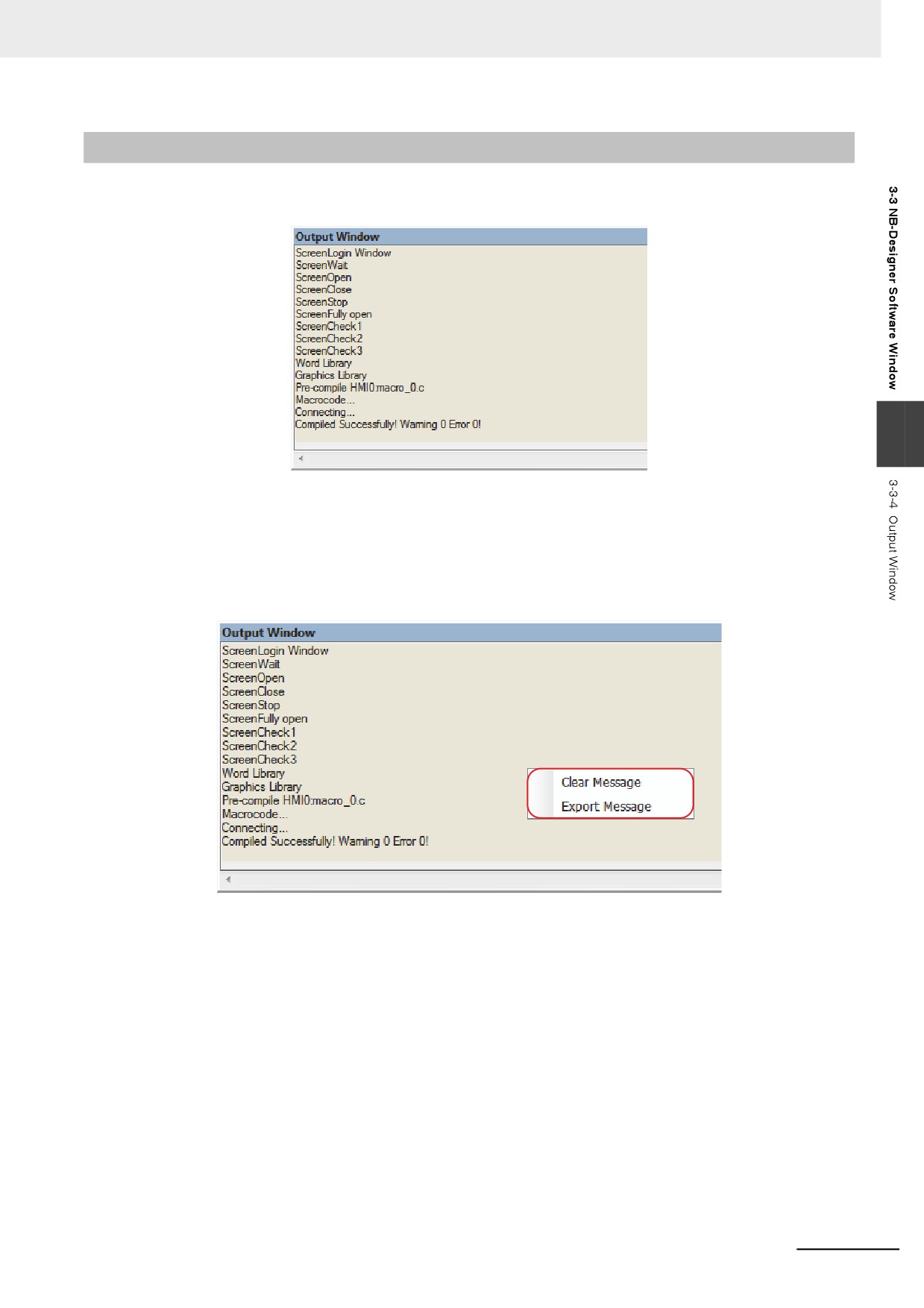
The following dialog box will pop up automatically.
Here, the name and descriptions of the Current PT cannot be altered, while the pull-down box of the
New PT lists all the supported [PT type], and the descriptions displayed at the lower part will be
updated automatically according to the type selected by the user. After being confirmed, the PT will be
replaced, and all the size of graphics in the PT will zoom automatically according to the resolution of the
screen.
After the PT is replaced, the original user edit screen will be adjusted by related scales according to the
difference of the resolution of various types. All the components with screen display will adjust
automatically. For example, all the components (such as the bitmaps, Vector Graphics, button and
lamp, etc.) with location and size adjustments can all change their sizes automatically. However, note
that there are a few exceptions: as the font size of text strings and label can’t be changed, the
components using text strings and label will be restricted to mainly display the text in the minimum
display area when size changes, especially when it becomes smaller as square components like the
Analog Meter change sizes in a “square” way, the changed sizes may disrupt the proportion among the
component sizes, therefore it requires a second fine-adjustment by the user.
By the [Special screen settings] in the dialog box, the special screen which will be replaced to Replace
PT is set. If the [Special screen settings] is not used, the special screen of the Current PT will continue
to be used.
If the resolutions of the Current PT and New PT are the same, no adjustment is required. But on the
contrary, if they are different, it will require the user to adjust the fonts and pictures to appropriate sizes.
3-44
3 Functions of NB-Designer
3-3-4
Output Window
The Output Window mainly displays compilation information of the project so that the user can precisely
pinpoint where errors lie, as shown below.
3
When the project is opened, the Output Window will display the loaded information of the project. when
the project is compiled, the Output Window will display the compilation process and error information.
z Clearance/Export of Message
The compiled information can be cleared or exported in the Output Window. Right-click the mouse
in the [Output Window], the following menu will pop up.
Clear Message: All the information in the Output Window will be removed.
Export Message: All the contents in the Output Window are exported to the folder which contains
the current project, forming a file named “log.txt”.
3-45
3 Functions of NB-Designer
3-3-5
Component List Window
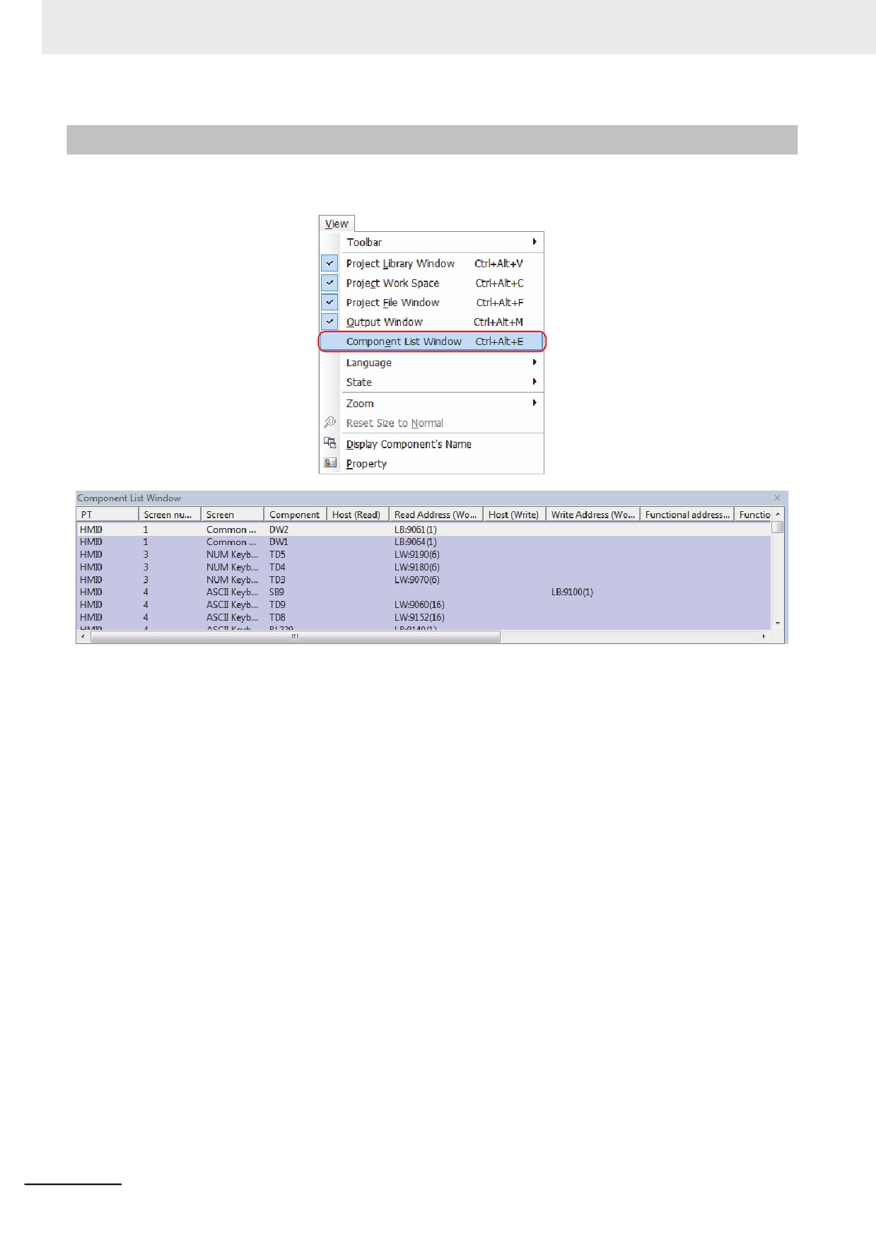
If the [Component List Window] is selected from the [View] menu, the Component list window will pop
up.
This window displays all the component information used by the project, including PT No., Screen,
Component's Name, Read PLC, Read Address, Write Address, Functional Address etc. Double-click
an item to reveal the Properties of the selected component, and the Edit Window will skip to the screen
where this component locates.
3-46
3 Functions of NB-Designer
3-4
Screen Concept
3-4-1
Screen Types
The project of the NB-Designer is composed of multiple screens. There are 3 types of screen, i.e. Base
Screen, Common Sheet and Menu Screen. The Base Screen after its size is changed can also be used
as Pop-up Screen. All the screen can be used as the Sheet Screen.
z
Base Screen
This is the common-type screen. When Base Screen is switched by using “Screen switching”
command, the current screen will be cleared (All the screen rather than Common Sheet and Menu
Screen will be cleared.), and Base Screen to be switched to will be displayed in the current screen.
When the component in Base Screen calls the pop-up screens out, the original information in Base
3
Screen will be reserved, and the called pop-up screen will be attached to the current Base Screen.
The master-slave relationship is between Base Screen and all of related pop-up screens. When
Base Screen N is switched to Base Screen M, all of the sub-screens of Base Screen N will be
closed while Base Screen M and its sub-screens will be displayed. Base Screen must cover the
whole screen.
z
Menu Screen
Menu Screen is the screen called by pressing the button of Menu Screen while the task-bar is
displayed, and it will be always displayed in the screen until the operation button makes it hidden.
Therefore, it can be used to put screen-switching button or some other common components. The
default Menu Screen is Frame 2. When the other screen is set as Menu Screen, the size of that
screen must be same as that of Menu Screen.
z
Common Sheet
Common Sheet will always be displayed in the screen, and the components to be displayed forever
can be put in Common Sheet. In this way, you can see the state of this component or operate this
component at any time. The default Common Sheet is Frame 1. You can use [Change Common
Sheet] function key to switch the other screen as the current Common Sheet, but only one screen
can be used as the current Common Sheet.
z
Sheet Screen
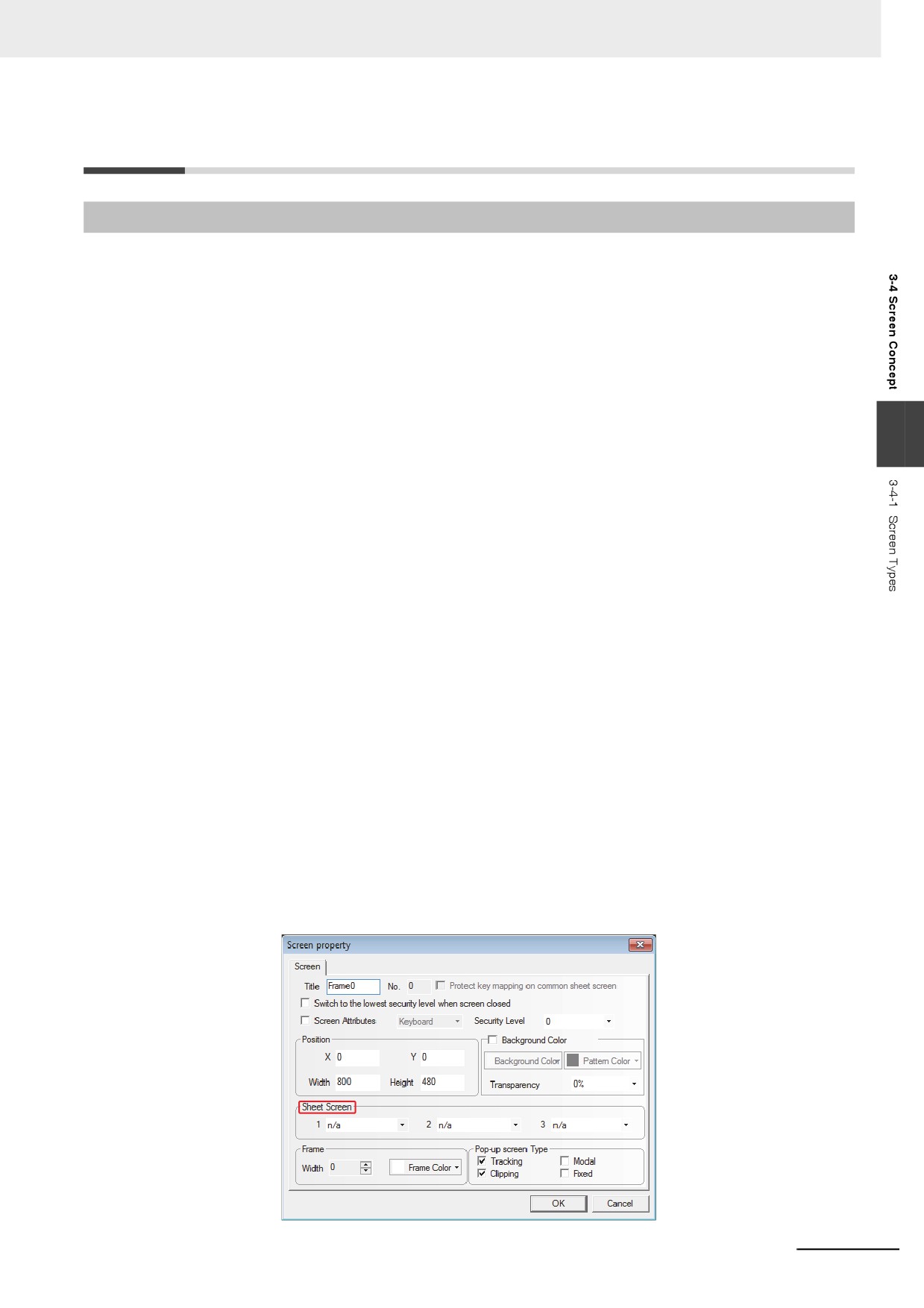
3 Sheet Screens (max.) can be set for the screen in [Screen Property] dialog box. Sheet Screen is
generally used to put some common components such as background graphics, charts and titles
and so on for the multiple components. Each screen can be set as Sheet Screen.
3-47
3 Functions of NB-Designer
As shown above, Sheet Screen can be selected directly from the [Sheet Screen] option. Sheet
Screen is different from the general screen. The components in Sheet Screen will be inserted into
the general screen during the running, and in fact Sheet Screen isn’t displayed at all, but the display
and control of its components are similar to that of the components in the general screen.
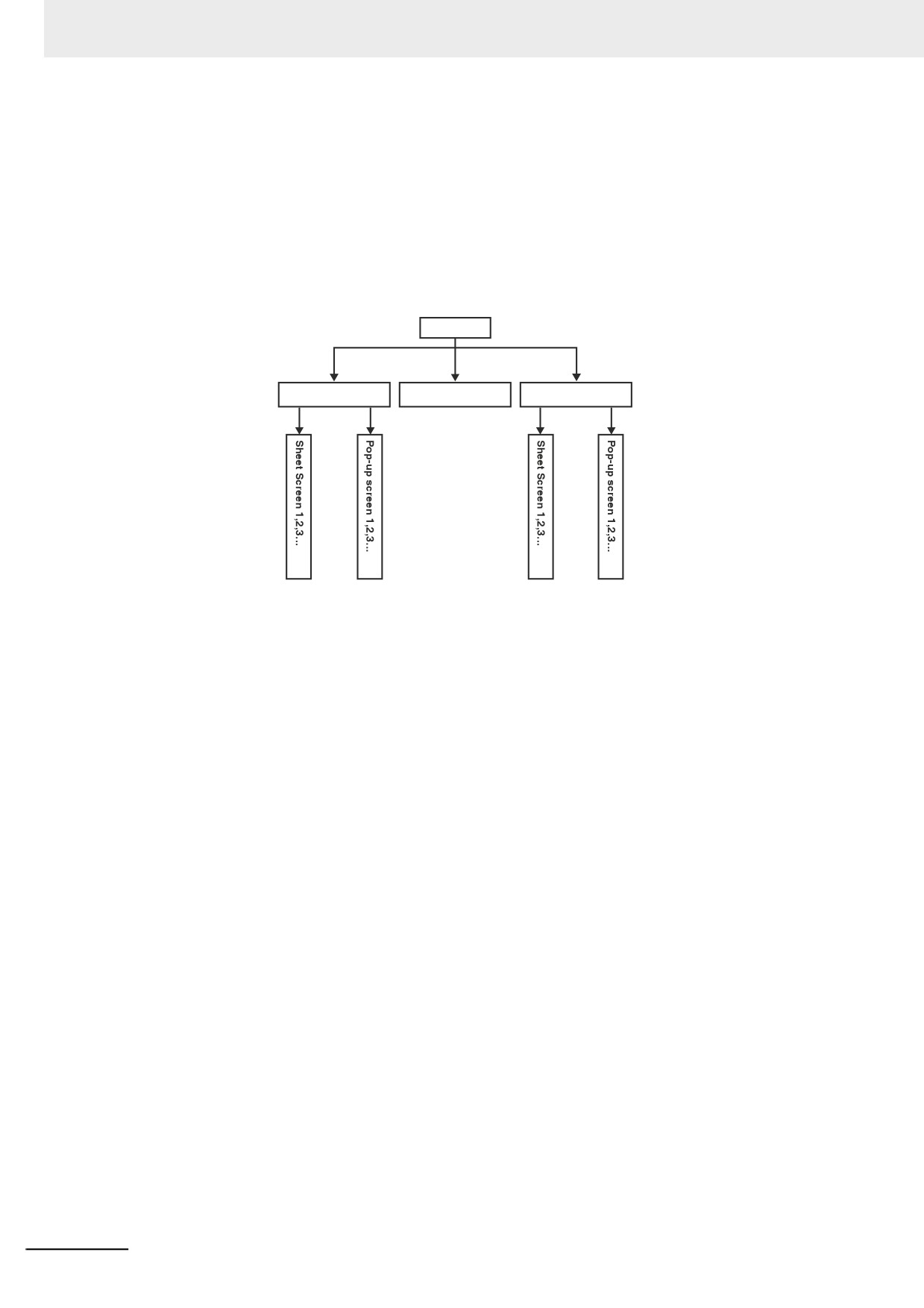
z The Relationship of Screen
One screen can include Common Sheet, Base Screen and Menu Screen while one Common Sheet
or Base Screen can include many pop-up screens. And the relationship between them is shown as
below.
Screen
Base Screen
Menu Screen
Common Sheet
When the screen-switching command is executed, the PT will clear the current screen (the pop-up
screen attached on the current screen etc included) and switch to the screen to be displayed, but
Common Sheet will always be displayed in the screen. The original contents of Base Screen can’t
be changed by the pop-up screen that called by the direct screen or indirect screen, and the pop-up
screen is just attached to Base Screen. In addition, up to 3 sheet screens can be set for each screen
in screen property setup.
When one Base Screen (Screen No. is 0 or ranges from 10 to 32767) is called out, all the
components in this screen will be displayed in the PT. If Base Screen has the Sheet Screen, all the
components defined in its Sheet Screen will be displayed. All of the Touch Trigger components
(such as Bit Button, Function Key etc.) defined in the Sheet Screen are valid in the current screen. If
there are display components in Common Sheet, they will be displayed in the current screen. And
all the Touch Trigger components defined in Common Sheet are valid.
Each project includes 32768 screens (max.) (Base Screen, Common Sheet and Menu Screen etc
included), and only one screen can be used as Menu Screen. But you can use [Change Menu
Screen] function key to make the screen switch to the specified screen as Menu Screen. For details,
refer to 3-7-2 Function Key (Page 3-201).
Each new project has a default initial screen, and the default screen No. is 0 (If you want to change
it, you just need to make changes in [PT Property] in project editing screen.). The valid screen No.
ranges from 0 to 32767.
3-48
3 Functions of NB-Designer
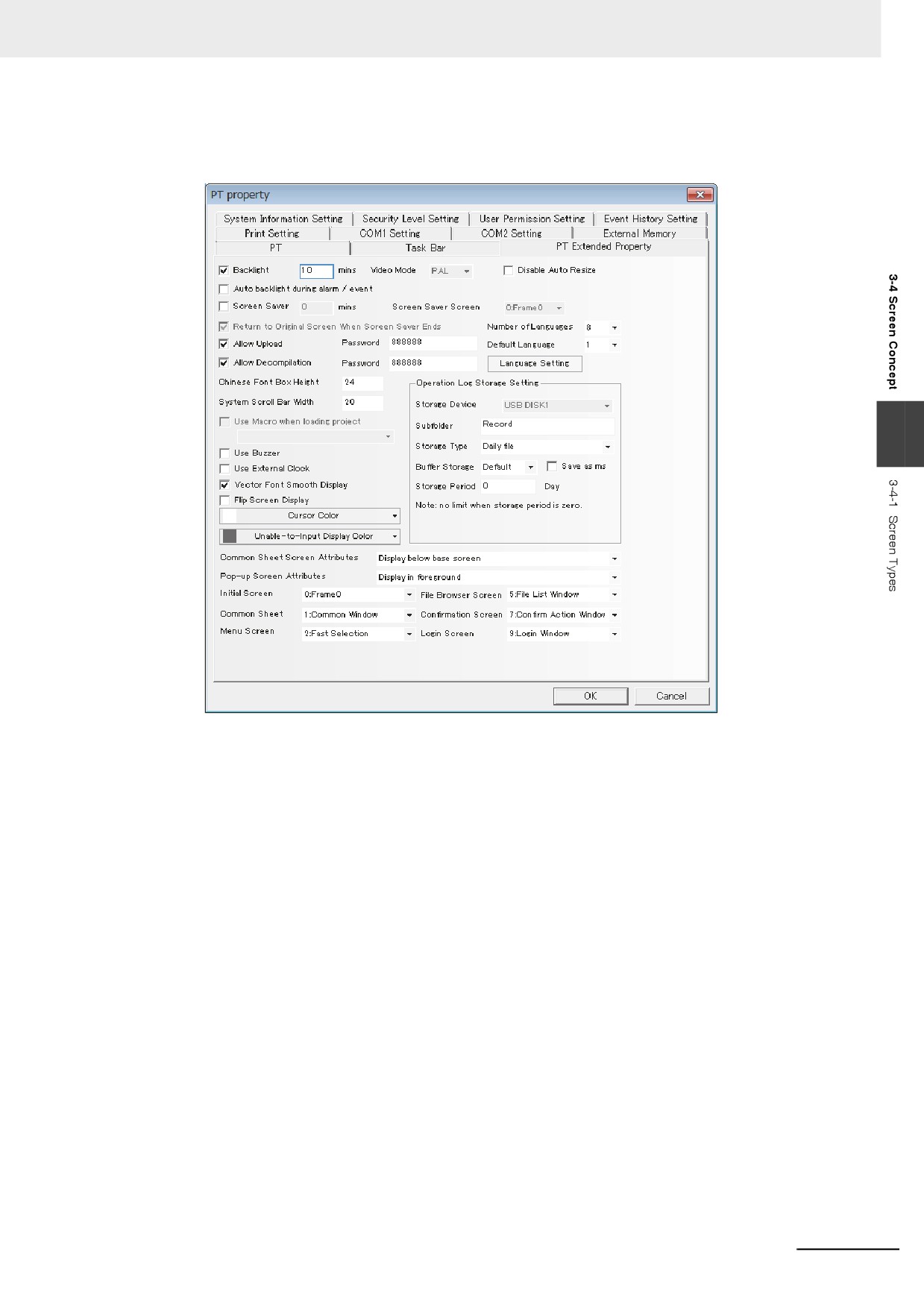
The default Common Sheet and Menu Screen for the project are Frame 1 and Frame 2. If you want to
change the default Menu Screen and Common Sheet, you just need to double click PT to modify [PT
Extended Property], as shown below:
3
Note 1
16 pop-up screens can be opened simultaneously.
2
More than two of the same screens cannot be called from one screen simultaneously.
Therefore you can’t open the same screen by using 2 direct (indirect) screens in the Base Screen.
3
The screens closed by the function keys can’t close the Direct Screen or Indirect Screen, because the
opening or closing of Direct Screen is related to the ON/OFF status of bit address that controls the Direct
Screen, while the opening and closing of Indirect Screen is just related to the data content of the word
address that controls the Indirect screen. The screen closed by the function keys can’t change the values
of these bits (words) addresses, so it can’t close these screens mentioned above.
4
All the Pop-up Screens are attached to the current Base Screen, so when the current screen is closed (or
switched to the other Base Screen), the attached Pop-up Screen will be closed. In this case, if the screen
is switched back to this Base Screen, you will find that the Pop-up Screens originally attached to this Base
Screen still exist (Otherwise there are commands sent to close them.)
5
Base Screen must cover the whole screen.
6
Every Pop-up Screen belongs to the screen where the component ejecting them locates, and master-
slave relationship is between them. Therefore, the screen opened by the component in Common Sheet
will always be displayed until Common Sheet closes it again.
3-49
3 Functions of NB-Designer
3-4-2
Screen Property
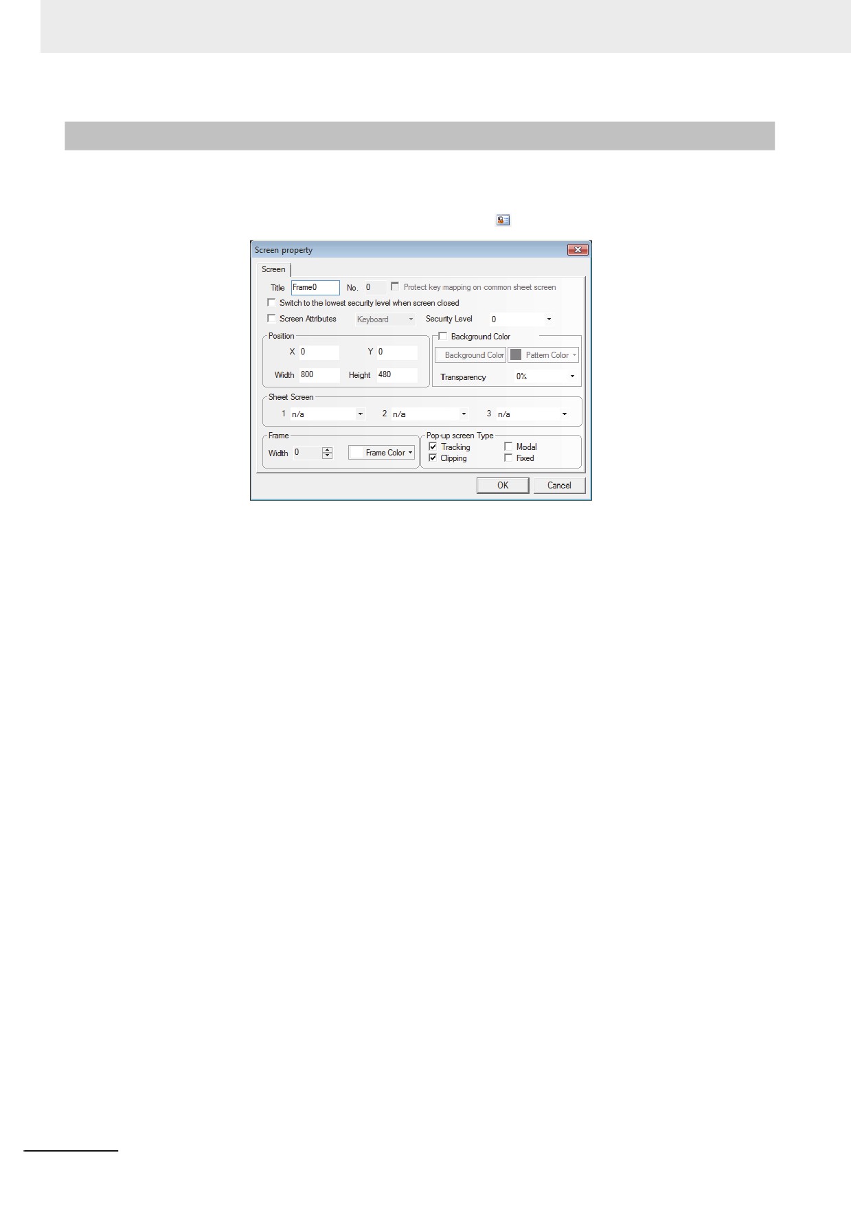
The methods to change the screen property:
• Double-click the area in which no components are arranged in the screen.
• Do not click the components in the screen and click the
icons of tool bar.
z
Title
Assign the unique name for each screen for convenient differentiation. Of course, the screen title
can be changed.
z
Screen No.
Screen No. range is from 0 to 32767. When a new screen is created, automatically is assigned a
Screen No.
Screens from 0 to 10 are fixed. The screen No. of the other screens can be changed by the user.
Screen No. can be not consecutive.
z
Position
When the screen is the screen ejected by using “Pop-up Screen” function of the function key, the
vertex in the upper-left of the screen will be displayed in this position.
z
Width and Height
Width and height can be set for the Pop-up Screen, and if it is the Base Screen, it must be set to the
default size (i.e. the size of the full screen).
z
Screen Attribute
Keyboard page determines whether to set the screen as Keyboard Screen. Print page can be used
to set the size of this screen regardless of the limitation of the actual resolution of the PT. The NB
Series does not support [Print page].
z
Protect key mapping on common sheet screen
The NB Series does not support this function.
z
Switching to the lowest security level when screen closed
If the security level is set for one screen to realize the function, i.e. the password will be cleared
automatically when the screen is closed, and the password needs to be input again when the screen
is entered again, the security level will become 0 only if the screen is closed.
3-50
3 Functions of NB-Designer
z Background Color
If the filling effects for the screen are needed, select this option.
z Pattern Color and Background Color
The selected [Pattern Color] is applied as outline color and the selected [Background Color] is
applied as ground color. (For details, refer to the descriptions of “Fill Style Toolbar” in 3-2-3 View
Menu (Page 3-16)). In the default settings, the [Pattern style] is set to 0 so that only the background
color is displayed by this setting.
z Pop-up Screen Type
The types are “Tracking”, “Modal”, “Clipping” and “Fixed”.
The above parameters show the relationship between one Pop-up Screen and its adjacent screen.
If one Pop-up Screen features “Modal”, the location of parent screen will be frozen after it pops up,
and the pop-up screen will always be displayed in the Top layer. If one Pop-up Screen features
3
“Clipping”, the border of this screen will be restricted by its parent screen, i.e. the part displayed out
of the border of its parent screen will be cut off. If one Pop-up Screen features “Tracking”, it will
move together when its parent screen moves.
Note If “Clipping” is selected, “Tracking” must be selected simultaneously.
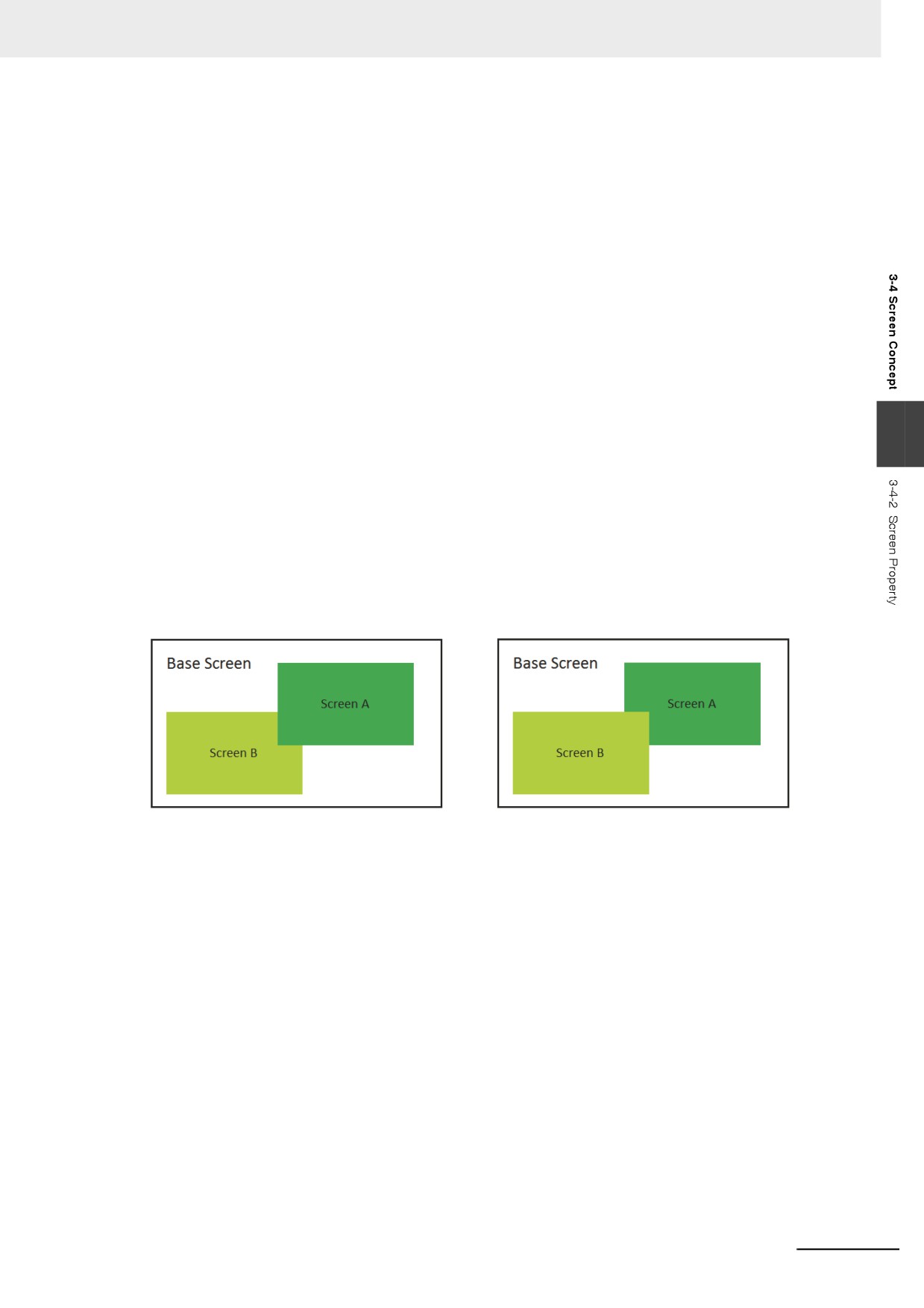
The following Screen A and Screen B are both attached to the Base Screen. Generally, Screen A
will be displayed in the Top layer when it is touched. But if “Fixed” is selected for Screen A, it will not
be displayed in the Top layer even if it is touched, but it will always be attached to its parent screen.
Note The screen No. can’t be changed once it is created, but the name, frame and background can be changed
still.
z Security Level
Set the corresponding security level for the screen. For details, refer to 3-13 Security Level (Page 3-
354).
z Sheet Screen
Set the corresponding Sheet Screens for the current screen. The screen to be set as the Sheet
Screen must be the created screen, where the components used by the multiple screens together
can be put.
z Frame
Refers to the frame recommended to be used by the Pop-up Screen. The width of the frame can be
any number from 0 to 16. If the width is not 0, the color can be selected for the frame.
3-51
3 Functions of NB-Designer
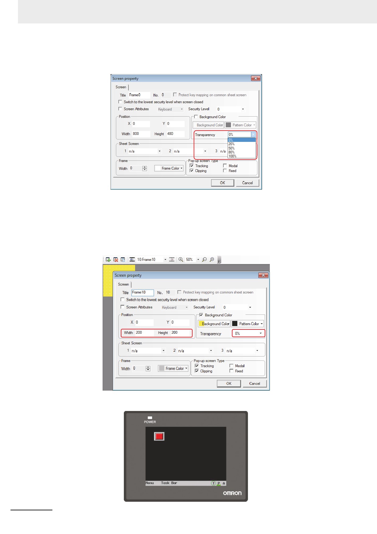
z Transparency
It is only valid for the Pop-up Screen and the Menu Screen.
Example of transparency of Pop-up Screen
Placing one function key to [Pop-up screen] “Frame 10” with the property in “Frame 0”, as shown
below.
• When the transparency is 0%.
Set the width and height of Frame 10 to “200” each, the [Background color] to “Yellow”, and the
[Transparency] to “0%”, as shown below.
Perform the offline test, as shown below.
3-52