OMRON NB-Designer OPERATION MANUAL (NB-series, 2020) - page 2
Installation and Startup of NB-
2
Designer
The NB-Designer software needs to be installed on your computer when you use it for
the first time.
NB-Designer is a kind of application software running in Windows developed by
Microsoft Corporation.
2-1
Before Installation
2-2
2-2
Installation/Uninstallation
2-3
2-2-1
Installation Procedure
2-3
2-2-2
Uninstallation Procedure
2-3
2-3
Startup & Quit
2-4
2-3-1
Starting Method
2-4
2-3-2
Quitting Method
2-4
2-4
Installation of USB Driver for NB
2-5
2-1
2 Installation and Startup of NB-Designer
2-1
Before Installation
The system environment to run the NB-Designer is as follows.
System Configuration
Items
Minimum Configurations
Operating System (OS)
Microsoft Windows XP (SP3 or higher)
Microsoft Windows Vista (32-bit or 64-bit edition)
Microsoft Windows 7 (32-bit or 64-bit edition)
Microsoft Windows 8 (32-bit or 64-bit edition)
Microsoft Windows 8.1 (32-bit or 64-bit edition)
Microsoft Windows 10 (32-bit or 64-bit edition)
CPU
Intel Pentium II or higher
Memory
512 MB or more
Hard Disk
2.5 GB or more, with the disk space more than 800 MB at least
Display
Supports the display with resolution of 800×600 and 16-bit high color
(1024×768 and 32-bit true color are recommended.) .
100% (96DPI) is recommended for Windows Text size (DPI) settings.
RS-232C COM Port
One port or more is kept for the serial communication used by the
touch panel.
USB Port
USB 1.1 or higher
CD-ROM Drive
4x or higher
2-2
2 Installation and Startup of NB-Designer
2-2
Installation/Uninstallation
2-2-1
Installation Procedure
1
Start Windows.
2
Double click [Setup_NBD_V ] to perform the installation.
Note For download the application programs, please access your local OMRON website. If local site
2
cannot be found, please access OMRON IA global site “http://www.ia.omron.com/” at first and select
the area where you are.
3
Select your language to use the program in the [Choose Installation Language] window, and
click NEXT.
4
Click the [Next] again to display the [Select the Destination Location] dialog box.
5
After selecting default of the installing location, click the [Next].
6
To select another available location to install, click [Browse]. After a folder list appears, select an
available folder to install NB-Designer. Then click the [OK] and followed by [Next].
7
When [Ready to install the program] dialog box appears, click [Install] to start installation.
8
When [InstallShield Wizard is completed] dialog box appears, click [Finish] to complete the
installation.
9
Start NB-Designer on Windows other than Windows XP.
If you use NB-Designer on Windows other than Windows XP, NB-Designer is executed with
administrator authority.
2-2-2
Uninstallation Procedure
Perform [Uninstall or change a program] in Windows.
Note When using new-version software to update a project created with software of an old version, backup
necessarily the project before update.
Precautions for Correct Use
In order to use the product correctly, when running the software, do not perform definitely
update, restoration, uninstallation, and reinstallation.
2-3
2 Installation and Startup of NB-Designer
2-3
Startup & Quit
This section provides a brief for startup and quit of NB-Designer.
2-3-1
Starting Method
Select [Start]-[All Programs]-[OMRON]-[NB-Designer]-[NB-Designer]. The startup can also be realized
by double clicking the shortcut icon
on the desktop.
• The user should run this program as an administrator in operation system of Windows other than
Windows XP.
• When the NB-Designer is started for the second time, the project operated last time will be opened
automatically.
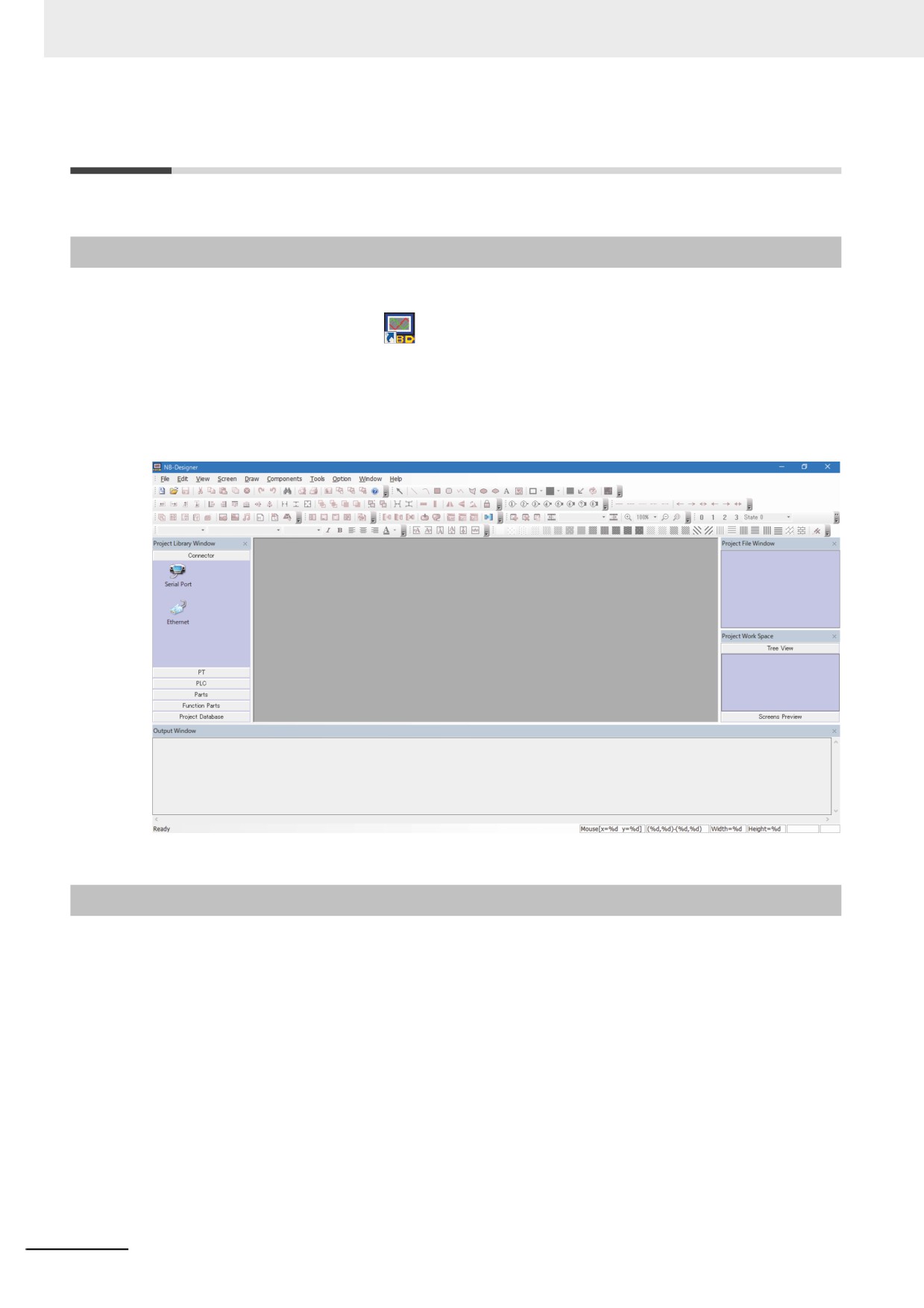
• During the first launch of NB-Designer, the following screen will be displayed.
2-3-2
Quitting Method
To quit the NB-Designer can be realized by using any one of the following methods.
• Select [Exit] in the [File] menu.
• Click the button in the upper right corner of the main window.
• Double click the NB-Designer icon in the upper left corner of the main window.
• Click the NB-Designer icon in the upper left corner of the main window, and select [Close] from the
displayed control menu bar.
• Press the [Alt] key and [F4] key simultaneously.
Note When the edited data in the file is not saved, “Save the Current Project?” dialog box will pop up.
2-4
2 Installation and Startup of NB-Designer
2-4
Installation of USB Driver for NB
Install the USB driver for NB on PC.
After the installation, the data transmission between the PC and the NB Unit is available via USB.
Because the USB driver included in the NB-Designer is certified by Microsoft, it will be installed
automatically accompanying with the software installation, so there is no need to install the USB driver
by manual again.
z Operating procedure
2
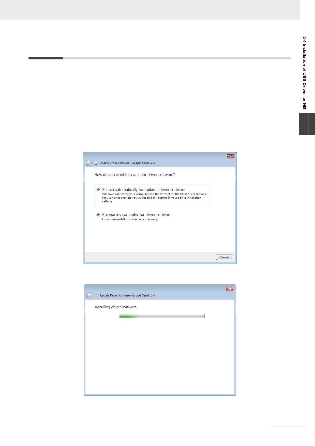
1 After the USB slave for the NB Unit and the computer are connected by the USB cable, “Found
New Hardware Wizard” will be displayed on PC. After selecting [Install the software
automatically (Recommended)], click the [Next] button.
2 USB driver is being installed.
2-5
2 Installation and Startup of NB-Designer
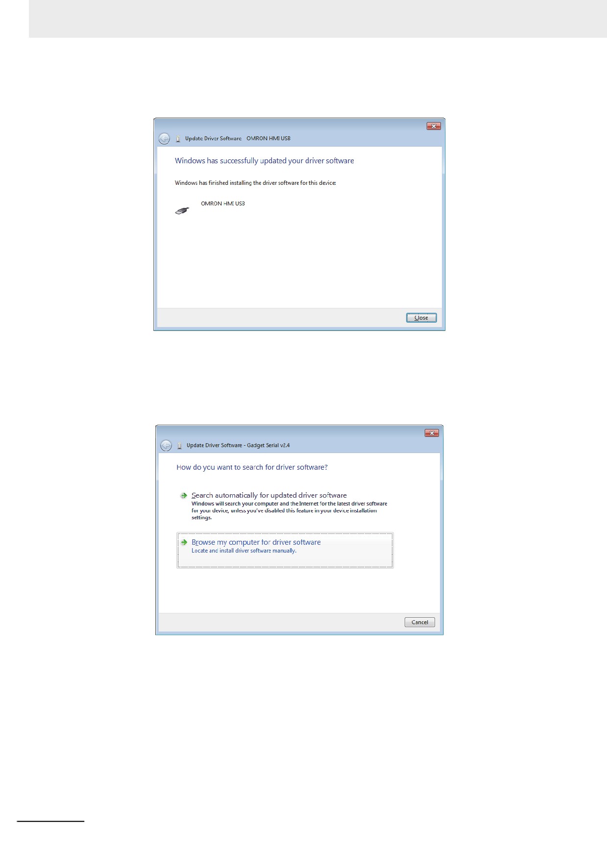
3 After the completion of installation, the following dialog box will be displayed. Click the [Close]
button.
z When the above-mentioned installation methods don’t work.
1 After the USB slave for the NB Unit and the computer are connected by the USB cable, “Update
Driver Software” will be displayed on PC. After selecting [Browse my computer for driver
software].
2-6
2 Installation and Startup of NB-Designer
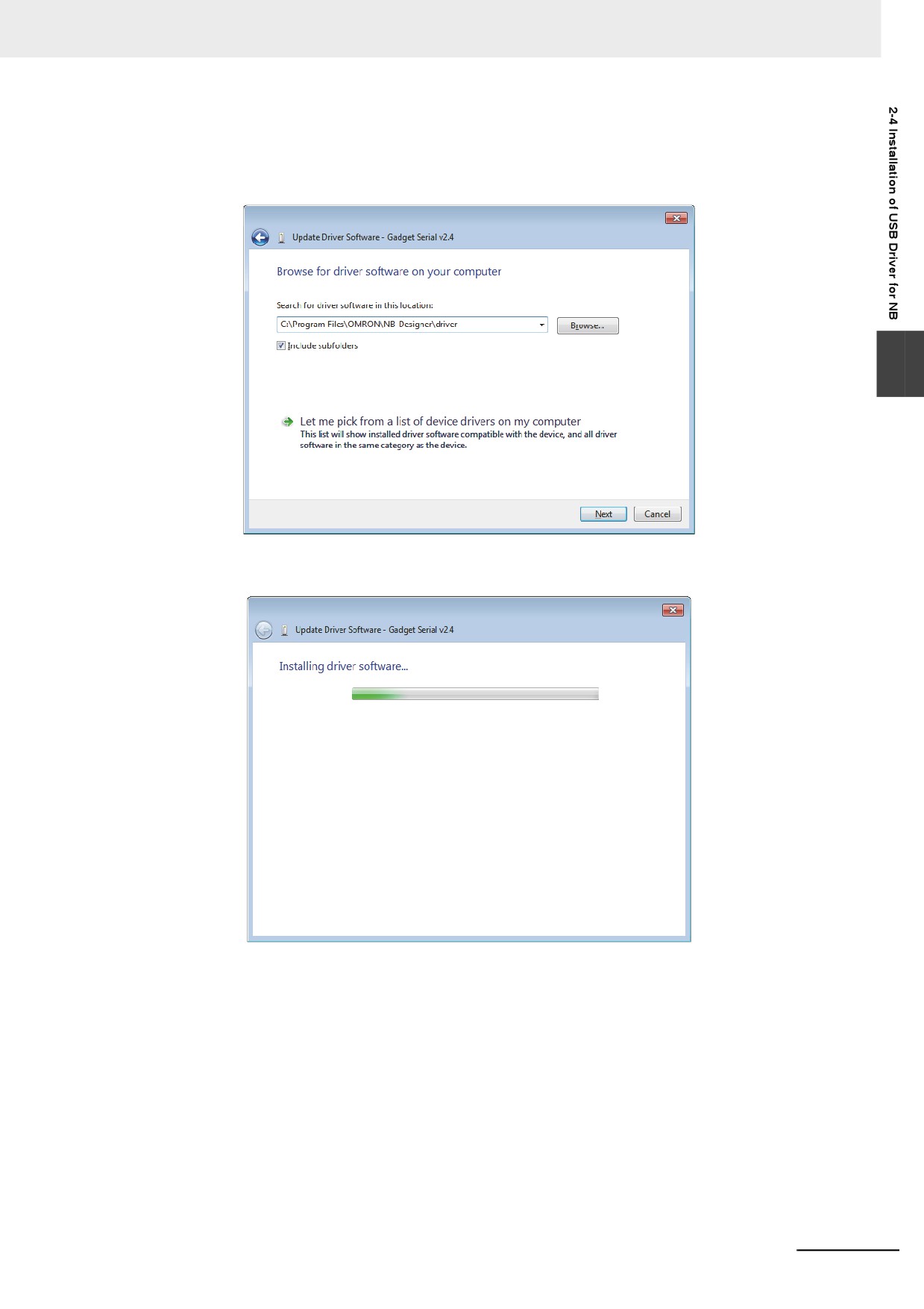
2 The following dialog box is displayed. Select [Include subfolders] and click the [Browse] button
to specify the folder.
Specify the driver folder under NB-Designer installation directly and click [Next] button.
2
3 USB driver is being installed.
2-7
2 Installation and Startup of NB-Designer
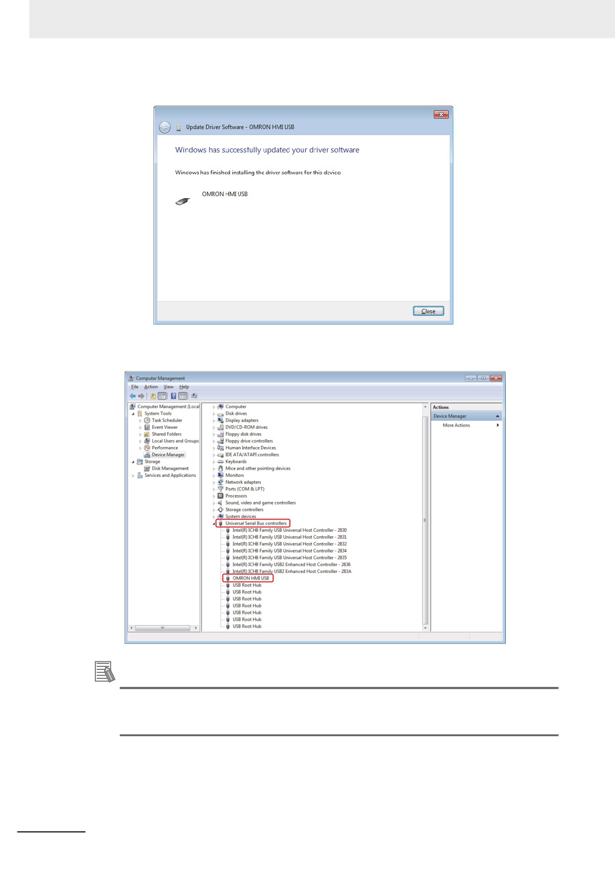
4 After the completion of installation, the following dialog box will appear. Click the [Close] button.
You can check whether the USB driver is installed successfully by selecting “Computer /
Manage / Hardware / Device Manager / Universal Serial Bus controllers” location, as shown
below.
Additional Information
When USB device is registered as Gadget Serial, it may not be installed automatically. In this
case, right-click on the device manager, and select Update Driver Software from the menu, then
take this step.
2-8
Functions of NB-Designer
3
This section describes the functions of NB-Designer.
3-1
User Screen
3-4
3-2
Menus
3-7
3-2-1
File Menu
3-7
3-2-2
Edit Menu
3-11
3-2-3
View Menu
3-16
3-2-4
Screen Menu
3-27
3-2-5
Draw Menu
3-31
3-2-6
Components Menu
3-31
3-2-7
Tools Menu
3-32
3-2-8
Option Menu
3-32
3-2-9
Window Menu
3-33
3-2-10
Help Menu
3-34
3-3
NB-Designer Software Window
3-35
3-3-1
Project Library Window
3-35
3-3-2
Project File Window
3-39
3-3-3
Project Work Space
3-39
3-3-4
Output Window
3-45
3-3-5
Component List Window
3-46
3-4
Screen Concept
3-47
3-4-1
Screen Types
3-47
3-4-2
Screen Property
3-50
3-4-3
Screen Creation
3-54
3-4-4
Screen Opening
3-54
3-4-5
Screen Deletion
3-55
3-4-6
Components Related to Screen
3-55
3-5
Basic Design Method
3-56
3-5-1
Designing Components
3-56
3-5-2
About ID No
3-57
3-5-3
Additional Comments (Descriptions)
3-58
3-5-4
Read/Write Address for PLC
3-59
3-5-5
Vector Graphic
3-60
3-5-6
Bitmap
3-65
3-5-7
Creating Label
3-68
3-1
3 Functions of NB-Designer
3-5-8
Task Bar and Operation Buttons
3-70
3-5-9
Fonts
3-72
3-5-10
Basic Properties of Component
. . . . 3-75
3-5-11
Control Setting of Component
3-76
3-5-12
Display Setting of Component
3-80
3-6
Parts
3-82
3-6-1
Bit Button
3-82
3-6-2
Bit Lamp
3-85
3-6-3
Bit Switch
3-88
3-6-4
Command Button
3-89
3-6-5
Word Lamp
3-96
3-6-6
Word Switch
3-98
3-6-7
XY Graph
3-102
3-6-8
Moving Component
3-111
3-6-9
Animation
3-116
3-6-10
Number Input
3-118
3-6-11
Number Display
3-124
3-6-12
Text Input
3-127
3-6-13
Text Display
3-131
3-6-14
Level Meter
3-132
3-6-15
Analog Meter
3-143
3-6-16
Indirect Screen
3-147
3-6-17
Direct Screen
3-150
3-6-18
Alarm
3-152
3-6-19
Data Log
3-154
3-6-20
Recipe
3-164
3-6-21
Oscillograph
3-164
3-6-22
Scroll Bar
3-168
3-6-23
Event
3-171
3-6-24
Note Book
3-178
3-6-25
Word Neon Lamp
. . . 3-189
3-6-26
Bit Neon Lamp
3-190
3-6-27
Touch Trigger
3-191
3-6-28
Table
3-193
3-6-29
Data History
3-194
3-7
Function Parts
3-200
3-7-1
Scale
3-200
3-7-2
Function Key
3-201
3-7-3
Alarm Display
3-209
3-7-4
Timer
3-213
3-7-5
Bitmap
3-218
3-7-6
Vector Graphics
3-219
3-7-7
Notepad
3-220
3-7-8
Data Transmission
. . . 3-223
3-7-9
Freeplotting
3-226
3-7-10
Date/Time
3-227
3-7-11
Indirect Shape
3-229
3-7-12
User Information
3-233
3-7-13
Multifunction
3-233
3-7-14
Event Display
3-236
3-2
3 Functions of NB-Designer
3-8
Project Database
3-238
3-8-1
Text Library
3-238
3-8-2
Variable Table
3-244
3-8-3
Alarm Setting
3-248
3-8-4
Event Setting
3-253
3-8-5
PLC Control
3-257
3-9
Macro Function
3-265
3-9-1
Create a Simple Macro Program
3-265
3-9-2
Macro and Specification of Operation with Read/Write Variables
3-272
3-9-3
Macro Triggering
3-273
3-9-4
Other Descriptions
3-276
3-10 System Parameters
3-290
3-10-1
PT
3-291
3-10-2
Task Bar
3-292
3-10-3
PT Extended Properties
3-294
3
3-10-4
System Information Setting
3-304
3-10-5
Security Levels Setting
3-306
3-10-6
User Permission Setting
3-308
3-10-7
Event History Setting
3-322
3-10-8
COM1/COM2 Setting
3-324
3-10-9
External Memory
3-325
3-10-10
Ethernet Communication Setting
3-327
3-11 Address of System Memory
3-328
3-11-1
Local Bit (LB)
3-329
3-11-2
Local Word (LW)
3-334
3-11-3
Nonvolatile Local Word (LW10000~10255)
3-339
3-11-4
System Information Table
3-341
3-12 Recipe Data
3-343
3-12-1
Process of Creating One Recipe Component
3-343
3-12-2
Recipe Memory
3-345
3-12-3
Upload/Download of Recipe Data between PT and PLC
3-349
3-13 Security Level
3-354
3-14 Test
3-360
3-14-1
Offline test
3-360
3-14-2
Direct Online test
3-361
3-14-3
Indirect Online test
3-362
3-15 Download
3-363
3-15-1
Transmission Setting
3-363
3-15-2
Download via USB Memory
3-366
3-15-3
Download to USB1
3-366
3-15-4
Specification of Downloading Contents
3-366
3-16 Other Functions
3-371
3-17 RecipeEditor
3-421
3-3
3 Functions of NB-Designer
3-1
User Screen
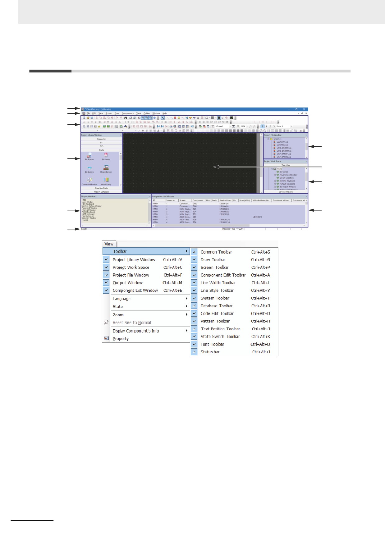
The displayed contents in the screen are shown as below when the NB-Designer is running.
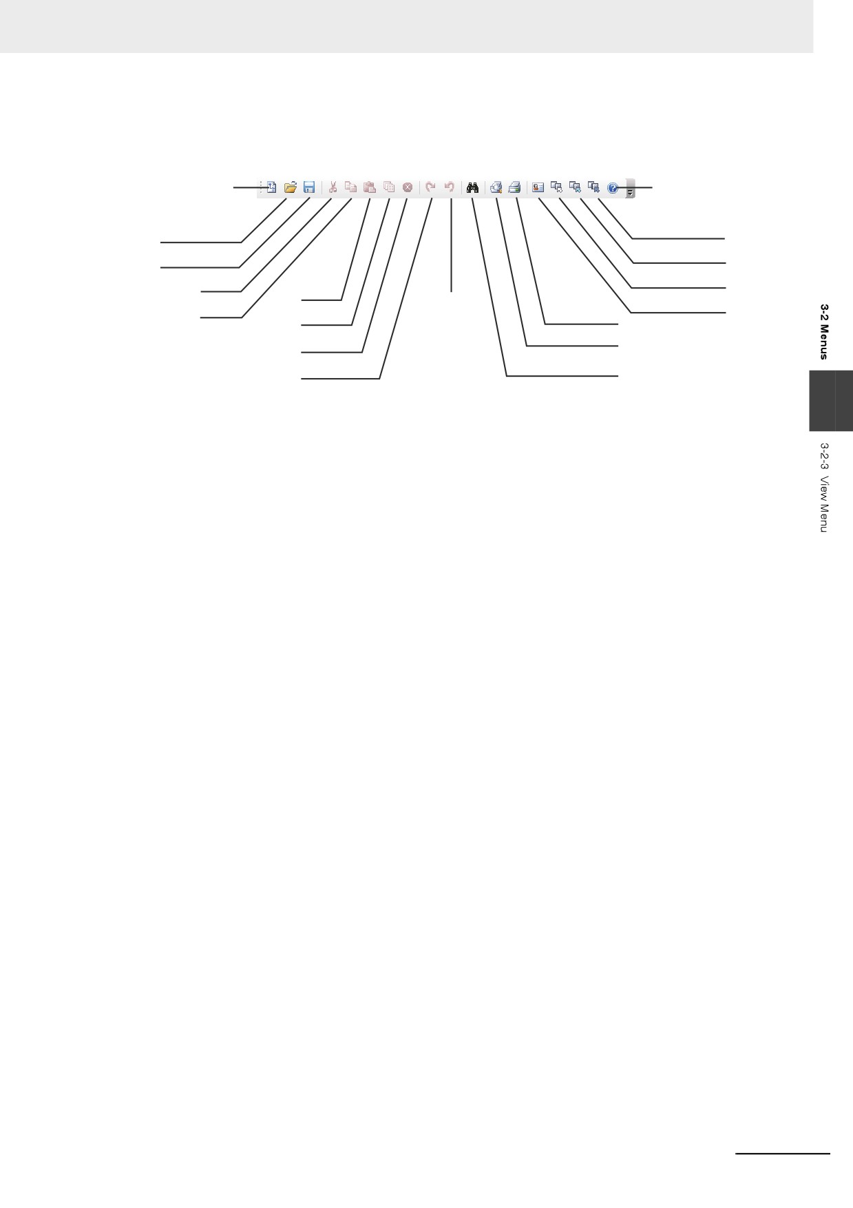
You can also right-click [View] - [Toolbar] or toolbar to see each toolbar shown as below.
Title
Menu
Toolbar
Project file
window
Project Library
window
Edit
window
Project Work
Space
Output
Component list
window
window
Status bar
z Title
Editing project file name and others are displayed.
z Menu
Selects the various kinds of command menus of NB-Designer. After these menus being selected,
the corresponding pull-down menu will pop up. Each pull-down menu corresponds to one command
operation.
3-4
3 Functions of NB-Designer
z
Toolbar
1
Common Toolbar
Includes some basic tools such as “New”, “Open”, “Cut” and “Copy” etc.
2
Draw Toolbar
Each image of figure drawing is displayed in icons. The available drawing tools include Line,
Rectangle, Ellipse, Sector, Polygon, Text etc.
3
Screen Toolbar
Performs Up/Down operation of the screen.
4
Component Edit Toolbar
Adjusts the position of the component (i.e. top-alignment, bottom-alignment, left-alignment,
3
right-alignment etc), the size, cascading, combination and flip methods.
5
Line Width Toolbar
Adjusts the width of the line in the figure.
6
Line Style Toolbar
Add or delete the arrow head, replace solid line with broken line in the figures.
7
System Toolbar
Performs the compilation, downloading and test of the project.
8
Database Toolbar
Includes text library, alarm information, Variable Table, PLC control and event information.
9
Code Edit Toolbar
The icon to edit macro is displayed.
10
Pattern Toolbar
Select the filling-style of screen background or the closed space such as rectangle, ellipse,
sector etc.
11
Label Component Edit Toolbar
Performs the alignments of the label such as label aligning to the left-border/right-border/top-
border or bottom-border of the component, label locating in the vertical center or horizontal
center of the component.
12
State Switch Toolbar
Simulates the switching of the various states of each component in the current screen and
languages.
13
Font Toolbar
Sets dot matrix/vector/graphics mode, font and font size of various kinds of texts displayed in
the screen.
3-5
3 Functions of NB-Designer
14 Status Bar Toolbar
Displays the information such as the current mouse position, the width/height of the destination
object and the editing state etc.
z
Project Library Window
6 columns in the Project Library Window are available.
Connector: Selects the communication cable type.
PT: Selects the PT type.
PLC: Selects the PLC type.
Parts: Selects various kinds of configuration parts.
Function Parts: Selects various kinds of multi-function parts.
Project Database: Selects some special functions.
z
Project Work Space
Project Work Space adopts tree view chart to show the relations of the PLC, PT, PT internal screens
and components in the whole project.
z
Project File Window
Project File Window adopts tree view to show the correlations between the PT and bitmap files
related to the project, and all the information of the files (such as the recipe files, macro files and
graphics library files etc) contained in the project.
z
Output Window
For details, refer to 3-3-4 Output Window (Page 3-45).
z
Component List Window
For details, refer to 3-3-1 Project Library Window (Page 3-35).
z
Configuration and Setup Window, Edit Window
Users setup configurations or create drawings in the window.
3-6
3 Functions of NB-Designer
3-2
Menus
There are various kinds of menus in NB-Designer. You can set the object, graphics, chart, macro, data
block etc, and create the screen data displayed on the NB Unit. The pull-down menu list and the
purposes of each item are as follows.
3-2-1
File Menu
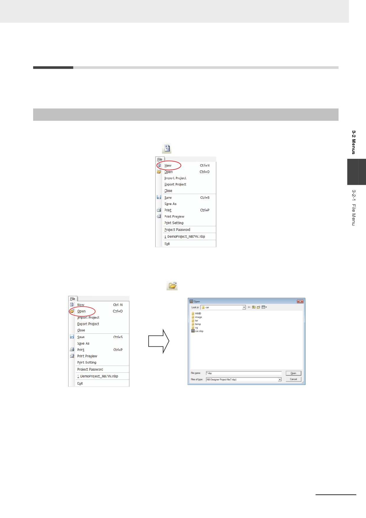
z New
Select [New] in the [File] menu or
icon to create a new project.
3
A new project is created when you press [OK] after inputting the project name.
z Open
Select [Open] in the [File] menu or
icon to open an existing project.
Select the project file to be opened, and press [Open] or double click this project file.
3-7
3 Functions of NB-Designer
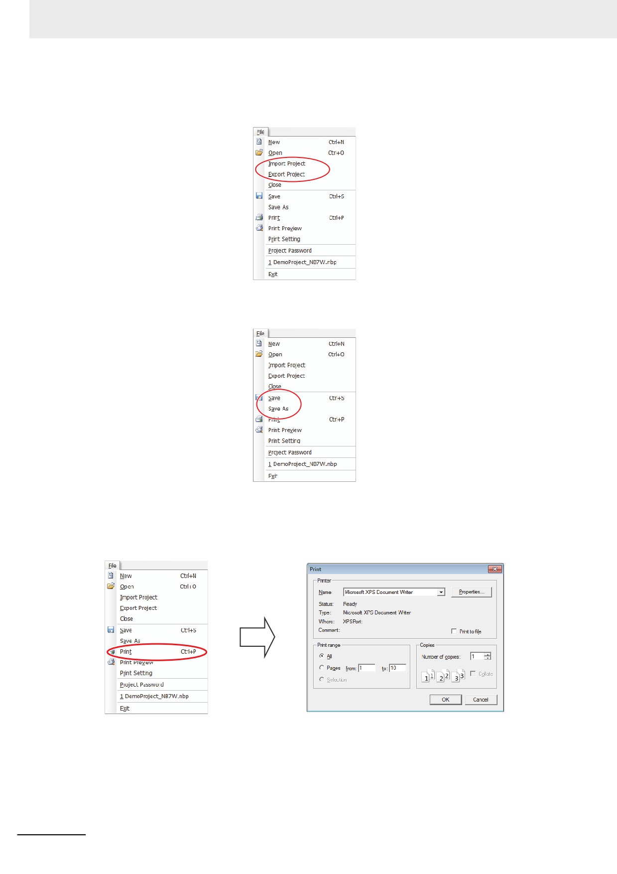
z Import Project/Export Project
Select [Export Project] in the [File] menu to save an opened project as a pkg file. Select [Import
Project] in the [File] menu to import an existing pkg file.
z Save
Select either of “Save” and “Save As”.
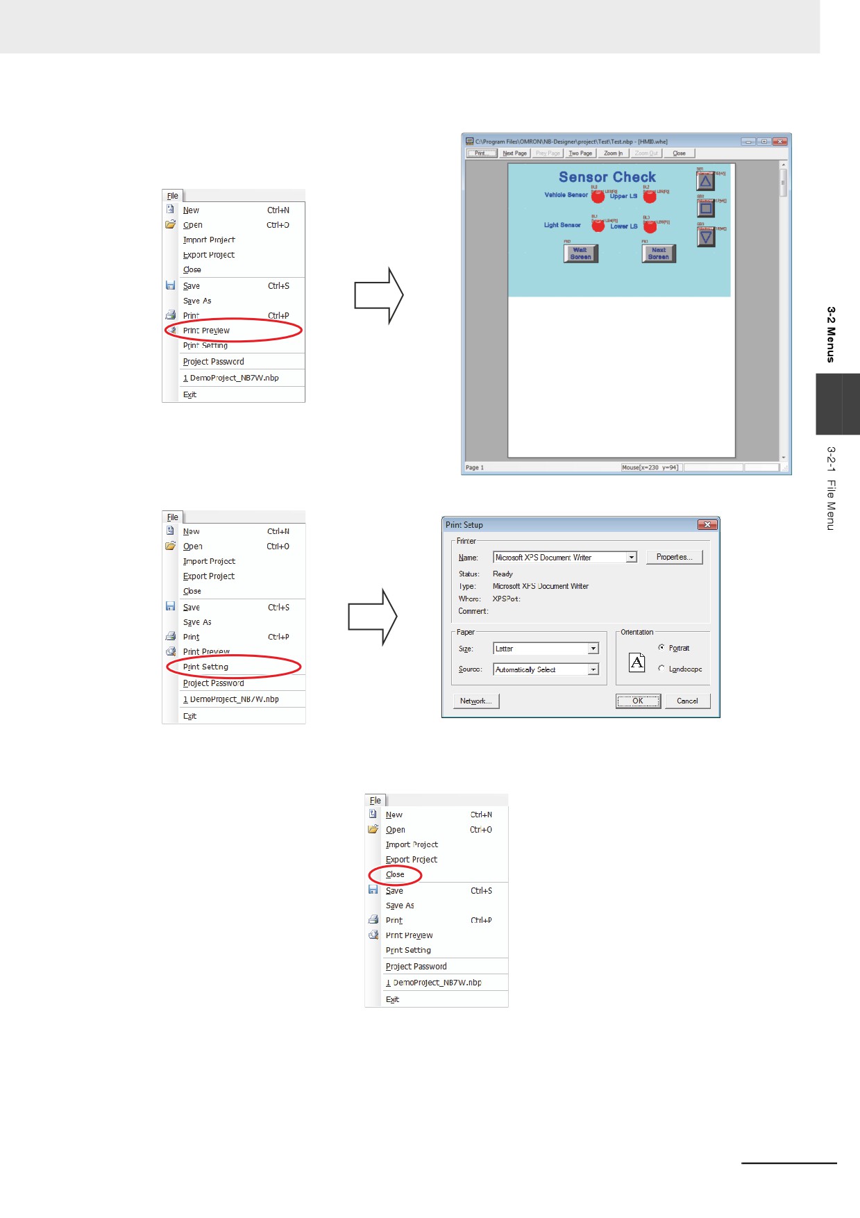
z Print
Select a project data and open a screen to enable this function. This functionality will allow the user
to print screen images.
Click [Print] to open print setup window.
3-8
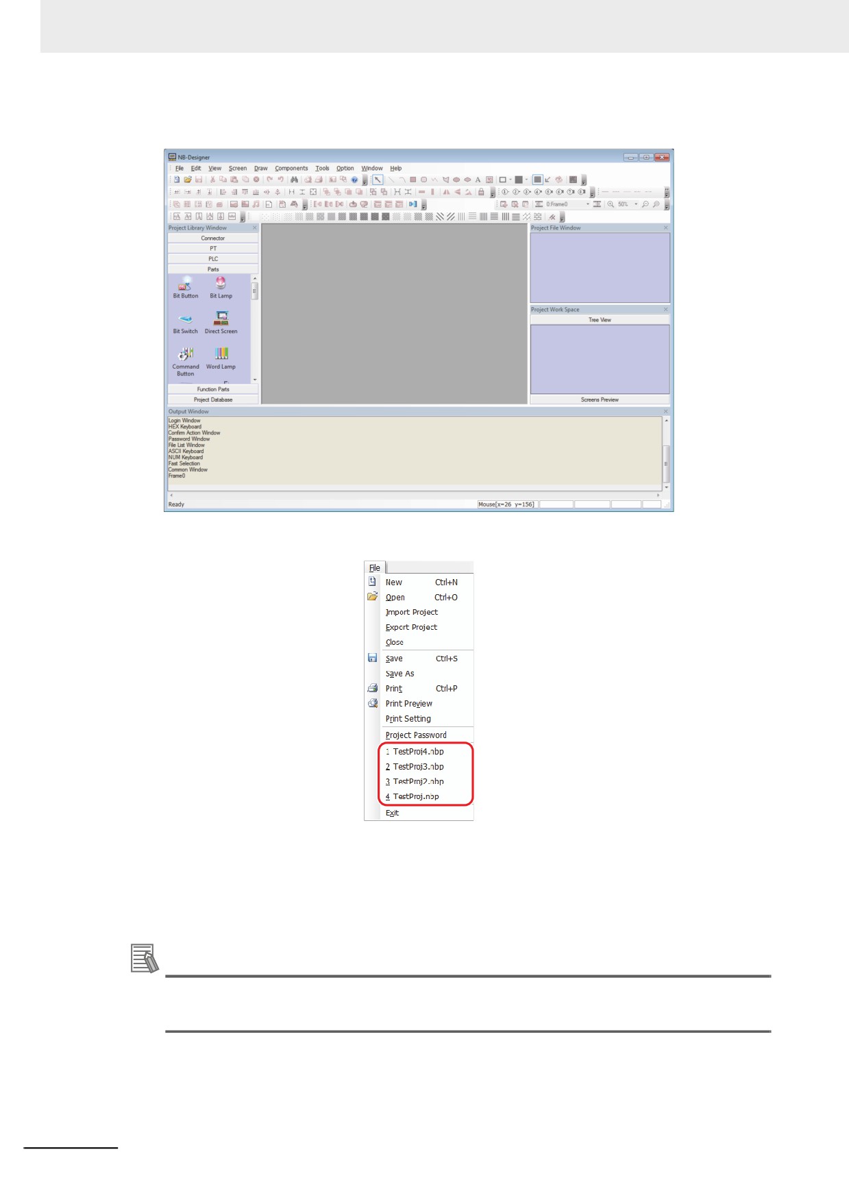
3 Functions of NB-Designer
Select [Print Preview] to display a preview window.
3
To display the Print Setup window, click [Print Setting].
z Close
Select [Close] in the [File] menu to close the current project.
3-9
3 Functions of NB-Designer
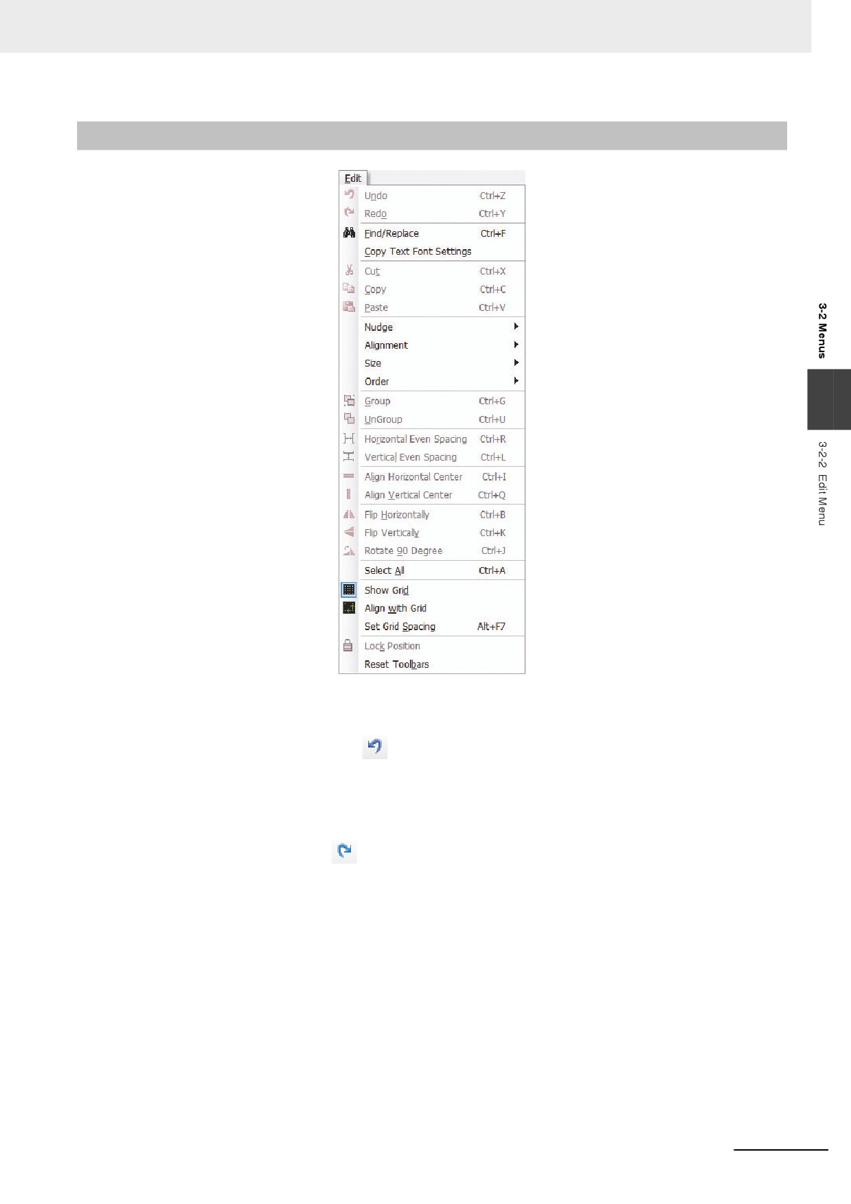
All the current windows will be closed after “Close” being pressed, and the display screen is shown
as below.
z List up the 4 projects opened recently
z Exit
Exit the NB-Designer software.
Note When Free-editing multiple project screens, adds the multiple-project-simultaneous-opening function,
thus making the copy of the component in the editing screens of two projects available.
Additional Information
Operations related to files cannot be executed via networks.
Do not use the system locale-dependent characters for the project file name and folder name.
3-10
3 Functions of NB-Designer
3-2-2
Edit Menu
3
z Undo
The latest operation can be cancelled by using this function, and the screen will return to the state
before this operation. Pressing
icon or selecting [Undo] in the [Edit] menu can cancel the
latest operation.
z Redo
Using this function after performing “Undo” operation can restore the “Undo” operation done just
now. It just needs to press
icon or select [Redo] in the [Edit] menu.
The operations supported by “Undo” and “Redo” are as follows.
(1) Dragging a part or a functional part from the Project Library Window
(2) Drawing a component
(3) Moving the object
(4) Adjusting the object size
(5) Performing all the operations with the Component Edit Toolbar
(6) Selecting the line width, line style or arrow
(7) Selecting the object filling style
(8) Selecting the object border color
(9) Selecting the object filled color
(10)Performing “Set Top Layer” and “Set Bottom Layer” operations
(11)Performing cut, copy, paste and deletion
3-11
3 Functions of NB-Designer
(12)Performing the Repeat operation
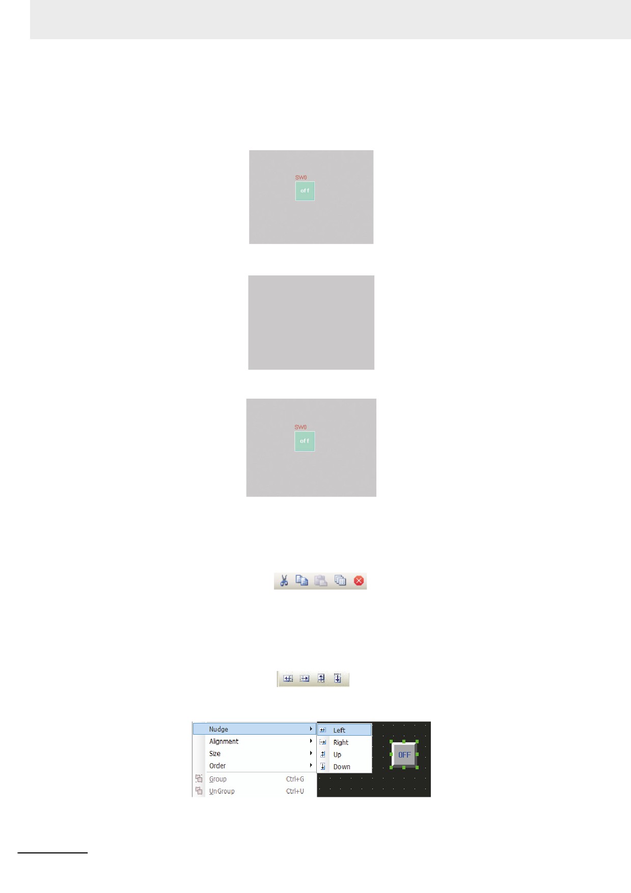
An example of operation in which a bit switch component is added to the PT screen and [Undo] or
[Redo] is performed to the addition is provided as below.
Press [Undo].
Then press [Redo].
Note The software only supports single-step “Undo/Redo” operation.
z Cut, Copy, Paste and Delete
After selecting one component or more, you can cut, copy, paste it or them etc, and the
corresponding icons are shown as
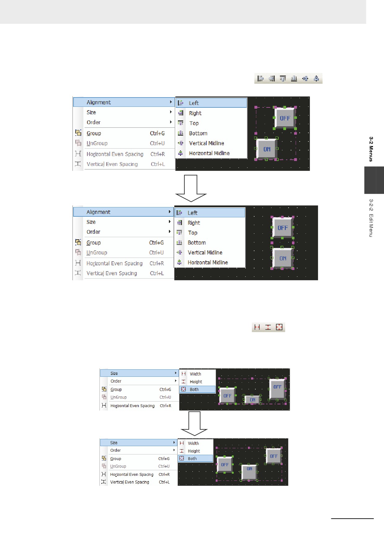
z Nudge
The component position can be adjusted by “Nudge” method after it is selected. The component
movement can be realized by using direction key or the corresponding [Nudge] icons. Each time the
“Nudge” button is pressed, the component will move a pixel distance accordingly. The
corresponding icons are shown as
and they are “Left”, “Right”, “Up”, “Down”
corresponding one-to-one with the contents of [Nudge] in the [Edit] menu. The simple nudge method
is to use the arrow keys on the keyboard, which realizes the easy component movement.
3-12
3 Functions of NB-Designer
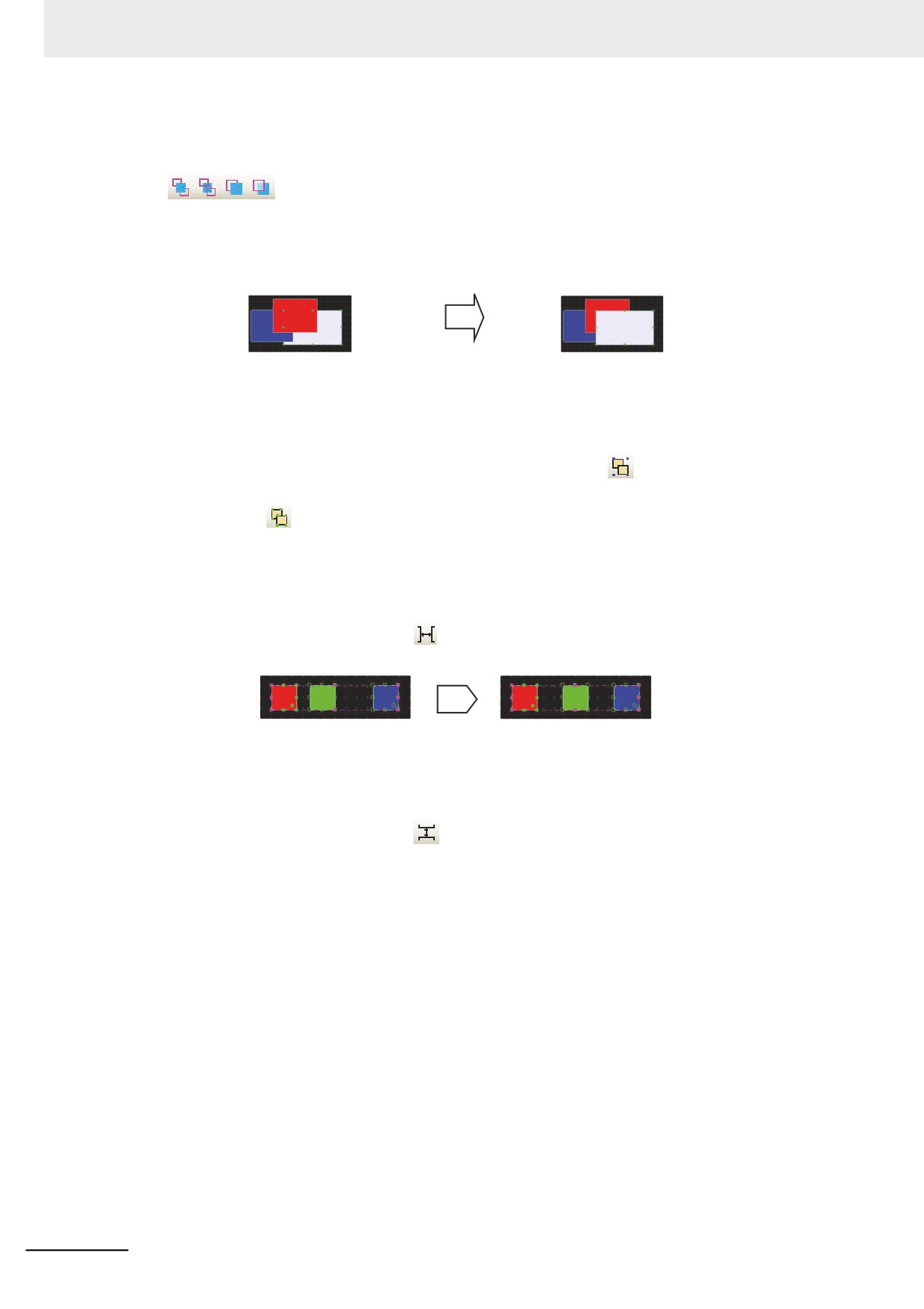
z Alignment
Makes the selected component realize the Left, Right, Top, Bottom, Vertical Midline or Horizontal
Midline alignment. The corresponding icons are shown as Here
only take
“Left” as an example with the effect shown as below.
3
z Size
To make the multiple components with the same width, height or size, you just need to press the
corresponding icons for adjusting the size of the component, or to select the options in the
corresponding menus. The corresponding icons are shown as
and they are “Width”,
“Height” and “Both” respectively. Unify the size for all components according to the size of the
component is located in the left end among all the components. If you want to specify a certain
component as the reference, select other components after pressing the [shift] key to select the
reference.
3-13
3 Functions of NB-Designer
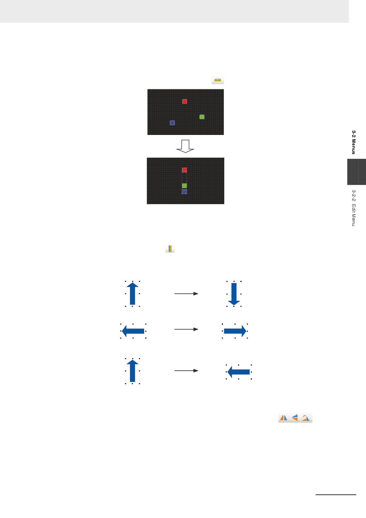
z Order
When the multiple components are overlapped together, you can use the icons shown as
(Bring to Front, Send to Back, Bring Forward, Send Backward) or select [Bring to
Front], [Send to Back], [Bring Forward], [Send Backward] in [Order] of the [Edit] menu to change the
display order of the components.
Firstly select the component and set the layer of the component by pressing the corresponding icon.
The component in the front layer is always displayed above that in the back layer.
Set Top Layer
z Group/UnGroup
This function is used to make the multiple selected components or graphics combined together as a
separate component. To make multiple components combined together, it just needs to select these
components, and then select [Group] in the [Edit] menu or press
icon. To cancel the
combination, it only needs to select this combined component, then select [UnGroup] in the [Edit]
menu or press
icon.
z Horizontal Even Spacing
This function is used to make the horizontal space between the multiple selected components or
graphics same. Select the graphics or components to be operated, and then select [Horizontal Even
Spacing] in the [Edit] menu or press
icon. Clicking the icon allows the components lined as
below.
z Vertical Even Spacing
This function is used to make the vertical space between the multiple selected components or
graphics same. Select the graphics or components to be operated, and then select [Vertical Even
Spacing] in the [Edit] menu or press
icon.
3-14
3 Functions of NB-Designer
z Align Horizontal Center
This function is used to make the multiple selected components or graphics located in the horizontal
center of the Edit Window. Firstly select the components or graphics to be operated, and then select
[Align Horizontal Center] in the [Edit] menu or press
icon, as shown below.
3
z Align Vertical Center
This function is used to make the multiple selected components or graphics located in the vertical
center of the Edit Window. Firstly select the graphics to be operated, and then select [Align Vertical
Center] in the [Edit] menu or press
icon.
z Flip
Only shapes (such as line, circle, polygon etc) drawn by drawing tools rather than other components
can be flipped. Firstly select the graphics to be operated, and then select [Flip Horizontally], [Flip
Vertically, [Rotate 90 Degree] in the [Edit] menu or select the corresponding
icons to
flip the components.
3-15
3 Functions of NB-Designer
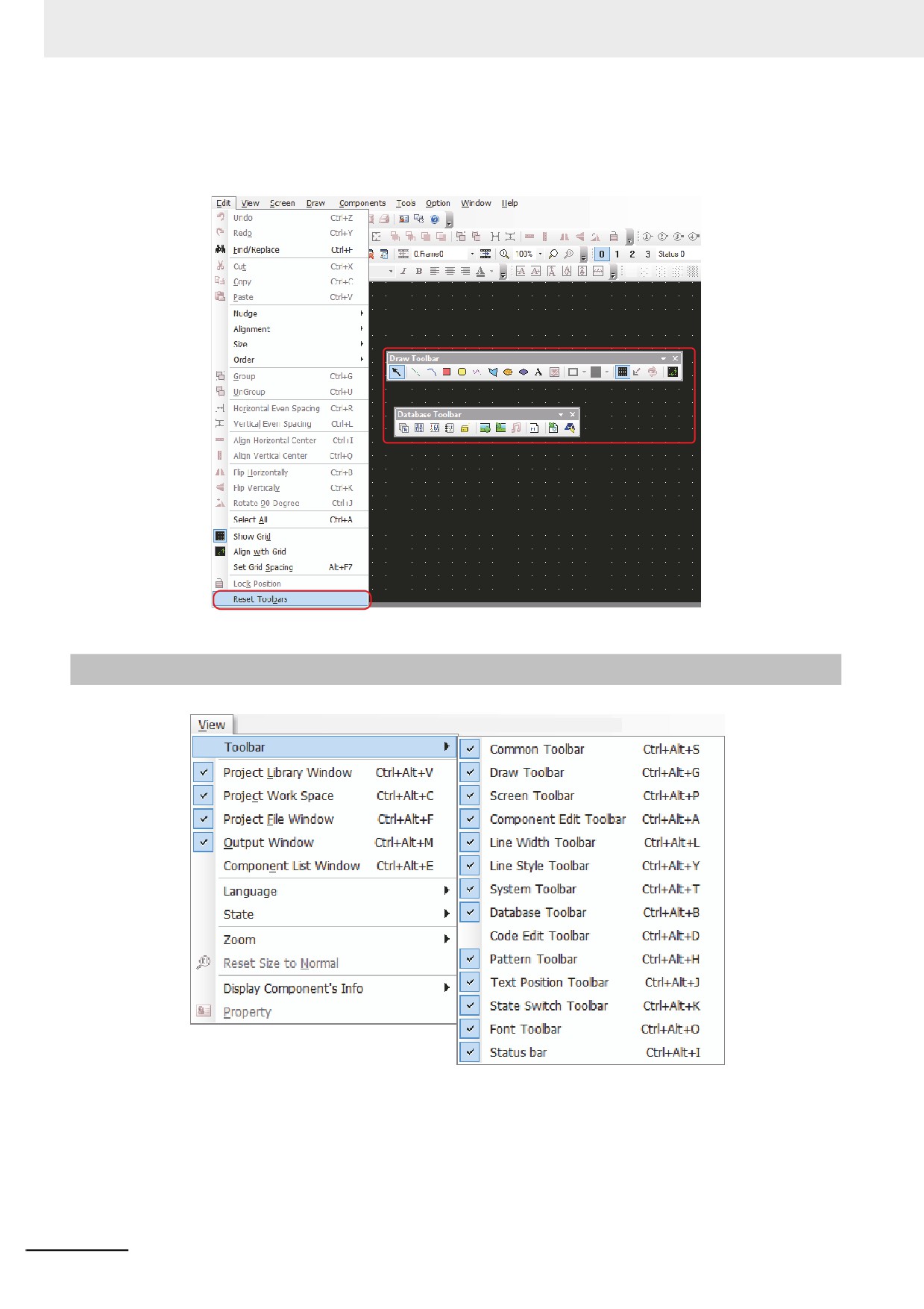
z Reset Toolbars
When the toolbar is moved to the other position, it can be restored to the default position by clicking
this option, as shown below.
3-2-3
View Menu
The options in the [View] menu are used to control the various kinds of toolbars to be displayed or not.
3-16
3 Functions of NB-Designer
z
Common Toolbar
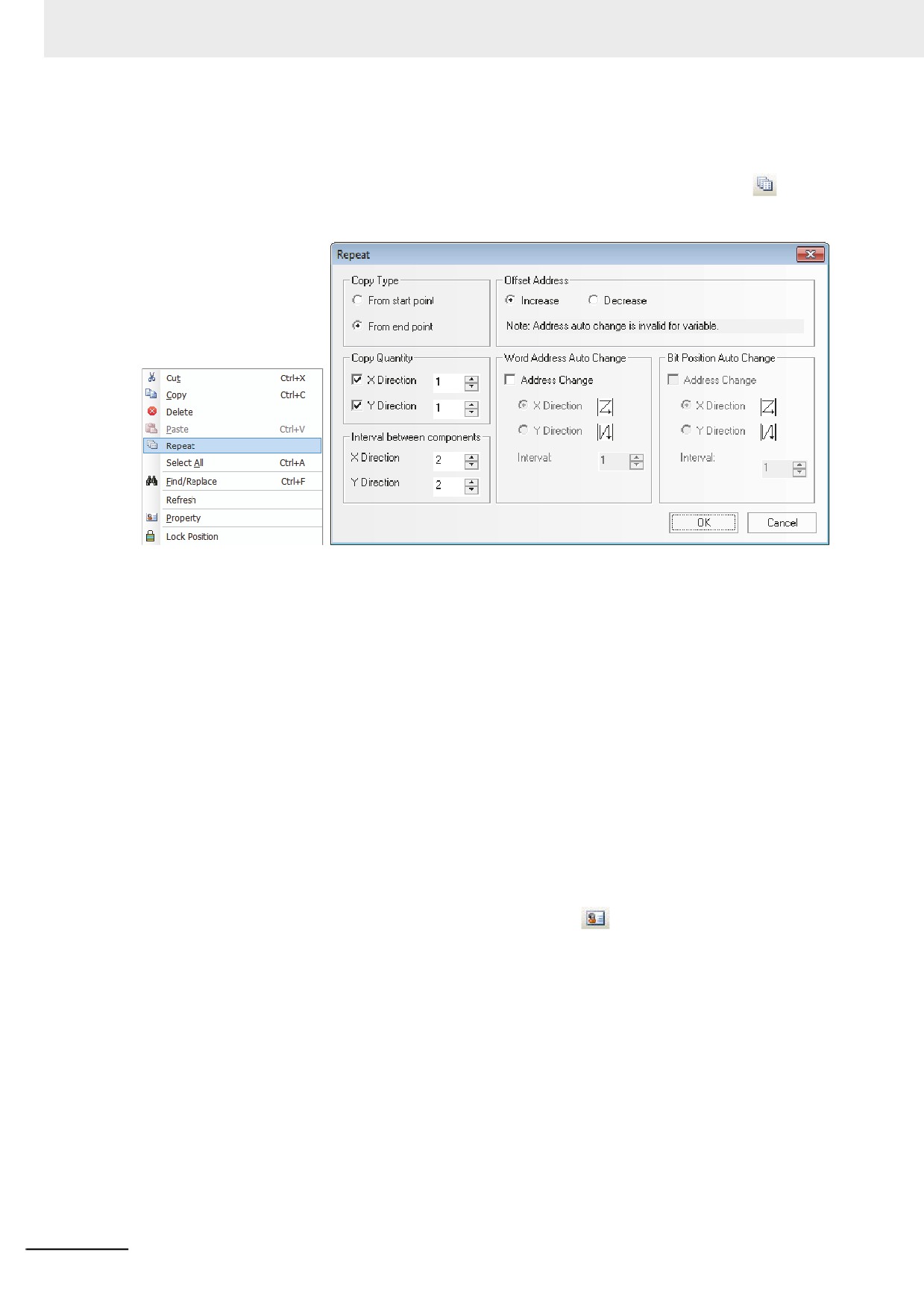
The correspondences of all the items (i.e. the icons here) in the standard toolbar to the options in
the menus are shown as below.
New Project
About
Display Address
Open Project
Display PLC
Save Project
Display Name
Cut
Paste
UnDo
Property
Copy
Repeat
Print
Print Preview
Delete
ReDo
Find/Replace
[New Project]: To create a new project
3
[Open Project]: To open an existing project
[Save Project]: To save the current project
[Cut]: To perform cutting operation
[Copy]: To perform copy operation
[Paste]: To perform paste operation
[Repeat]: To perform Repeat operation
[Delete]: To delete the component
[Redo]: To restore the latest cancelled operation
[Undo]: To cancel the latest operation procedure
[Find/Replace]: To search the memory addresses used in the current project, screen or macro and
perform the replacement
[Print Preview]: To preview the print effect
[Print]: To print
[Property]: To show the object Properties
[Display Name]: To display/hide the component’s name
[Display PLC]: To display/ hide the component's PLC name
[Display Address]: To display/hide the component's address
[About]: To describe the version information of NB-Designer
3-17
3 Functions of NB-Designer
z Repeat
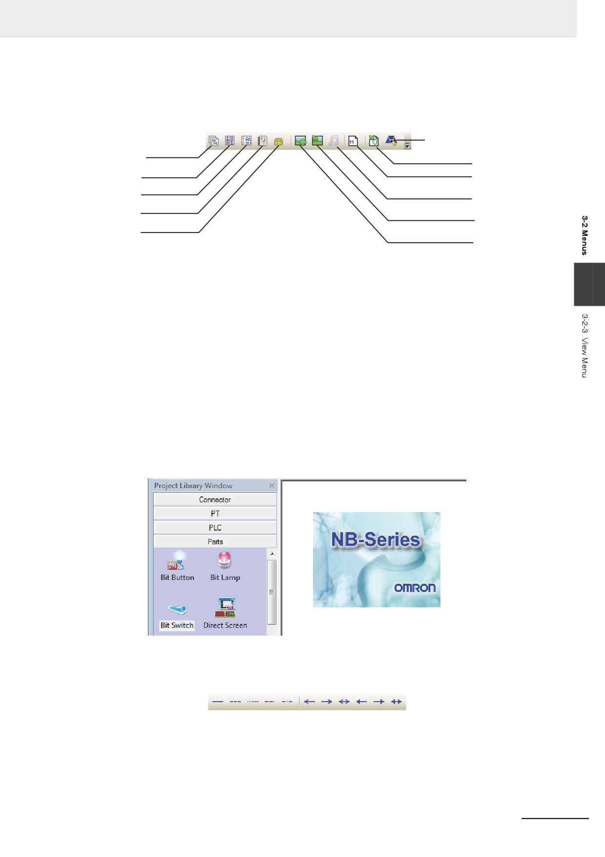
With this function, one component can become multiple components through the copy operation,
thus saving a lot of time. You can make the multiple components available by clicking
icon or
right-clicking [Repeat] in the corresponding menu after the component being selected, as shown
below.
Copy Type: Selecting [From start point], the copied component to be arranged according to the
upper left top of the component as the reference point.
Selecting [From end point], the copied component to be arranged according to the lower right top of
the component as the reference point.
Copy Quantity: The number of the copied component in each line and each column.
Interval between components: Specifying the horizontal interval and vertical interval between the
two of the copied components.
Offset Address: The address of the copied component increases/decreases in X, Y directions.
Word Address Auto Change: The word address of the copied component increases/decreases in X,
Y directions.
Bit Position Auto Change: The bit address of the copied component increases/decreases in X, Y
directions.
Interval: To select the address increment among the copied components.
[Property]: When changing the property of the components, select and double-click the component
which is necessary to change the property. Also clicking the
icon and displaying [Property]
dialog box allow the property of the component edited.
3-18
3 Functions of NB-Designer
z
Database Toolbar
The correspondences of all the items (i.e. the icons here) in the toolbar to the options in the menus
are shown as below.
Edit Logo Screen
Text library
Import Recipe Data File
Variable Table
Add Macro
Alarm Setting
Sound library
Event Setting
Import Graphics
PLC Control
Add Graphics
[Text Library]: To register the text string for the labels.
[Variable Table]: To register the variable information
3
[Alarm Setting]: To memory the alarm information
[Event Setting]: To memory the event information
[PLC Control]: To register the PLC control configurations
[Add Graphics]: To create the new bitmap or Vector Graphics
[Import Graphics]: To import the bitmap or Vector Graphics
[Sound Library]: To add the audio file (The NB Series does not support the function.)
[Add Macro]: To add the Macro
[Import Recipe Data File]: To import the recipe file
[Edit Logo Screen]: Click this button to make the screen switch to the logo edit screen. therefore you
can make modification or editing the logo screen displayed when the PT is powered on, as shown
below.
z Line Style Toolbar
Adding or deleting the arrow head or replacing solid line with broken line.
3-19
3 Functions of NB-Designer
z Component Edit Toolbar
[Nudge Left]: To make the component move left by 1 grid
[Nudge Right]: To make the component move right by 1 grid
[Nudge Up]: To make the component move up by 1 grid
[Nudge Down]: To make the component move down by 1 grid
[Align Left]: To make the multiple components left-aligned
[Align Right]: To make the multiple components right-aligned
[Align Top]: To make the multiple components top-aligned
[Align Bottom]: To make the multiple components bottom-aligned
[Align Horizontal Midline]: To make the multiple components horizontal-midline-aligned
[Align Vertical Midline]: To make the multiple components vertical-midline-aligned
[Equal Width]: To make the multiple components with the same width
[Equal Height]: To make the multiple components with the same height
[Equal Size]: To make the multiple components with the same size
[Bring to Front]: To bring the component to top layer
[Send to Back]: To send the component to bottom layer
[Bring Forward]: To bring the selected component to previous layer
[Send Backward]: To send the selected component to next layer
[Group]: To make the multiple components combined together
[UnGroup]: To cancel the combination of the multiple components
[Horizontal Even Spacing]: Arranging the multiple components in a horizontal row with equal interval
each by the middle point as reference point.
[Vertical Even Spacing]: Arranging the multiple components in a vertical row with equal interval each
by the middle point as reference point.
[Align Horizontal Center]: To make the center(s) of one component or multiple components located
in the horizontal center of the PT Edit area
[Align Vertical Center]: To make the center(s) of one component or multiple components located in
the vertical center of the PT Edit area
[Flip Horizontally]: To perform horizontal flip
[Flip Vertically]: To perform vertical flip
[Rotate 90 Degree]: To rotate the component 90 degree clockwise
[Lock Position]: To lock the position of the component
z
Label Component Edit Toolbar
Click the component, and then click the label displayed later to select it. Later when you see the
label is not gray any more, you can set the position of the label as required (e.g. Left Label, Right
Label, Top Label, Bottom Label, Vertical Middle Label and Horizontal Middle Label).
3-20
3 Functions of NB-Designer
z Draw Toolbar
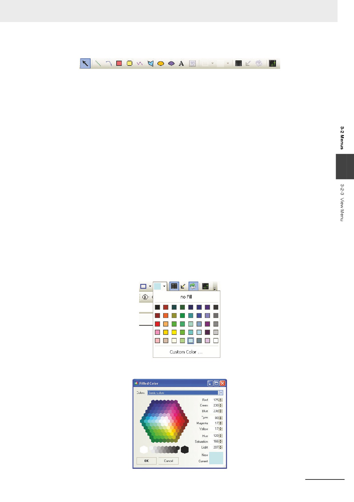
The contents of the items in the Draw Toolbar are shown as below.
[Select]: To select one component or multiple components
[Line]: To draw a line
[Arc]: To draw an arc
[Rect]: To draw a rectangle
[Round Rect]: To draw a rounded rectangle
[Polyline]: To draw a consecutive line
[Polygon]: To draw a polygon
[Ellipse]: To draw a circle or ellipse
3
[Sector]: To draw a sector
[Text]: To add the text
[Load Graphic]: To add the bitmap in the editing window
[Frame Color]: To set the frame color for the shapes
[Background Color]: To set the background color for the shapes
[Show Grid]: To make the grid displayed in the screen
[Transparent Color]: To add transparency to the added bitmap
[Multicolor-Grayscale Switch]: To make the transformation between the color and black/white
[Align with Grid]: After the component being selected, click this button once to make the grid point as
the moving unit, and click it twice to restore the default pixel point as the moving unit of the
component.
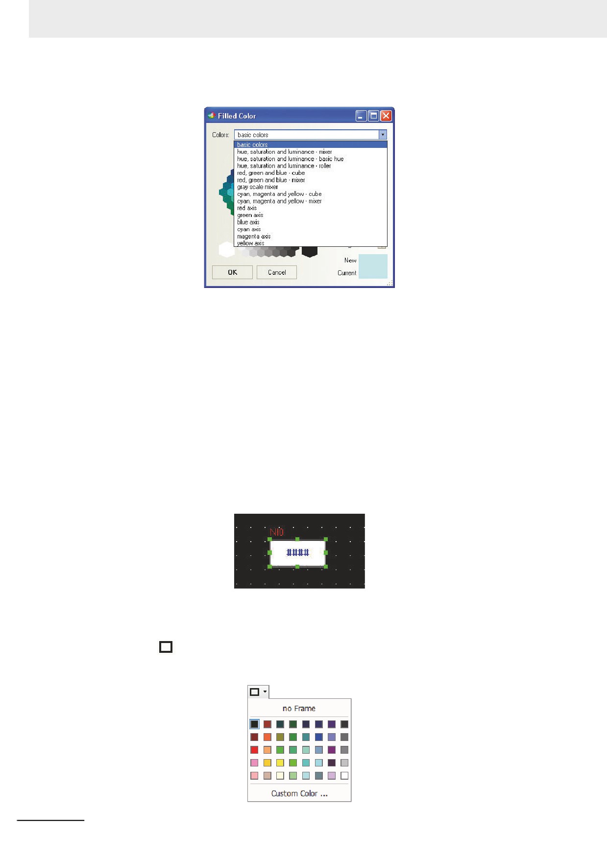
For the color setup, there are 40 kinds of colors available, as shown below.
Besides the 40 kinds of colors shown above, the custom colors are also available. The following
dialog box will be displayed after clicking “Custom Color…” at the bottom.
3-21
3 Functions of NB-Designer
Here you can select any color you want to have. In addition, there are also several color Properties,
as shown below, available to you.
z Select Component
The selection methods of the components are as follows.
(1) Direct selection: The component can be selected by using the mouse directly to click it.
(2) Selecting all the components: All the components in the current screen can be selected by
using [Select All] in the [Edit] menu.
(3) The multiple components can be selected by clicking them consecutively while pressing the
[Shift] key.
Note The copy operation can be performed by clicking the component to be copied while pressing the [Ctrl] key.
z Modify Component Size
The modification of the component size can be made by clicking the component. The specific
method is as follows: select any one of the eight green points on the component, as shown below,
after the component being selected, and then drag it by using the mouse.
Note The white dots displayed on the component mean that the text is selected. If you should change the size of
component, click the area without a text to select whole the component.
z Fill Component and Frame
To change the frame or the background color of the shapes, it just needs to click the small arrow
behind the
“Frame Color” icon after the component being selected to change the frame color,
and to click the small arrow displayed in the right to the [Background Color] icon change the
background color of the shapes, as shown below.
3-22