OMRON NB-Designer OPERATION MANUAL (NB-series, 2020) - page 9
3 Functions of NB-Designer
Descriptions of Switch Screen
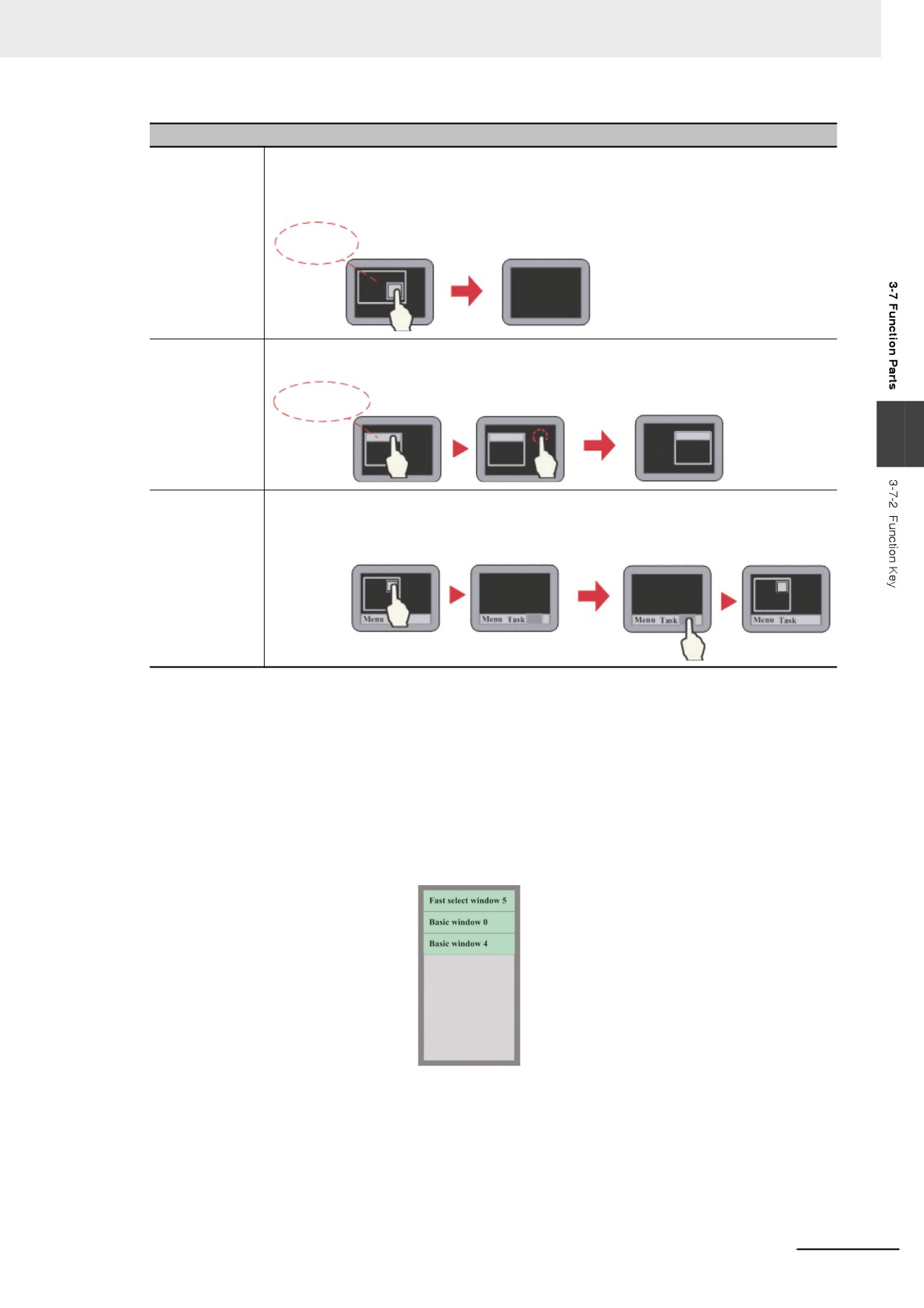
Close Screen
Closing the Pop-up Screen which is displayed in the screen placed with a function key. The
screen operations with the function do not perform write of the data for the address of
control which is set by the Direct Screen or Indirect Screen. Therefore, make sure that point
when the Direct Screen or Indirect Screen is used.
Pop-up
Screen
Frame 0
Frame 0
Title bar on
Pressing the Function Key can move the Pop-up Screen to the specified position in the
Pop-up Screen
screen, which is effective for Pop-up Screen, Indirect Screen and Direct Screen.
Title Bar
Frame 0
Frame 0
Frame 0
3
Minimize
After the Function Key is pressed, the Pop-up Screen will minimize to the Taskbar.
Pressing this icon will make the screen return to its original position. This function is
effective for Pop-up Screen, Indirect Screen and Direct Screen.
Frame 0
Frame 0
Frame 0
Frame 0
Example: Screen switching function
(1) Create a new project and save it.
(2) Create each of Fast select window 2, Common window 1, Basic window 4, Fast select
window 5, Common window 6, Pop-up window 7. The Fast select window 2 and the Fast
select window 5 are the same size ((100, 220) in this case) and the Pop-up window 7 is the
smaller that other screens (it is ((200,150) in this case).
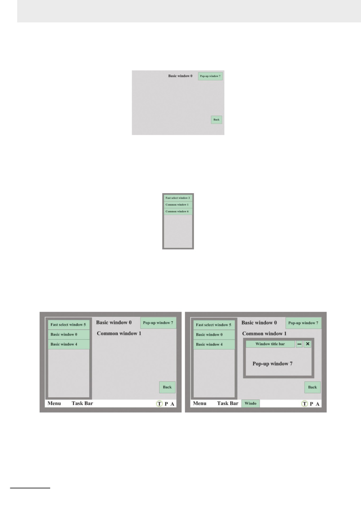
(3) Create three function keys in the Fast select window 2.
Three function keys such as [Change Screen] function key ti switch to Basic window 0,
[Change Screen] function key to switch Basic window 4, and [Change Menu Screen]
function key to switch to Fast select window 5 to switch the Base Screen shown as below.
(4) Place one text component displaying “Common window 1” displayed in Common window 1.
3-203
3 Functions of NB-Designer
(5) Place one text display component to display “Basic window 0” in the Basic window 0 as
below. Also place [Pop-up Screen] function key to display “Pop-up window 7” and
[Backward] function key in the Basic window 0.
(6) Place one Text Display component to display “Basic window 4” and [Backward] function
key in the Basic window 4.
(7) Create three Function Keys in the [Fast select window 5].
Three Function keys such as a [Change Common Sheet] Function Key to switch Common
Sheet into Common window 1, a [Change Common Sheet] Function Key to switch
Common Sheet into Common window 6, and [Change Menu Screen] Function Key to
switch Menu Screen into Fast select window 2 as follows.
(8) Place one Text Display component to display “Common window 6” in the Common window
6.
(9) Place three Function Keys in “Pop-up Screen” in Pop-up window 7. Three Function Keys
such as one [Title bar on Pop-up Screen] Function Key to display “Pop-up window 7”, a
[Minimize] Function Key, and one [Close Screen] Function Key.
(10)After the completion of setup, saving the project file and executing the off-line test after the
compilation, the project is displayed as below.
(11)When switching the “Basic window 0” into “Basic window 4” by the button in Menu Screen,
pressing “Back” button allows the screen returned to “Basic window 0” and then pressing
“Back” button in the Basic window 0 allows the screen returned to “Basic window 4”.
(12)When [Pop-up Screen] is pressed in “Basic window 0”, “Pop-up window 7” will pop up, as
the upper right graphics shown.
3-204
3 Functions of NB-Designer
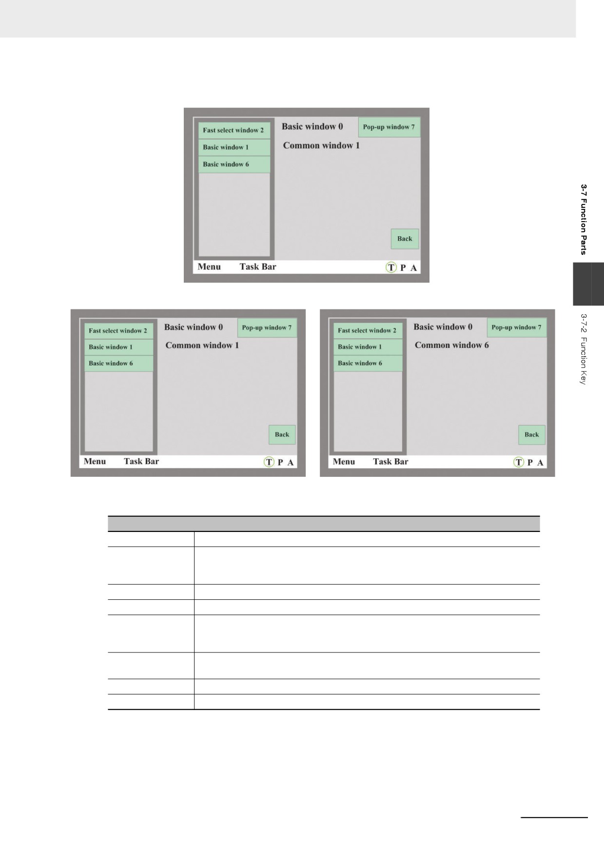
(13)Pressing [Fast selection window 5] in Menu Screen will make the screen switch to Fast
selection window 5, as shown below.
3
(14)Pressing [Common Sheet 1/6] can realized the switching among the Common Sheet.
2
Keyboard Function
Descriptions of keyboard function
Enter
Equivalent to the function of Enter key in the keyboard.
Back Space
When entering numbers or Text strings in the component [Number Input] or the
component [Text Input] by Function Keys, remove one character which is placed
immediately before the input cursor.
Clear
Clears the contents input to “Number Input” and “Text Input” components.
Escape
Cancels the input operation, equivalent to the function of Esc key in the keyboard.
Unicode
Sets the input characters including “0, 1, 2, …” on the number keys, ASCII codes
like a, b, c etc or Unicode characters for “Number Input” and “Text Input”
components.
Cursor
Includes “Up”, “Down”, “Left”, “Right”, “Line head”, “Line tail”, “First position” and
“Last position”.
Select text
Includes “Start selecting” and “Finish selecting”.
Text operation
Includes “Copy”, “Cut” and “Paste”.
3-205
3 Functions of NB-Designer
Example: Making NUM Keyboard
Number (0 to 9) keys, Float, Minus sign, Enter, CLR and Backspace keys are required in the
keyboard.
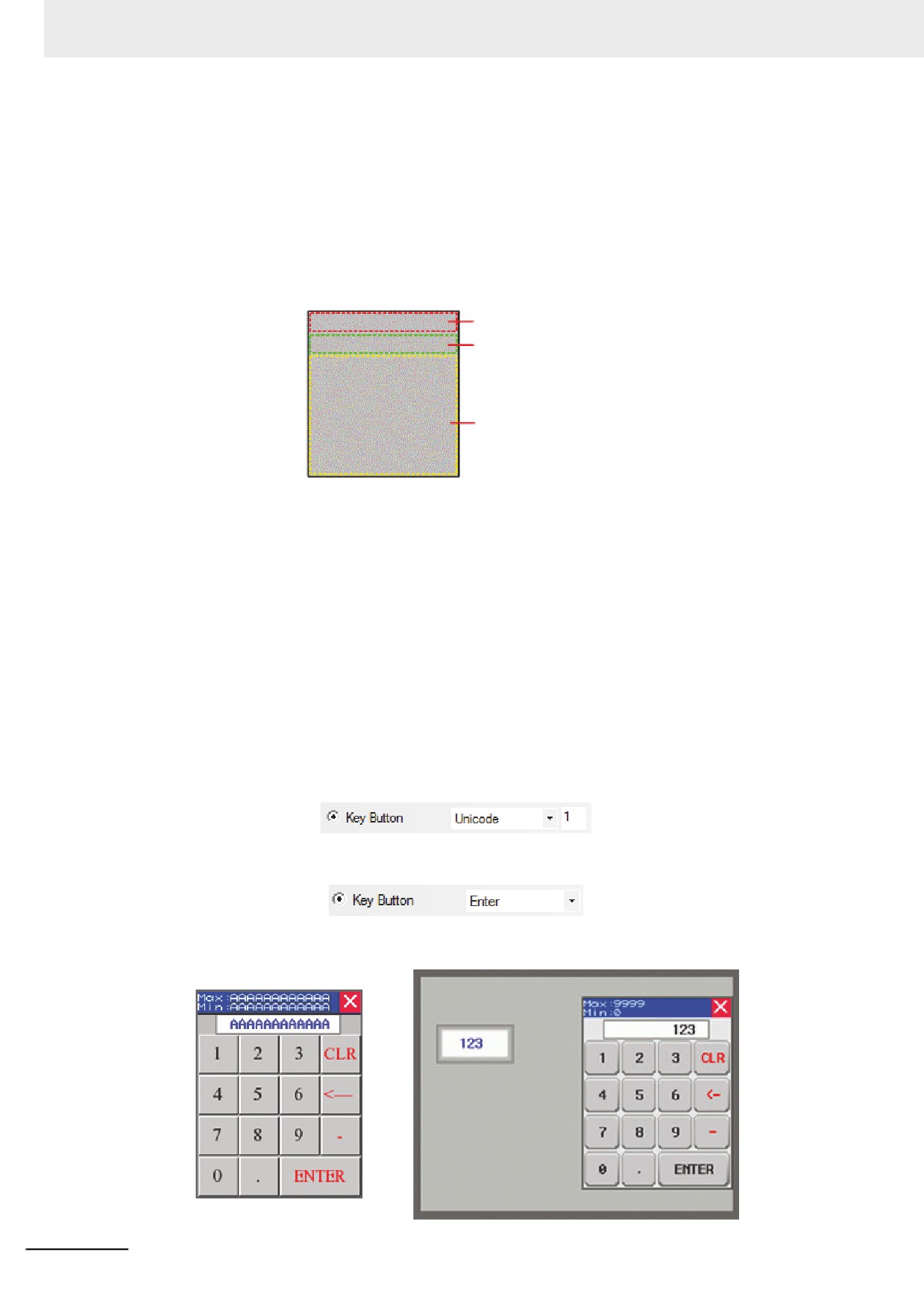
Step 1: Create a new project and make the layout of the NUM keyboard.
Firstly add the new screen “Frame 10” and open [Screen Property], then perform the screen
operations such as setting the Width, Height and the border width to be 160, 200 and 2
respectively, setting the Frame Color, checking [Screen Attribute] and setting it to be
“Keyboard page”. Finally divide Frame10 into three areas, i.e. Screen control area, Input
Display area and Keyboard area, as shown below.
Screen control area
Display area
Keyboard area
Step 2: Add the required components for the keyboard.
(1) Firstly, add one Function Key as screen title bar into the Screen control area, in this case,
select “Title bar on Pop-up Screen”.
(2) Add two Text Display components for displaying the ranges of the maximum and the
minimum for the Number Input, where the [Read Address] are LW9180 (LW9180 ~
LW9187 is the system special memory for displaying the maximum of Number Input) and
LW9190 (LW9190 ~ LW9197 is the system special memory for displaying the minimum of
Number Input) respectively and [Word Length] are both 6.
(3) Add one Function Key to close keyboard screen, i.e. to check [Key Button] and select
“Escape”.
(4) Add one Text Display component to input display box in the Display area with [Read
Address] set to LW9070 (LW9060 ~ LW9075 is the special memory which works as the
buffer of Number Input or Text Display Input.) and [Word Length] set to 6.
(5) Add twelve Function Keys as Character Input Keys in the Keyboard area. Take an example
to input [1]: Select “Unicode” after selecting [Keyboard Function], then input “1” in Input
area. And the operation for the other characters is similar to this operation.
Add three Function Keys as the special keys, i.e. select “Clear”, “Backspace” and “Enter”
respectively after selecting [Key Button] for the three Function Keys.
The final effects of the editing screen and the test are shown as the lower left and lower right
graphics respectively.
3-206
3 Functions of NB-Designer
Example: Create Unicode keyboard by the combination of Text Input and Function Key.
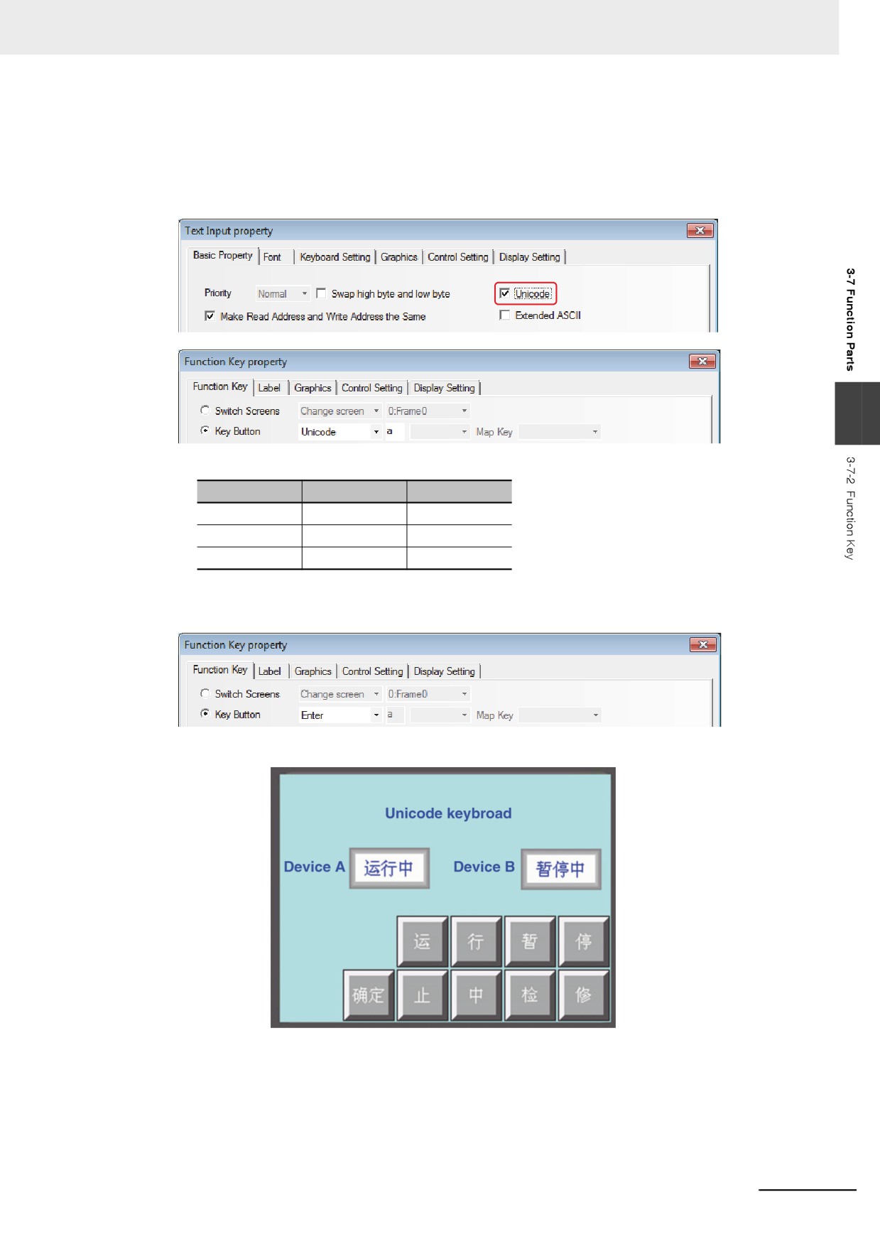
The Unicode keyboard can be created by using [Unicode] option, which is available in the
related Property screen of Text Display component, Text Input component and Note Book
component, in combination with the [Key Button] - [Unicode] option in the Function Key
Property.
3
(1) Make the following settings after adding two Text Input components.
Properties
Text Input A
Text Input B
Unicode
Unicode
Unicode
Address
LW0
LW3
Word Length
3
3
(2) Add the Function Key and set the character to be input.
(3) Add one [Enter] key, i.e. select “[Key Button] - [Enter]” in the “Key Button” tab.
(4) The final effect is as shown below.
Unicode function currently only supports Chinese, English, Japanese and the common
symbols.
3-207
3 Functions of NB-Designer
3
Execute Macro
After this function is selected, pressing the Function Key can execute the specified existing
Macro code. (Refer to 3-9-3 Macro Triggering (Page 3-273))
4
Touch Calibration
After this function is selected, pressing the Function Key can make the system go to PT Touch
Calibration Screen, thus allowing the users to perform touch calibrations to the PT.
5
Clear Event
After this function is selected, pressing the Function Key can clear the event information stored
in the recipe memory.
6
Notepad
Functions of Message Board
Function
Pen
Pressing the Function Key means the current function is the pen in
the Notepad.
Eraser
Pressing the Function Key means the current function is the eraser in
the Notepad.
Clear
Pressing the Function Key can clear the contents in the area selected
Block
by the mouse of the Notepad.
Pen Color
For setting the pen color.
Pen Size
For setting the pen size from the eight size available.
Clear
Removing all the contents in the Notepad.
For the procedures of operation method about the Notepad, refer to 3-7-7 Notepad (Page 3-
220).
z
There are four methods to clear the event information:
(a) By clicking the [Function Key] component to clear the event information after the [Clear Event]
option in [Function Key] tab in Function Key Property dialog box being checked. The event
information data stored in the recipe memory can be cleared by this method.
(b) By restarting the PT to clear the event information after the value of special system memory
LW10015 being set to 0. The event information data stored in the recipe memory can be cleared by
this method.
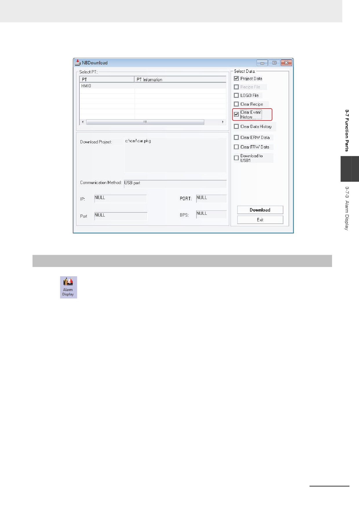
(c) Check in the [Clear Event History] option in [NBManager] dialog box and execute the download,
the event information will be cleared. The event information data stored in the recipe memory and
the event information files stored in the external memory can be cleared simultaneously by this
method.
(d) Check in the [Clear Event History] option in the NBDownload dialog box and execute the download
again. The event information data stored in the recipe memory and the event information files
stored in the external memory can be cleared simultaneously by this method, as shown below:
3-208
3 Functions of NB-Designer
3
3-7-3
Alarm Display
Alarm Display icon can be used to display the triggered preset alarm information by using the
Neon Lamp in the area where the Alarm Display locates. The alarm information must be related to node
address of a certain bit, and it will scroll from the right to the left when the bit address is triggered to the
alarm state. The alarm information will continue to scroll until this bit address is switched to the non-
alarm state. The alarm information must be logged in the [Alarm Setting] database in advance. (This
component only displays the alarm information, and the component to be displayed must be logged in
the [Alarm Setting] database).
3-209
3 Functions of NB-Designer
z Process of adding one Alarm Display
1
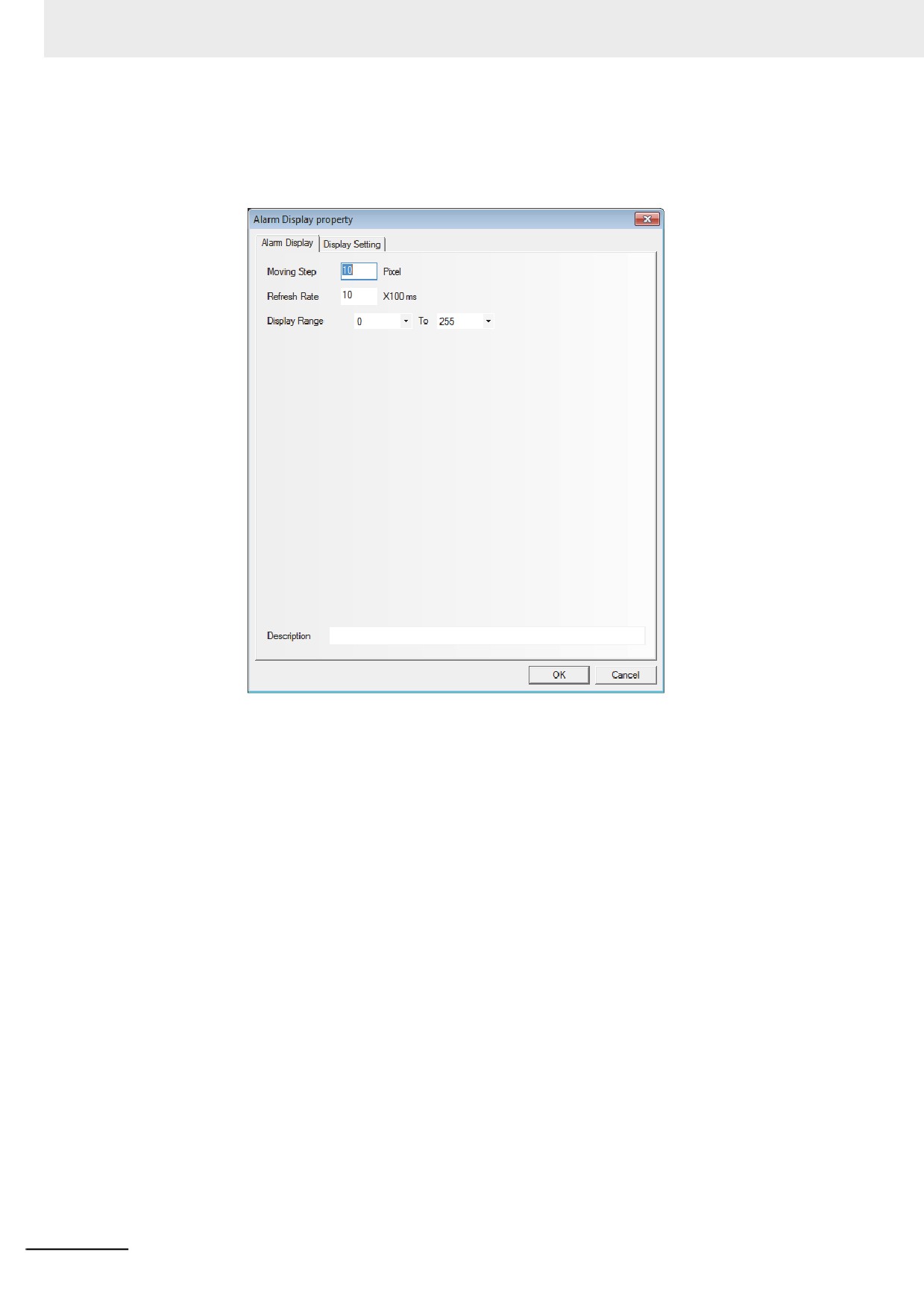
Press the Alarm Display icon, drag it to the screen, then the [Alarm Display Property] dialog
box will pop up.
Moving Step: Set the Moving Step in the unit of pixel. The larger the number of moving step,
the faster the speed of scroll display. The value is between 1 and 255.
Refresh Rate: Refers to the interval of each movement with the unit of 100 ms. The larger the
value of moving speed, the slower the speed of scroll display. The value is
between 1 and 10000 (i.e. 0.1 s to 1000 s).
Display Range: Set the range of alarm types to be displayed between 0 to 255. Restricting the
alarm types at this moment allows the display only optional alarm information.
Description: The descriptions can be entered to explain the Alarm Display components (the
descriptions will not be displayed in PT screen.).
2
Press the [OK] button to complete the setup.
3-210
3 Functions of NB-Designer
z Example of creating one Alarm Display component
1
Create a new project firstly.
2
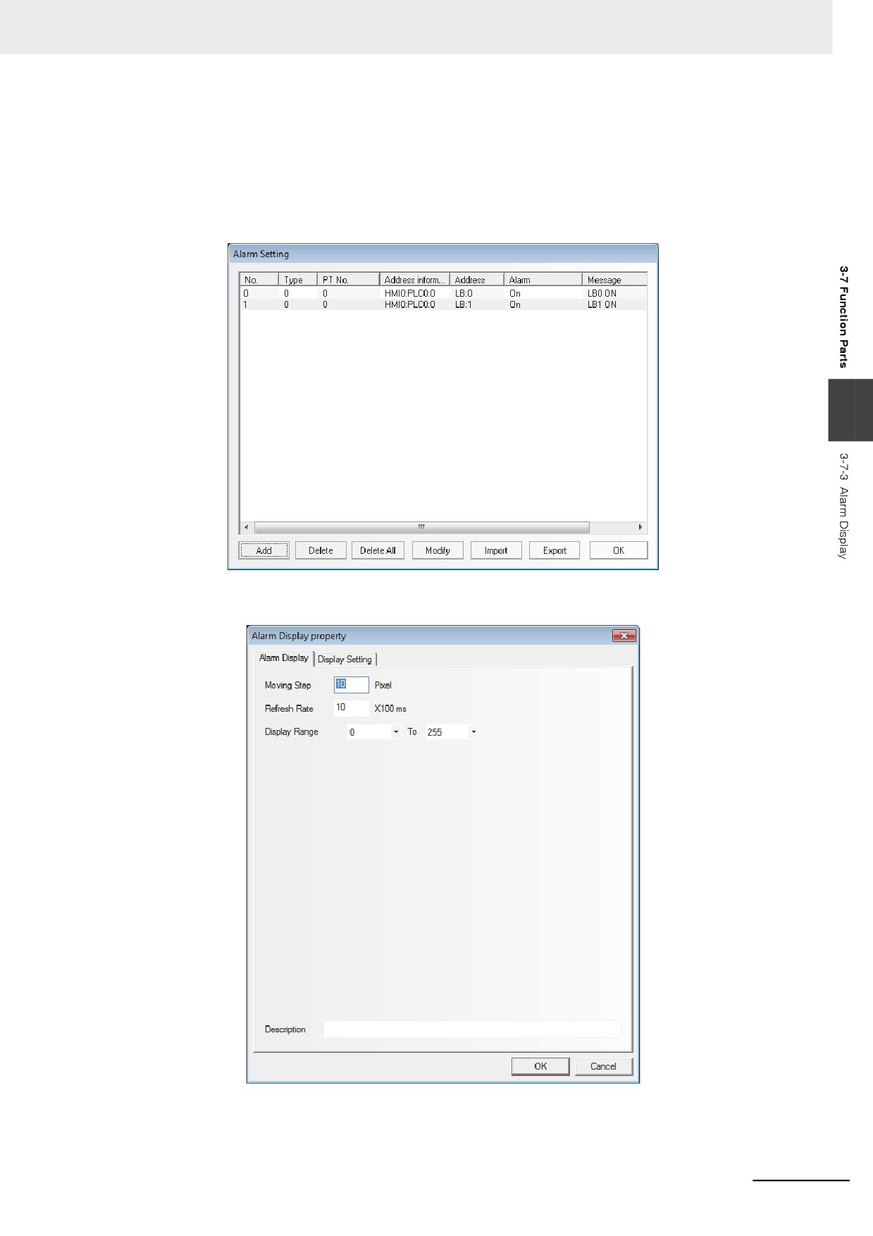
Click the [Alarm Setting] icon in [Project Database] to display the logon list of alarm setting, and
then add two pieces of alarm setting, as shown below.
3
3
Add one Alarm Display component in Frame 0.
3-211
3 Functions of NB-Designer
4
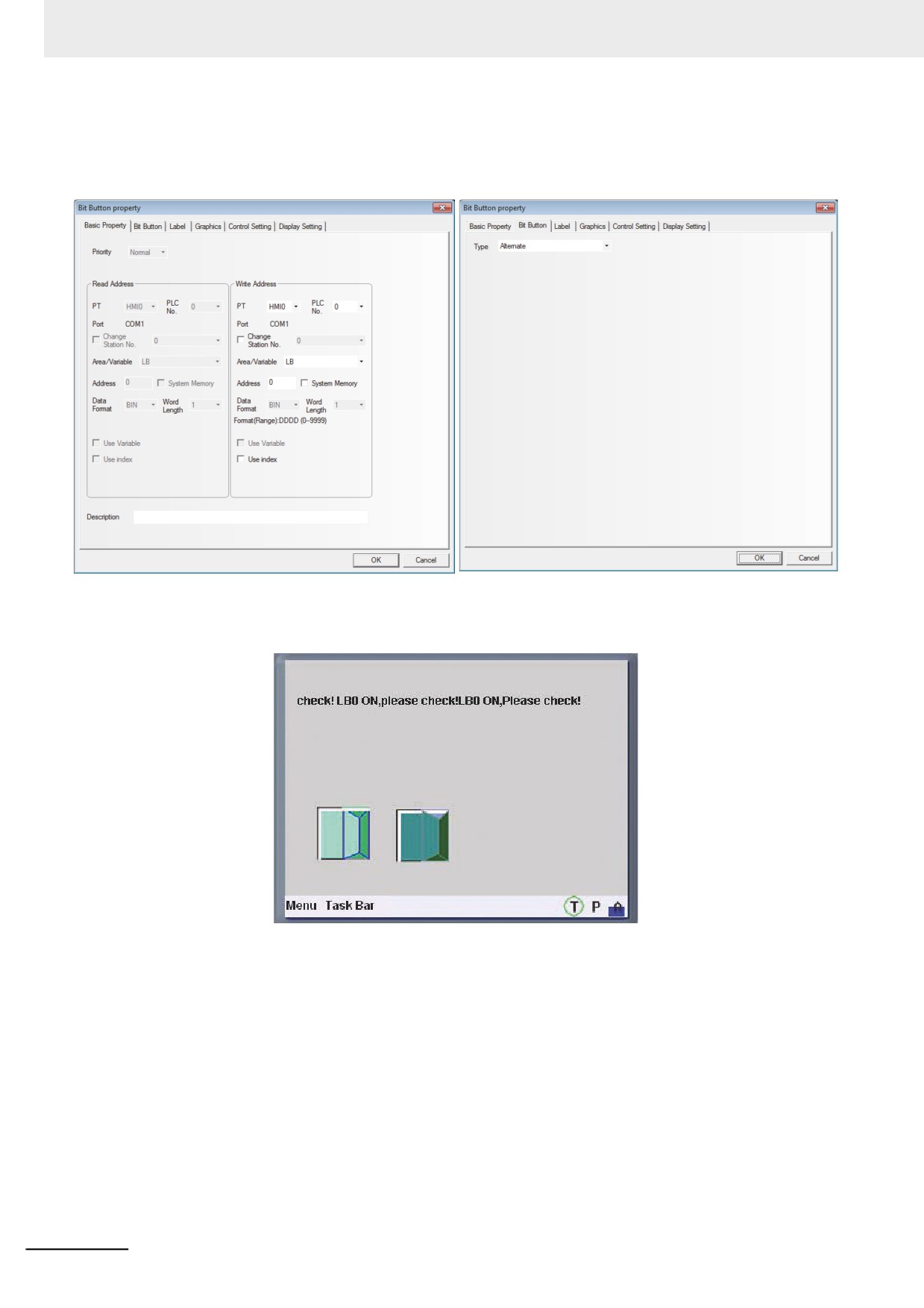
Add two Bit Switches to control the ON/OFF of LB0 and LB1 respectively, then switch the
ON/OFF state of the LB0 and LB1, the alarm setting which was registered by the procedure 2
can be switched between display and non-display by the alarm display.
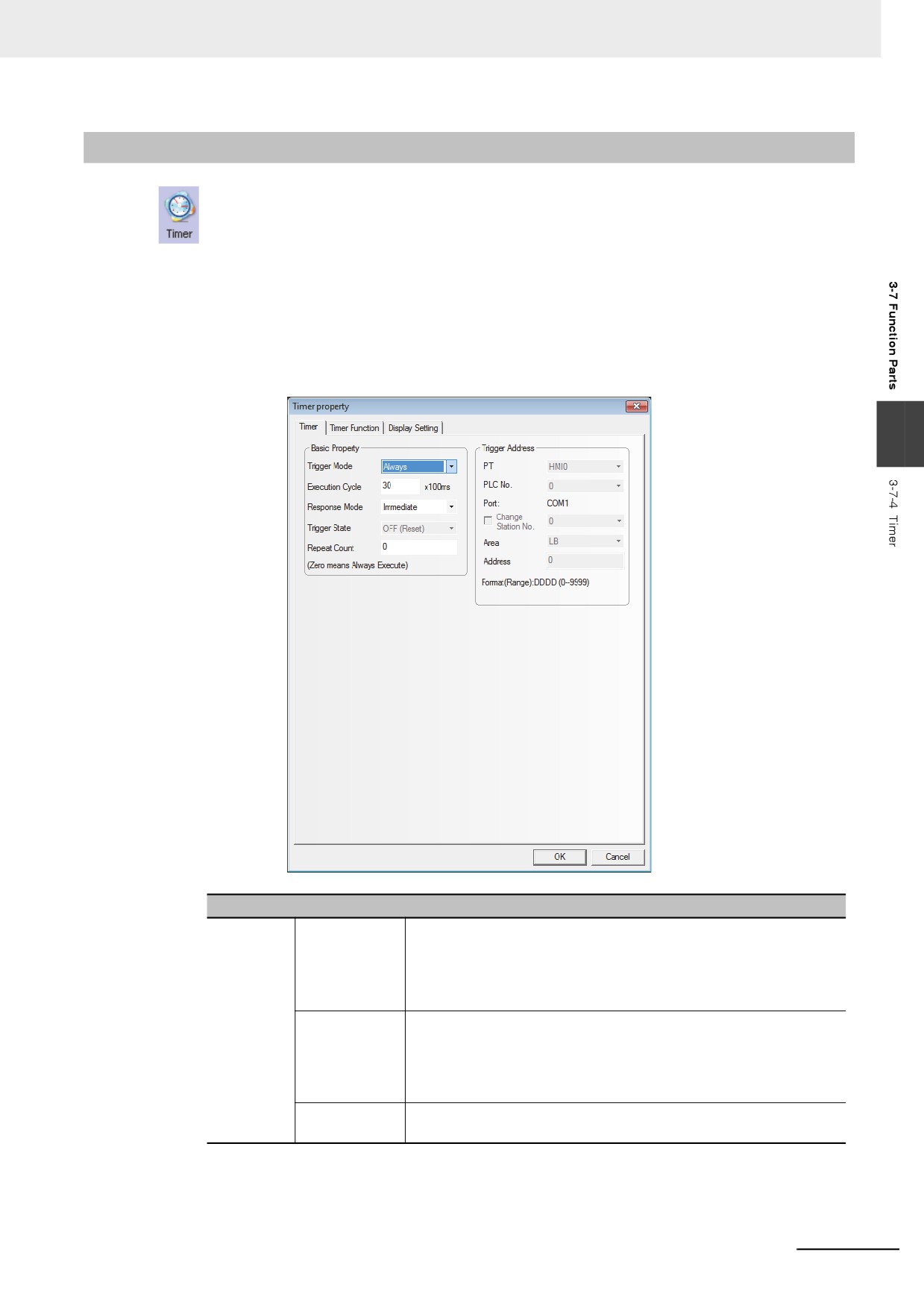
5
When saving the project files and executing the offline test after the compilation, the result will
be displayed as follows.
3-212
3 Functions of NB-Designer
3-7-4
Timer
Timer is a kind of component performing the timing. When the timing is over, it will play the
other corresponding functions such as periodical Macro instruction execution, parameter setting and
data transmission etc.
z Process of adding the Timer
1
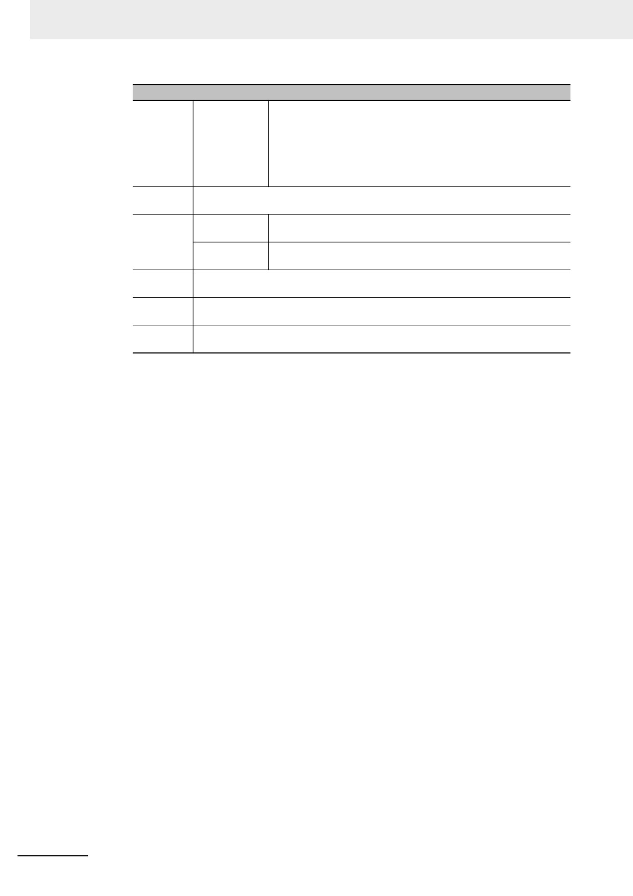
First press the Timer icon before dragging it into the screen, and go to [Timer] tab after the
[Timer Property] dialog box pops up.
3
Descriptions of Timer Properties
Trigger
Always
With this triggering mode, the timer will be triggered once it is
Mode
initialized. The timer will be operated when displaying the screen in
the timer was loaded to, and the timer will be stopped automatically
and will not be triggered any more when the number of the timer
trigger operations reaches to the value specified at “Repeat Count”.
When screen is
The timer will be operated when the timer is placed in the screen and
loading
the number of the timer trigger operations it will stop automatically
after the value set in “Repeat Count” being reached, and will not be
triggered any more. The effect of this function is almost the same as
that of “All time”.
When screen is
Function operation will be triggered once when the screen where the
unloading
timer component locates is closed.
3-213
3 Functions of NB-Designer
Descriptions of Timer Properties
Trigger
Trigger
When the address specified at [Trigger Address] matches to the
Mode
Address
status specified at [Trigger State], the triggering operates. If [Repeat
Count] is set to “0”, the triggering operation is consecutively repeated
until the trigger condition is released. After the trigger condition is
cleared once, followed by the trigger is operated for the number of
times specified at [Repeat Count], the timer will be stopped
automatically.
Execution
It refers to the timing cycle of the timer with the unit of 100 ms. The timer will perform
Cycle
functional operation once at each interval of timing cycle.
Response
Immediate
When the triggering condition is met, the function will be executed
Mode
immediately.
Delay
When the triggering condition is met, the function will be executed
after one cycle is delayed.
Trigger
When “Trigger Address” is selected, the triggering state of the memory is On or Off.
State
Repeat
It refers to the times of repeated execution after the timer is triggered. When it is “0”, the
Count
function will always be executed.
Trigger
After “Trigger Address” is selected, it needs to specify the address to be the trigger.
Address
2
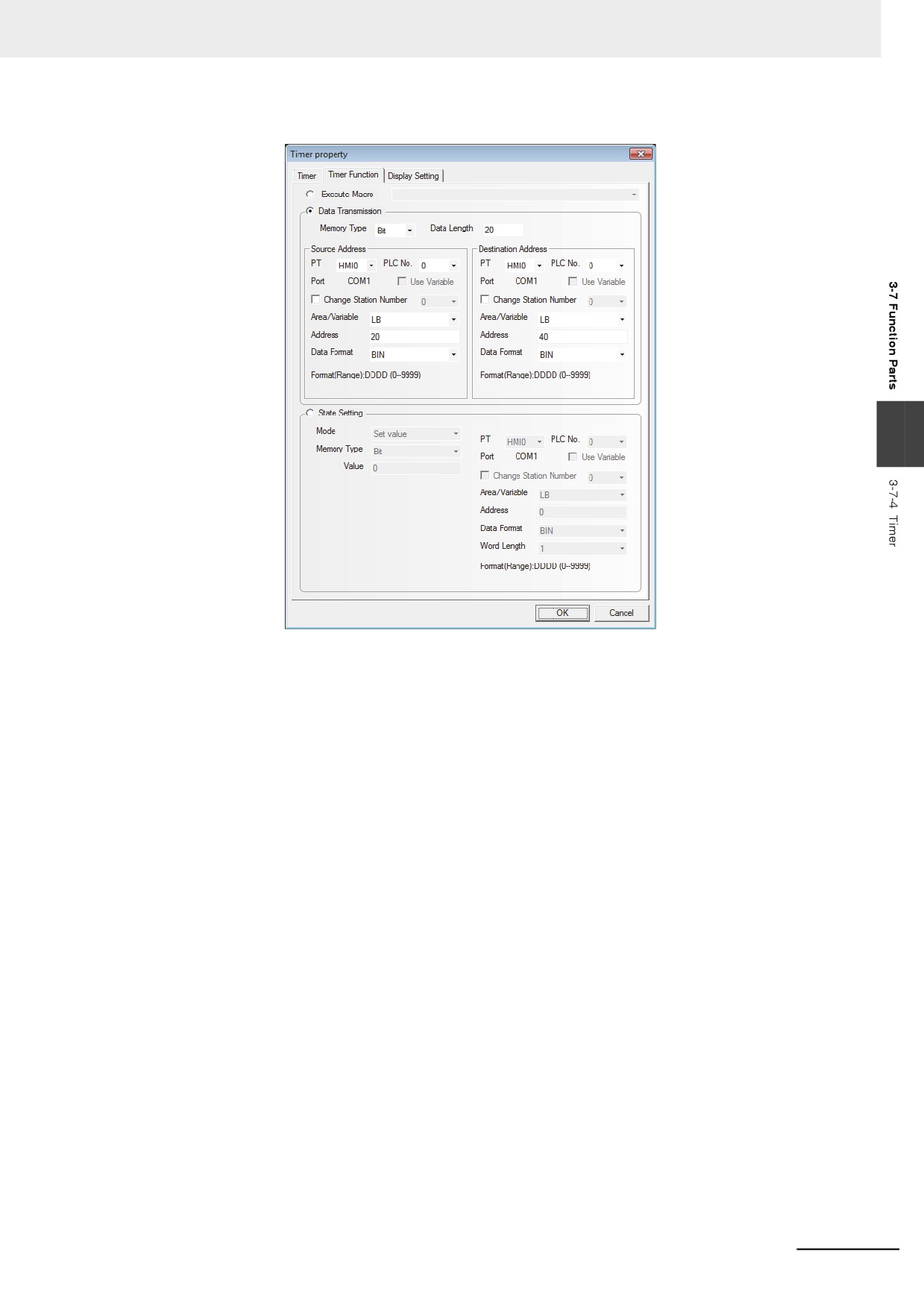
Switch to the [Timer Function] tab:
Execute Macro: The Macro code to be executed for each timing reached to the time set by the
executing cycle. (Refer to 3-9-3 Macro Triggering (Page 3-273))
Data Transmission: The data transmission will be performed. The data will be transformed
from the specified addresses as ([Source Data]) to the specified
addresses as ([Destination Address]) for each timing reached to the time
set by the executing cycle.
Source Address: Refers to the starting address that the data will be transferred from.
Destination Address: Refers to the starting destination address that the data will be transferred to.
Memory Type: Used to select among “Word” or “Bit” for the memory type to be transmitted.
3-214
3 Functions of NB-Designer
Data Length: Refers to the length of the data to be transferred.
3
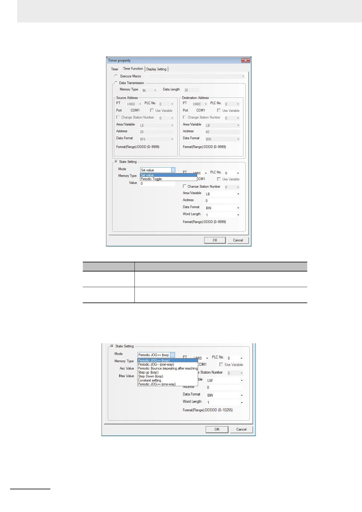
State Setting: After the time set at Execution cycle passed, when the value is written to the bit
address or word address, select the parameter.
Set Address: After the time which was set at Execution cycle passed, specify the bit address or
word address to be written.
(a) Bit Address Setting ([Memory Type] is specified to [Bit]):
3-215
3 Functions of NB-Designer
Mode: Includes Set value, Periodic Toggle, as shown below.
The detailed description of each function is as follows.
Mode
Descriptions
Set Value
After the time which was set at Execution cycle passed, specify the
value of the bit address to “0” or “1”.
Periodic Toggle
After the time which was set at Execution cycle passed, switch the
value of the bit address “0” with “1”
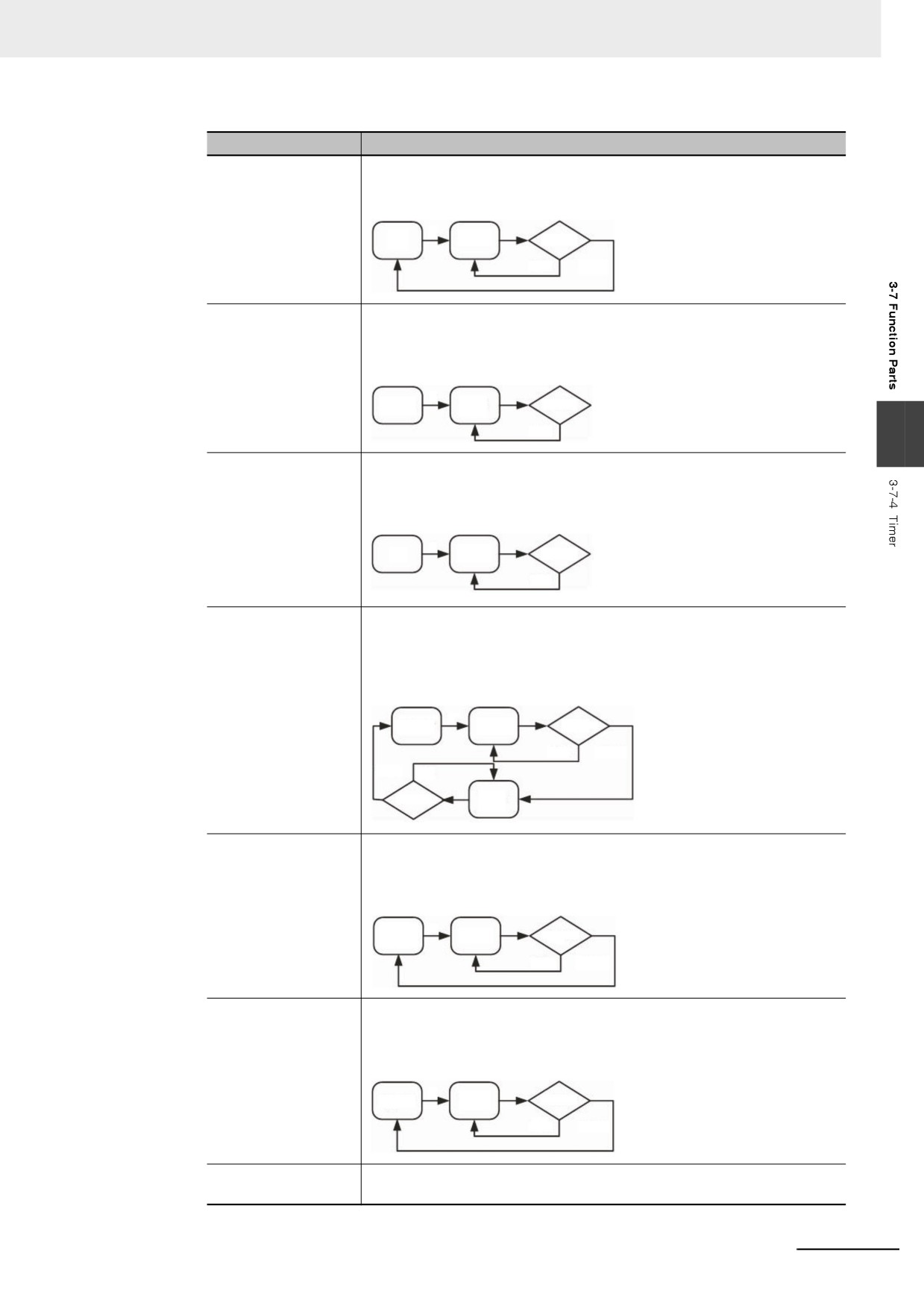
(b) Word Address Setting([Memory Type] is set to [Word]:
Mode: Periodic JOG++(loop), Periodic JOG--(one way), Periodic Bounce(repeating
after reaching), Step up(loop), Step Down(loop), Constant Setting, and Periodic
JOG++(one-way) as shown below.
3-216
3 Functions of NB-Designer
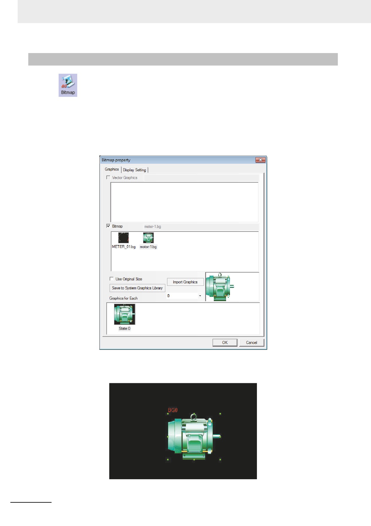
Mode
Descriptions
Periodic
This mode makes the address value of the memory for the specified word
JOG++(loop)
increase automatically by the “increment” at the interval of each “Execution
Cycle” and makes it return 0 again when “the upper limit value” is reached.
T
0
V+K
Upper
NO
YES
Periodic
This mode makes the address value of the memory for the specified word
JOG--(one-way)
decrease automatically by the “decrement” at the interval of each “Execution
Cycle” and makes it stop at the lower limit value after “the lower limit value” is
reached.
T
Upper
V-K
Lower
NO
3
Periodic
This mode makes the address value of the memory for the specified word
JOG++(one-way)
increase automatically by the “increment” at the interval of each “Execution
Cycle” and makes it stop at the upper limit value after “the upper limit value”
is reached.
T
0
V+K
Upper
NO
Periodic Bounce
This mode makes the address value of the memory for the specified word
(repeating after
increase automatically by the “step” at the interval of each “Execution Cycle”
reaching)
until to “the upper limit value”, and then makes it decrease by the “step” at
the interval of “Execution Cycle” until to the “lower limit value”, and later
makes it increase again, thus making the cycle repeated again and again.
T
Lower
V+K
Upper
NO
YES
YES NO
Lower
V-K
Step up (loop)
This mode makes the address value of the memory for the specified word
increase automatically by the “step” at the interval of each “Execution Cycle”
until to “the upper limit value”, and makes it increase again after being reset
to “the lower limit value”.
T
Lower
V+K
Upper
NO
YES
Step down (loop)
This mode makes the address value of the memory for the specified word
decrease automatically by the “step” at the interval of each “Execution Cycle”
until to “the lower limit value”, and makes it decrease again after being reset
to “the upper limit value”.
T
Upper
V-K
Lower
NO
YES
Constant Setting
The preset constant value will be written to the address of the memory for the
specified word after the “Execution Cycle” is reached.
3-217
3 Functions of NB-Designer
3-7-5
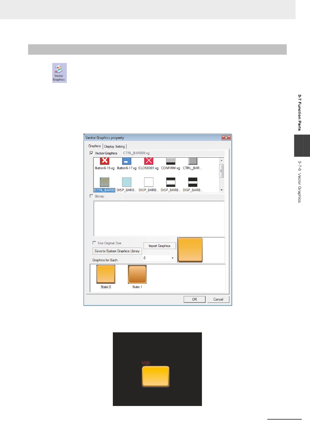
Bitmap
Bitmap component is used to call and display the bg-form graphics registered in the system
graphics library or the graphics library in Project File Window. Bitmap component is not controlled by
the memory, and doesn’t have multiple states, thus the bitmap corresponding to the graphics state
specified by you at the designing time will always be displayed. For the creation and usage of bitmap,
refer to [3-5-6 Bitmap].
1
First press the Bitmap icon, drag it to the screen, then select the bitmap you want to use, as
shown below.
2
Press the [OK] button, and then adjust the position and the size of the Bitmap in the screen, as
shown below:
3-218
3 Functions of NB-Designer
3-7-6
Vector Graphics
Vector Graphics component is used to call and display the vg-form graphics registered in the
system graphics library or the graphics library in Project File Window. The Vector Graphics component
is not controlled by the memory, and doesn’t have multiple states, thus the Vector Graphics
corresponding to the graphics state specified by you at the designing time will always be displayed. For
the creation and usage of Vector Graphics, refer to [3-5-5 Vector Graphic].
1
Press the Vector Graphics icon, drag it to the screen, then select the Vector Graphics you want
to use, as shown below.
3
2
Press the [OK] button, and then adjust the position and the size of the Vector Graphics in the
screen, as shown below:
3-219

3 Functions of NB-Designer
3-7-7
Notepad
Notepad is designed specially to provide the users with a space for the message reservation
and transmission, thus allowing the users to write any text on the PT freely. And its function is similar to
that of the drawing board.
z Process of adding Notepad
1
Press the Notepad icon, drag it to the screen, then the [Notepad Property] dialog box will pop
up.
Frame Width: Refers to the frame width of the Notepad.
Background Color: Selects the Background Color and Pattern Color.
2
Press the [OK] button to complete the setup, and adjust the position and size of the Notepad
component.
3-220
3 Functions of NB-Designer
z The combined use of Notepad with Function Keys
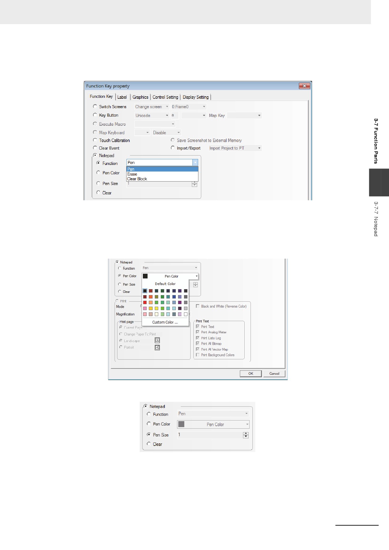
After the Notepad is placed well, you can set the Function, Pen Color, Pen Size and Clear after the
[Notepad] is selected in the Function Key tab, as shown below.
3
(a) Function
Pen: After selecting the pen, you can leave messages or make drawings in the Notepad.
Eraser: Clears the contents in the Notepad.
Clear Block: Clears the contents in the selected area of the Notepad.
(b) Pen Color: Sets the pen color, as shown below.
(c) Pen Size: Sets the thickness of pen from the available 1 (the thinnest) to 8 (the thickest), as shown
below.
(d) Clear: Clears the contents in the whole Notepad.
3-221
3 Functions of NB-Designer
z Create a Notepad
1
Makes Frame 0 as the Note pad screen. Of course you can make the other screen as the Note
pad screen. And later you just need to drag the Notepad component to the screen.
2
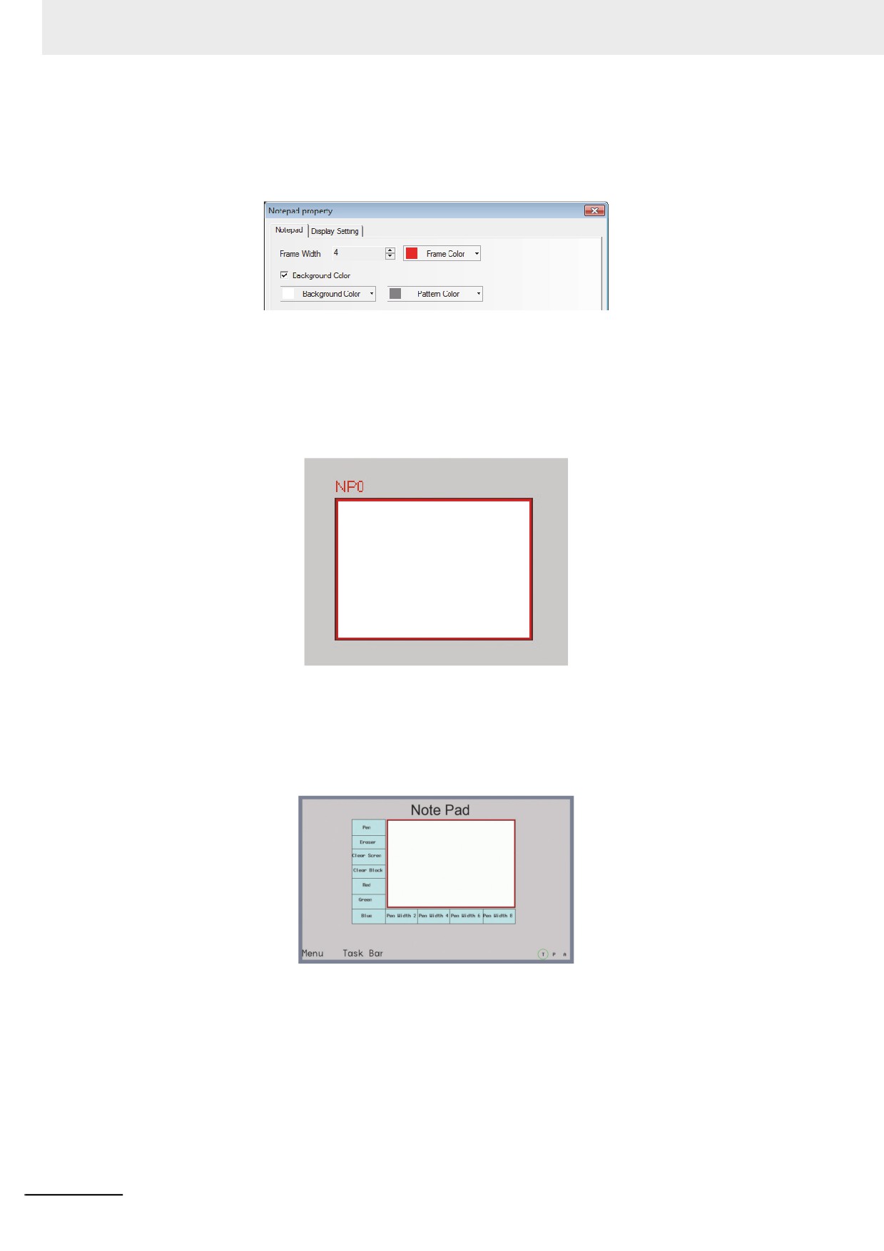
Firstly set the Properties of the Notepad component, as shown below.
Frame Width: Select 4 here from the range of 1 to 16.
Frame Color, Background Color and Pattern Color: Select the colors you want to use here.
3
Then adjust the screen to the required size, as shown below.
4
Later add several Function Keys in the left and bottom of the Notepad component respectively,
i.e. select Function Keys FK0, FK1, FK2 and FK3 to be as Pen, Eraser, Clear Block and Clear
Screen respectively, select the Function Keys FK4, FK5, and FK6 to be the Pen Colors of Red,
Green and Blue respectively, and select the Function Keys FK7, FK8, FK9 and FK10 to be the
Pen Sizes of 2, 4, 6 and 8 respectively, as shown below:
3-222
3 Functions of NB-Designer
5
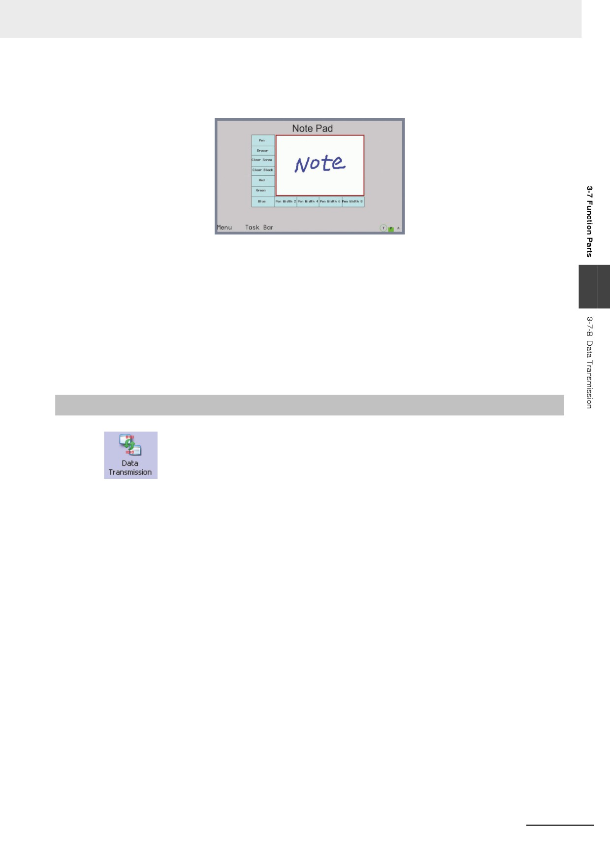
[Save] and [Compile] the project files and execute [Offline Test] and result in the display as
follows.
The system reserves the following areas for the system memory:
• LB9020 to LB9032: [Pen], [Eraser], [Clear Block],
• LB9030 to LB9032: pen size,
3
• LW9006 : operation mode of Notepad,
• LW9007 : pen size
• LW9008 : color of pen selecting among 256 colors.
For the details, refer to 3-11 Address of System Memory (Page 3-328).
Note 1
Each PT can only use one Notepad component. If there are more than one Notepad components, an error
occurs at the compilation.
2
The data in the Notepad will not be saved, i.e. be lost, when the power of PT is OFF.
3-7-8
Data Transmission
Data Transmission component can make the data in the specified memory address
transferred to the other memory address. Data Transmission can be triggered by the manual touching
method or the state change of the specified address.
3-223
3 Functions of NB-Designer
z Process of adding Data Transmission
1
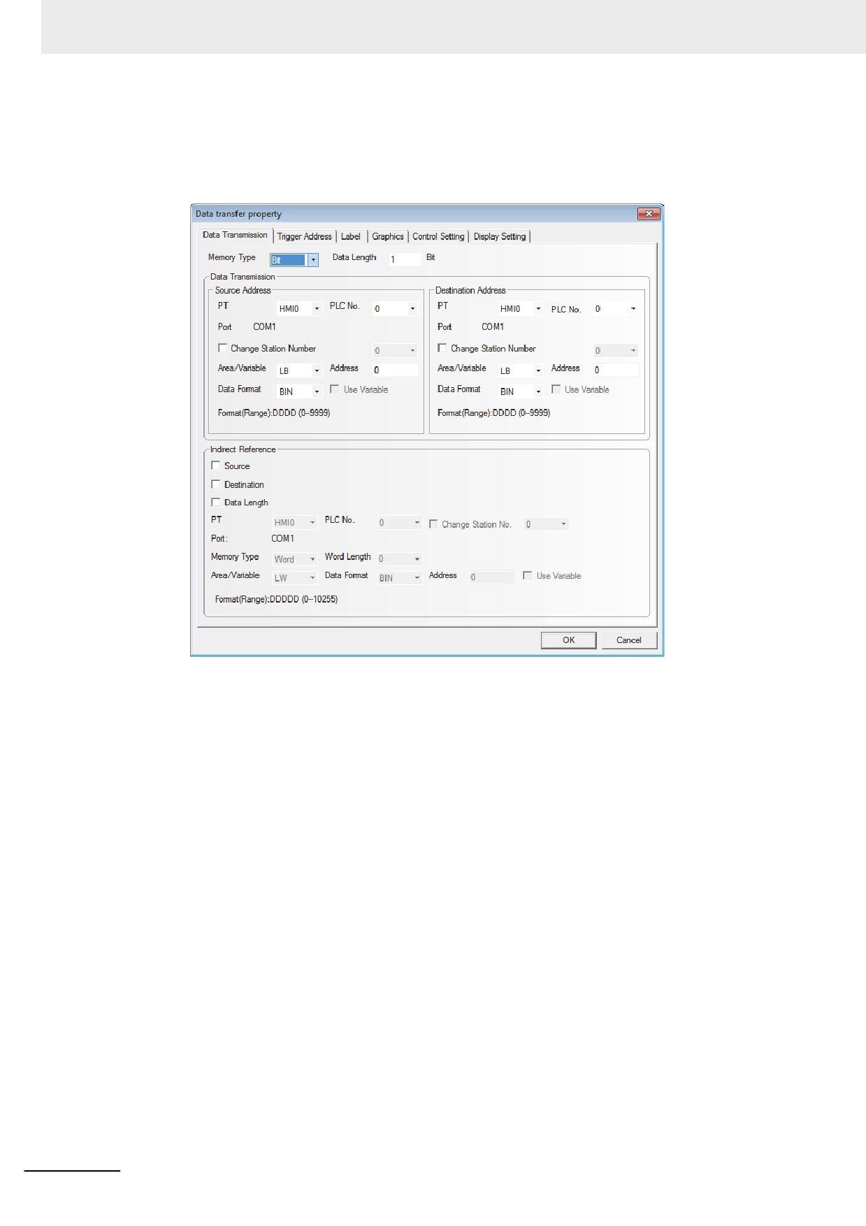
Drag the Data Transmission icon to the screen after it being pressed, then the [Data
Transmission Property] dialog box will pop up.
Memory Type: The Memory Type which is transmitted should be selected among [Bit] (bit
data) or [Word] (word data).
Data Length: The number of data transferred by the Data Transmission component. When the
Memory Type is Bit or Word, the units are “bit” or “word” respectively. A
maximum 2000 partitions of data can be specified.
Source Address: Sets the source address of the transferred data.
Destination Address: Sets the destination address of the data transmission.
Indirect Reference: Set this parameter when setting indirectly the source address, destination
address, and data length.
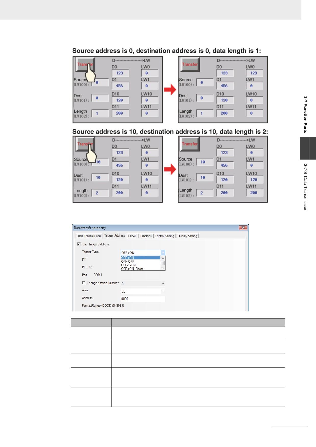
Take the following settings as example, i.e. the source address, destination address and data
length use the Indirect Reference.
After setting the source address type to “D memory” and making the source address offset
controlled by the LW100, set the destination address type to “LW memory” and make the
destination address offset and the data length controlled by the LW101 and LW102
respectively.
3-224
3 Functions of NB-Designer
3
2
Set the [Trigger Address].
Trigger Type
Descriptions
OFF˘ ON
When the state of the specified address is switched from OFF to ON, the Data
Transmission component will be triggered to perform the transmission.
ON˘ OFF
When the state of the specified address is switched from ON to OFF, the Data
Transmission component will be triggered to perform the transmission.
OFF¯˘ ON
When the state of the specified address is changed, the Data Transmission
component will be triggered to perform the transmission.
OFF˘ ON, Reset
When the state of the specified address is switched from OFF to ON, the Data
Transmission component will be triggered to perform the transmission. At the
same time with the transmission, the specified address will be turned OFF.
ON˘ OFF, Reset
When the state of the specified address is switched from ON to OFF, the Data
Transmission component will be triggered to perform the transmission. At the
same time with the transmission, the specified address will be turned ON.
3-225
3 Functions of NB-Designer
3
Make settings in the [Label], [Graphics] and [Control Setting] tabs by using the similar method
for the components mentioned above.
4
Press the [OK] button to complete the setup, and adjust the position and size of the Data
Transmission component.
3-7-9
Freeplotting
The Freeplotting component is based on the data in the memory, and you can use it to
draw the corresponding graphics by the pixel point in the PT.
z Freeplotting Component Property
1
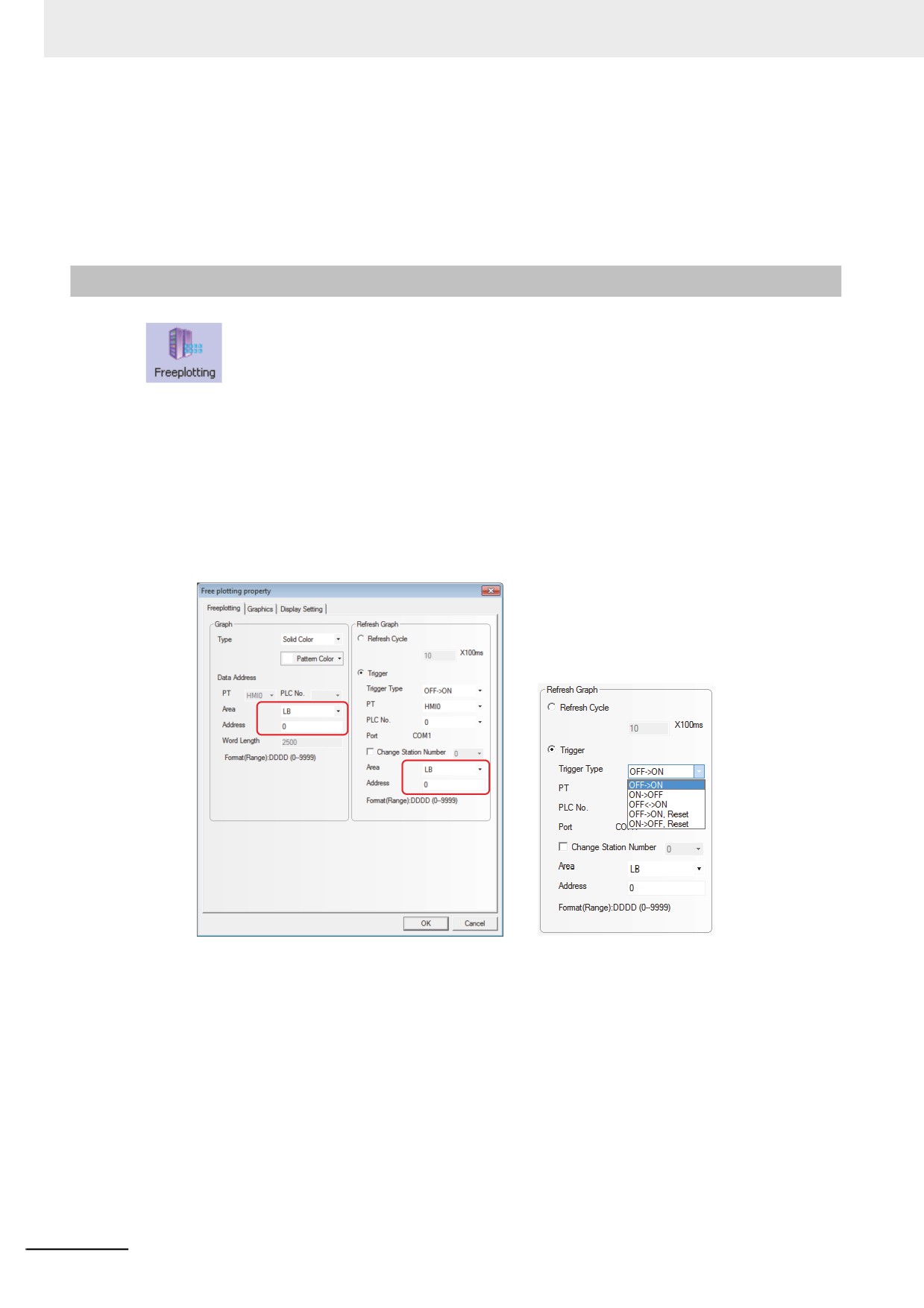
When selecting [Solid Color] for the Type (drawing graphics using the bit memory)
Set the component size to 50×50, the memory address to LB0, the pattern color to red and the
values of 2500 memories (i.e. LB0 to LB2499) to be read by PT. Then when the memory value
is 1, the pixel point of the component corresponding to the communication address which
stored the values will be applied by red color.
3-226
3 Functions of NB-Designer
2
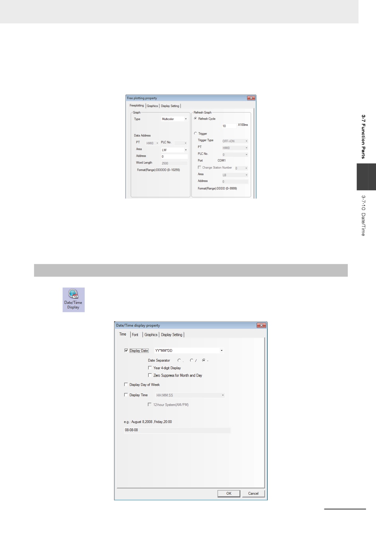
Multicolor is selected for Type (Draw graphics using word memory.).
Set the component size to 50×50, the memory address to LW0, and the values of 2500 memories
(i.e. LW0 to LW2499) to be read by PT. Then the pixel point of the component corresponding to the
communication address which stored the values will be drawn into the corresponding 65536 true
color according to the actual value read from the memory.
3
3
There are two refreshing methods for the components.
Refresh Cycle: The graphics are updated at a certain period. The minimum unit to update the
graphics can be set at 100ms.
Trigger: When the status of the bit address specified with [Trigger] matches to the condition
specified with [Trigger Type], the graphics are updated.
3-7-10
Date/Time
The Date/Time component can display the value of the internal RTC clock of the PT in the set
format.
3-227
3 Functions of NB-Designer
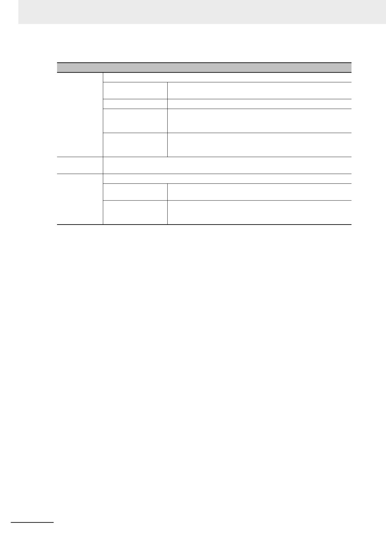
z Date/Time Component Property
Descriptions of Date/Time Component Property
Display Date
Sets whether to display the date or not.
Date Format
There are four formats available, where DD, MM and YY refer to the
date, month and year respectively.
Date Separator
Three formats are available. (e.g. 2011.06.24)
Year 4-digit Display
Displays 4-digit included in the year after this option being selected.
For example: “2011 Year” will be displayed as “2011” or “11” after this
option is checked or not checked respectively.
Zero Suppress for
Clears zero included in the date and month after this option being
Month and Day
selected. For example: “June” will be displayed as “6” or “06” after this
option is checked or not checked respectively.
Display Day of
Sets whether to display the week or not.
Week
Display Time
Sets whether to display the time or not.
Time Format
There are 2 formats available, where HH, MM and SS refer to the
hour, minute and second respectively.
12-hour
The time will be displayed in 12-hour format after this option is
System(AM/PM)
checked. For example: “3 PM” will be displayed as “3:00 PM” or
“15:00” when this option is checked or not checked respectively.
The Date/Time component can only read the time of the internal RTC of the PT, but not modify the
time. If the time of the internal RTC of the PT needs to be modified, you can calibrate the system time
by using the system setup screen of the PT or modifying the values of system special memories
LW10000 to LW10006.
3-228
3 Functions of NB-Designer
3-7-11
Indirect Shape
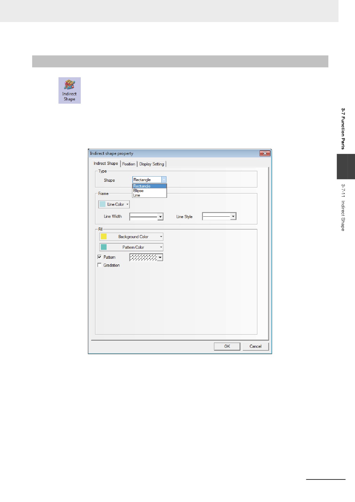
The Indirect Shape component can modify the positions and sizes of the rectangle, ellipse or
line by changing the value of the memory.
z Indirect Shape Properties
1
Indirect Shape tab
3
Type: Sets the shape type from the available types of the Rectangle, Ellipse and Line.
Frame/Line: Sets the Line Color, Line Width and Line Style for the rectangle and ellipse, and
line.
Fill: Sets the fill color and the fill style for the rectangle and ellipse.
3-229
3 Functions of NB-Designer
2
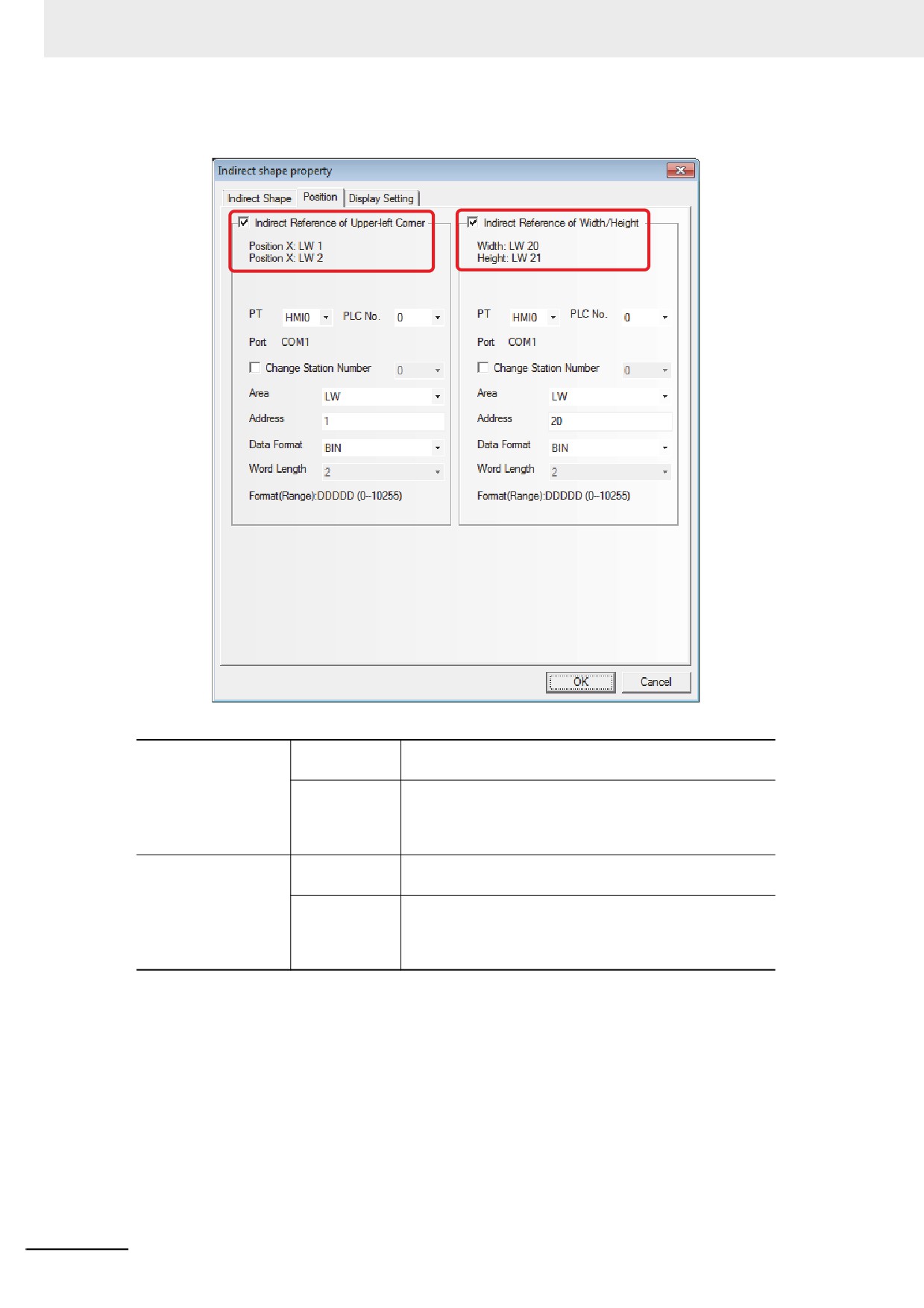
Position
The descriptions of the specific Properties are as follows:
Indirect Reference of
Unchecked
Position X and Position Y of the Indirect Shapeics are the
Upper-left Corner
constants.
Checked
Position X and Position Y of the Indirect Shapeics are the
indirect reference.
Position X = First address of the set memory,
Position Y = First address of the set memory + 1
Indirect Reference of
Unchecked
The Width and Height of the Indirect Shapeics are the
Width/Hight
constants.
Checked
The Width and Height of the Indirect Shapeics are the
indirect reference.
Width = First address of the set memory,
Height = First address of the set memory + 1
3-230
3 Functions of NB-Designer
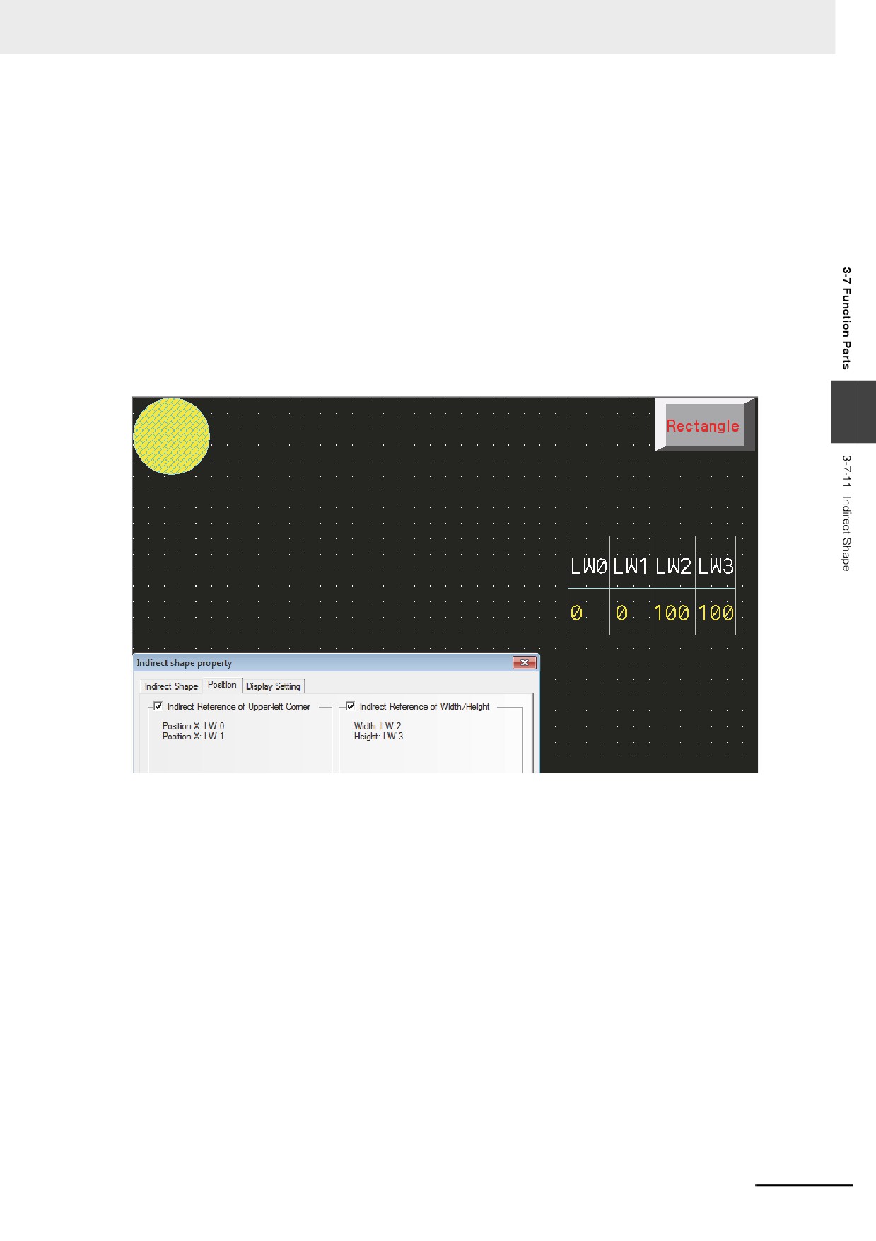
Example of creating Indirect Shape
1
Set and place Indirect Shape (ellipse) components as follows:
•
[Shape] : Ellipse
• top address of [Indirect Reference of Upper-left Corner] : LW0
• top address of [Indirect Reference of Width/Height] : LW2
Storing the values as follows, the effect is shown as below:
• LW0 (Coordinate position of X in upper-left corner) : 0
• LW1 (Coordinate position of Y in upper-left corner) : 0
• LW2 (Width) : 100
• LW3 (Height) :100
3
3-231
3 Functions of NB-Designer
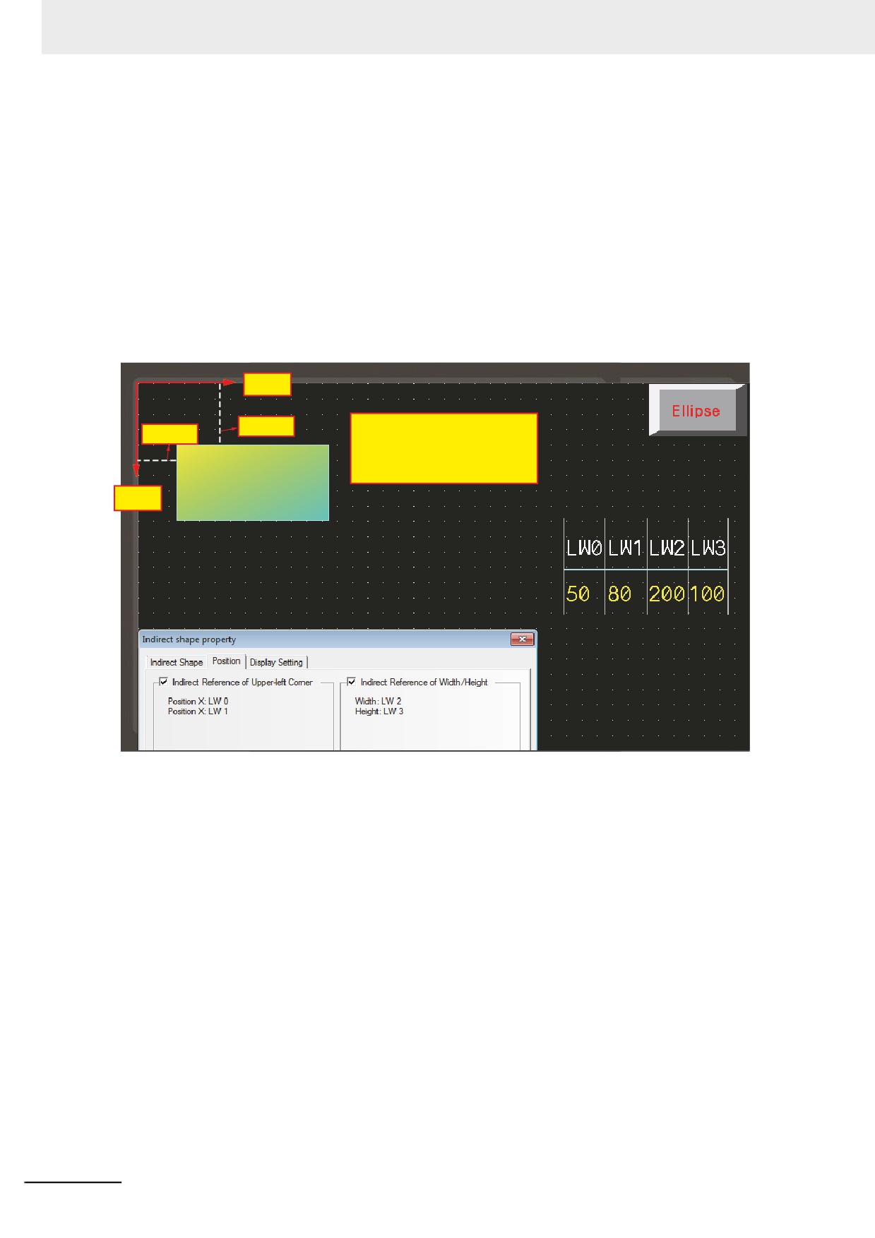
2
Set and place Indirect Shape (Rectangle) components as follows:
•
[Shape] : Rectangle
• top address of [Indirect Reference of Upper-left Corner] : LW0
• top address of [Indirect Reference of Width/Height] : LW2
Storing the values as follows, the effect is shown as below:
• LW0 (Coordinate position of X in upper-left corner) : 50
• LW1 (Coordinate position of Y in upper-left corner) : 80
• LW2 (Width) : 200
• LW3 (Height) :100
X-axis
80 pixels
Screen cartesian system:
50 pixels
Origin in the upper left corner.
X-axis growth to the right.
Y-axis growth to the down.
Y-axis
3-232