OMRON NB-Designer OPERATION MANUAL (NB-series, 2020) - page 13
3 Functions of NB-Designer
3
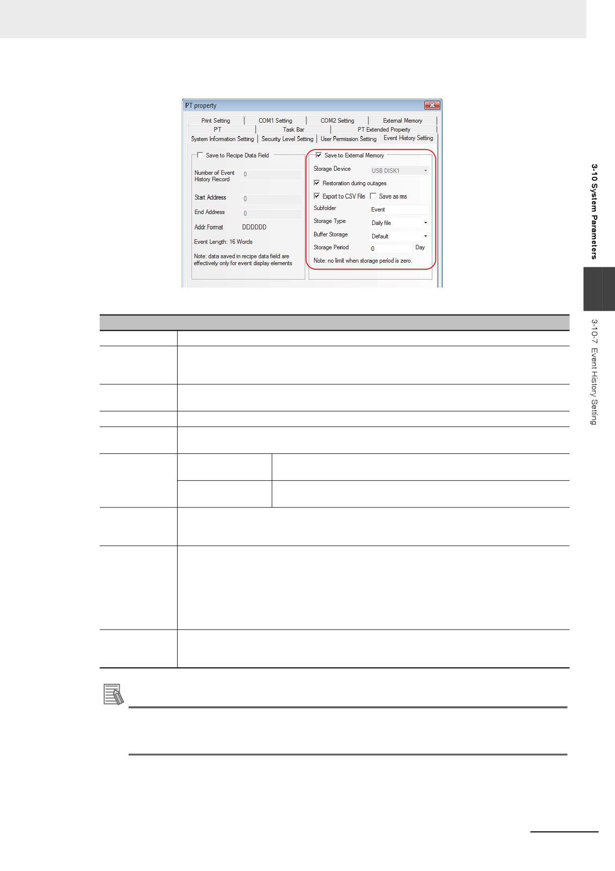
Descriptions of Historical Events Storage
Storage Devices
USB 1
Restoration
When the NB unit is restarted by the power interruption, if this option is checked, 1024 items
during outages
of the event history which were archived until the power interruption can be displayed in the
Event.
Export to CSV
Exports the Event History information in CSV format to the external memory. The path for
File
storing this CSV file is “/event/subfolder name/file name”.
Save as ms
Makes the data sampling time accurate to the millisecond and records it into the CSV file.
Subfolder
Sets the subfolder name of the external memory where the CSV file will be stored. Although
the default name is “Event”, the user can modify it.
Storage Type
Daily File
Stores the Event History information by day and records them into the
CSV file named in “yyyy mmdd” format.
Single File
Stores the Event History information by the piece and records them
into the CSV file with the name of “Subfolder Name”.
Buffer Storage
When the data size written to the external memory reaches to the specified buffer size, the
writing is performed only once. “Default” means unbuffered, i.e. the writing operation will
immediately be performed once the data is generated.
Storage Period
Sets the upper limit for the event history with the unit of “Day” for Daily File and “Record” for
Single File. When the [Daily File] is selected, the file will be named in “yyyy mmdd” form and
the Storage Period is the upper limits of the number of CSV files in this path; if the Storage
Period is exceeded, the oldest file will be deleted. If the [Single File] is selected, the file will be
named in “Subfolder Name” form, the Storage Period is the upper limit of the records archived
in the file; the archived records are reached to the Storage Period, the storage will not be
continued. (yyyymmdd refers to the execution date.)
Additional
An operation on an event history file is executed when the conditions set in this section are
information
satisfied and an event occurs. A file operation may not be executed in some circumstances:
status of conditions and event generation timing.
Additional Information
A delete operation on an event history file is executed when the conditions set in this section are
satisfied and an event occurs. A file delete operation may not be executed in some circum-
stances: status of conditions and event generation timing.
3-323
3 Functions of NB-Designer
3-10-8
COM1/COM2 Setting
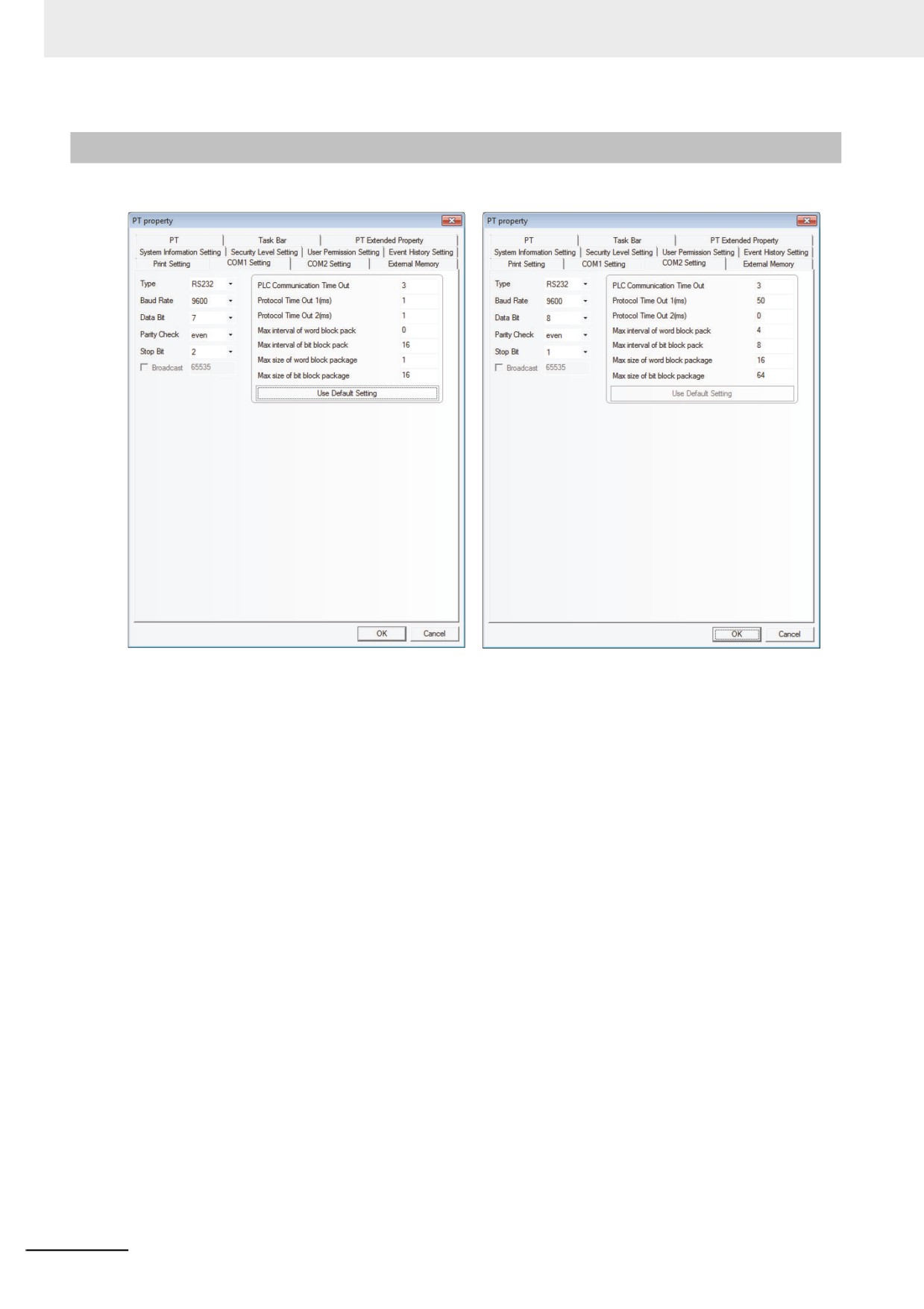
There are [COM1 Setting] and [COM2 Setting] here because NB Unit has 2 serial ports. You can make
the connection to 2 PLCs through these two serial ports.
Type: Selects the communication method between the PT and PLC from RS-232, RS-422 and RS-485.
Baud Rate, Data Bit, Parity Check and Stop Bit: Selects the communication parameters matching
the PLC.
PLC Communication Time Out: Determines the time that the PT needs to wait for the PLC response.
When the delay time of communication between PLC and the PT exceeds the time expressed by the
timeout constant, the system information “PLC No Response” will be displayed in the PT. Generally,
the timeout constant is set automatically during the PLC model selection, and doesn’t need to
be modified by the user.
Protocol Time Out: Refers to the protocol timeout, which is set automatically during the PLC
selection and doesn’t need to be modified.
Max interval of word block pack, Max interval of bit block pack, Max size of word block package
and Max size of bit block package: The PT will automatically collect all the PLC data with the
consecutive addresses and send one read command to read these data, thus improving
communication efficiency and reducing the response time substantially. Max size of word block
package and Max size of bit block package set the maximum numbers of bit memory and word
memory that can be read consecutively. These numbers are generally set automatically during the PLC
selection and don’t need to be modified by the user.
If these PLC data without the consecutive addresses, the PT will send the separate commands to read
them, i.e. a lot of read commands are needed to read these data. Therefore, we allow to modify the
intervals through the Max interval of word block pack and Max interval of bit block pack. When the
2 address intervals exceed the settings, they will be divided into 2 data packages to be read, otherwise
they will be combined into 1 package. Doing this allows reducing the number of the communications
package and improving the communications efficiency.
3-324
3 Functions of NB-Designer
For example:
As shown below, for the reading of data stored in DM20 to DM29, when the PLC data package is set to
0, the system will use 3 read-commands to read these data respectively. While when “Max interval of
word block pack” is set to 1, it just needs 1 command to read these data. Generally speaking, the time
spent for reading extra 2 addresses (DM23 and DM25) is far less than the time spent for reading 2 data
package, thus reducing the time needed for the communication significantly.
DM20
DM21
DM22
DM24
DM25
DM27
3
DM28
DM29
3-10-9
External Memory
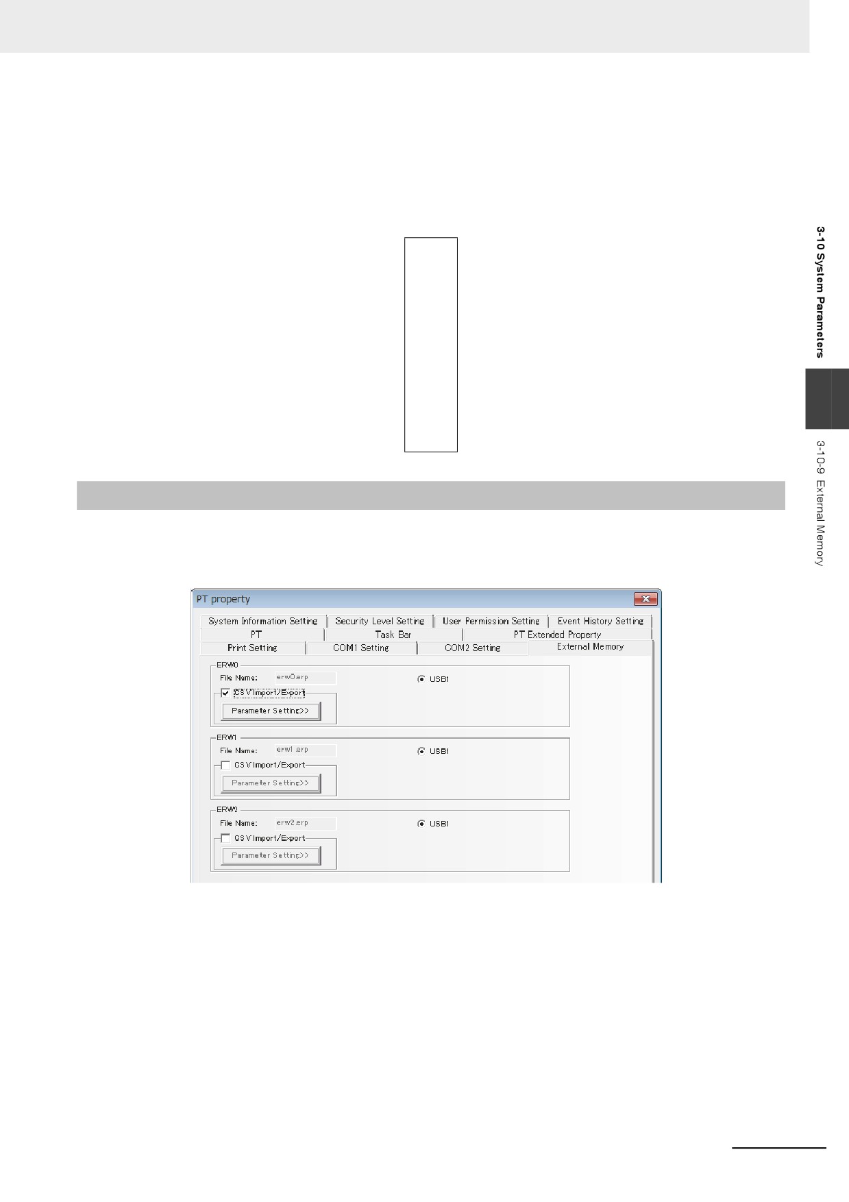
The [External Memory] tab allows checking the ERW0, ERW1, and ERW2 areas which were defined as
specific storage areas for the external memory.
The data in ERW will be stored into the specified external memory with “erp” as the file format and the
storage path of “/exmem/erwx.erp”. (x = 0, 1, 2)
•
[CSV Import / Export]
Reads and writes data into the ERW area by using a file in ".csv" format. CSV files are stored in
"/exmem/[Subfolder]/ERWx_y.csv" (x=0, 1, 2, y=0 to 511).
•
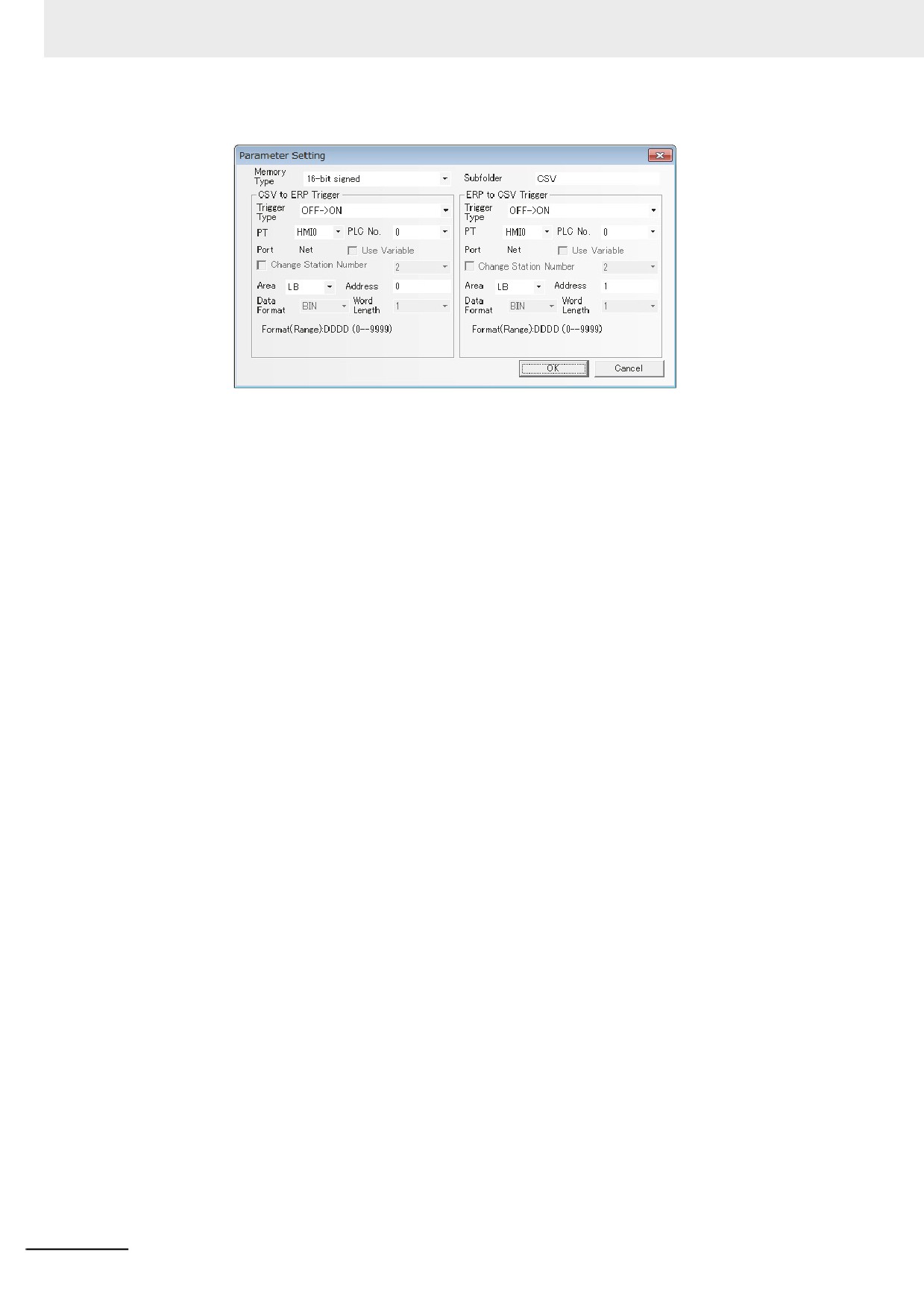
[Parameter Setting]
Makes settings for converting a file in ".csv" format into ".erp" formt.
3-325
3 Functions of NB-Designer
•
[Memory Type]
Sets a data type in the CSV file. The set data type is used to read and write values.
•
[Subfolder]
A subfolder name on the external memory where the CSV file will be stored.
•
[CSV to ERP Trigger]
Make settings for writing the data in CSV file into the ERW area by reading data from a file in ".csv"
format and writing it into a file in ".erp" format.
Whether CSV is currently being converted to ERP can be checked by LB9231.
While this function is in progress, even when the conversion conditions are met, it will be ignored.
•
[ERP to CSV Trigger]
Make settings for writing the data in the ERW area into the CSV file by reading data from a file in
".erp" format and writing it into a file in".csv" format.
Whether ERP is currently being converted to CSV can be checked by LB9221.
While this function is in progress, even when the conversion conditions are met, it will be ignored.
•
[Trigger Type]
Detects the change in address that triggers the conversion.
•
[Other Settings]
For PLC No. and address settings, refer to 3-5-10 Basic Properties of Component (Page 3-75).
3-326
3 Functions of NB-Designer
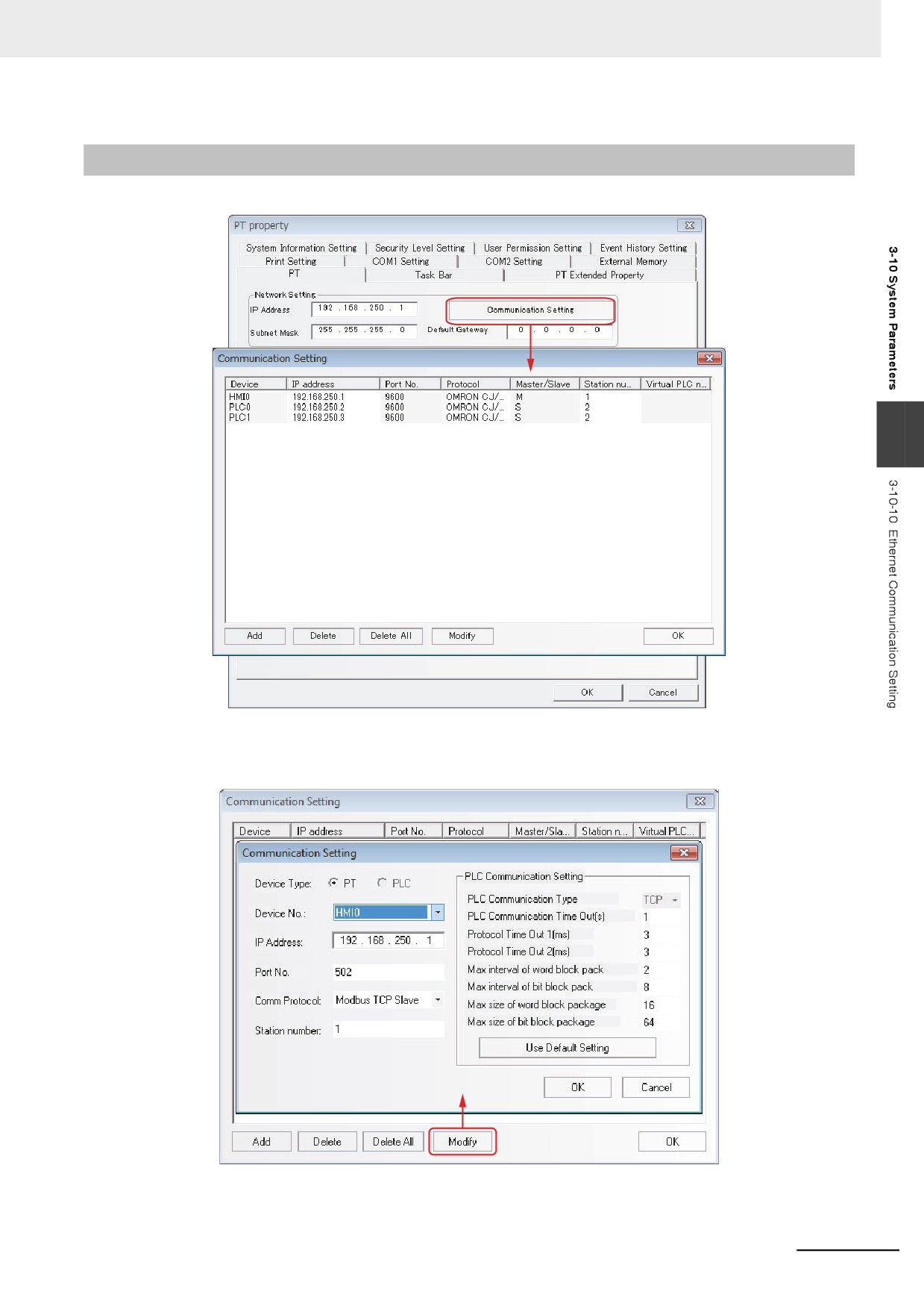
3-10-10 Ethernet Communication Setting
3
The “Communication Setting” option is used to make the “Communication Setting” for the Ethernet
communication, i.e. to configure the Ethernet communication protocol and set some related
communication parameters.
3-327
3 Functions of NB-Designer
3-11 Address of System Memory
The system reserves some addresses of Local Word (LW), Local Bit (LB), Nonvolatile Local Word (LW)
for the special purposes, and the user must use these memory addresses according to the related
descriptions.
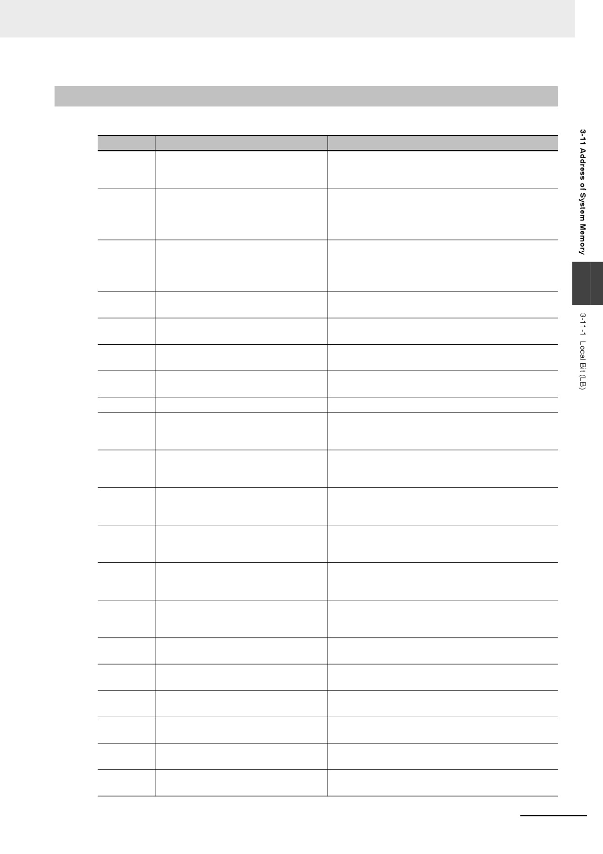
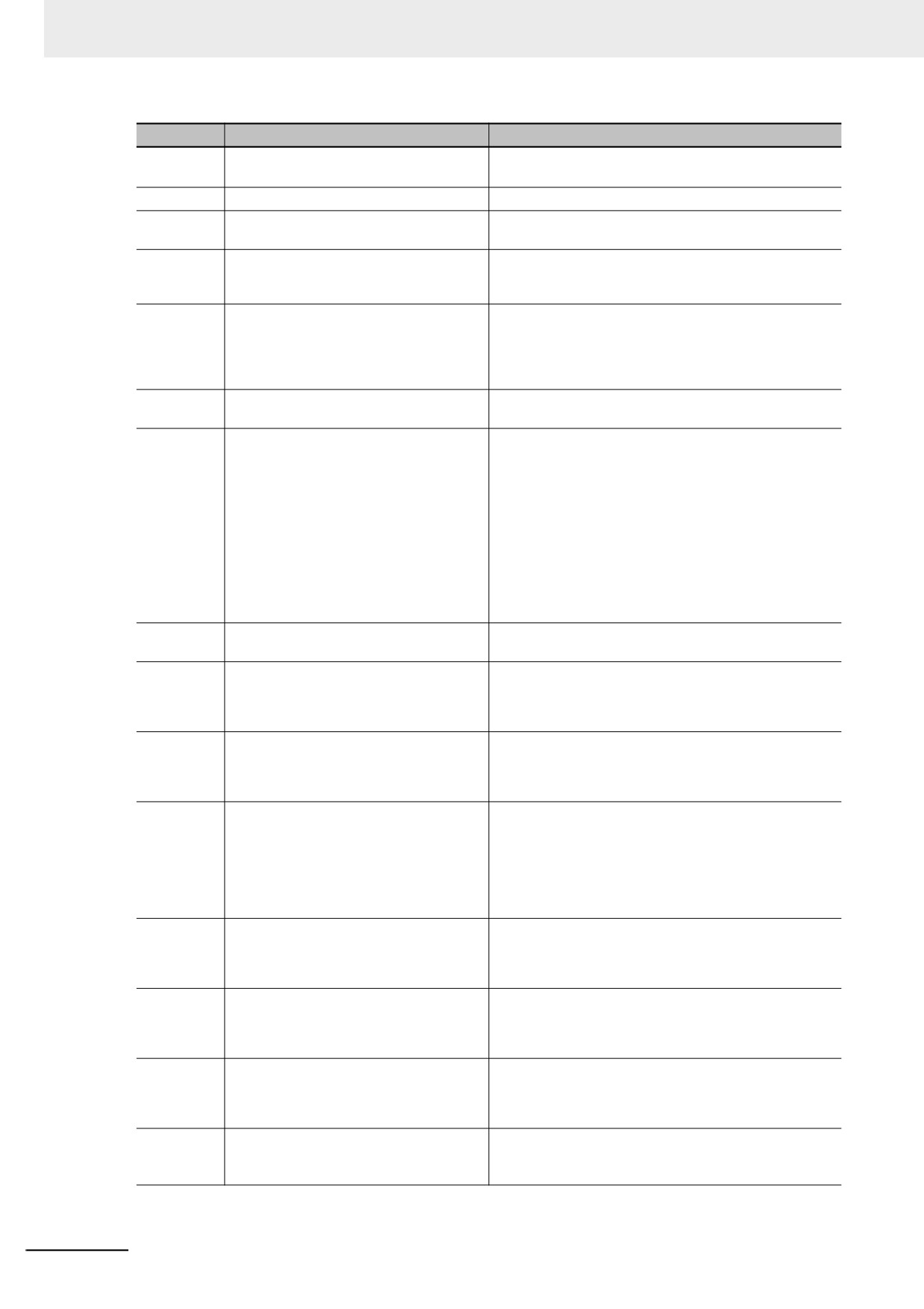
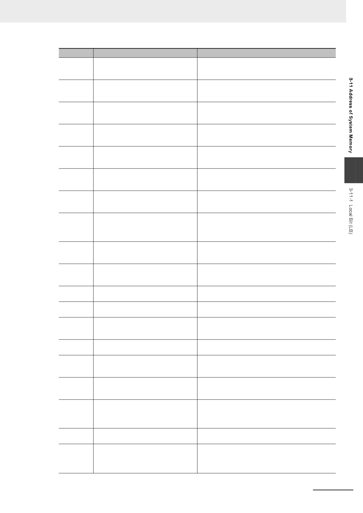
• Local Bit (LB): The reserved range is from LB9000 to LB9999.
• Local Word (LW): The reserved range is from LW9000 to LW9999.
• Nonvolatile Local Word: The reserved range is from LW10000 to LW10255.
These ranges include the read area for the system to notify of its status and the write area for the users
to perform some control to the system.
Descriptions of internal BIT memory:
LB: Refers to the local bit address of PT, which can’t be retained when power is OFF.
RB: Refers to the absolute address of bit address saved in the recipe memory that is stored in the flash
memory, which can be retained when the power is OFF. Even if the battery is dead in PT, the data
stored in the recipe memory will not be lost.
RBI: Refers to the index address of bit address saved in the recipe memory that is stored in the flash
memory, which can be retained when the power is OFF. Even if the battery is dead in PT, the data
stored in the recipe memory will not be lost.
LW.B: Refers to the bit address corresponding to the local word address of PT, which can’t be retained
when the power is OFF.
FRB: Refers to the absolute address of bit address saved in flash memory, which can be retained when
the power is OFF. When the battery is dead in PT, the data saved in flash memory will not be affected,
but the number of write operations in flash memory is limited.
FRBI: Refers to the index address of bit address saved in flash memory, which can be retained when
the power is OFF. When the battery is dead in PT, the data saved in the flash memory will not be
affected, but the number of write operations in flash memory is limited.
Descriptions of internal WORD memory:
LW: Refers to the local word address of PT, which can’t be retained when power is OFF.
RW: Refers to the absolute address saved in the recipe memory that is stored in the flash memory,
which can be retained when the power is OFF. Even if the battery is dead in PT, the data stored in the
recipe memory will not be lost.
RWI: Refers to the index address saved in the recipe memory that is stored in the flash memory, which
can be retained when the power is OFF. Even if the battery is dead in PT, the data stored in the recipe
memory will not be lost.
FRW: Refers to the absolute address of word address saved in flash memory, which can be retained
when the power is OFF. When the battery is dead in PT, the data saved in flash memory will not be
affected, but the number of write operations in flash memory is limited.
FRWI: Refers to the index address of word address saved in flash memory, which can be retained
when the power is OFF. When the battery is dead in PT, the data saved in the flash memory will not be
affected, but the number of write operations in flash memory is limited.
ERW0-ERW2: Refers to the recipe word addresses saved in the external memory, which can be
retained when the power is OFF. When the battery is dead in PT, the data saved in the external
memory will not be affected.
Note RB and RW point to the same area. For example, RB5.0 to RB5.F and RW5 map the same area, i.e.
RB5.0 is the Bit0 of RW5. But LB and LW map different areas, and the addresses pointed by them in the
memory are different.
3-328
3 Functions of NB-Designer
3-11-1
Local Bit (LB)
Addresses
Descriptions
Comments
9000~9009
Initialization setup is ON.
These bits can be used to make some components turn
ON when the system starts the initialization
(notification/control).
9010
Download Recipe
The user can use this bit address to confirm the
process of recipe download.
Set it to ON under download state and set it to OFF
after the download is completed (notification).
9011
Upload Recipe
The user can use this bit address to confirm the
process of recipe upload.
Set to ON under uploading status and to OFF after the
upload is completed (notification).
3
9012
Download / Upload Recipe
The user can use this bit address to confirm the
process of recipe download/upload (notification).
9013
Touch indicator
Set it to ON when touching the “Touch indicator”
(notification).
9014
CPU Indicator
Set it to ON when touching “CPU Indicator”
(notification).
9015
Alarm indicator
Set it to ON when touching “Alarm Indicator”
(notification).
9016
Printer error
ON-Error occurred, OFF-No error (notification).
9017
Printer control
ON-Enable printer; OFF-Disable printer; Enabling the
printing by system parameters is valid
(notification/control).
9018
Backlight state (OFF)
This bit will turn to 1 automatically when the backlight is
OFF, and turn to 0 when the backlight is ON
(notification).
9019
Backlight state (ON)
This bit will turn to 1 automatically when the backlight is
ON, and turn to 0 when the backlight is OFF
(notification).
9020
Pen (Turn ON under selected state)
It is one function of the Notepad.
It is used to judge whether the pen is under the
selected state currently (notification/control).
9021
Eraser (Turn ON under selected state)
It is one function of the Notepad.
It is used to judge whether the eraser is under selected
state currently (notification/control).
9022
Clear Block (Turn ON under clear block
It is one function of the Notepad.
state)
It is used to judge whether the block is under “clear
block” state currently (notification/control).
9030
Pen size of 1 pixel point
It is one function of the Notepad, which can set the pen
size to 1 pixel point (notification/control).
9031
Pen size of 2 pixel points
It is one function of the Notepad, which can set the pen
size to 2 pixel points (notification/control).
9032
Pen size of 3 pixel points
It is one function of the Notepad, which can set the pen
size to 3 pixel points (notification/control).
9040
Hide/Show Menu Screen
Set it to ON/OFF to hide/show the Menu Screen
(notification/control).
9041
Hide/Show task bar
Set it to ON/OFF to hide/show the task bar
(notification/control).
9042
Hide/Show operation button
Set it to ON/OFF to hide/show the operation button
(notification/control).
3-329
3 Functions of NB-Designer
Addresses
Descriptions
Comments
9043
Hide/show all (Menu Screen, task bar,
Set it to ON/OFF to hide/show all the Menu Screens,
operation button)
task bars and operation buttons (notification/control).
9044
Reserved by system
9045
Restart PT
Set it to ON to perform this function
(notification/control).
9046
Beyond the security level
This bit will turn ON when you attempt to switch a
screen without a required security level. This bit does
not turn OFF automatically (notification).
9050
Return to the status set originally to the
Set it to ON to perform this function and the system will
project
set the values which are set in the project to the system
parameter area of LW10000 or later, and will
automatically clear this bit to zero after the settings
completed (notification/control).
9051
Control the execution of touch operation
Setting it to ON can disenable the touch operation of
when the backlight is off.
PT when the backlight is closed (notification/control).
9052
Disable to write the return value of [PLC
Set it to ON to disable to write Back function of PLC.
Control] / [Switch Screens]
And it is only applicable to Write Back function of [PLC
Control] / [Switch Screens]. The Write Back function is
not disenabled when the value of LB9052 is OFF. In
this case, if you want to switch from Base Screen 10 to
Base Screen 12 by using [PLC Control] / [Switch
Screens] (Read address: DM20), the switching can be
controlled only when the value of DM20 is 12. And the
PLC will write 12 back to the word address DM21
automatically after the screen is switched to the Base
Screen 12. If the Write Back function is disenabled, 12
will not be written back to DM21 (notification/control).
9053
Touch mark
It turns ON when the screen is touched and it turns
OFF when the touching is released (notification).
9055
Operation at disconnection: PLC
The operation when the PLC is disconnected with NB
Unit will be performed according to the contents of
LB9055. OFF: All the commands written to PLC are
invalid. ON: Operation is normal (notification/control).
9056
Operation at disconnection: touch
The operation when the PLC is disconnected with NB
control
Unit will be performed according to the contents of
LB9056. OFF: Enable the touch operation. ON:
Disenable the touch operation (notification/control).
9060~9061
System Keyboard display bits: being
When the user activates the Number Input Component
displayed in the right of the screen
or Text Input Component located in the left of the
screen, the bit turns ON automatically and the
keyboard is displayed at the same time.
When the input is completed or canceled, the bit turns
OFF automatically. The keyboard is closed at the same
time (notification).
9062
System Keyboard display bit: Keyboard
The bit turns ON when the keyboard is displayed from
is displayed from the component placed
the component placed at the upper left of the screen
the upper left of the screen.
and the bit turns OFF when the keyboard is closed from
it (notification).
9063
System Keyboard display bit: Keyboard
The bit turns ON when the keyboard is displayed from
is displayed from the component placed
the component placed at the lower left of the screen
the lower left of the screen.
and the bit turns OFF when the keyboard is closed from
it (notification).
9064~9065
System Keyboard Display bits: Keyboard
The bit turns ON when the keyboard is displayed from
is displayed in the left of the screen
the component located in the left of the screen and the
bit turns OFF when the keyboard is closed from it
(notification).
9066
System Keyboard display bit: Keyboard
The bit turns ON when the screen is displayed and the
is displayed from the component located
bit turns OFF when the screen is closed (notification).
in the upper right of the screen
3-330
3 Functions of NB-Designer
Addresses
Descriptions
Comments
9067
System Keyboard display bit: Keyboard
The bit turns ON when the screen is displayed and the
is displayed from the component located
bit turns OFF when the screen is closed (notification).
in the lower right of the screen
9068~9069
System Keyboard display bits: Keyboard
The bit turns ON when the screen is displayed and the
is displayed from the component located
bit turns OFF when the screen is closed (notification).
in the screen
9080
System Keyboard display bit: Keyboard
The bit turns ON when the screen is displayed and the
is displayed from the component located
bit turns OFF when the screen is closed (notification).
in the upper half of the screen
9081
System Keyboard display bit: Keyboard
The bit turns ON when the screen is displayed and the
is displayed from the component located
bit turns OFF when the screen is closed (notification).
in the lower half of the screen
9093
Increase backlight brightness
When the bit turns ON, the function to increase the
brightness will be executed. After completing the
processing, the bit turns OFF (notification/control).
3
9094
Decrease backlight brightness
When the bit turns ON, the function to decrease the
brightness will be executed. After completing the
processing, the bit turns OFF (notification/control).
9100
Switch input mode from Pinyin
When the LB9100 is ON it will switch to Pinyin input
mode, and when LB9100 is OFF, it will switch to
English input mode (notification/control).
9108
Update graphics
When the LB9108 is ON, the bitmap referred by the
component on the screen will be updated. After
completing the processing, the bit turns OFF
(notification/control).
9110
Indicating mode of the data log
Only when LB9110 is ON, the zoom and view functions
can be activated, otherwise the traditional default view
method of Data Log will be used (notification/control).
9118
Macro operation instruction
This bit will be set to ON during the execution of Macro
(reading and writing of memory) and to OFF after the
execution is completed (notification).
9120
Trigger buzzer with a long beep
When this bit is set to ON, buzz a long beep. After the
beeping, the bit turns OFF (notification/control).
9121
Trigger buzzer with a short beep
When this bit is set to ON, buzz a short beep. After the
beeping, the bit turns OFF (notification/control).
9124
Alarm count displaying
When this bit is set to ON, the starting item of Alarm
component will display the alarm count
(notification/control).
9129
Trigger Base Screen for inputting
When this bit is set to ON, the input components in the
Base Screen will be triggered (notification/control).
9130
Executing to clear RW memory
When this bit is set to ON, the RW clearing (The start
address and word length are determined by LW9260
and LW9262.) will be triggered (notification/control).
9131
Trigger Number Input automatically
When this bit is set to ON, the Number Input
components will be automatically triggered after the
screen is opened (notification/control).
9135
Cursor lock
When this bit is set to ON, the cursor will be locked at
current Input component and can be switched to other
input components only after the input is completed
(notification/control).
9136
Filter PLC communication without
When this bit is set to ON, the PLC communication
response
without response is filtered (notification/control).
9137
Endian Display Text Display Component
When this bit is set to ON, the bytes will be displayed
with the endian reversed, i.e. the low bytes are
displayed on the right side of the Text Display
component (notification/control).
3-331
3 Functions of NB-Designer
Addresses
Descriptions
Comments
9138
Mask text characters
When this bit is set to ON, the Text Display component
only displays the character codes from 0x21 to 0x7F
encoded to the space (0x20) (notification/control).
9139
Set at screen switching
When the screen is switched, this bit is set to ON. Even
when the screen switching is completed, this bit is not
set to OFF automatically (notification).
9140
Caps Lock
When this bit is set to ON, the alphabets will be input in
capital form. Numeric keys are switched into symbol
keys; numerical entry with a numeric keypad is
disabled (notification/control).
9141
Turning OFF the current beep
When this bit is set to ON, the current beeping is
stopped and the bit turns OFF (notification/control).
9142
Trigger the input component of pop-up
When this bit is set to ON, the input component located
screen
on the top of the pop-up screen will be executed
(notification/control).
9143
USB printer status
ON-Connecting, OFF-No connecting (notification).
9144
Hide component with communication
When this bit is set to ON, the components with the
failure
communication failure will not be displayed
(notification/control).
9145
Restart automatically after system
When this bit is set to ON, the PT will restart
collapse
automatically 5 seconds after PT collapse
(notification/control).
9150
Execute project/recipe import/export
When this bit is set to ON, the import/export operation
function
of project or recipe will be executed
(notification/control).
9151
Protection bit for project export
This bit will be set to OFF after the upload password is
input correctly during the project export; otherwise it will
be set to ON (notification/control).
9152
Switch between tree folder and list folder
ON is for tree folder and OFF is for list folder
respectively (notification/control).
9154
Inserting and Ejecting USB memory
When USB memory is inserted, it will turn ON and it
should be turned OFF before removal to ensure the
safe removal of USB memory (notification/control).
9157
Deleting files in USB memory
When this bit is set to ON, all the files in the USB
memory generated by PT will be deleted (control).
9161
Align-left display on keyboard
When this bit is set to ON, the display component
(LW9060) on the keyboard will be displayed in left-
aligned way during the input (notification/control).
9162
Vector font optimized display
When this bit is set to ON, the vector font edge display
effect will be optimized (notification/control).
9163
Screen display state
When this bit is set to ON, the screen will be displayed
vertically reversed. This bit is applicable when the
display is horizontally oriented (notification/control).
9165
User login
When this bit is set to ON, the user login operation is
performed, and later the bit will be set to OFF
automatically (control).
9166
User logout
When this bit is set to ON, the user logoff operation will
be performed, and later the bit will be set to OFF
automatically (control).
9167
Add user
When this bit is set to ON, the user addition operation
will be performed, and later the bit will be set to OFF
automatically (control).
9168
Delete user
When this bit is set to ON, the user deletion operation
will be performed, and later the bit will be set to OFF
automatically (control).
3-332
3 Functions of NB-Designer
Addresses
Descriptions
Comments
9175
Web interface
When the bit is ON, the Web interface is valid
(notification/control).
9210
Soft power off
When this bit set to ON, the software exits. To restore,
press the reset button on the back or turn on the power
again (control).
9221
Upload CSV
The bit turns ON while the data in ERW is being copied
into the CSV file (notification).
9231
Download CSV
The bit turns ON while the data in the CSV file is being
copied into the ERW area (notification).
9251
Printing event manually (not currently
When it is set to ON, forced printing of triggered events
support)
up to now will be executed (notification/control).
9272
Enable to change communication setting
This bit is set in the area to change communication
setting. A permitted communication setting by the bit
takes effect after a reboot. Be sure to reboot the NB
after setting communications (control).
3
Communication setting change area:
LW9685-LW9691
9290
Enable VNC
When this bit is set to ON, the VNC server will be
enabled (notification/control).
9291
VNC mode setting
When this bit is set to ON, the VNC server will be
enabled only in monitor mode.
When this bit is set to OFF, the VNC server will be
enabled both in monitor mode and operation mode
(notification/control).
9292
Setting VNC operation mode password
When this bit is set to ON, the password for VNC
server's operation mode will be enabled
(notification/control).
9293
Setting VNC monitor mode password
When this bit is set to ON, the password for VNC
server's monitor mode will be enabled
(notification/control).
9296
Enable FTP
When this bit is set to ON, the FTP server will be
enabled (notification/control).
3-333
3 Functions of NB-Designer
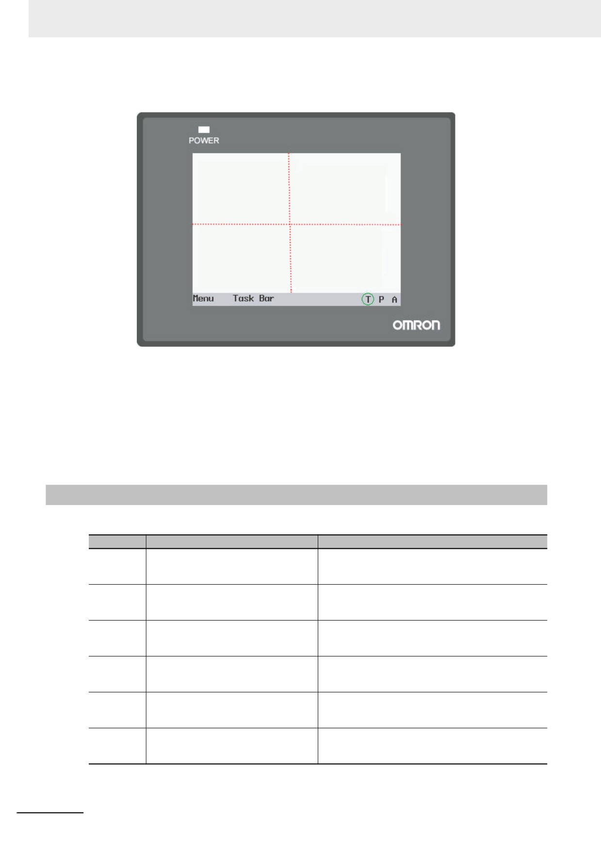
z About Keyboard Display Bits:
NB Unit divides the whole screen into 4 areas with the same size from the center, as shown below:
upper left
upper
upper right
(LB9062)
(LB9080)
(LB9066)
left
Arbitrary
right
(LB9060)
(LB9068)
(LB9065)
lower left
lower
lower right
(LB9063)
(LB9081)
(LB9067)
For each area, there is/are one or more address bit(s) corresponding to it. When the Text Input or
Number Input in the screen is triggered, the corresponding address bit(s) will be turned ON.
For example: When the Text Input or Number input in the left side of the screen is triggered, a
keyboard will pop up in the position where the specified Direct Screen locates, and at the same time,
LB9060, LB9061, LB9068 and LB9069 will be turned ON by the system. If the component is in the
upper left side, LB9062 and LB9080 will also be turned ON.
Note LB9060 and LB9061 have the same display function (i.e. to turn ON or OFF simultaneously) and it is the
same with LB9064 and LB9065, LB9068 and LB9069.
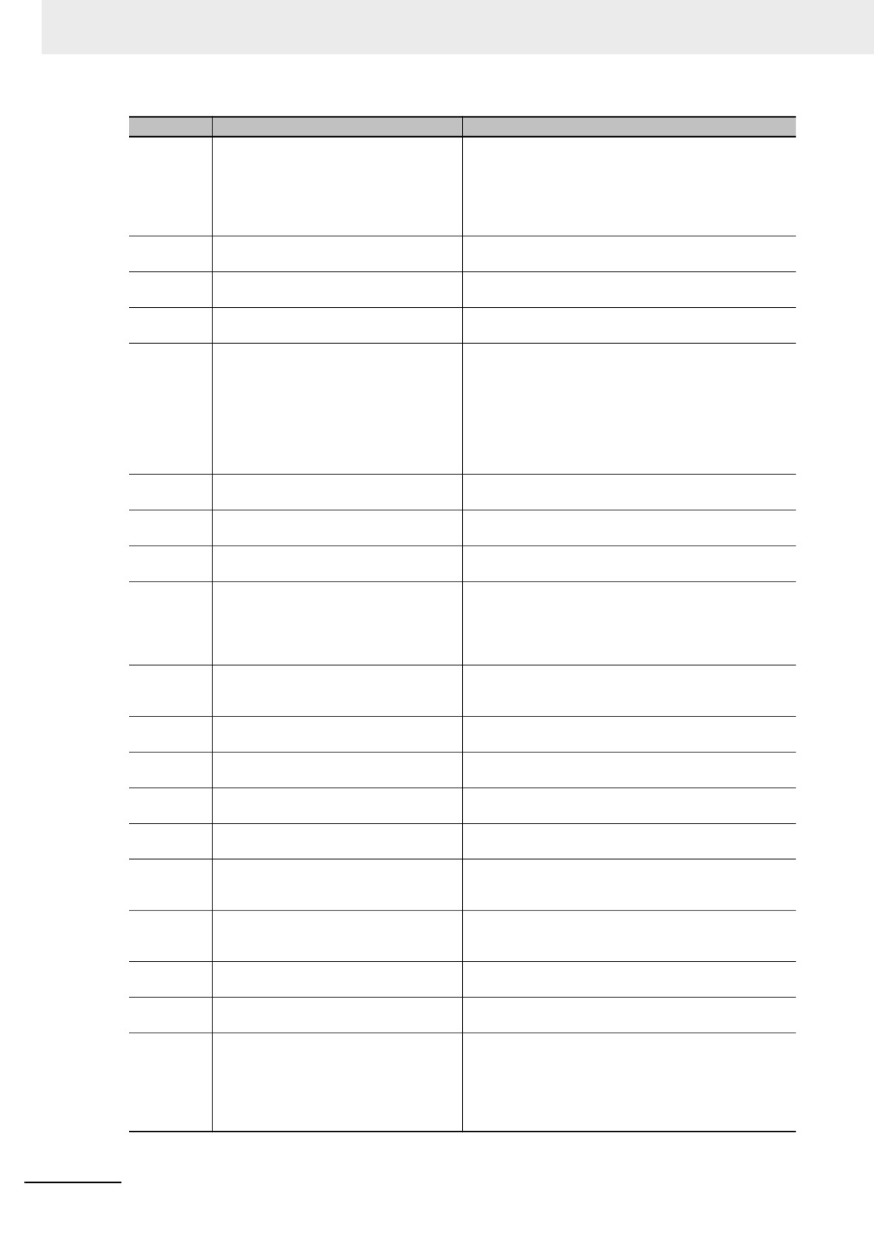
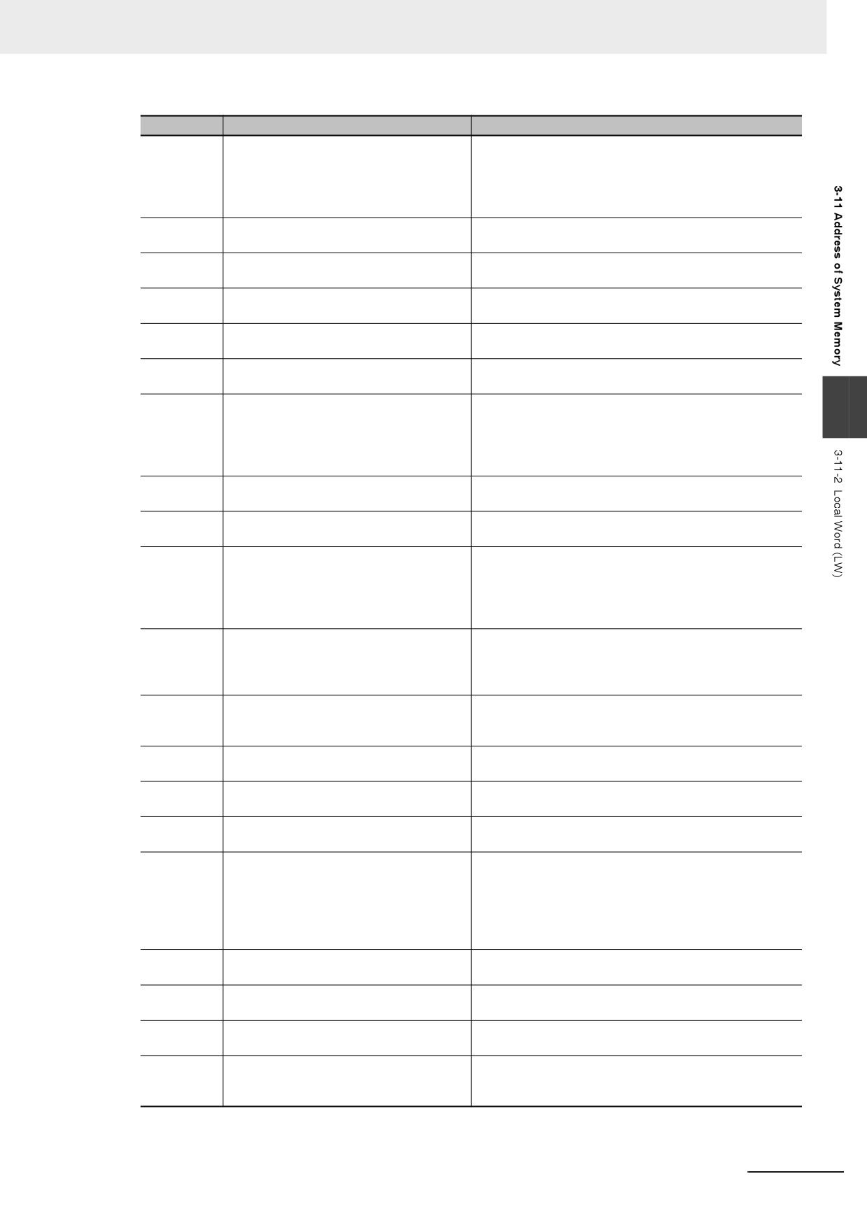
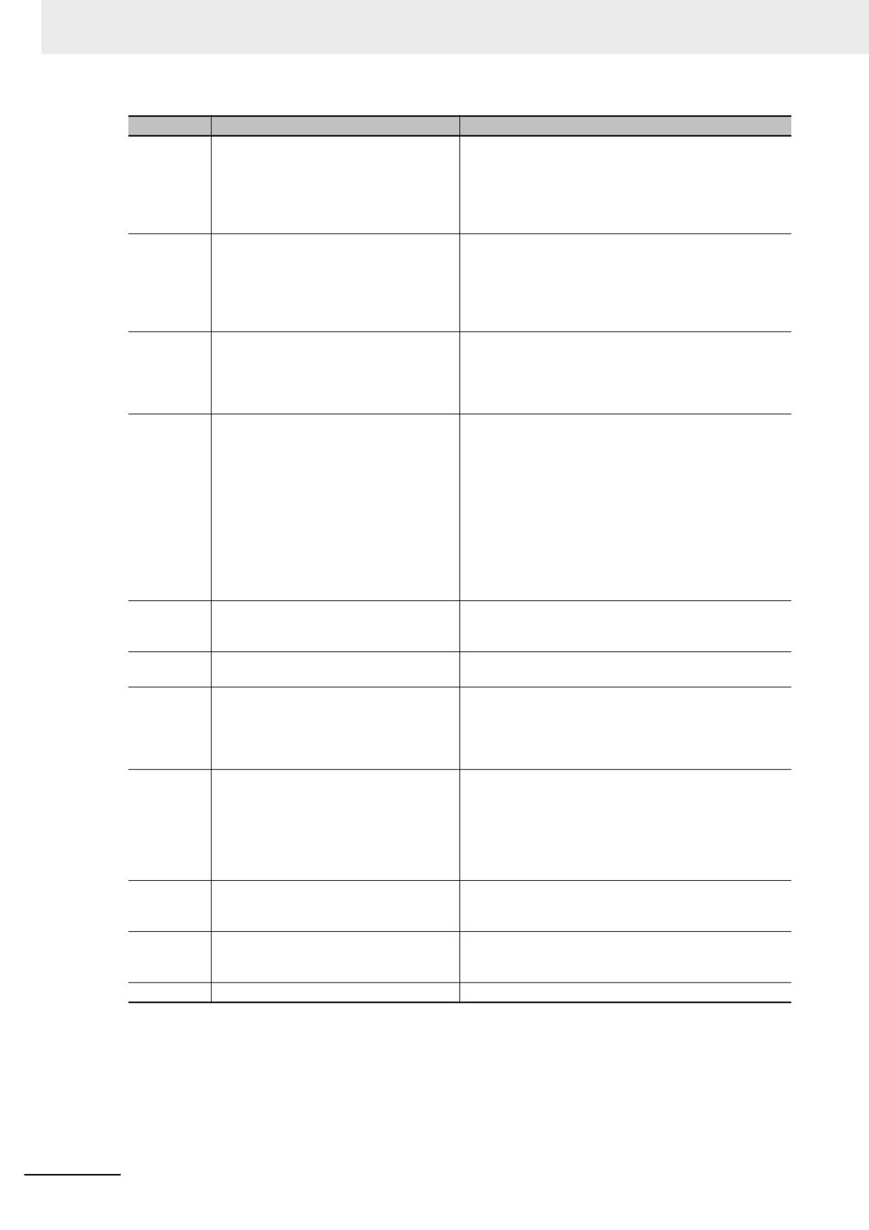
3-11-2
Local Word (LW)
Addresses
Descriptions
Comments
9000~9001
Index address of recipe data
RWI and RBI use this index address to access the
recipe data with low byte address of 9000 and high
byte address of 9001 (notification/control).
9002~9003
Maximum input number
The maximum number will be specified when the
Number Input component is activated. Otherwise the
bits will be specified to 0 (notification).
9004~9005
Minimum input number
The minimum number will be specified when the
Number Input component is activated. Otherwise the
bits will be specified to 0 (notification).
9006
Notepad operation mode
It is one function of the Notepad, which can be used to
select the operation modes from Pen (0), Eraser (1),
and Clear Block (2) (notification/control).
9007
Pen Size
It is one function of the Notepad, which can be used to
select different pen size from 1 to 8 pixels with Word
Length of 1 (notification/control).
9008
Pen Color
It is one function of the Notepad, which can be used to
select the pen color from 0 to 65535 (16-bit color)
(notification/control).
3-334
3 Functions of NB-Designer
Addresses
Descriptions
Comments
9010
Local time
Second: Effective value ranges from 0 to 59
(notification).
When the [Use External Clock] option is
9011
checked in the [PT Extended Properties]
Minute: Effective value ranges from 0 to 59
tab in the [PT Property] dialog box, the
(notification).
9012
event will not use the PT time but read
Hour: Effective value ranges from 0 to 23 (notification).
the values from LW9010 to LW9017.
9013
Day: Effective value ranges from 1 to 31 (notification).
Using this function needs to transfer the
9014
Mouth: Effective value ranges from 1 to 12
values in the time memories of PLC to
(notification).
LW9010~LW9017 accordingly in
9015
Year: Effective value ranges from 2000 to 2037
advance.
(notification).
9016
Week: Effective value ranges from 0 to 6 (notification).
9017
Millisecond: Effective value ranges from 0 to 999
(notification).
9020
Interrupt
The low byte of the LW will be sent as interrupt byte
(ranging from 0x20~0xFE) in MEMORY_LINK protocol
3
when it is not 0. The LW will be cleared to zero when
the transmission is completed successfully
(notification).
9030~9031
Touch coordinate
Records the touch coordinate taking the upper left side
of screen as origin (notification).
9034~9035
System time
Double-word. The time calculated with 0.1s as unit is
displayed (notification).
9040~9041
Security level password
Double-word. Refer to 3-13 Security Level (Page 3-
354) for details (control).
9042
Security level
Displays the security level of current Base Screen.
Refer to 3-13 Security Level (Page 3-354) for details
(notification).
9043
Switch security level forcefully
Forcefully switches from higher security level (e.g. level
2) to lower security level (e.g. level 0). Refer to 3-13
Security Level (Page 3-354) for details (control).
9050
Display Screen No.
The number of Display Screen No. is specified.
Synchronizing with the PLC by Data Transmitting
Component allows the PLC to execute the screen
transition (notification/control).
9054
Printing format1
• Bit0: Text (0:No print, 1:Print)
• Bit1: Analog meter (0:No print, 1:Print)
• Bit2: Data log (0:No print, 1:Print)
• Bit3: Bitmap (0:No print, 1:Print)
• Bit4: Vector graphics (0:No print, 1:Print)
• Bit5: Screen background (0:No print, 1:Print)
(notification/control)
9055
Printing format2
• Bit0~7:Zoom (x~0.1) (Range:1~50)
• Bit8: Color mode (0:Color, 1:Monochrome)
• Bit9: Print page (0:Current page, 1:Reserved)
• Bit10: Orientation (0:Landscape, 1:Portrait)
• Bit12: Invert color (0:Normal, 1:Inverted)
(notification/control)
9057
Size of each item of the event history
The recipe memory is used to save the size of each
item by the event log data (notification).
9058~9059
Size of event log data
The recipe memory is used to store the size of event
history including management information
(notification).
3-335
3 Functions of NB-Designer
Addresses
Descriptions
Comments
9060~9075
Display of number input or text input
Displays the data input by Number Input or Text Input
process
component in real time, and clears it after completion of
input. If input component is set to 1 word, only LW9075
is used; while LW9074 and LW9075 are both used if
input component is set to 2 words, and so on
(notification).
9091
Project compilation [year]
Records the project compilation time [year]
(notification).
9092
Project compilation [month]
Records the project compilation time [month]
(notification).
9093
Project compilation [day]
Records the project compilation time [day]
(notification).
9100
Modify dynamically the address in the
9100 is the Screen No. The 9101 is the offset
screen (internal address)
(notification/control).
9101
When LW9100 is set to 11 and LW9101 is set to 20,
the PLC addresses of all the component in the screen
11 will be modified dynamically to the addresses in
which the offset are added. i.e. D10 will become D30
and the offset of 20×16=320 will be added to all bit
addresses, i.e. M20 will become M340.
9130
Dynamic modification of Text Library
The value of this LW represents the index of Text
Library (notification/control).
9136~9137
Currently available memory space [byte]
Double-word. The currently available memory space is
stored. Do not write values (notification).
9138~9139
The total memory [byte]
Double-word. The total memory is stored. Do not write
values (notification).
9140
Display brightness level
Displays the brightness level for NB Unit with the range
from 0 (completely dark) to 32 (completely bright).
The setting is linked with Brightness of the System
Menu of NB Unit. The value is retained when power is
OFF (notification/control).
9150
Character code displayed in the current
The value of LW9150 is the No. of Chinese characters
screen when using Pinyin
displayed in the current Chinese character display
screen (notification).
9152~9167
Characters displayed by Chinese pinyin
Display Pinyin character input currently when using
input
Pinyin (notification).
9170
Page up/down of Note Book component
The value of this LW means the start line of input area
(notification).
9180~9187
Maximum value of Number Input
Text display of maximum value of Number Input
(notification).
9190~9197
Minimum value of Number Input
Text display of minimum value of Number Input
(notification).
9200~9205
Time value of browsing point of Data Log
These six words are used to display second, minute,
hour, day, month and year respectively in BIN code
(notification).
9210
Display values of each channel during
The current value of each channel is displayed one by one
referencing
according to the bit width of the browsed Data Log
(notification).
9260~9261
Start address for RW clearing operation
Sets the start address for RW clearing operation
triggered by LB9130 (notification/control).
9262~9263
Word length of RW clearing operation
Sets the word length for RW clearing operation
triggered by LB9130 (notification/control).
9264~9279
Mask code of PLC Station No.(COM 2)
Each bit corresponds to one Station No. of COM 2 (i.e.
9264.0 corresponds to Station No. 0... and 9279.F
corresponds to Station No. 255). When the bit is turned
ON, the communication corresponding to Station No.
will be stopped. The value is retained when power is
OFF (notification/control).
3-336
3 Functions of NB-Designer
Addresses
Descriptions
Comments
9296~9299
Mask code of error information
Each bit corresponds to one piece of error information.
When the bit is turned ON, the corresponding prompt
error information will not be displayed. Refer to 3-11-4
System Information Table (Page 3-341) in NBDesigner
Operation Manual for details (notification/control).
9300
Name of path referred by File List
The name of path currently referred (32 words) by the
component
File List Component will be specified (notification).
9332
Name of file selected by File List
The name of file selected (32 words) by the File List
component
Component will be specified (notification/control).
9364
Setting Import and Export
Specify the Import and Export of the project and the
Recipe (notification/control).
9366
Description of processing File Browsing
“1” indicates Copy, “2” does Cut, and “3” does Paste,
Component
respectively (control).
9370
Confirm Operation method
Confirm Operation method: 1: Confirm; 2: Cancel
(control).
9371
General-purpose PLC control time-out
Automatically stops a general-purpose PLC control if
3
the general-purpose PLC control has not been
performed before elapsing the time (second) that you
set here. The default is 0 (not to stop the control)
(notification/control).
9380~9395
History value of Number Input component
Specify the data set before the input operation
(notification).
9416~9431
Index memory for Station No. variable
Each word corresponds to the index (0~15) for Station
No. variable (notification/control).
9432~9447
memory for indicating communication
Each bit corresponds to one Station No. (9432.0
state (COM 2)
corresponds to 0,..., and 9447.F corresponds to 255).
The relevant bit is set to ON when PLC is under time-
out condition and has no response, otherwise it will be
set to OFF (notification).
9465
Time-out ratio of Macro
Specify the maximum time allocating to the execution of a
Macro. The time multiplying the default value, 200 ms with
the specified value will be the maximum time
(notification/control).
9470~9485
File name of the screen shot
The prefix text string of 16 words naming the screen
shot which is stored in USB memory
(notification/control).
9486~9501
User name
Inputs the login user name of up to 32 characters
(notification/control).
9502~9503
User password
Inputs the password corresponding to the login user
(notification/control).
9504~9505
Current user permission
Displays 32 authorities corresponding to current login
users (notification).
9506~9507
Authority setting
Double-words and 32 authorities’ assignments.
LW9506 to LW9507 corresponds to 32 authorities (No.
0 to No. 31) and LW.B corresponds to each bit in
LW9506 to LW9507. For example: LW.B 9506.0
represents the authority of No. 0; and LW.B 9506.A
represents the authority of No. 10 (control).
9508~9509
Automatic Logout Time setting
Sets the unit of automatic logout time to minute during
the addition of user information (control).
9510~9511
Password Confirm
Inputs the password again for consistency confirmation
during the addition of user information (control).
9520~9521
Curser position
Refers to the curser position (X,Y) in input component
(notification).
9535
The multiplication factor of the
If it is specified to “N”, the maximum communication
communication time for the Macro
time of the Macro external value is N times as long as
instruction
the default (notification/control).
3-337
3 Functions of NB-Designer
Addresses
Descriptions
Comments
9536
The multiplication factor of the
Sets a time-out period of writing by data transmission
communication time for writing operation
component. The setting value is the coefficient for the
by the data transmission component
maximum size of a block package that is set in the
communication settings.
Refer to 5-3 Abnormality Handling (page 5-6) for details
(notification/control).
9537
The multiplication factor of the
Sets a time-out period of reading by data transmission
communication time for reading
component. The setting value is the coefficient for the
operation by the data transmission
maximum size of a block package that is set in the
component
communication settings.
Refer to 5-3 Abnormality Handling (page 5-6) for details
(notification/control).
9551~9554
Notifying error information
Each bit corresponds to each error information. When
the bit turns ON, the bit indicates that the corresponded
error information occurs. Refer to 3-11-4 System
Information Table (Page 3-341) in NBDesigner
Operation Manual for details (notification).
9605~9606
Communication Control
Communication via a port is stopped when a bit for
each port is ON. The value is retained when power is
OFF (notification/control).
Note: OFF (communication allowed) is default.
9605.0: COM2 port
9605.1: Reserved
9605.2: COM1 port
9605.3-9606.A: An Ethernet host is allocated in
ascending order of the station number (24 hosts).
9606.B and later: Reserved
9607~9608
Number of flash memory rewrites
Indicates the number of times the block on the flash
memory has been rewritten most frequently
(notification).
9609~9610
Number of bad blocks on flash memory
Indicates the number of bad blocks on the flash
memory (notification).
9685
Communication setting change for a
Set a PLC number to designate a host whose Ethernet
host
communication setting is to be changed. PLC number
is set from 3 in ascending order, not from the PLC
number itself. Used in combination with LB9272
(control).
9686~9689
IP address for communication setting-
Set a host's IP address whose communication setting
changed host
is to be changed. Used in combination with LB9272
(notification/control).
[Sample]
IP address: 192.168.250.1
LW9686:192, LW9687:168, LW9688:250, LW9689:1
9690
Port number for communication setting-
Set a host's port number whose communication setting
changed host
is to be changed. Used in combination with LB9272
(notification/control).
9691
Node number for communication setting-
Designate a host's FINS node address whose
changed host
communication setting is to be changed (notification
/control). Enter the same value as the least IP address.
9800~9801
Error code of the triggering error
(notification/control)
3-338
3 Functions of NB-Designer
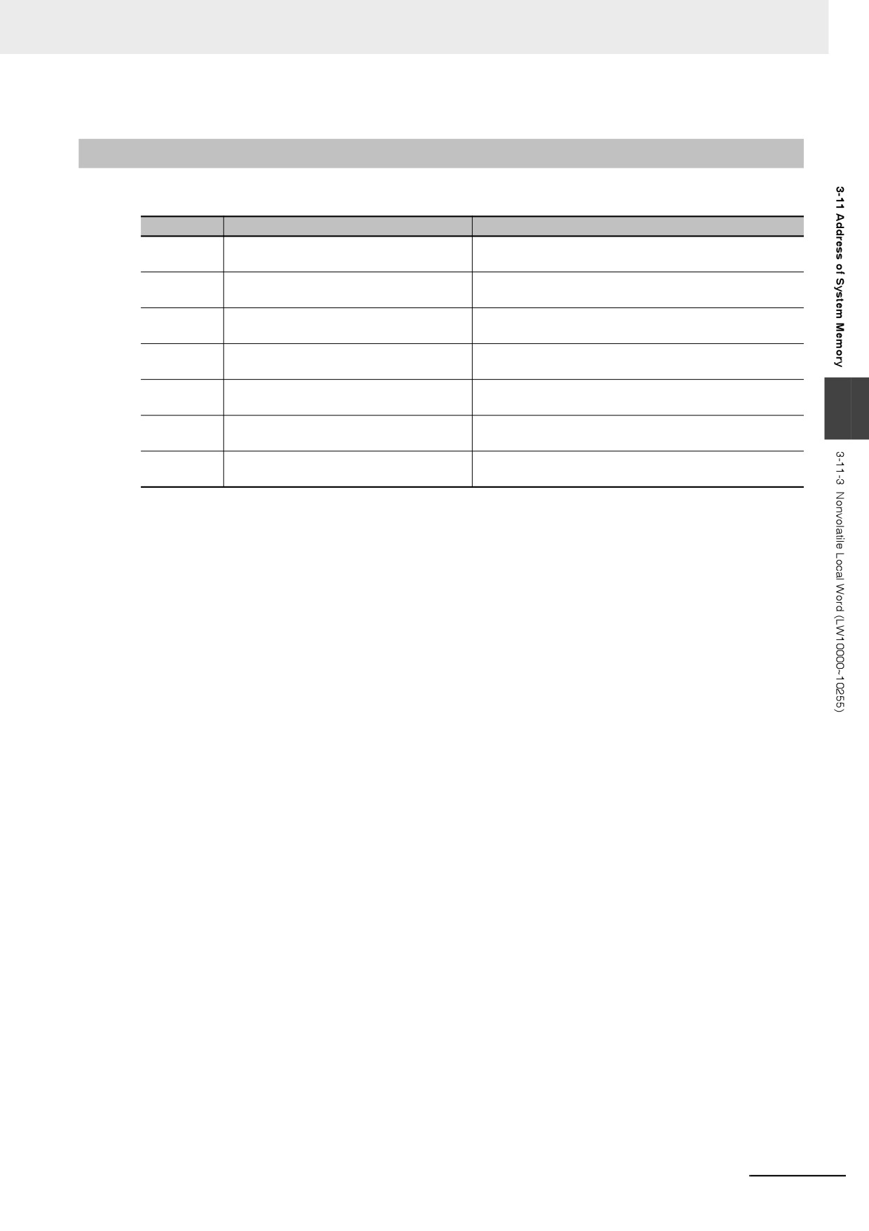
3-11-3
Nonvolatile Local Word (LW10000~10255)
RTC
Addresses
Descriptions
Comments
10000
RTC (second)
BIN code with effective value ranging from 0 to 59
(notification/control)
10001
RTC (minute)
BIN code with effective value ranging from 0 to 59
(notification/control)
10002
RTC (hour)
BIN code with effective value ranging from 0 to 23
(notification/control)
10003
RTC (day)
BIN code with effective value ranging from 0 to 31
(notification/control)
10004
RTC (month)
BIN code with effective value ranging from 1 to 12
(notification/control)
3
10005
RTC (year)
BIN code with effective value ranging from 1971 to
2037 (notification/control)
10006
RTC (week)
BIN code with effective value ranging from 0 to 6
(notification/control)
Description of RTC:
Users can use the related “Component” to display the time. Pay attention to the effective range. The operation
when the values out of the effective range is not ensured.
For example: “second” can not be written as 78 (BIN), otherwise RTC will continue in sequence (78 79 80 ...),
which may result in unexpected error.
3-339
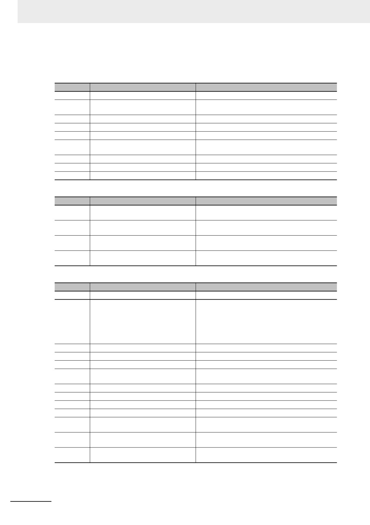
3 Functions of NB-Designer
Others:
The following notification or control addresses are retained even if power failure occurs. The addresses
other than Backlight saver, Buzzer, Password will be valid after the restart.
System parameter settings
Addresses
Descriptions
Comments
10010
No. of Initial Screen
It ranges from 0 to 32767.
10011
Backlight saver
0 (Disable Backlight saver)
1 to 600 minutes (enabled)
10012
Buzzer
0: Disabled, 1: Enabled
10013
Common Sheet/Pop-up Screen
0: Normal, 1: At the top of all the other screens
10014
Placing Common Sheet
0: At the bottom of Base Screen, 1: At the top of Base Screen
10015
Number of stored events
It ranges from 0 to 65535. If it is set to “0”, the event
data will be cleared after the restart.
10016
Source of RTC
0: Internal RTC, 1: PLC (LW)
10017
Default language
It ranges from 0 to 31.
10018
Reserved by system
Security level
Addresses
Descriptions
Comments
10022~
Password/0
Reserved.
10023
10024~
Password/1
Double-word is occupied.
10025
10026~
Password/2
Double-word is occupied.
10027
10118~
Password/3 to 15
Double-word is occupied × 13.
10143
Initial Communications Parameters
Addresses
Descriptions
Comments
9039
FINS node address of the NB Units
If it is changed, restart is needed
10030~
IP Address of the NB Units
If it is changed, restart is needed
10033
i.e. IP Address: 192.168.250.1
LW10030:1,
LW10031:250,
LW10032:168,
LW10033:192
10034
Port Number of the NB Unit
If it is changed, restart is needed
10035
Reserved by system
10036
COM 2 operation mode
0: RS-232, 1: RS-422, 2: RS-485.
10037~
COM 2 Baud Rate
Double-word.
10038
10039
COM 2 Data Bit
10040
COM 2 Parity Bit
10041
COM 2 Stop Bit
10042
COM 2 Station No. (PT Station No.)
10043~
COM 2 PLC timeout duration
10044
10045~
COM 2 Protocol Time Out 1
10046
10047~
COM 2 Protocol Time Out 2
10048
Note The addresses 9,039 and greater than 10,000 cannot be modified during simulation. But the read operation
is available (For example, the Number Input component with the address of LW10005 will be displayed as
2006 during the test, and it can’t be modified to the other value during the test. But it can be modified only
after it is downloaded to the PT. ).
3-340
3 Functions of NB-Designer
3-11-4
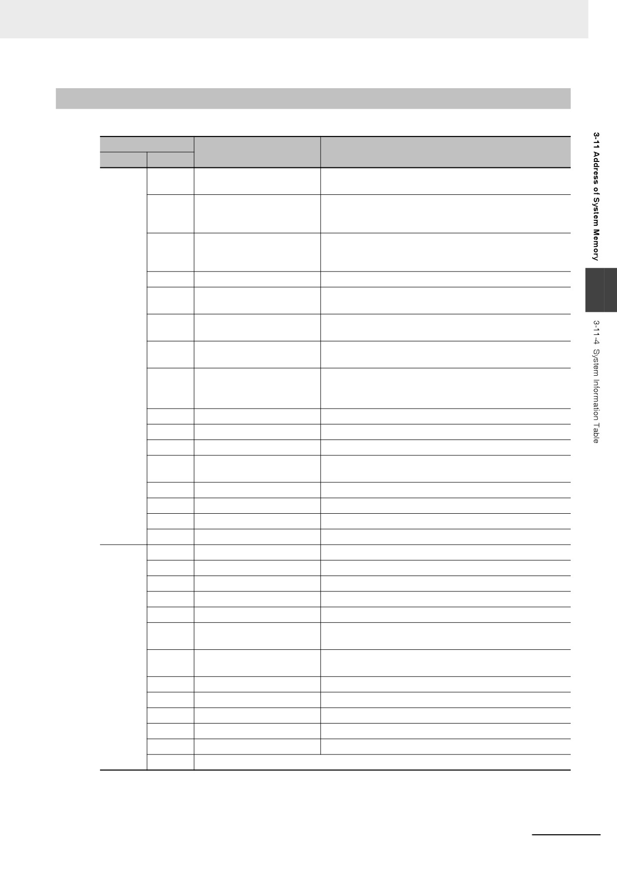
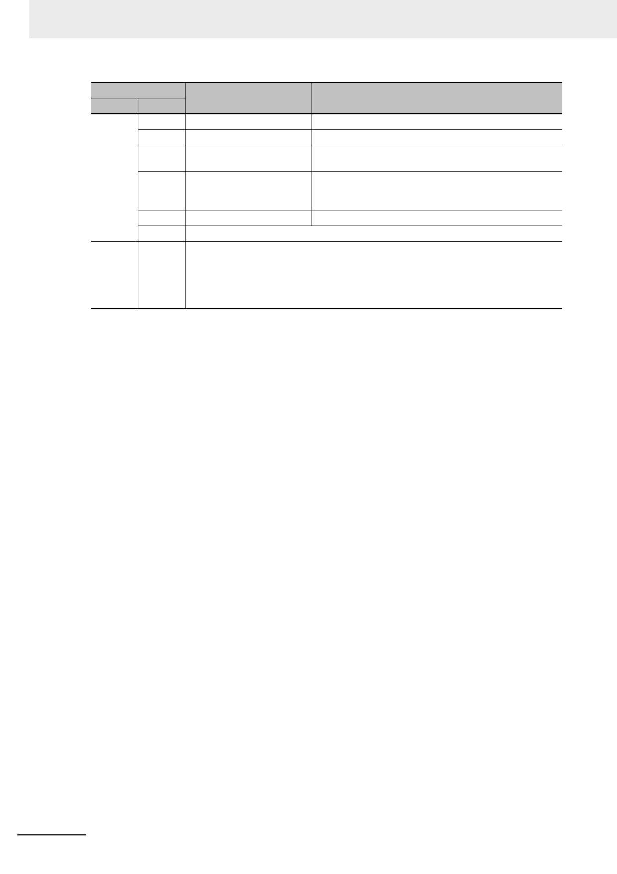
System Information Table
Address
Information
Descriptions
Word
Bit
Mask
0
System Error
It is system error which means the error occurs inside the
9296
PT.
1
PLC Response Error
PLC response error: PLC responds with one piece of
Notify
unexpected information which may caused by the read or
9550
write command. Please check if the device functions well.
2
PLC No Response: cc-pp-d
PLC No Response: the 3 groups of numbers following PLC
No Response represent the PT No., PLC Station No. and
Serial Port No. respectively.
3
Reserved by system
3
4
Socket Connect Error
Connection with the PLC and others failed. Check if the
devices function normally.
5
Socket COMM Error
An error occurred during the connection with the PLC and
others. Check if the devices function normally.
6
Macro Code Error: [xxxx]
An error occurred during executing a Macro. The
(Macro No.)
description enclosed by the parenthesis is the Macro No.
7
Print Error
Printing error: It is followed by the error code. Refer to 7-5
List of Error Codes for Printing (Page 7-9) in NB-
Designer Operation Manual for details.
8
Send Package Error
Message transmission fails.
9
Memory Shortage
Memory is not enough.
10
BCD Transform Overflow
BCD conversion overflows.
11
MacroCode Timeout: [xxxx]
A timeout occurred during executing a Macro. The
(Macro No.)
description enclosed by the parenthesis is the Macro No.
12
Reserved by system
13
Reserved by system
14
RW Area Access Overflow
RW area access exceeds the limits.
15
Waiting to Print
It indicates waiting for print.
Mask
0
Server Not Ready
The data in server is not ready.
9297
1
Reserved by system
2
Transmit Data Failed
The data transmission failed.
Notify
3
Data Input Failed
The number input failed.
9551
4
Device Error
Failure occurs in the device.
5
Copying File ...
The file is being copied (This is the normal prompt during
the project export or screenshot operation).
6
Copy File Failed
The file copy failed (during exporting the project or
performing screen shot).
7
Invalid File
The files objected of importing are invalid.
8
Password Error
The password is invalid.
9
Reserved by system
10
USB Disk1 Full
USB memory 1 is full already.
11
Reserved by system
12-15
Reserved by system
3-341
3 Functions of NB-Designer
Address
Information
Descriptions
Word
Bit
Mask
0
RTC Device Error
An error occurred in RTC clock.
9298
1
Reserved by system
2
Invalid UserName
The user name is invalid (The input user name is invalid
Notify
during the user login or user addition/deletion operations.)
9552
3
Operation Complete
It indicates the operation is successful (This is the correct
prompt displayed after user addition/deletion or password
modification.)
4
Print Busy
It indicates printing.
5-15
Reserved by system
Mask
0-15
Reserved by system
9299
Notify
9553
3-342
3 Functions of NB-Designer
3-12 Recipe Data
The component of the Recipe transmits the data with consecutive memories. And the data can be
downloaded from the recipe memory to the PLC or uploaded from the PLC to the recipe memory. The
size of the data to be transferred can be set. For the NB Unit, the recipe memory with 128K word can
be selected for recipe data storage.
3-12-1
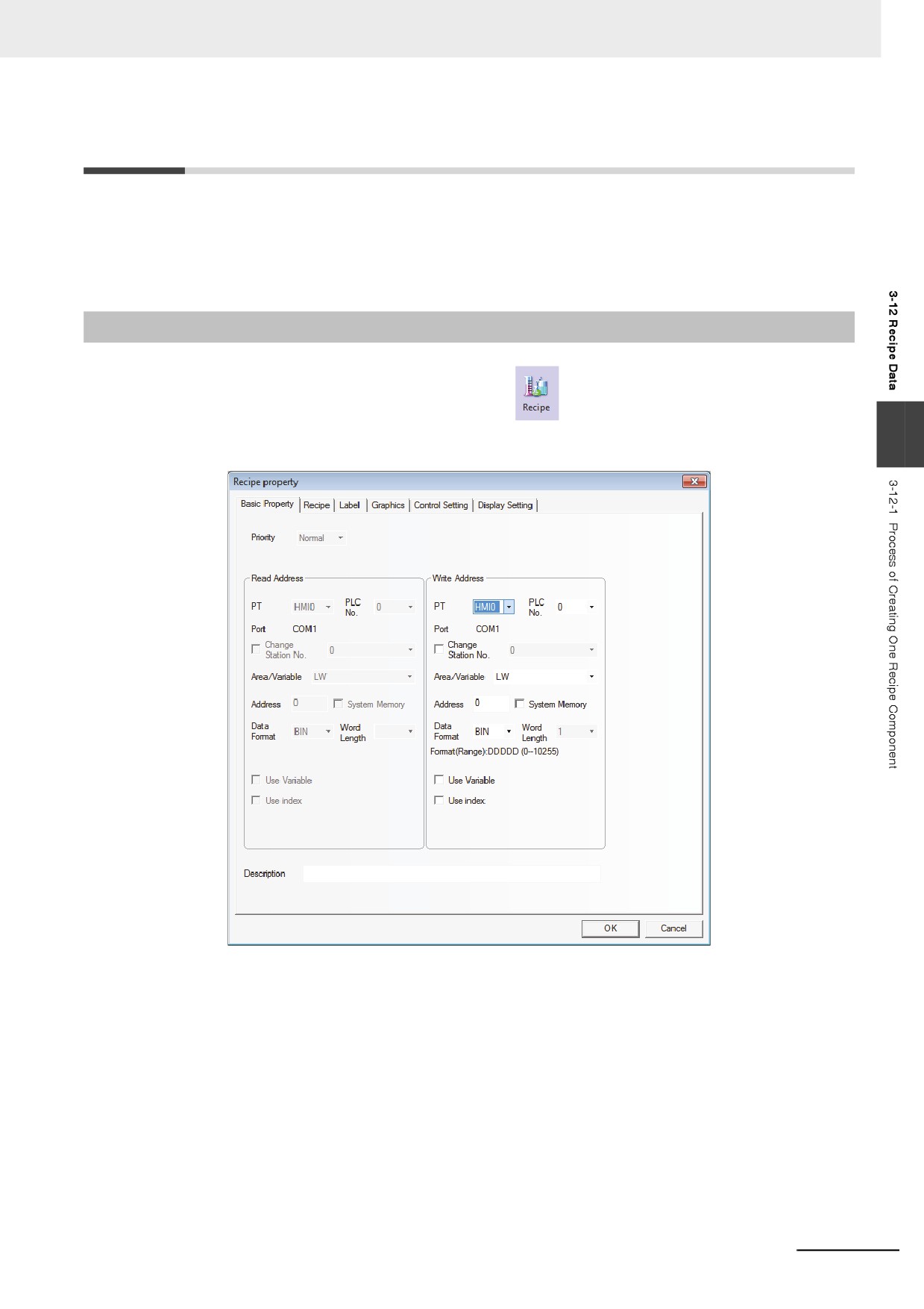
Process of Creating One Recipe Component
1
Drag the icon of Recipe to the Edit Window,
and then fill the contents in [Basic
Properties] tab:
3
Write Address: Specify the starting address of the PLC which transmits the Recipe data. The
address for [Data Length] specified in the [Recipe] tab of the [Recipe Property]
dialog box are used for the data transmission with the Read Address on the
top.
Address: Specify the starting address at the PLC to transmit the Recipe data.
Word Length: The function does not support the parameter.
3-343
3 Functions of NB-Designer
2
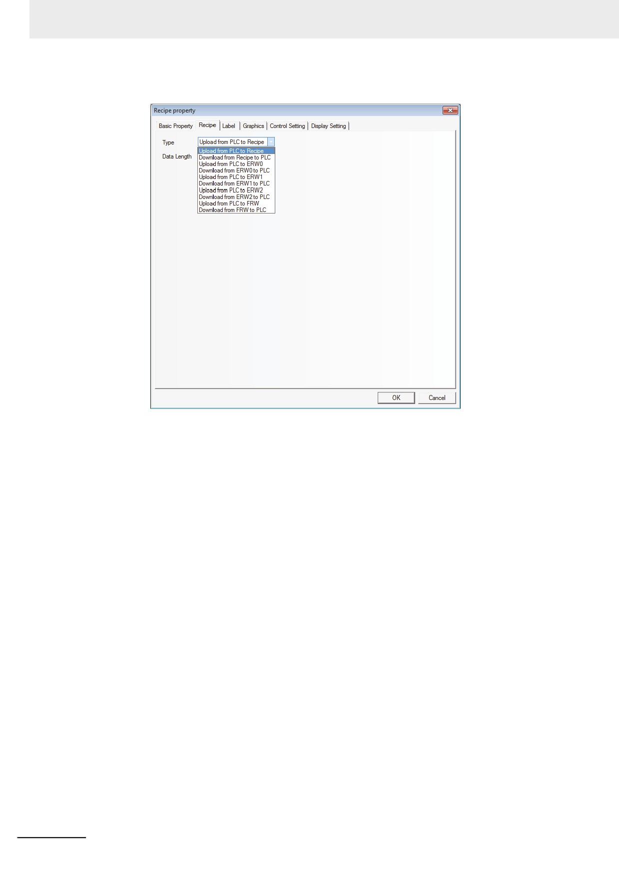
Switch to the [Recipe] tab and set the Function and Data Length.
Function:
Upload from PLC to Recipe: Transfers the data from PLC to the recipe memory of PT.
Download from Recipe to PLC: Transfers the data from the recipe memory of PT to PLC.
Transmit from PLC to FRW: Transmit the data from PLC to the Recipe memory ERW.
Transmit from ERW to PLC: Transmit the data from the Recipe memory ERW of PT to PLC.
Upload from PLC to FRW: Transfers the data from PLC to the recipe memory FRW of PT.
Download from FRW to PLC: Transfers the data from the recipe memory FRW of PT to PLC.
Data Length: Refers to the word length of the data to be transferred.
3
Switch to the [Label] tab and add the different displayed texts corresponding to the different
states.
4
Switch to the [Graphics] tab and select the Vector Graphics or Bitmap to display the graphics
corresponding to the state of the Recipe Data component.
5
Switch to the [Control Setting] tab and make the Security Setting and set the Triggering action.
6
Press the [OK] button, and adjust the position and size of the component.
3-344
3 Functions of NB-Designer
3-12-2
Recipe Memory
The recipe memory stores in a flash memory, and even if power interruption occurs, the data can be
retained.
The recipe memory space of NB3Q/NB5Q-TW B model is 128K (Word), and for that of
NB7W/NB10W-TW B model, it is 256K (Word).
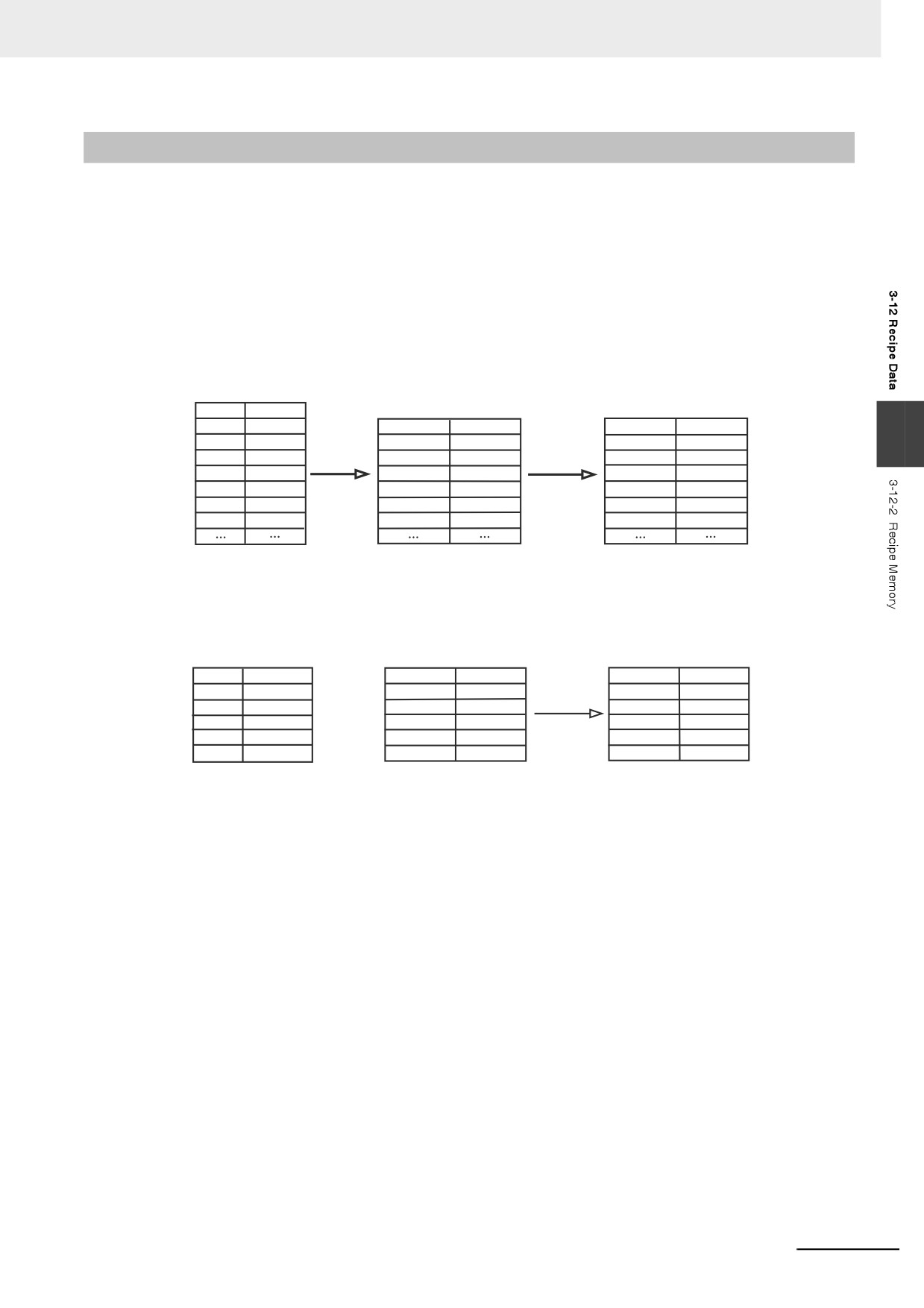
There are 2 indication methods for the recipe memory, i.e. “RW” represents the absolute address while
“RWI” represents the index address. The data in “LW9000” is the offset of the index address. For
example, when the data in LW9000 is 50, the index address RWI0 will point to the data in address
RW50. In this case, if we change the data in LW9000 to 51, then the index address RWI0 will point to
the data in address RW51, as shown below:
LW9000=50
LW9000=51
Address
Data
RW50
0x1111
Address
Data
Address
Data
3
RW51
0x2222
RWI0
0x1111
RWI0
0x2222
RW52
0x3333
RWI1
0x2222
RWI1
0x3333
RW53
0x4444
RWI2
0x3333
RWI2
0x4444
RW54
0x5555
RWI3
0x4444
RWI3
0x5555
RW55
0x6666
RWI4
0x5555
RWI4
0x6666
RW56
0x7777
RWI5
0x6666
RWI5
0x7777
For example, we specify one project and select [MODBUS RTU] as the PLC Type in system
parameters. The function of transferring the 5-word text beginning from address 200 with the address
type of 4X to the address of recipe memory (RW300) is as shown below:
Before uploading
After uploading
Address
Data
Address
Data
Address
Data
4X200
'A','B'
RW300
'B','B'
RW300
'A','B'
4X201
'C','D'
RW301
'C','C'
RW301
'C','D'
4X202
'E','F'
RW302
'D','D'
RW302
'E','F'
4X203
'G','H'
RW303
'E','E'
RW303
'G','H'
4X204
'I','J'
RW304
'F','F'
RW304
'I','J'
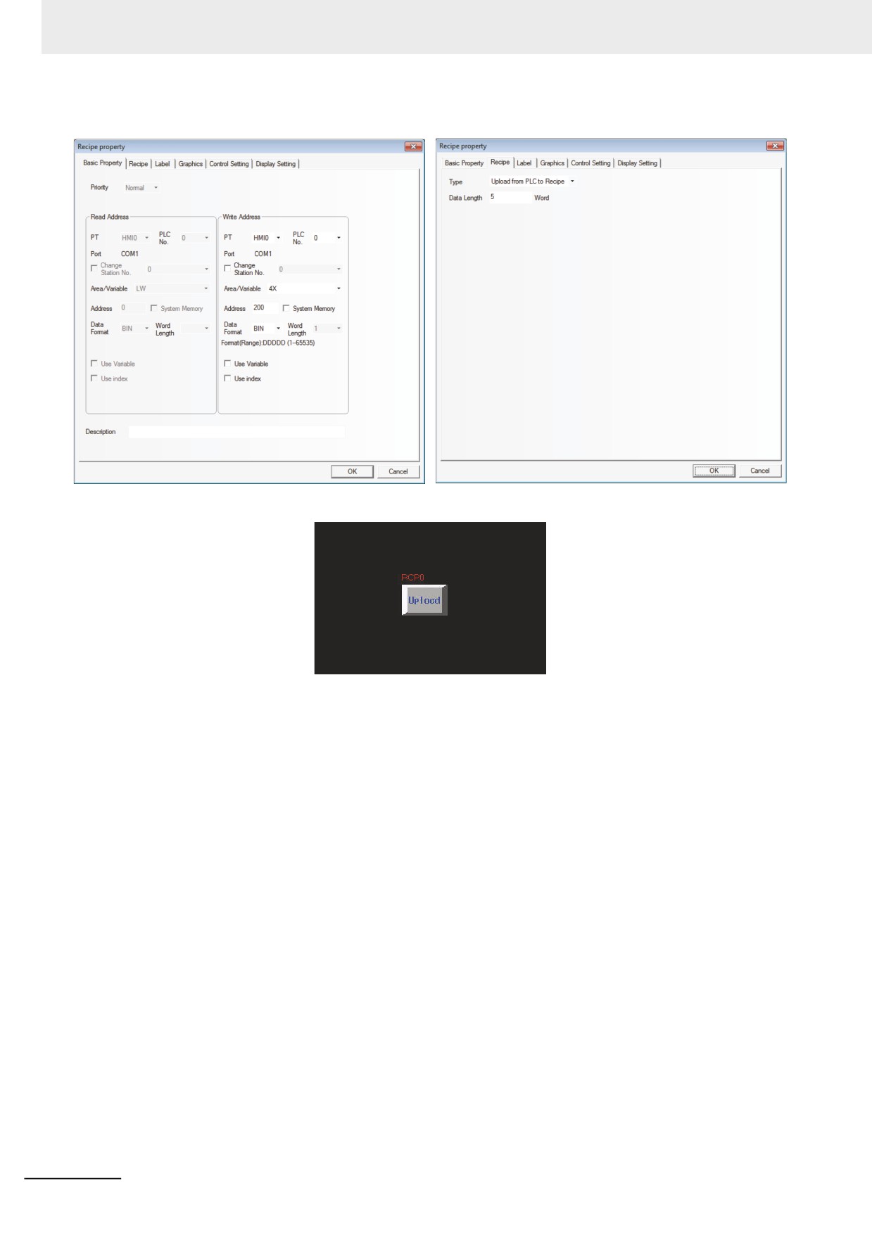
Create a new project and select [MODBUS RTU] as the PLC type in [Project Library Window].
Firstly, create a component to upload the recipe data with the Area/Variable of 4X, Address of 200,
Function of Upload, Word Length of 5, and [Transport Font] being checked, and the Label of “Upload”,
as shown below:
3-345
3 Functions of NB-Designer
Then place the component in the screen.
Now the recipe data transmission component is created, but it can only specify to transfer the 5 words
beginning from address of 4X200 to the recipe memory instead of the specific position of the recipe
memory. Set the LW9000 to 300 and press “Upload” button, then the 5 words beginning from 4X200
will be transferred to the 5-word addresses after the start address of RW300. If you want to transfer the
5 words beginning from the address of 4X200 to RW100 again, then you just need to set LW9000 to
100, and then press “Upload” button to complete the data transmission.
Place 3 Text Input components to modify/display the data.
(1)
4X200: Area/Variable of 4X, Address of 200 and Word Length of 5.
(2) RWI0: Area/Variable of RWI, Address of 0 and Word Length of 5.
(3) RW300: Area/Variable of RW, Address of 300 and Word Length of 5.
Then create one Number Input component to modify the data of LW9000. Specify LW for
[Area/Variable] and 9000 for [Address].
3-346
3 Functions of NB-Designer
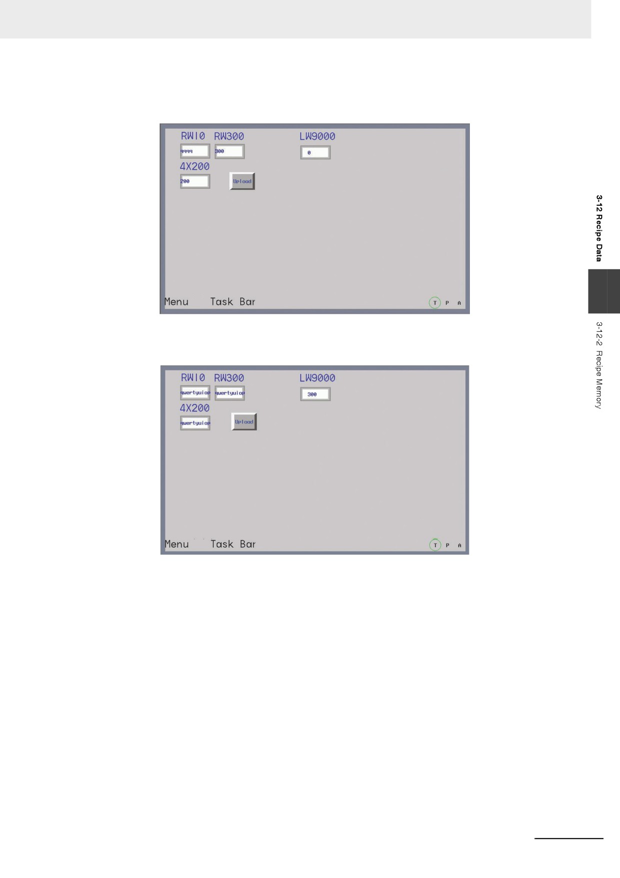
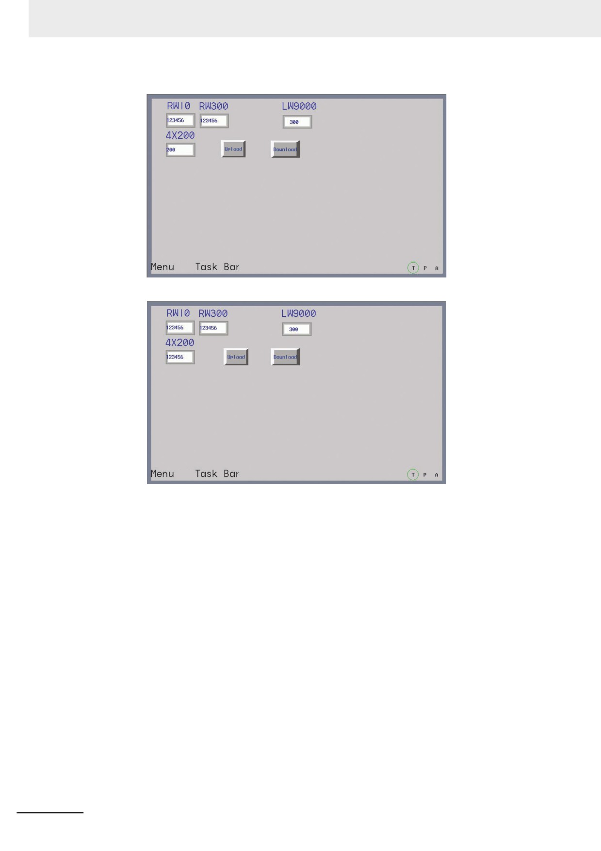
After Save, Compile operations, perform the offline test for the project. Firstly, change LW9000 to 300
(because LW9000 represents the offset of the index address, RWI0 will display the data in the address
of RW300), as shown below:
3
Input “QWERTYUIOP” to 4X200, and 300 to LW9000, then you will find the data displayed by RWI0,
RW300 and 4X200 is the same after the Upload button is pressed, as shown below, which means the
upload is successful.
How to download the 5 words with the start address of RW300 to the position with the start address of
4X200? The specific operation process is described as follows. Add one recipe data transmission
component in the project just mentioned above with the Area/Variable of 4X, Address of 200, Function
of Download from Recipe to PLC, Word Length of 5 and Label of “Download”.
3-347
3 Functions of NB-Designer
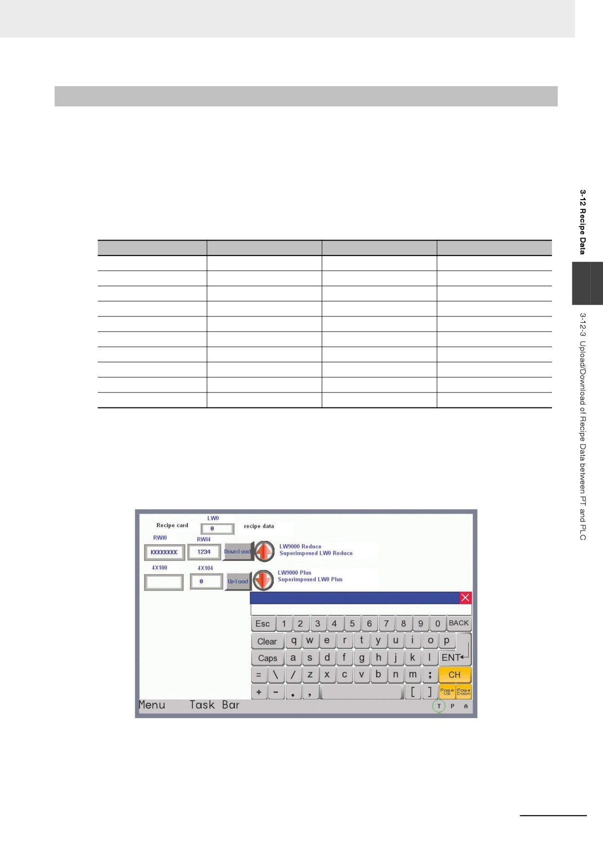
Perform the offline test, change LW9000 to 300 and input “123456” to RWI0, as shown below:
Press the Download button, then you will find the text data will be transferred to 4X200 from RW300.
Whether we upload the data from PLC to recipe or download the data from recipe to PLC, the start
address of data in recipe is always the value corresponding to LW9000.
3-348
3 Functions of NB-Designer
3-12-3
Upload/Download of Recipe Data between PT and PLC
The recipe data is significantly useful. For example, the production device can operate differently
according to the different parameters assigned to them on the industrial production line. Now, we can
save this group of data in the specific format in the recipe memory, then we can call them out directly,
thus enhancing productivity.
z Example of how to call several recipe data conveniently
It is assumed that we have 10 groups of recipes; each group is made of 5 words, recipe name
occupying 4 words and recipe data occupying 1 word. Then we configure the recipe from RW0, as
shown below:
Recipe No.
memory Address
Recipe Name (4 words)
Recipe Data (1 word)
Group 0
RW0-RW4
“AAAAAAAA”
0
Group 1
RW5-RW9
“BBBBBBBB”
1111
3
Group 2
RW10-RW14
“CCCCCCCC”
2222
Group 3
RW15-RW19
“DDDDDDDD”
3333
Group 4
RW20-RW24
“EEEEEEEE”
4444
Group 5
RW25-RW29
“FFFFFFFF”
5555
Group 6
RW30-RW34
“GGGGGGGG”
6666
Group 7
RW35-RW39
“HHHHHHHH”
7777
Group 8
RW40-RW44
“IIIIIIII”
8888
Group 9
RW45-RW49
“JJJJJJJJ”
9999
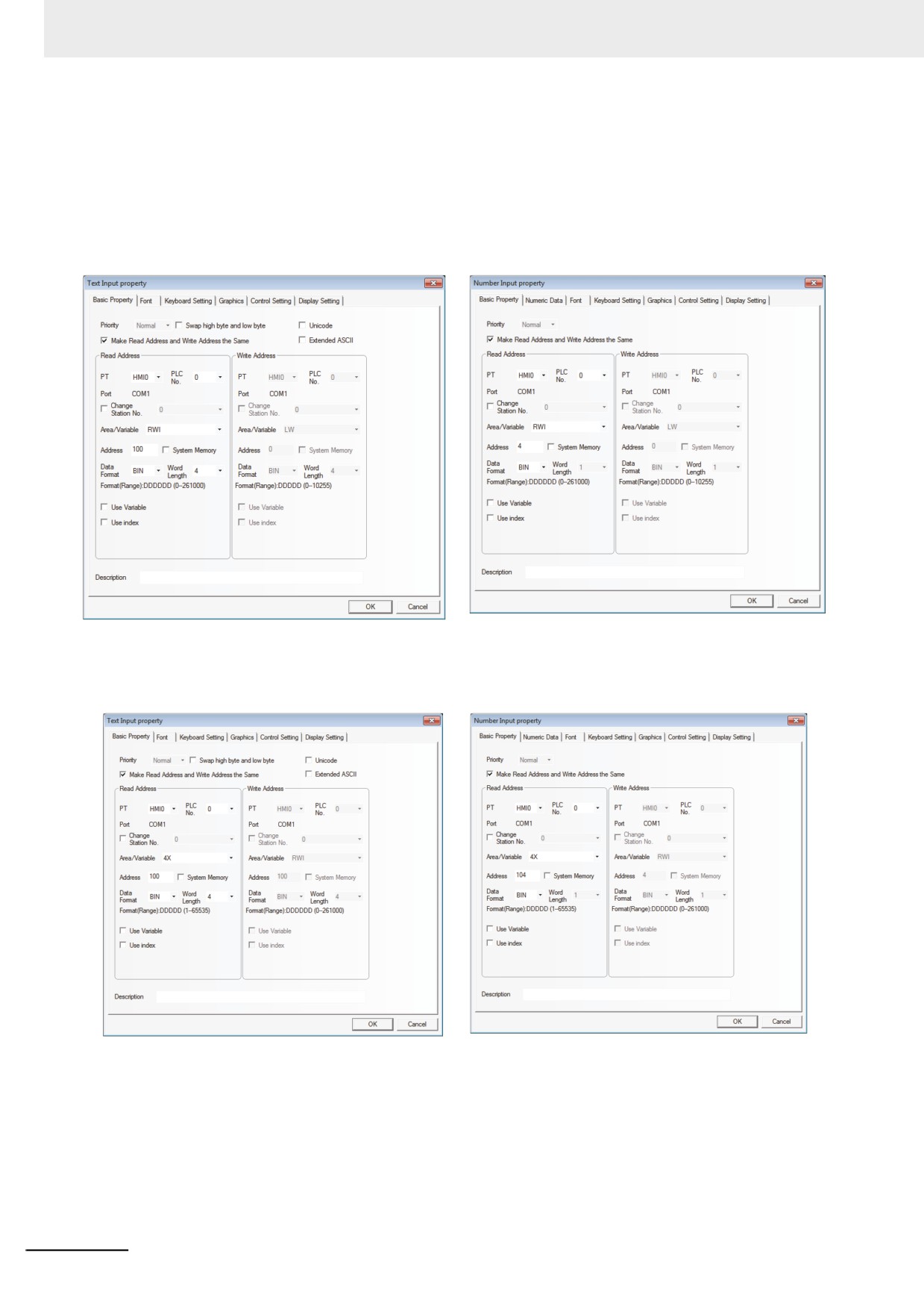
We hope each group of recipe in the above table can perform data swap with 4X100 memory of our
PLC conveniently through design. First, let’s see the following created project to obtain the general
understanding. RWI0 and RWI4 in the project display the data in Group 0, and pressing the Download
button can download the recipe data to 4X100 while pressing the Upload button can upload the data in
4X100 to the recipe memory. The Up button on the right is used to modify the Recipe No. to a level
smaller, which is convenient to change or transfer the recipe data; and the Down button on the right
side is used to modify the Recipe No. to a level larger.
3-349
3 Functions of NB-Designer
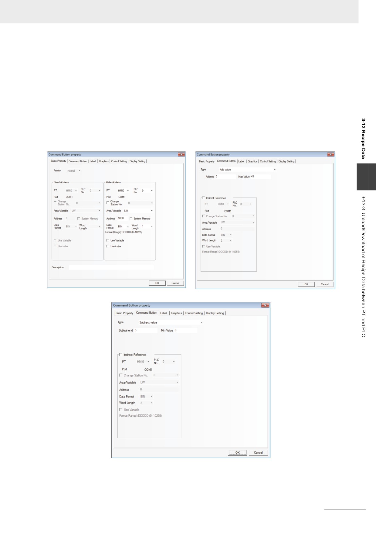
Firstly create a new project, and select the [MODBUS RTU] as the PLC in [Project Library Window].
1
Create one Text Input component with Word Length of 4 to display and change the name of
each group of recipes.
2
Create one Number Input component to display and change each group of recipe data.
3
Create one Text Input component and one Number Input component to display and change the
recipe data in PLC.
3-350
3 Functions of NB-Designer
4
Create two recipe data transmission components with both addresses of 4X100, and one
component is used to download the recipe data and the other is used to upload the recipe data.
5
Design two Command Button components (Up and Down) for the user to retrieve and change
each group of recipe data conveniently. After the Up button is pressed for retrieving data
upwards, the system will subtract 5 from LW9000. Because each group of recipe data is made
of 5 words, each time the Up button is pressed, RWI0 displays the Recipe data with a smaller
Recipe No. group. After the Down button is pressed for retrieving data downwards, the system
will add 5 to LW9000. Because each group of recipe data is made of 5 words, so each time the
Down button is pressed, RWI0 displays the Recipe data with a larger Recipe No. group. The
upper limit of recipe data is 45 (10 groups of recipes), as shown below:
3
3-351
3 Functions of NB-Designer
6
Show which group is selected currently.
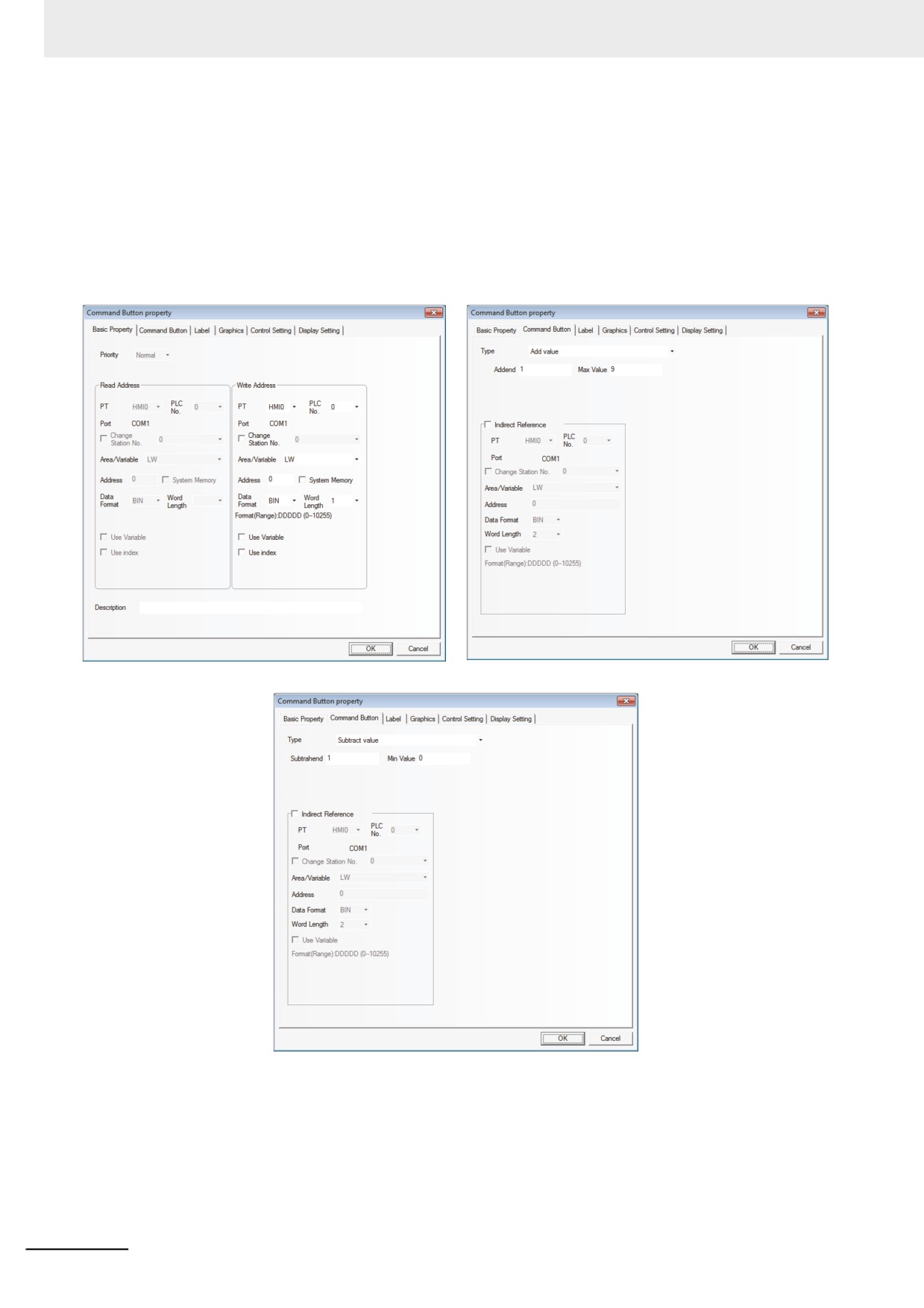
Later, create another two Command Button components with address of LW0 for both of them,
and Setting Mode of “Subtract value” and “Add value” respectively. And no graphics is needed.
Overlay the component of “Add value” on “Down” button which was created at the step 4.
Overlay the component of “Subtract Value” on “Up” button which was created at step 4. The
value of LW0 will vary accordingly, and it will display the group where the current recipe data
locate, as shown below:
3-352