Cisco Industrial Ethernet 4000, 4010 and 5000 Switch Software. Configuration Guide (2022) - page 20

Configuring SPAN and RSPAN
Additional References
Switch(config)# monitor session 1 source interface gigabitEthernet 1/13 - 24
Switch(config)# monitor session 1 destination remote vlan 4
Switch(config)# monitor session 1 timestamp
Switch(config)# end
Additional References
The following sections provide references related to switch administration:
Related Documents
Related Topic
Document Title
Cisco IOS basic commands
Cisco IOS Configuration Fundamentals Command Reference
Standards
Standards
Title
No new or modified standards are supported by this
—
feature, and support for existing standards has not
been modified by this feature.
MIBs
MIBs
MIBs Link
—
To locate and download MIBs using Cisco IOS XR software, use the
Cisco MIB Locator found at the following URL and choose a platform
under the Cisco Access Products menu:
RFCs
RFCs
Title
No new or modified RFCs are supported by this
—
feature, and support for existing RFCs has not been
modified by this feature.
516
Configuring LLDP, LLDP-MED, and Wired
Location Service
Information About LLDP, LLDP-MED, and Wired Location Service
The Cisco Discovery Protocol (CDP) is a device discovery protocol that runs over Layer 2 (the data link layer) on all
Cisco-manufactured devices (routers, bridges, access servers, and switches). CDP allows network management
applications to automatically discover and learn about other Cisco devices connected to the network.
To support non-Cisco devices and to allow for interoperability between other devices, the switch supports the IEEE
802.1AB Link Layer Discovery Protocol (LLDP). LLDP is a neighbor discovery protocol that is used for network devices
to advertise information about themselves to other devices on the network. This protocol runs over the data-link layer,
which allows two systems running different network layer protocols to learn about each other.
LLDP supports a set of attributes that it uses to discover neighbor devices. These attributes contain type, length, and
value descriptions and are referred to as TLVs. LLDP supported devices can use TLVs to receive and send information
to their neighbors. This protocol can advertise details such as configuration information, device capabilities, and device
identity.
The switch supports these basic management TLVs. These are mandatory LLDP TLVs.
Port description TLV
System name TLV
System description TLV
System capabilities TLV
Management address TLV
These organizationally specific LLDP TLVs are also advertised to support LLDP-MED:
Port VLAN ID TLV ((IEEE 802.1 organizationally specific TLVs)
MAC/PHY configuration/status TLV(IEEE 802.3 organizationally specific TLVs)
Note: A switch stack appears as a single switch in the network. Therefore, LLDP discovers the switch stack, not the
individual stack members.
LLDP-MED
LLDP for Media Endpoint Devices (LLDP-MED) is an extension to LLDP that operates between endpoint devices such as
IP phones and network devices such as switches. It specifically provides support for voice over IP (VoIP) applications and
provides additional TLVs for capabilities discovery, network policy, Power over Ethernet, inventory management and
location information. By default, all LLDP-MED TLVs are enabled.
LLDP-MED supports these TLVs:
517
Configuring LLDP, LLDP-MED, and Wired Location Service
Information About LLDP, LLDP-MED, and Wired Location Service
LLDP-MED capabilities TLV
Allows LLDP-MED endpoints to determine the capabilities that the connected device supports and has enabled.
Network policy TLV
Allows both network connectivity devices and endpoints to advertise VLAN configurations and associated Layer 2
and Layer 3 attributes for the specific application on that port. For example, the switch can notify a phone of the
VLAN number that it should use. The phone can connect to any switch, obtain its VLAN number, and then start
communicating with the call control.
By defining a network-policy profile TLV, you can create a profile for voice and voice-signalling by specifying the
values for VLAN, class of service (CoS), differentiated services code point (DSCP), and tagging mode. These profile
attributes are then maintained centrally on the switch and propagated to the phone.
Power management TLV
Enables advanced power management between LLDP-MED endpoint and network connectivity devices. Allows
switches and phones to convey power information, such as how the device is powered, power priority, and how
much power the device needs.
Inventory management TLV
Allows an endpoint to send detailed inventory information about itself to the switch, including information hardware
revision, firmware version, software version, serial number, manufacturer name, model name, and asset ID TLV.
Location TLV
Provides location information from the switch to the endpoint device. The location TLV can send this information:
— Civic location information
Provides the civic address information and postal information. Examples of civic location information are street
address, road name, and postal community name information.
— ELIN location information
Provides the location information of a caller. The location is determined by the emergency location identifier
number (ELIN), which is a phone number that routes an emergency call to the local public safety answering point
(PSAP) and which the PSAP can use to call back the emergency caller.
Wired Location Service
The switch uses the wired location service feature to send location and attachment tracking information for its connected
devices to a Cisco Mobility Services Engine (MSE). The tracked device can be a wireless endpoint, a wired endpoint, or
a wired switch or controller. The switch notifies the MSE of device link up and link down events through the Network
Mobility Services Protocol (NMSP) location and attachment notifications.
The MSE starts the NMSP connection to the switch, which opens a server port. When the MSE connects to the switch
there are a set of message exchanges to establish version compatibility and service exchange information followed by
location information synchronization. After connection, the switch periodically sends location and attachment
notifications to the MSE. Any link up or link down events detected during an interval are aggregated and sent at the end
of the interval.
When the switch determines the presence or absence of a device on a link-up or link-down event, it obtains the
client-specific information such as the MAC address, IP address, and username. If the client is LLDP-MED- or
CDP-capable, the switch obtains the serial number and UDI through the LLDP-MED location TLV or CDP.
Depending on the device capabilities, the switch obtains this client information at link up:
Slot and port specified in port connection
518
Configuring LLDP, LLDP-MED, and Wired Location Service
Information About LLDP, LLDP-MED, and Wired Location Service
MAC address specified in the client MAC address
IP address specified in port connection
802.1X username if applicable
Device category is specified as a wired station
State is specified as new
Serial number, UDI
Model number
Time in seconds since the switch detected the association
Depending on the device capabilities, the switch obtains this client information at link down:
Slot and port that was disconnected
MAC address
IP address
802.1X username if applicable
Device category is specified as a wired station
State is specified as delete
Serial number, UDI
Time in seconds since the switch detected the disassociation
When the switch shuts down, it sends an attachment notification with the state delete and the IP address before closing
the NMSP connection to the MSE. The MSE interprets this notification as disassociation for all the wired clients
associated with the switch.
If you change a location address on the switch, the switch sends an NMSP location notification message that identifies
the affected ports and the changed address information.
519

Configuring LLDP, LLDP-MED, and Wired Location Service
Information About LLDP, LLDP-MED, and Wired Location Service
Default LLDP Configuration
Feature
Default Setting
LLDP global state
Disabled.
LLDP holdtime (before discarding)
120 seconds.
LLDP timer (packet update frequency)
30 seconds.
LLDP reinitialization delay
2 seconds.
LLDP tlv-select
Disabled to send and receive all TLVs.
LLDP interface state
Disabled.
LLDP receive
Disabled.
LLDP transmit
Disabled.
LLDP med-tlv-select
Disabled to send all LLDP-MED TLVs. When LLDP is
globally enabled, LLDP-MED-TLV is also enabled.
LLDP, LLDP-MED, and Wired Location Service Configuration Guidelines
If the interface is configured as a tunnel port, LLDP is automatically disabled.
If you first configure a network-policy profile on an interface, you cannot apply the switchport voice vlan command
on the interface. If the switchport voice vlan vlan-id is already configured on an interface, you can apply a
network-policy profile on the interface. This way the interface has the voice or voice-signaling VLAN network-policy
profile applied on the interface.
You cannot configure static secure MAC addresses on an interface that has a network-policy profile.
You cannot configure a network-policy profile on a private-VLAN port.
For wired location to function, you must first enter the ip device tracking global configuration command.
LLDP-MED TLVs
By default, the switch only sends LLDP packets until it receives LLDP-MED packets from the end device. It then sends
LLDP packets with MED TLVs. When the LLDP-MED entry has been aged out, it only sends LLDP packets.
By using the lldp interface configuration command, you can configure the interface not to send the TLVs listed in this
table.
520

Configuring LLDP, LLDP-MED, and Wired Location Service
How to Configure LLDP, LLDP-MED, and Wired Location Service
LLDP-MED TLV
Description
inventory-management
LLDP-MED inventory management TLV
location
LLDP-MED location TLV
network-policy
LLDP-MED network policy TLV
power-management
LLDP-MED power management TLV
How to Configure LLDP, LLDP-MED, and Wired Location Service
Enabling LLDP
Command
Purpose
1.
configure terminal
Enters global configuration mode.
2.
lldp run
Enables LLDP globally on the switch.
3.
interface interface-id
Specifies the interface on which you are enabling LLDP, and enter
interface configuration mode.
4.
lldp transmit
Enables the interface to send LLDP packets.
5.
lldp receive
Enables the interface to receive LLDP packets.
6.
end
Returns to privileged EXEC mode.
Configuring LLDP Characteristics
You can configure the frequency of LLDP updates, the amount of time to hold the information before discarding it, and
the initialization delay time. You can also select the LLDP and LLDP-MED TLVs to send and receive.
Note: Steps 2 through 5 are optional and can be performed in any order.
Command
Purpose
1.
configure terminal
Enters global configuration mode.
2.
lldp holdtime seconds
(Optional) Specifies the amount of time a receiving device should hold the
information from your device before discarding it.
The range is 0 to 65535 seconds; the default is 120 seconds.
3.
lldp reinit delay
(Optional) Specifies the delay time in seconds for LLDP to initialize on an
interface.
The range is 2 to 5 seconds; the default is 2 seconds.
4.
lldp timer rate
(Optional) Sets the sending frequency of LLDP updates in seconds.
The range is 5 to 65534 seconds; the default is 30 seconds.
5.
lldp tlv-select
(Optional) Specifies the LLDP TLVs to send or receive.
6.
lldp med-tlv-select
(Optional) Specifies the LLDP-MED TLVs to send or receive.
7.
end
Returns to privileged EXEC mode.
521

Configuring LLDP, LLDP-MED, and Wired Location Service
How to Configure LLDP, LLDP-MED, and Wired Location Service
Configuring LLDP-MED TLVs
Command
Purpose
1.
configure terminal
Enters global configuration mode.
2.
interface interface-id
Specifies the interface on which you are configuring an LLDP-MED
TLV, and enters interface configuration mode.
3.
lldp med-tlv-select tlv
Specifies the TLV to enable.
4.
end
Returns to privileged EXEC mode.
Configuring Network-Policy TLV
This task explains how to create a network-policy profile, configure the policy attributes, and apply it to an interface.
Command
Purpose
1.
configure terminal
Enters global configuration mode.
2.
network-policy profile profile number
Specifies the network-policy profile number, and enters
network-policy configuration mode. The range is 1 to 4294967295.
3.
{voice | voice-signaling} vlan [vlan-id
Configures the policy attributes:
{cos cvalue | dscp dvalue}] | [[dot1p
{cos cvalue | dscp dvalue}] | none |
voice—Specifies the voice application type.
untagged]
voice-signaling—Specifies the voice-signaling application type.
vlan—Specifies the native VLAN for voice traffic.
vlan-id—(Optional) Specifies the VLAN for voice traffic. The range is
1 to 4096.
cos cvalue—(Optional) Specifies the Layer 2 priority class of service
(CoS) for the configured VLAN. The range is 0 to 7; the default is 0.
dscp dvalue—(Optional) Specifies the differentiated services code
point (DSCP) value for the configured VLAN. The range is 0 to 63; the
default is 0.
dot1p—(Optional) Configures the telephone to use IEEE 802.1p
priority tagging and use VLAN 0 (the native VLAN).
none—(Optional) Does not instruct the IP telephone about the voice
VLAN. The telephone uses the configuration from the telephone key
pad.
untagged—(Optional) Configures the telephone to send untagged
voice traffic. This is the default for the telephone.
4.
exit
Returns to global configuration mode.
5.
interface interface-id
Specifies the interface on which you are configuring a network-policy
profile, and enter interface configuration mode.
6.
network-policy profile number
Specifies the network-policy profile number.
7.
lldp med-tlv-select network-policy
Specifies the network-policy TLV.
8.
end
Returns to privileged EXEC mode.
522

Configuring LLDP, LLDP-MED, and Wired Location Service
How to Configure LLDP, LLDP-MED, and Wired Location Service
Configuring Location TLV and Wired Location Service
This task explains how to configure location information for an endpoint and to apply it to an interface.
Command
Purpose
1.
configure terminal
Enters global configuration mode.
2.
location {admin-tag string | civic-location
Specifies the location information for an endpoint.
identifier id | elin-location string identifier
id}
admin-tag—Specifies an administrative tag or site information.
civic-location—Specifies civic location information.
elin-location—Specifies emergency location information (ELIN).
identifier id—Specifies the ID for the civic location.
string—Specifies the site or location information in alphanumeric
format.
3.
exit
Returns to global configuration mode.
4.
interface interface-id
Specifies the interface on which you are configuring the location
information, and enters interface configuration mode.
5.
location {additional-location-information
Enters location information for an interface:
word | civic-location-id id |
elin-location-id id}
additional-location-information—Specifies additional information
for a location or place.
civic-location-id—Specifies global civic location information for an
interface.
elin-location-id—Specifies emergency location information for an
interface.
id—Specifies the ID for the civic location or the ELIN location. The ID
range is 1 to 4095.
word—Specifies a word or phrase with additional location
information.
6.
end
Returns to privileged EXEC mode.
7.
nmsp enable
Enables the NMSP features on the switch.
8.
nmsp notification interval {attachment |
Specifies the NMSP notification interval.
location} interval-seconds
attachment—Specifies the attachment notification interval.
location—Specifies the location notification interval.
interval-seconds—Duration in seconds before the switch sends the
MSE the location or attachment updates. The range is 1 to 30; the
default is 30.
9.
end
Returns to privileged EXEC mode.
523

Configuring LLDP, LLDP-MED, and Wired Location Service
Monitoring and Maintaining LLDP, LLDP-MED, and Wired Location Service
Monitoring and Maintaining LLDP, LLDP-MED, and Wired
Location Service
Command
Description
clear lldp counters
Resets the traffic counters to zero.
clear lldp table
Deletes the LLDP neighbor information table.
clear nmsp statistics
Clears the NMSP statistic counters.
show lldp
Displays global information, such as frequency of transmissions, the holdtime for
packets being sent, and the delay time before LLDP initializes on an interface.
show lldp entry entry-name
Displays information about a specific neighbor.
You can enter an asterisk (*) to display all neighbors, or you can enter the
neighbor name.
show lldp interface [interface-id]
Displays information about interfaces with LLDP enabled.
You can limit the display to a specific interface.
show lldp neighbors [interface-id]
Displays information about neighbors, including device type, interface type and
[detail]
number, holdtime settings, capabilities, and port ID.
You can limit the display to neighbors of a specific interface or expand the display
for more detailed information.
show lldp traffic
Displays LLDP counters, including the number of packets sent and received,
number of packets discarded, and number of unrecognized TLVs.
show location admin-tag string
Displays the location information for the specified administrative tag or site.
show location civic-location identifier
Displays the location information for a specific global civic location.
id
show location elin-location identifier id
Displays the location information for an emergency location.
show network-policy profile
Displays the configured network-policy profiles.
show nmsp
Displays the NMSP information.
Configuration Examples for Configuring LLDP, LLDP-MED, and
Wired Location Service
Enabling LLDP: Examples
This example shows how to globally enable LLDP:
Switch# configure terminal
Switch(config)# lldp run
Switch(config)# end
This example shows how to enable LLDP on an interface:
Switch# configure terminal
Switch(config)# interface GigabitEthernet1/17
Switch(config-if)# lldp transmit
Switch(config-if)# lldp receive
Switch(config-if)# end
524
Configuring LLDP, LLDP-MED, and Wired Location Service
Configuration Examples for Configuring LLDP, LLDP-MED, and Wired Location Service
Configuring LDP Parameters: Examples
This example shows how to configure LLDP parameters:
Switch# configure terminal
Switch(config)# lldp holdtime 120
Switch(config)# lldp reinit 2
Switch(config)# lldp timer 30
Switch(config)# end
Configuring TLV: Example
This example shows how to enable a TLV on an interface:
Switch# configure terminal
Switch(config)# interface GigabitEthernet1/17
Switch(config-if)# lldp med-tlv-select inventory-management
Switch(config-if)# end
Configuring Network Policy: Example
This example shows how to configure VLAN 100 for voice application with CoS and to enable the network-policy profile
and network-policy TLV on an interface:
Switch# configure terminal
Switch(config)# network-policy profile 1
Switch(config-network-policy)# voice vlan 100 cos 4
Switch(config-network-policy)# exit
Switch(config)# interface GigabitEthernet1/17
Switch(config-if)# network-policy profile 1
Switch(config-if)# lldp med-tlv-select network-policy
Configuring Voice Application: Example
This example shows how to configure the voice application type for the native VLAN with priority tagging:
Switch(config-network-policy)# voice vlan dot1p cos 4
Switch(config-network-policy)# voice vlan dot1p dscp 34
Configuring Civic Location Information: Example
This example shows how to configure civic location information on the switch:
Switch(config)# location civic-location identifier 1
Switch(config-civic)# number 3550
Switch(config-civic)# primary-road-name "Cisco Way"
Switch(config-civic)# city "San Jose"
Switch(config-civic)# state CA
Switch(config-civic)# building 19
Switch(config-civic)# room C6
Switch(config-civic)# county "Santa Clara"
Switch(config-civic)# country US
Switch(config-civic)# end
525

Configuring LLDP, LLDP-MED, and Wired Location Service
Additional References
Enabling NMSP: Example
This example shows how to enable NMSP on a switch and to set the location notification time to 10 seconds:
Switch(config)# nmsp enable
Switch(config)# nmsp notification interval location 10
Additional References
The following sections provide references related to switch administration:
Related Documents
Related Topic
Document Title
Cisco IOS basic commands
Cisco IOS Configuration Fundamentals Command Reference
Cisco IOS system management commands
Standards
Standards
Title
No new or modified standards are supported by this
—
feature, and support for existing standards has not
been modified by this feature.
MIBs
MIBs
MIBs Link
—
To locate and download MIBs using Cisco IOS XR software, use the
Cisco MIB Locator found at the following URL and choose a platform
under the Cisco Access Products menu:
RFCs
RFCs
Title
No new or modified RFCs are supported by this
—
feature, and support for existing RFCs has not been
modified by this feature.
Technical Assistance
Description
Link
The Cisco Technical Support website contains
thousands of pages of searchable technical content,
including links to products, technologies, solutions,
technical tips, and tools. Registered Cisco.com users
can log in from this page to access even more content.
526
Configuring Layer 2 NAT
One-to-one (1:1) Layer 2 Network Address Translation (NAT) is a service that allows the assignment of a unique public
IP address to an existing private IP address (end device), so that the end device can communicate on both the private
and public subnets. This service is configured in a NAT-enabled device and is the public “alias” of the IP address
physically programmed on the end device. This is typically represented by a table in the NAT device.
Layer 2 NAT has two translation tables where private-to-public and public-to-private subnet translations can be defined.
Layer 2 NAT is a hardware based implementation that provides the same high level of (bump-on-the-wire) wire-speed
performance. This implementation also supports multiple VLANs through the NAT boundary for enhanced network
segmentation.
For information about configuring Layer 2 NAT on a Cisco Industrial Ethernet Switch, see Layer 2 NAT Software
Configuration Guide for Cisco Industrial Ethernet Switches.
Note - The IE 4010 and 5000 follow the same rules documented in the Layer 2 Nat guide.
527
Configuring CDP
Information About CDP
CDP
CDP is a device discovery protocol that runs over Layer 2 (the data link layer) on all Cisco-manufactured devices (routers,
bridges, access servers, and switches) and allows network management applications to discover Cisco devices that are
neighbors of already known devices. With CDP, network management applications can learn the device type and the
Simple Network Management Protocol (SNMP) agent address of neighboring devices running lower-layer, transparent
protocols. This feature enables applications to send SNMP queries to neighboring devices.
CDP runs on all media that support Subnetwork Access Protocol (SNAP). Because CDP runs over the data-link layer only,
two systems that support different network-layer protocols can learn about each other.
Each CDP-configured device sends periodic messages to a multicast address, advertising at least one address at which
it can receive SNMP messages. The advertisements also contain time-to-live, or holdtime information, which is the
length of time a receiving device holds CDP information before discarding it. Each device also listens to the messages
sent by other devices to learn about neighboring devices.
On the switch, CDP enables Network Assistant to display a graphical view of the network. The switch uses CDP to find
cluster candidates and maintain information about cluster members and other devices up to three cluster-enabled
devices away from the command switch by default.
For a switch and connected endpoint devices running Cisco Medianet, these events occur:
CDP identifies connected endpoints that communicate directly with the switch.
Only one wired switch reports the location information to prevent duplicate reports of neighboring devices.
The wired switch and the endpoints both send and receive location information.
The switch supports CDP Version 2.
529

Configuring CDP
How to Configure CDP
Default CDP Configuration
Feature
Default Setting
CDP global state
Enabled
CDP interface state
Enabled
CDP timer (packet update frequency)
60 seconds
CDP holdtime (before discarding)
180 seconds
CDP Version-2 advertisements
Enabled
How to Configure CDP
Configuring the CDP Parameters
You can configure the frequency of CDP updates, the amount of time to hold the information before discarding it, and
whether or not to send Version-2 advertisements.
Note: Steps 2 through 4 are all optional and can be performed in any order.
Command
Purpose
1.
configure terminal
Enters global configuration mode.
2.
cdp timer seconds
(Optional) Sets the transmission frequency of CDP updates in seconds.
The range is 5 to 254; the default is 60 seconds.
3.
cdp holdtime seconds
(Optional) Specifies the amount of time a receiving device should hold the
information sent by your device before discarding it.
The range is 10 to 255 seconds; the default is 180 seconds.
4.
cdp advertise-v2
(Optional) Configures CDP to send Version-2 advertisements.
This is the default state.
5.
end
Returns to privileged EXEC mode.
Disabling CDP
CDP is enabled by default.
Note: Switch clusters and other Cisco devices (such as Cisco IP Phones) regularly exchange CDP messages. Disabling
CDP can interrupt cluster discovery and device connectivity.
530

Configuring CDP
Monitoring and Maintaining CDP
Command
Purpose
1.
configure terminal
Enters global configuration mode.
2.
no cdp run
Disables CDP globally.
3.
interface interface-id
Specifies the interface on which you are disabling CDP, and enters
interface configuration mode.
4.
no cdp enable
Disables CDP on the interface.
5.
end
Returns to privileged EXEC mode.
Monitoring and Maintaining CDP
Command
Description
clear cdp counters
Resets the traffic counters to zero.
clear cdp table
Deletes the CDP table of information about neighbors.
show cdp
Displays global information, such as frequency of transmissions and the holdtime
for packets being sent.
show cdp entry entry-name
Displays information about a specific neighbor.
[protocol | version]
You can enter an asterisk (*) to display all CDP neighbors, or you can enter the
name of the neighbor about which you want information.
You can also limit the display to information about the protocols enabled on the
specified neighbor or information about the version of software running on the
device.
show cdp interface [interface-id]
Displays information about interfaces where CDP is enabled.
You can limit the display to the interface about which you want information.
show cdp neighbors [interface-id]
Displays information about neighbors, including device type, interface type and
[detail]
number, holdtime settings, capabilities, platform, and port ID.
You can limit the display to neighbors of a specific interface or expand the display
to provide more detailed information.
show cdp traffic
Displays CDP counters, including the number of packets sent and received and
checksum errors.
Configuration Examples for CDP
Configuring CDP Parameters: Example
This example shows how to configure CDP parameters:
Switch# configure terminal
Switch(config)# cdp timer 50
Switch(config)# cdp holdtime 120
Switch(config)# cdp advertise-v2
Switch(config)# end
531

Configuring CDP
Additional References
Enabling CDP: Examples
This example shows how to enable CDP on a port when it has been disabled:
Switch# configure terminal
Switch(config)# interface GigabitEthernet1/17
Switch(config-if)# cdp enable
Switch(config-if)# end
Note: Voice VLAN is not counted against port security when CDP is disabled on the switch interface.
This example shows how to enable CDP if it has been disabled:
Switch# configure terminal
Switch(config)# cdp run
Switch(config)# end
Additional References
The following sections provide references related to switch administration:
Related Documents
Related Topic
Document Title
Cisco IOS basic commands
Cisco IOS Configuration Fundamentals Command Reference
Cisco IOS system management commands
Switch cluster configuration
Configuring Switch Clusters, page 91
Standards
Standards
Title
No new or modified standards are supported by this
—
feature, and support for existing standards has not
been modified by this feature.
MIBs
MIBs
MIBs Link
—
To locate and download MIBs using Cisco IOS XR software, use the
Cisco MIB Locator found at the following URL and choose a platform
under the Cisco Access Products menu:
RFCs
RFCs
Title
No new or modified RFCs are supported by this
—
feature, and support for existing RFCs has not been
modified by this feature.
532
Configuring UDLD
Prerequisites for UDLD
When configuring the mode (normal or aggressive), make sure that the same mode is configured on both sides of
the link.
Restrictions for UDLD
UDLD is not supported on ATM ports.
A UDLD-capable port cannot detect a unidirectional link if it is connected to a UDLD-incapable port of another
switch.
Loop guard works only on point-to-point links. We recommend that each end of the link has a directly connected
device that is running STP.
Information About UDLD
UDLD
UniDirectional Link Detection (UDLD) is a Layer 2 protocol that enables devices connected through fiber-optic or
twisted-pair Ethernet cables to monitor the physical configuration of the cables and detect when a unidirectional link
exists. All connected devices must support UDLD for the protocol to successfully identify and disable unidirectional links.
When UDLD detects a unidirectional link, it disables the affected port and alerts you. Unidirectional links can cause a
variety of problems, including spanning-tree topology loops.
Modes of Operation
UDLD supports two modes of operation: normal (the default) and aggressive. In normal mode, UDLD can detect
unidirectional links due to misconnected ports on fiber-optic connections. In aggressive mode, UDLD can also detect
unidirectional links due to one-way traffic on fiber-optic and twisted-pair links and to misconnected ports on fiber-optic
links.
In normal and aggressive modes, UDLD works with the Layer 1 mechanisms to learn the physical status of a link. At Layer
1, autonegotiation takes care of physical signaling and fault detection. UDLD performs tasks that autonegotiation cannot
perform, such as detecting the identities of neighbors and shutting down misconnected ports. When you enable both
autonegotiation and UDLD, the Layer 1 and Layer 2 detections work together to prevent physical and logical unidirectional
connections and the malfunctioning of other protocols.
A unidirectional link occurs whenever traffic sent by a local device is received by its neighbor but traffic from the neighbor
is not received by the local device.
533
Configuring UDLD
Information About UDLD
In normal mode, UDLD detects a unidirectional link when fiber strands in a fiber-optic port are misconnected and the
Layer 1 mechanisms do not detect this misconnection. If the ports are connected correctly but the traffic is one way,
UDLD does not detect the unidirectional link because the Layer 1 mechanism, which is supposed to detect this condition,
does not do so. In this case, the logical link is considered undetermined, and UDLD does not disable the port.
When UDLD is in normal mode, if one of the fiber strands in a pair is disconnected, as long as autonegotiation is active,
the link does not stay up because the Layer 1 mechanisms detects a physical problem with the link. In this case, UDLD
does not take any action and the logical link is considered undetermined.
In aggressive mode, UDLD detects a unidirectional link by using the previous detection methods. UDLD in aggressive
mode can also detect a unidirectional link on a point-to-point link on which no failure between the two devices is allowed.
It can also detect a unidirectional link when one of these problems exists:
On fiber-optic or twisted-pair links, one of the ports cannot send or receive traffic.
On fiber-optic or twisted-pair links, one of the ports is down while the other is up.
One of the fiber strands in the cable is disconnected.
In these cases, UDLD disables the affected port.
In a point-to-point link, UDLD hello packets can be considered as a heart beat whose presence guarantees the health
of the link. Conversely, the loss of the heart beat means that the link must be shut down if it is not possible to reestablish
a bidirectional link.
If both fiber strands in a cable are working normally from a Layer 1 perspective, UDLD in aggressive mode detects
whether those fiber strands are connected correctly and whether traffic is flowing bidirectionally between the correct
neighbors. This check cannot be performed by autonegotiation because autonegotiation operates at Layer 1.
Methods to Detect Unidirectional Links
UDLD operates by using two methods:
Neighbor database maintenance
UDLD learns about other UDLD-capable neighbors by periodically sending a hello packet (also called an
advertisement or probe) on every active port to keep each device informed about its neighbors.
When the switch receives a hello message, it caches the information until the age time (hold time or time-to-live)
expires. If the switch receives a new hello message before an older cache entry ages, the switch replaces the older
entry with the new one.
Whenever a port is disabled and UDLD is running, whenever UDLD is disabled on a port, or whenever the switch is
reset, UDLD clears all existing cache entries for the ports affected by the configuration change. UDLD sends at least
one message to inform the neighbors to flush the part of their caches affected by the status change. The message
is intended to keep the caches synchronized.
Event-driven detection and echoing
UDLD relies on echoing as its detection mechanism. Whenever a UDLD device learns about a new neighbor or
receives a resynchronization request from an out-of-sync neighbor, it restarts the detection window on its side of
the connection and sends echo messages in reply. Because this behavior is the same on all UDLD neighbors, the
sender of the echoes expects to receive an echo in reply.
If the detection window ends and no valid reply message is received, the link might shut down, depending on the
UDLD mode. When UDLD is in normal mode, the link might be considered undetermined and might not be shut down.
When UDLD is in aggressive mode, the link is considered unidirectional, and the port is disabled.
If UDLD in normal mode is in the advertisement or in the detection phase and all the neighbor cache entries are aged
out, UDLD restarts the link-up sequence to resynchronize with any potentially out-of-sync neighbors.
534
Configuring UDLD
How to Configure UDLD
If you enable aggressive mode when all the neighbors of a port have aged out either in the advertisement or in the
detection phase, UDLD restarts the link-up sequence to resynchronize with any potentially out-of-sync neighbor. UDLD
shuts down the port if, after the fast train of messages, the link state is still undetermined.
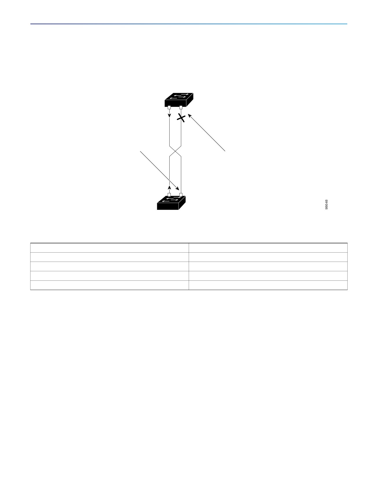
Figure 71
UDLD Detection of a Unidirectional Link
Switch A
TX
RX
Switch B successfully
receives traffic from
Switch A on this port.
However, Switch A does not receive traffic
from Switch B on the same port. If UDLD
is in aggressive mode, it detects the
problem and disables the port. If UDLD is
in normal mode, the logical link is
considered undetermined, and UDLD
does not disable the interface.
TX
RX
Switch B
Default UDLD Settings
Feature
Default Setting
UDLD global enable state
Globally disabled
UDLD per-port enable state for fiber-optic media
Disabled on all Ethernet fiber-optic ports
UDLD per-port enable state for twisted-pair (copper) media
Disabled on all Ethernet 10/100 and 1000BASE-TX ports
UDLD aggressive mode
Disabled
How to Configure UDLD
Enabling UDLD Globally
Follow these steps to enable UDLD in the aggressive or normal mode and to set the configurable message timer on all
fiber-optic ports on the switch:
535

Configuring UDLD
How to Configure UDLD
Command
Purpose
1.
configure terminal
Enters global configuration mode.
2.
udld {aggressive | enable | message
Specifies the UDLD mode of operation:
time message-timer-interval}
aggressive—Enables UDLD in aggressive mode on all fiber-optic
ports.
enable—Enables UDLD in normal mode on all fiber-optic ports on
the switch. UDLD is disabled by default.
An individual interface configuration overrides the setting of the
udld enable global configuration command.
For more information about aggressive and normal modes, see
Modes of Operation, page 533.
message time message-timer-interval—Configures the period of
time between UDLD probe messages on ports that are in the
advertisement phase and are detected to be bidirectional. The
range is from 1 to 90 seconds.
Note: This command affects fiber-optic ports only. Use the udld
interface configuration command to enable UDLD on other port types.
For more information, see Enabling UDLD on an Interface, page 536.
3.
end
Returns to privileged EXEC mode.
Enabling UDLD on an Interface
Command
Purpose
1.
configure terminal
Enters global configuration mode.
2.
interface interface-id
Specifies the port to be enabled for UDLD, and enters interface
configuration mode.
3.
udld port [aggressive]
UDLD is disabled by default.
udld port—Enables UDLD in normal mode on the specified port.
udld port aggressive—Enables UDLD in aggressive mode on the
specified port.
Note: Use the no udld port interface configuration command to disable
UDLD on a specified fiber-optic port.
For more information about aggressive and normal modes, see
Modes of Operation, page 533.
4.
end
Returns to privileged EXEC mode.
536

Configuring UDLD
Maintaining and Monitoring UDLD
Setting and Resetting UDLD Parameters
Command
Purpose
1.
configure terminal
Enters global configuration mode.
2.
udld reset
(Optional) Resets all ports disabled by UDLD.
3.
no udld {aggressive | enable}
(Optional) Disables the UDLD ports.
4.
udld {aggressive | enable}
(Optional) Reenables the disabled ports.
5.
errdisable recovery cause udld
(Optional) Enables the timer to automatically recover from the UDLD
error-disabled state.
6.
errdisable recovery interval interval
(Optional) Specifies the time to recover from the UDLD error-disabled
state.
7.
interface interface-id
Enters interface configuration mode.
8.
no udld port
(Optional) Disables the UDLD fiber-optic port.
9.
udld port [aggressive]
(Optional) Re-enables the disabled fiber-optic port.
10.
shutdown
(Optional) Disables an interface port.
11.
no shutdown
(Optional) Restarts a disabled port.
12.
show udld
(Optional) Verifies your entries.
Maintaining and Monitoring UDLD
Command
Purpose
show udld [interface-id]
Displays UDLD status.
Additional References
The following sections provide references related to switch administration:
537

Configuring UDLD
Additional References
Related Documents
Related Topic
Document Title
Cisco IOS basic commands
Cisco IOS Configuration Fundamentals Command Reference
Standards
Standards
Title
No new or modified standards are supported by this
—
feature, and support for existing standards has not
been modified by this feature.
MIBs
MIBs
MIBs Link
—
To locate and download MIBs using Cisco IOS XR software, use the
Cisco MIB Locator found at the following URL and choose a platform
under the Cisco Access Products menu:
RFCs
RFCs
Title
No new or modified RFCs are supported by this
—
feature, and support for existing RFCs has not been
modified by this feature.
Technical Assistance
Description
Link
The Cisco Technical Support website contains
thousands of pages of searchable technical content,
including links to products, technologies, solutions,
technical tips, and tools. Registered Cisco.com users
can log in from this page to access even more content.
538
Configuring RMON
Prerequisites for RMON
You must configure SNMP on the switch to access RMON MIB objects.
We recommend that you use a generic RMON console application on the network management station (NMS) to take
advantage of the RMON network management capabilities.
Restrictions for RMON
64-bit counters are not supported for RMON alarms.
Information About RMON
RMON
RMON is an Internet Engineering Task Force (IETF) standard monitoring specification that allows various network agents
and console systems to exchange network monitoring data. You can use the RMON feature with the Simple Network
Management Protocol (SNMP) agent in the switch to monitor all the traffic flowing among switches on all connected LAN
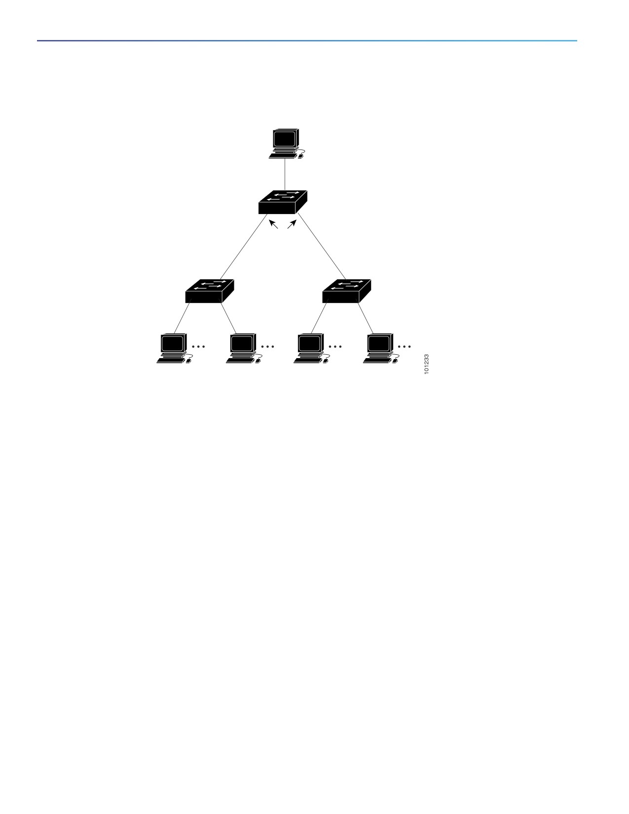
segments as shown in Figure 72 on page 540.
539
Configuring RMON
How to Configure RMON
Figure 72
Remote Monitoring Example
Network management station with
generic RMON console application
RMON alarms and events
configured. SNMP configured.
RMON history
and statistic
collection enabled.
Workstations
Workstations
The switch supports these RMON groups (defined in RFC 1757):
Statistics (RMON group 1)—Collects Ethernet statistics on an interface.
History (RMON group 2)—Collects a history group of statistics on Ethernet ports for a specified polling interval.
Alarm (RMON group 3)—Monitors a specific management information base (MIB) object for a specified interval,
triggers an alarm at a specified value (rising threshold), and resets the alarm at another value (falling threshold).
Alarms can be used with events; the alarm triggers an event, which can generate a log entry or an SNMP trap.
Event (RMON group 9)—Specifies the action to take when an event is triggered by an alarm. The action can be to
generate a log entry or an SNMP trap.
Because switches supported by this software release use hardware counters for RMON data processing, the monitoring
is more efficient, and little processing power is required.
Note: 64-bit counters are not supported for RMON alarms.
RMON is disabled by default; no alarms or events are configured.
How to Configure RMON
Configuring RMON Alarms and Events
You can configure your switch for RMON by using the command-line interface (CLI) or an SNMP-compatible network
management station.
540

Configuring RMON
How to Configure RMON
Command
Purpose
1.
configure terminal
Enters global configuration mode.
2.
rmon alarm number variable interval {absolute | delta}
Sets an alarm on a MIB object.
rising-threshold value [event-number]
falling-threshold value [event-number]
number—Specifies the alarm number. The
range is 1 to 65535.
[owner string]
variable—Specifies the MIB object to monitor.
interval—Specifies the time in seconds the
alarm monitors the MIB variable. The range is 1
to 4294967295 seconds.
Specifies the absolute keyword to test each
MIB variable directly. Specifies the delta
keyword to test the change between samples
of a MIB variable.
value—Specifies a number at which the alarm is
triggered and one for when the alarm is reset.
The range for the rising threshold and falling
threshold values is -2147483648 to
2147483647.
(Optional) event-number—Specifies the event
number to trigger when the rising or falling
threshold exceeds its limit.
(Optional) owner string—Specifies the owner of
the alarm.
3.
rmon event number [description string] [log] [owner string]
Adds an event in the RMON event table that is
[trap community]
associated with an RMON event number.
number—Assigns an event number. The range
is 1 to 65535.
(Optional) description string—Specifies a
description of the event.
(Optional) log—Generates an RMON log entry
when the event is triggered.
(Optional) owner string—Specifies the owner of
this event.
(Optional) trap community—Enters the SNMP
community string used for this trap.
4.
end
Returns to privileged EXEC mode.
Collecting Group History Statistics on an Interface
You must first configure RMON alarms and events to display collection information.
541

Configuring RMON
How to Configure RMON
Command
Purpose
1.
configure terminal
Enters global configuration mode.
2.
interface interface-id
Specifies the interface on which to collect history, and enters
interface configuration mode.
3.
rmon collection history index
Enables history collection for the specified number of buckets
[buckets bucket-number] [interval seconds]
and time period.
[owner ownername]
index—Identifies the RMON group of statistics. The range is
1 to 65535.
(Optional) buckets bucket-number—Specifies the maximum
number of buckets desired for the RMON collection history
group of statistics. The range is 1 to 65535. The default is
50 buckets.
(Optional) interval seconds—Specifies the number of
seconds in each polling cycle. The range is 1 to 3600. The
default is 1800 seconds.
(Optional) owner ownername—Enters the name of the
owner of the RMON group of statistics.
4.
end
Returns to privileged EXEC mode.
Collecting Group Ethernet Statistics on an Interface
Command
Purpose
1.
configure terminal
Enters global configuration mode.
2.
interface interface-id
Specifies the interface on which to collect statistics, and enters
interface configuration mode.
3.
rmon collection stats index [owner
Enables RMON statistic collection on the interface.
ownername]
index—Specifies the RMON group of statistics. The range is
from 1 to 65535.
(Optional) owner ownername—Enters the name of the owner
of the RMON group of statistics.
4.
end
Returns to privileged EXEC mode.
542

Configuring RMON
Monitoring and Maintaining RMON
Monitoring and Maintaining RMON
Command
Purpose
show rmon
Displays general RMON statistics.
show rmon alarms
Displays the RMON alarm table.
show rmon events
Displays the RMON event table.
show rmon history
Displays the RMON history table.
show rmon statistics
Displays the RMON statistics table.
Configuration Examples for RMON
Configuring an RMON Alarm Number: Example
The following example shows how to configure an RMON alarm number:
Switch(config)# rmon alarm 10 ifEntry.20.1 20 delta rising-threshold 15 1 falling-threshold 0 owner
jjohnson
The alarm monitors the MIB variable ifEntry.20.1 once every 20 seconds until the alarm is disabled and checks the change
in the variable’s rise or fall. If the ifEntry.20.1 value shows a MIB counter increase of 15 or more, such as from 100000
to 100015, the alarm is triggered. The alarm in turn triggers event number 1, which is configured with the rmon event
command. Possible events can include a log entry or an SNMP trap. If the ifEntry.20.1 value changes by 0, the alarm is
reset and can be triggered again.
Creating an RMON Event Number: Example
The following example creates RMON event number 1:
Switch(config)# rmon event 1 log trap eventtrap description "High ifOutErrors" owner jjones
The event is defined as High ifOutErrors and generates a log entry when the event is triggered by the alarm. The user
jjones owns the row that is created in the event table by this command. This example also generates an SNMP trap when
the event is triggered.
Configuring RMON Statistics: Example
This example shows how to collect RMON statistics for the owner root:
Switch(config)# interface GigabitEthernet1/17
Switch(config-if)# rmon collection stats 2 owner root
Additional References
The following sections provide references related to switch administration:
543

Configuring RMON
Additional References
Related Documents
Related Topic
Document Title
Cisco IOS basic commands
Cisco IOS Configuration Fundamentals Command Reference
Cisco IOS system management commands
SNMP configuration
Configuring SNMP, page 557
Alarm and event interaction
RFC 1757
Standards
Standards
Title
No new or modified standards are supported by this
—
feature, and support for existing standards has not
been modified by this feature.
MIBs
MIBs
MIBs Link
—
To locate and download MIBs using Cisco IOS XR software, use the
Cisco MIB Locator found at the following URL and choose a platform
under the Cisco Access Products menu:
RFCs
RFCs
Title
No new or modified RFCs are supported by this
—
feature, and support for existing RFCs has not been
modified by this feature.
Technical Assistance
Description
Link
The Cisco Technical Support website contains
thousands of pages of searchable technical content,
including links to products, technologies, solutions,
technical tips, and tools. Registered Cisco.com users
can log in from this page to access even more content.
544
Configuring System Message Logging
Restrictions for System Message Logging
Logging messages to the console at a high rate can result in high CPU utilization and adversely affect how the switch
operates.
Information About System Message Logging
System Message Logging
By default, a switch sends the output from system messages and debug privileged EXEC commands to a logging
process. The logging process controls the distribution of logging messages to various destinations, such as the logging
buffer, terminal lines, or a UNIX syslog server, depending on your configuration. The process also sends messages to the
console.
Note: The syslog format is compatible with 4.3 BSD UNIX.
When the logging process is disabled, messages are sent only to the console. The messages are sent as they are
generated, so message and debug output are interspersed with prompts or output from other commands. Messages
appear on the console after the process that generated them has finished.
You can set the severity level of the messages to control the type of messages displayed on the consoles and each of
the destinations. You can time-stamp log messages or set the syslog source address to enhance real-time debugging
and management.
You can access logged system messages by using the switch command-line interface (CLI) or by saving them to a
properly configured syslog server. The switch software saves syslog messages in an internal buffer.
You can remotely monitor system messages by viewing the logs on a syslog server or by accessing the switch through
Telnet or through the console port.
System Log Message Format
System log messages can contain up to 80 characters and a percent sign (%), which follows the optional sequence
number or time-stamp information, if configured. Messages appear in this format:
seq no:timestamp: %facility-severity-MNEMONIC:description
The part of the message preceding the percent sign depends on the setting of the service sequence-numbers, service
timestamps log datetime, service timestamps log datetime [localtime] [msec] [show-timezone], or service
timestamps log uptime global configuration command.
545

Configuring System Message Logging
Information About System Message Logging
Table 49
System Log Message Elements
Element
Description
seq no:
Stamps log messages with a sequence number only if the service sequence-numbers global
configuration command is configured.
For more information, see Enabling and Disabling Sequence Numbers in Log Messages, page 552.
timestamp formats:
Date and time of the message or event. This information appears only if the service timestamps
log [datetime | log] global configuration command is configured.
mm/dd hh:mm:ss
For more information, see Enabling and Disabling Time Stamps on Log Messages, page 552.
or
hh:mm:ss (short uptime)
or
d h (long uptime)
facility
The facility to which the message refers (for example, SNMP, SYS, and so forth).
severity
Single-digit code from 0 to 7 that is the severity of the message.
MNEMONIC
Text string that uniquely describes the message.
description
Text string containing detailed information about the event being reported.
Log Messages
You can synchronize unsolicited messages and debug privileged EXEC command output with solicited device output and
prompts for a specific console port line or virtual terminal line. You can identify the types of messages to be output
asynchronously based on the level of severity. You can also configure the maximum number of buffers for storing
asynchronous messages for the terminal after which messages are dropped.
When synchronous logging of unsolicited messages and debug command output is enabled, unsolicited device output
appears on the console or printed after solicited device output appears or is printed. Unsolicited messages and debug
command output appears on the console after the prompt for user input is returned. Therefore, unsolicited messages
and debug command output are not interspersed with solicited device output and prompts. After the unsolicited
messages appear, the console again displays the user prompt.
Message Severity Levels
Note: Specifying a level causes messages at that level and numerically lower levels to appear at the destination.
To disable logging to the console, use the no logging console global configuration command. To disable logging to a
terminal other than the console, use the no logging monitor global configuration command. To disable logging to syslog
servers, use the no logging trap global configuration command.
Table 50 on page 547 describes the level keywords. It also lists the corresponding UNIX syslog definitions from the most
severe level to the least severe level.
546