Cisco Industrial Ethernet 4000, 4010 and 5000 Switch Software. Configuration Guide (2022) - page 19

Configuring Port-Based Traffic Control
Monitoring and Maintaining Port-Based Traffic Control
Monitoring and Maintaining Port-Based Traffic Control
Command
Purpose
show interfaces [interface-id] switchport
Displays the administrative and operational status of all switching
(nonrouting) ports or the specified port, including port blocking and port
protection settings.
show storm-control [interface-id] [broadcast |
Displays storm control suppression levels set on all interfaces or the
multicast | unicast]
specified interface for the specified traffic type or for broadcast traffic if
no traffic type is entered.
show port-security [interface interface-id]
Displays port security settings for the switch or for the specified interface,
including the maximum allowed number of secure MAC addresses for
each interface, the number of secure MAC addresses on the interface,
the number of security violations that have occurred, and the violation
mode.
show port-security [interface interface-id]
Displays all secure MAC addresses configured on all switch interfaces or
address
on a specified interface with aging information for each address.
show port-security interface interface-id vlan
Displays the number of secure MAC addresses configured per VLAN on
the specified interface.
show storm-control [interface-id] [broadcast |
Displays the storm control suppression levels set on the interface for the
multicast | unicast]
specified traffic type. If you do not enter a traffic type, broadcast storm
control settings are displayed.
show interfaces interface-id
Displays the interface configuration.
show interfaces interface-id switchport
Displays switch-port information.
show port-security
Displays port-security settings for an interface or for the switch.
show psp config {arp | dhcp | igmp}
Displays PSP configuration details for protocols.
Configuration Examples for Port-Based Traffic Control
Enabling Unicast Storm Control: Example
This example shows how to enable unicast storm control on a port with an 87-percent rising suppression level and a
65-percent falling suppression level:
Switch# configure terminal
Switch(config)# interface gigabitethernet1/1
Switch(config-if)# storm-control unicast level 87 65
Enabling Broadcast Address Storm Control on a Port: Example
This example shows how to enable broadcast address storm control on a port to a level of 20 percent. When the
broadcast traffic exceeds the configured level of 20 percent of the total available bandwidth of the port within the
traffic-storm-control interval, the switch drops all broadcast traffic until the end of the traffic-storm-control interval:
Switch# configure terminal
Switch(config)# interface GigabitEthernet1/17
Switch(config-if)# storm-control broadcast level 20
486
Configuring Port-Based Traffic Control
Configuration Examples for Port-Based Traffic Control
Enabling Small-Frame Arrival Rate: Example
This example shows how to enable the small-frame arrival-rate feature, configure the port recovery time, and configure
the threshold for error-disabling a port:
Switch# configure terminal
Switch# errdisable detect cause small-frame
Switch# errdisable recovery cause small-frame
Switch(config)# interface GigabitEthernet1/17
Switch(config-if)# small-frame violation rate 10000
Switch(config-if)# end
Configuring a Protected Port: Example
This example shows how to configure a port as a protected port:
Switch# configure terminal
Switch(config)# interface GigabitEthernet1/17
Switch(config-if)# switchport protected
Switch(config-if)# end
Blocking Flooding on a Port: Example
This example shows how to block unicast and Layer 2 multicast flooding on a port:
Switch# configure terminal
Switch(config)# interface GigabitEthernet1/17
Switch(config-if)# switchport block multicast
Switch(config-if)# switchport block unicast
Switch(config-if)# end
Configuring Port Security: Examples
This example shows how to enable port security on a port and to set the maximum number of secure addresses to 50.
The violation mode is the default, no static secure MAC addresses are configured, and sticky learning is enabled:
Switch(config)# interface GigabitEthernet1/17
Switch(config-if)# switchport mode access
Switch(config-if)# switchport port-security
Switch(config-if)# switchport port-security maximum 50
Switch(config-if)# switchport port-security mac-address sticky
This example shows how to configure a static secure MAC address on VLAN 3 on a port:
Switch(config)# interface GigabitEthernet1/18
Switch(config-if)# switchport mode trunk
Switch(config-if)# switchport port-security
Switch(config-if)# switchport port-security mac-address 0000.02000.0004 vlan 3
This example shows how to enable sticky port security on a port, to manually configure MAC addresses for data VLAN
and voice VLAN, and to set the total maximum number of secure addresses to 20 (10 for data VLAN and 10 for voice
VLAN).
Switch(config)# interface FastEthernet1/1
Switch(config-if)# switchport access vlan 21
Switch(config-if)# switchport mode access
Switch(config-if)# switchport voice vlan 22
Switch(config-if)# switchport port-security
487
Configuring Port-Based Traffic Control
Additional References
Switch(config-if)# switchport port-security maximum 20
Switch(config-if)# switchport port-security violation restrict
Switch(config-if)# switchport port-security mac-address sticky
Switch(config-if)# switchport port-security mac-address sticky 0000.0000.0002
Switch(config-if)# switchport port-security mac-address 0000.0000.0003
Switch(config-if)# switchport port-security mac-address sticky 0000.0000.0001 vlan voice
Switch(config-if)# switchport port-security mac-address 0000.0000.0004 vlan voice
Switch(config-if)# switchport port-security maximum 10 vlan access
Switch(config-if)# switchport port-security maximum 10 vlan voice
Configuring Port Security Aging: Examples
This example shows how to set the aging time as 2 hours for the secure addresses on a port:
Switch(config)# interface GigabitEthernet1/17
Switch(config-if)# switchport port-security aging time 120
This example shows how to set the aging time as 2 minutes for the inactivity aging type with aging enabled for the
configured secure addresses on the interface:
Switch(config-if)# switchport port-security aging time 2
Switch(config-if)# switchport port-security aging type inactivity
Switch(config-if)# switchport port-security aging static
You can verify the previous commands by entering the show port-security interface interface-id privileged EXEC
command.
Configuring Protocol Storm Protection: Example
This example shows how to configure protocol storm protection to drop incoming DHCP traffic on DHCP when it exceeds
35 packets per second:
Switch# configure terminal
Switch(config)# psp dhcp pps 35
Additional References
The following sections provide references related to switch administration:
488

Configuring Port-Based Traffic Control
Additional References
Related Documents
Related Topic
Document Title
Cisco IOS basic commands
Cisco IOS Configuration Fundamentals Command Reference
Standards
Standards
Title
No new or modified standards are supported by this
—
feature, and support for existing standards has not
been modified by this feature.
MIBs
MIBs
MIBs Link
—
To locate and download MIBs using Cisco IOS XR software, use the
Cisco MIB Locator found at the following URL and choose a platform
under the Cisco Access Products menu:
RFCs
RFCs
Title
No new or modified RFCs are supported by this
—
feature, and support for existing RFCs has not been
modified by this feature.
Technical Assistance
Description
Link
The Cisco Technical Support website contains
thousands of pages of searchable technical content,
including links to products, technologies, solutions,
technical tips, and tools. Registered Cisco.com users
can log in from this page to access even more content.
489
Configuring Port-Based Traffic Control
Additional References
490
Configuring SPAN and RSPAN
Prerequisites for SPAN and RSPAN
You must globally configure the ip device tracking maximum limit-number interface configuration command
globally for IPSG for static hosts to work. If you only configure this command on a port without enabling IP device
tracking globally or setting an IP device tracking maximum on that interface, IPSG with static hosts will reject all the
IP traffic from that interface. This requirement also applies to IPSG with static hosts on a Layer 2 access port.
Information About SPAN and RSPAN
SPAN and RSPAN
You can analyze network traffic passing through ports or VLANs by using Switched Port Analyzer (SPAN) or Remote SPAN
(RSPAN) to send a copy of the traffic to another port on the switch or on another switch that has been connected to a
network analyzer or other monitoring or security device. SPAN copies (or mirrors) traffic received or sent (or both) on
source ports or source VLANs to a destination port for analysis. SPAN does not affect the switching of network traffic on
the source ports or VLANs. You must dedicate the destination port for SPAN use. Except for traffic that is required for
the SPAN or RSPAN session, destination ports do not receive or forward traffic.
Only traffic that enters or leaves source ports or traffic that enters or leaves source VLANs can be monitored by using
SPAN; traffic routed to a source VLAN cannot be monitored. For example, if incoming traffic is being monitored, traffic
that gets routed from another VLAN to the source VLAN cannot be monitored; however, traffic that is received on the
source VLAN and routed to another VLAN can be monitored.
You can use the SPAN or RSPAN destination port to inject traffic from a network security device. For example, if you
connect a Cisco Intrusion Detection System (IDS) sensor appliance to a destination port, the IDS device can send TCP
reset packets to close down the TCP session of a suspected attacker.
Local SPAN
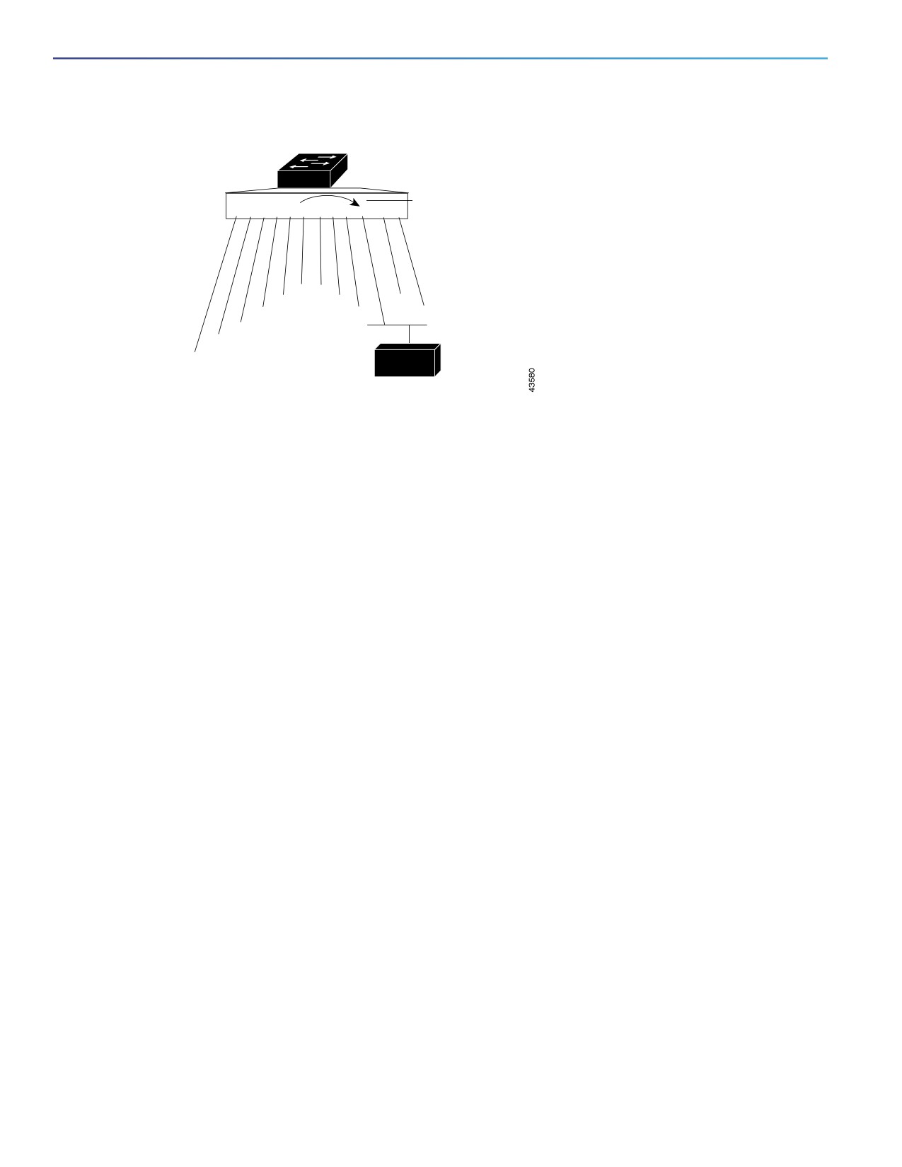
Local SPAN supports a SPAN session entirely within one switch; all source ports or source VLANs and destination ports
are in the same switch. Local SPAN copies traffic from one or more source ports in any VLAN or from one or more VLANs
to a destination port for analysis. For example, in Figure 69 on page 492, all traffic on port 5 (the source port) is mirrored
to port 10 (the destination port). A network analyzer on port 10 receives all network traffic from port 5 without being
physically attached to port 5.
491
Configuring SPAN and RSPAN
Information About SPAN and RSPAN
Figure 69
Example of Local SPAN Configuration on a Single Switch
Port 5 traffic mirrored
1 2 3 4 5 6
7 8 9 10 11 12
on Port 10
6
7
5
8
11
4
9
12
3
10
2
1
Network analyzer
Remote SPAN
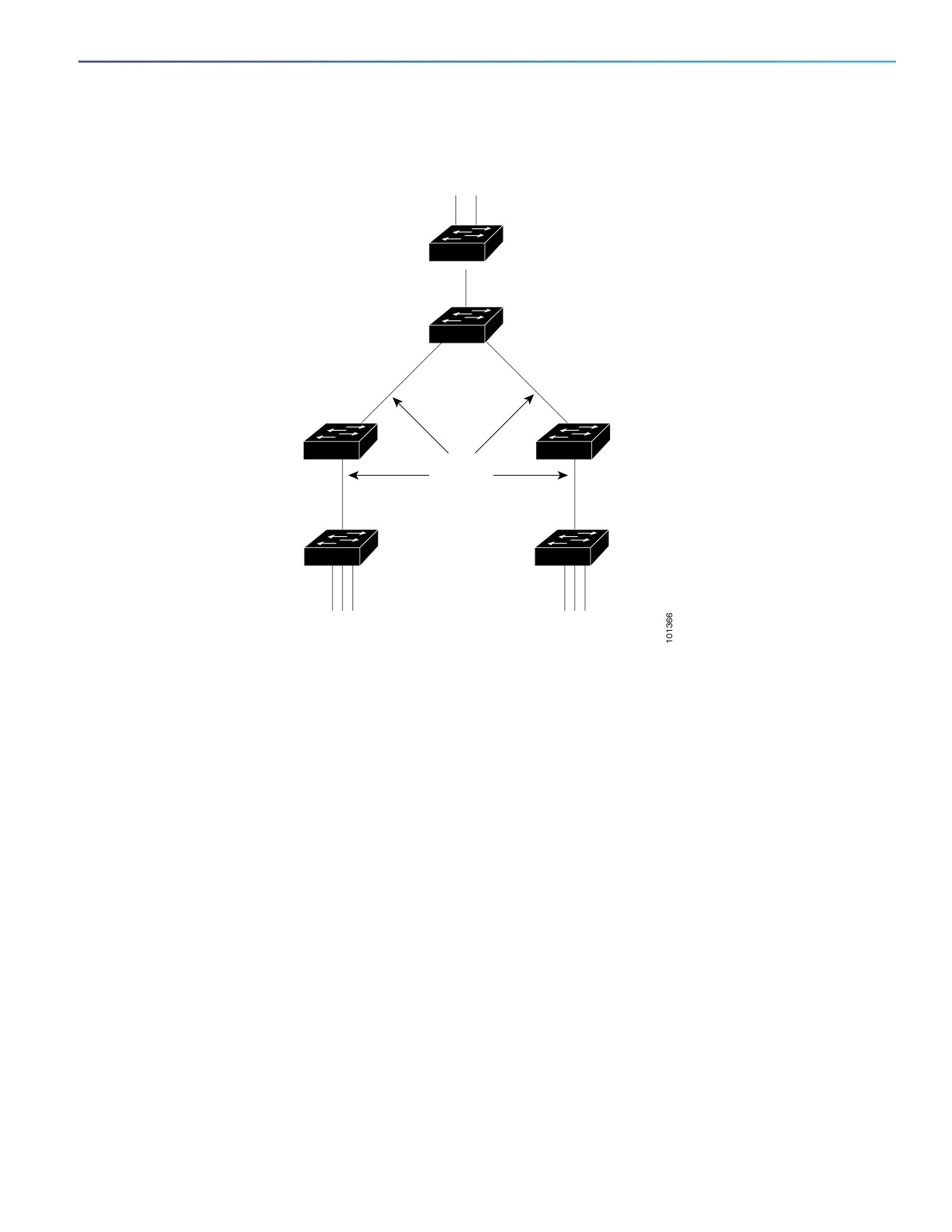
RSPAN supports source ports, source VLANs, and destination ports on different switches, enabling remote monitoring
of multiple switches across your network. Figure 70 on page 493 shows source ports on Switch A and Switch B. The
traffic for each RSPAN session is carried over a user-specified RSPAN VLAN that is dedicated for that RSPAN session in
all participating switches. The RSPAN traffic from the source ports or VLANs is copied into the RSPAN VLAN and
forwarded over trunk ports carrying the RSPAN VLAN to a destination session monitoring the RSPAN VLAN. Each RSPAN
source switch must have either ports or VLANs as RSPAN sources. The destination is always a physical port, as shown
on Switch C in the figure.
492
Configuring SPAN and RSPAN
Information About SPAN and RSPAN
Figure 70
Example of RSPAN Configuration
RSPAN
destination ports
RSPAN
Switch C
destination
session
Intermediate switches
must support RSPAN VLAN
RSPAN
VLAN
Switch A
Switch B
RSPAN
RSPAN
source
source
session A
session B
RSPAN
RSPAN
source ports
source ports
SPAN Sessions
SPAN sessions (local or remote) allow you to monitor traffic on one or more ports, or one or more VLANs, and send the
monitored traffic to one or more destination ports.
A local SPAN session is an association of a destination port with source ports or source VLANs, all on a single network
device. Local SPAN does not have separate source and destination sessions. Local SPAN sessions gather a set of ingress
and egress packets specified by the user and form them into a stream of SPAN data, which is directed to the destination
port.
RSPAN consists of at least one RSPAN source session, an RSPAN VLAN, and at least one RSPAN destination session.
You separately configure RSPAN source sessions and RSPAN destination sessions on different network devices. To
configure an RSPAN source session on a device, you associate a set of source ports or source VLANs with an RSPAN
VLAN. The output of this session is the stream of SPAN packets that are sent to the RSPAN VLAN. To configure an RSPAN
destination session on another device, you associate the destination port with the RSPAN VLAN. The destination session
collects all RSPAN VLAN traffic and sends it out the RSPAN destination port.
An RSPAN source session is very similar to a local SPAN session, except for where the packet stream is directed. In an
RSPAN source session, SPAN packets are relabeled with the RSPAN VLAN ID and directed over normal trunk ports to the
destination switch.
An RSPAN destination session takes all packets received on the RSPAN VLAN, strips off the VLAN tagging, and presents
them on the destination port. Its purpose is to present a copy of all RSPAN VLAN packets (except Layer 2 control packets)
to the user for analysis.
493
Configuring SPAN and RSPAN
Information About SPAN and RSPAN
There can be more than one source session and more than one destination session active in the same RSPAN VLAN.
There can also be intermediate switches separating the RSPAN source and destination sessions. These switches need
not be capable of running RSPAN, but they must respond to the requirements of the RSPAN VLAN (see RSPAN VLAN,
page 497).
Traffic monitoring in a SPAN session has these restrictions:
Sources can be ports or VLANs, but you cannot mix source ports and source VLANs in the same session.
The switch supports up to 4 source sessions (local SPAN and RSPAN source sessions). You can run both a local
SPAN and an RSPAN source session in the same switch. The switch supports a total of 68 source and RSPAN
destination sessions.
You can have multiple destination ports in a SPAN session, but no more than 64 destination ports.
You can configure two separate SPAN or RSPAN source sessions with separate or overlapping sets of SPAN source
ports and VLANs. Both switched and routed ports can be configured as SPAN sources and destinations.
SPAN sessions do not interfere with the normal operation of the switch. However, an oversubscribed SPAN
destination, for example, a 10-Mb/s port monitoring a 100-Mb/s port, can result in dropped or lost packets.
When RSPAN is enabled, each packet being monitored is transmitted twice, once as normal traffic and once as a
monitored packet. Therefore monitoring a large number of ports or VLANs could potentially generate large amounts
of network traffic.
You can configure SPAN sessions on disabled ports; however, a SPAN session does not become active unless you
enable the destination port and at least one source port or VLAN for that session.
The switch does not support a combination of local SPAN and RSPAN in a single session. That is, an RSPAN source
session cannot have a local destination port, an RSPAN destination session cannot have a local source port, and an
RSPAN destination session and an RSPAN source session that are using the same RSPAN VLAN cannot run on the
same switch.
Monitored Traffic Types for SPAN Sessions
Receive (Rx) SPAN—The goal of receive (or ingress) SPAN is to monitor as much as possible all the packets received
by the source interface or VLAN before any modification or processing is performed by the switch. A copy of each
packet received by the source is sent to the destination port for that SPAN session.
Packets that are modified because of routing or quality of service (QoS)—for example, modified Differentiated
Services Code Point (DSCP)—are copied before modification.
Features that can cause a packet to be dropped during receive processing have no effect on ingress SPAN; the
destination port receives a copy of the packet even if the actual incoming packet is dropped. These features include
IP standard and extended input access control lists (ACLs), ingress QoS policing, VLAN ACLs, and egress QoS
policing.
Transmit (Tx) SPAN—The goal of transmit (or egress) SPAN is to monitor as much as possible all the packets sent by
the source interface after all modification and processing is performed by the switch. A copy of each packet sent by
the source is sent to the destination port for that SPAN session. The copy is provided after the packet is modified.
Packets that are modified because of routing—for example, with modified time-to-live (TTL), MAC-address, or QoS
values—are duplicated (with the modifications) at the destination port.
Features that can cause a packet to be dropped during transmit processing also affect the duplicated copy for SPAN.
These features include IP standard and extended output ACLs and egress QoS policing.
Both—In a SPAN session, you can also monitor a port or VLAN for both received and sent packets. This is the default.
494
Configuring SPAN and RSPAN
Information About SPAN and RSPAN
The default configuration for local SPAN session ports is to send all packets untagged. SPAN also does not normally
monitor bridge protocol data unit (BPDU) packets and Layer 2 protocols, such as Cisco Discovery Protocol (CDP), VLAN
Trunk Protocol (VTP), Dynamic Trunking Protocol (DTP), Spanning Tree Protocol (STP), and Port Aggregation Protocol
(PAgP). However, when you enter the encapsulation replicate keywords when configuring a destination port, these
changes occur:
Packets are sent on the destination port with the same encapsulation—untagged or IEEE 802.1Q—that they had on
the source port.
Packets of all types, including BPDU and Layer 2 protocol packets, are monitored.
Therefore, a local SPAN session with encapsulation replicate enabled can have a mixture of untagged and IEEE 802.1Q
tagged packets appear on the destination port.
Switch congestion can cause packets to be dropped at ingress source ports, egress source ports, or SPAN destination
ports. In general, these characteristics are independent of one another. For example:
A packet might be forwarded normally but dropped from monitoring due to an oversubscribed SPAN destination
port.
An ingress packet might be dropped from normal forwarding, but still appear on the SPAN destination port.
An egress packet dropped because of switch congestion is also dropped from egress SPAN.
In some SPAN configurations, multiple copies of the same source packet are sent to the SPAN destination port. For
example, a bidirectional (both Rx and Tx) SPAN session is configured for the Rx monitor on port A and Tx monitor on
port B. If a packet enters the switch through port A and is switched to port B, both incoming and outgoing packets are
sent to the destination port. Both packets are the same (unless a Layer-3 rewrite occurs, in which case the packets are
different because of the packet modification).
Source Ports
A source port (also called a monitored port) is a switched or routed port that you monitor for network traffic analysis. In
a local SPAN session or RSPAN source session, you can monitor source ports or VLANs for traffic in one or both
directions. The switch supports any number of source ports (up to the maximum number of available ports on the switch)
and any number of source VLANs (up to the maximum number of VLANs supported). However, the switch supports a
maximum of two sessions (local or RSPAN) with source ports or VLANs, and you cannot mix ports and VLANs in a single
session.
A source port has these characteristics:
It can be monitored in multiple SPAN sessions.
Each source port can be configured with a direction (ingress, egress, or both) to monitor.
It can be any port type (for example, EtherChannel, Gigabit Ethernet, and so forth).
For EtherChannel sources, you can monitor traffic for the entire EtherChannel or individually on a physical port as it
participates in the port channel.
It can be an access port, trunk port, routed port, or voice VLAN port.
It cannot be a destination port.
Source ports can be in the same or different VLANs.
You can monitor multiple source ports in a single session.
495
Configuring SPAN and RSPAN
Information About SPAN and RSPAN
Source VLANs
VLAN-based SPAN (VSPAN) is the monitoring of the network traffic in one or more VLANs. The SPAN or RSPAN source
interface in VSPAN is a VLAN ID, and traffic is monitored on all the ports for that VLAN.
VSPAN has these characteristics:
All active ports in the source VLAN are included as source ports and can be monitored in either or both directions.
On a given port, only traffic on the monitored VLAN is sent to the destination port.
If a destination port belongs to a source VLAN, it is excluded from the source list and is not monitored.
If ports are added to or removed from the source VLANs, the traffic on the source VLAN received by those ports is
added to or removed from the sources being monitored.
You cannot use filter VLANs in the same session with VLAN sources.
You can monitor only Ethernet VLANs.
VLAN Filtering
When you monitor a trunk port as a source port, by default, all VLANs active on the trunk are monitored. You can limit
SPAN traffic monitoring on trunk source ports to specific VLANs by using VLAN filtering.
VLAN filtering applies only to trunk ports or to voice VLAN ports.
VLAN filtering applies only to port-based sessions and is not allowed in sessions with VLAN sources.
When a VLAN filter list is specified, only those VLANs in the list are monitored on trunk ports or on voice VLAN access
ports.
SPAN traffic coming from other port types is not affected by VLAN filtering; that is, all VLANs are allowed on other
ports.
VLAN filtering affects only traffic forwarded to the destination SPAN port and does not affect the switching of normal
traffic.
Destination Port
Each local SPAN session or RSPAN destination session must have a destination port (also called a monitoring port) that
receives a copy of traffic from the source ports or VLANs and sends the SPAN packets to the user, usually a network
analyzer.
A destination port has these characteristics:
For a local SPAN session, the destination port must reside on the same switch as the source port. For an RSPAN
session, it is located on the switch containing the RSPAN destination session. There is no destination port on a switch
running only an RSPAN source session.
When a port is configured as a SPAN destination port, the configuration overwrites the original port configuration.
When the SPAN destination configuration is removed, the port reverts to its previous configuration. If a configuration
change is made to the port while it is acting as a SPAN destination port, the change does not take effect until the
SPAN destination configuration had been removed.
If the port was in an EtherChannel group, it is removed from the group while it is a destination port. If it was a routed
port, it is no longer a routed port.
It can be any Ethernet physical port.
It cannot be a secure port.
496
Configuring SPAN and RSPAN
Information About SPAN and RSPAN
It cannot be a source port.
It cannot be an EtherChannel group or a VLAN.
It can participate in only one SPAN session at a time (a destination port in one SPAN session cannot be a destination
port for a second SPAN session).
When it is active, incoming traffic is disabled. The port does not transmit any traffic except that required for the SPAN
session. Incoming traffic is never learned or forwarded on a destination port.
If ingress traffic forwarding is enabled for a network security device, the destination port forwards traffic at Layer 2.
It does not participate in any of the Layer 2 protocols (STP, VTP, CDP, DTP, PagP).
A destination port that belongs to a source VLAN of any SPAN session is excluded from the source list and is not
monitored.
The maximum number of destination ports in a switch is 64.
Local SPAN and RSPAN destination ports behave differently regarding VLAN tagging and encapsulation:
For local SPAN, if the encapsulation replicate keywords are specified for the destination port, these packets appear
with the original encapsulation (untaggedor IEEE 802.1Q). If these keywords are not specified, packets appear in the
untagged format. Therefore, the output of a local SPAN session with encapsulation replicate enabled can contain
a mixture of untagged or IEEE 802.1Q-tagged packets.
For RSPAN, the original VLAN ID is lost because it is overwritten by the RSPAN VLAN identification. Therefore, all
packets appear on the destination port as untagged.
RSPAN VLAN
The RSPAN VLAN carries SPAN traffic between RSPAN source and destination sessions. It has these special
characteristics:
All traffic in the RSPAN VLAN is always flooded.
No MAC address learning occurs on the RSPAN VLAN.
RSPAN VLAN traffic only flows on trunk ports.
RSPAN VLANs must be configured in VLAN configuration mode by using the remote-span VLAN configuration mode
command.
STP can run on RSPAN VLAN trunks but not on SPAN destination ports.
An RSPAN VLAN cannot be a private-VLAN primary or secondary VLAN.
For VLANs 1 to 1005 that are visible to VLAN Trunking Protocol (VTP), the VLAN ID and its associated RSPAN
characteristic are propagated by VTP. If you assign an RSPAN VLAN ID in the extended VLAN range (1006 to 4096), you
must manually configure all intermediate switches.
It is normal to have multiple RSPAN VLANs in a network at the same time with each RSPAN VLAN defining a network-wide
RSPAN session. That is, multiple RSPAN source sessions anywhere in the network can contribute packets to the RSPAN
session. It is also possible to have multiple RSPAN destination sessions throughout the network, monitoring the same
RSPAN VLAN and presenting traffic to the user. The RSPAN VLAN ID separates the sessions.
497
Configuring SPAN and RSPAN
Information About SPAN and RSPAN
Spanned Traffic Timestamping (IE 5000 only)
The Spanned Traffic Timestamping feature for IE 5000 switches provides ingress timestamping (timestamping of
received packets) for a single SPAN/RSPAN session. Egress timestamping (timestamping of transmitted packets) is not
supported. Spanned Traffic Timestamping is available in Cisco IOS Release 15.2(7)E1a and later.
Spanned Traffic Timestamping is implemented through the switch hardware, which is synchronized to the PTP
Grandmaster Clock through the IEEE Std 1588-2008 PTP protocol. IE 5000 switch network interfaces connected to
sensor/end devices are configured as SPAN session source interfaces with timestamping enabled. This configuration
results in all ingress packets from sensor/end devices to be timestamped at the IE 5000 timestamping switch network
interface physical layer. The RSPAN VLAN is configured as the SPAN session destination. See Spanned Traffic
Timestamping Configuration Guidelines, page 500, Creating a Local SPAN Session with Timestamp, page 510, and
Creating an RSPAN Source Session with Timestamp, page 512.
SPAN and RSPAN Interaction with Other Features
Routing—SPAN does not monitor routed traffic. VSPAN only monitors traffic that enters or exits the switch, not traffic
that is routed between VLANs. For example, if a VLAN is being Rx-monitored and the switch routes traffic from
another VLAN to the monitored VLAN, that traffic is not monitored and not received on the SPAN destination port.
STP—A destination port does not participate in STP while its SPAN or RSPAN session is active. The destination port
can participate in STP after the SPAN or RSPAN session is disabled. On a source port, SPAN does not affect the STP
status. STP can be active on trunk ports carrying an RSPAN VLAN.
CDP—A SPAN destination port does not participate in CDP while the SPAN session is active. After the SPAN session
is disabled, the port again participates in CDP.
VTP—You can use VTP to prune an RSPAN VLAN between switches.
VLAN and trunking—You can modify VLAN membership or trunk settings for source or destination ports at any time.
However, changes in VLAN membership or trunk settings for a destination port do not take effect until you remove
the SPAN destination configuration. Changes in VLAN membership or trunk settings for a source port immediately
take effect, and the respective SPAN sessions automatically adjust accordingly.
EtherChannel—You can configure an EtherChannel group as a source port but not as a SPAN destination port. When
a group is configured as a SPAN source, the entire group is monitored.
If a physical port is added to a monitored EtherChannel group, the new port is added to the SPAN source port list. If
a port is removed from a monitored EtherChannel group, it is automatically removed from the source port list.
A physical port that belongs to an EtherChannel group can be configured as a SPAN source port and still be a part
of the EtherChannel. In this case, data from the physical port is monitored as it participates in the EtherChannel.
However, if a physical port that belongs to an EtherChannel group is configured as a SPAN destination, it is removed
from the group. After the port is removed from the SPAN session, it rejoins the EtherChannel group. Ports removed
from an EtherChannel group remain members of the group, but they are in the inactive or suspended state.
If a physical port that belongs to an EtherChannel group is a destination port and the EtherChannel group is a source,
the port is removed from the EtherChannel group and from the list of monitored ports.
Multicast traffic can be monitored. For egress and ingress port monitoring, only a single unedited packet is sent to
the SPAN destination port. It does not reflect the number of times the multicast packet is sent.
A private-VLAN port cannot be a SPAN destination port.
A secure port cannot be a SPAN destination port.
For SPAN sessions, do not enable port security on ports with monitored egress when ingress forwarding is enabled
on the destination port. For RSPAN source sessions, do not enable port security on any ports with monitored egress.
498
Configuring SPAN and RSPAN
Information About SPAN and RSPAN
An IEEE 802.1x port can be a SPAN source port. You can enable IEEE 802.1x on a port that is a SPAN destination
port; however, IEEE 802.1x is disabled until the port is removed as a SPAN destination.
For SPAN sessions, do not enable IEEE 802.1x on ports with monitored egress when ingress forwarding is enabled
on the destination port. For RSPAN source sessions, do not enable IEEE 802.1x on any ports that are egress
monitored.
Local SPAN Configuration Guidelines
For SPAN sources, you can monitor traffic for a single port or VLAN or a series or range of ports or VLANs for each
session. You cannot mix source ports and source VLANs within a single SPAN session.
The destination port cannot be a source port; a source port cannot be a destination port.
You cannot have two SPAN sessions using the same destination port.
When you configure a switch port as a SPAN destination port, it is no longer a normal switch port; only monitored
traffic passes through the SPAN destination port.
Entering SPAN configuration commands does not remove previously configured SPAN parameters. You must enter
the no monitor session {session_number | all | local | remote} global configuration command to delete configured
SPAN parameters.
For local SPAN, outgoing packets through the SPAN destination port carry the original encapsulation
headers—untagged or IEEE 802.1Q—if the encapsulation replicate keywords are specified. If the keywords are not
specified, the packets are sent in native form. For RSPAN destination ports, outgoing packets are not tagged.
You can configure a disabled port to be a source or destination port, but the SPAN function does not start until the
destination port and at least one source port or source VLAN are enabled.
You can limit SPAN traffic to specific VLANs by using the filter vlan keyword. If a trunk port is being monitored, only
traffic on the VLANs specified with this keyword is monitored. By default, all VLANs are monitored on a trunk port.
You cannot mix source VLANs and filter VLANs within a single SPAN session.
RSPAN Configuration Guidelines
All the items in the Local SPAN Configuration Guidelines, page 499 apply to RSPAN.
Because RSPAN VLANs have special properties, you should reserve a few VLANs across your network for use as
RSPAN VLANs; do not assign access ports to these VLANs.
You can apply an output ACL to RSPAN traffic to selectively filter or monitor specific packets. Specify these ACLs on
the RSPAN VLAN in the RSPAN source switches.
For RSPAN configuration, you can distribute the source ports and the destination ports across multiple switches in
your network.
RSPAN does not support BPDU packet monitoring or other Layer 2 switch protocols.
The RSPAN VLAN is configured only on trunk ports and not on access ports. To avoid unwanted traffic in RSPAN
VLANs, make sure that the VLAN remote-span feature is supported in all the participating switches.
Access ports (including voice VLAN ports) on the RSPAN VLAN are put in the inactive state.
499
Configuring SPAN and RSPAN
Information About SPAN and RSPAN
RSPAN VLANs are included as sources for port-based RSPAN sessions when source trunk ports have active RSPAN
VLANs. RSPAN VLANs can also be sources in SPAN sessions. However, since the switch does not monitor spanned
traffic, it does not support egress spanning of packets on any RSPAN VLAN identified as the destination of an RSPAN
source session on the switch.
You can configure any VLAN as an RSPAN VLAN as long as these conditions are met:
— The same RSPAN VLAN is used for an RSPAN session in all the switches.
— All participating switches support RSPAN.
We recommend that you configure an RSPAN VLAN before you configure an RSPAN source or a destination session.
If you enable VTP and VTP pruning, RSPAN traffic is pruned in the trunks to prevent the unwanted flooding of RSPAN
traffic across the network for VLAN IDs that are lower than 1005.
Spanned Traffic Timestamping Configuration Guidelines
The spanned traffic timestamping feature supports only Ingress timestamping (timestamping of received packets).
Egress timestamping (timestamping of transmitted packets) is not supported.
Spanned traffic timestamping is supported on all IE 5000 downlink (both copper and fiber) interfaces in 100M and
1G interface speeds.
Ingress timestamping is disabled by default and is enabled when the timestamping option is specified in SPAN
session CLI configuration.
SPAN timestamping is supported only for a single SPAN session. SPAN timestamp configuration CLI is rejected if
you attempt to enable timestamping for multiple SPAN sessions.
SPAN sources (monitor session <session number> source) configured in a SPAN session with timestamp option
enabled cannot be used in other SPAN sessions. SPAN timestamp configuration CLI is rejected if you attempt to
enable timestamping on SPAN session where sources (monitor session <session number> source) are already
configured in other SPAN sessions.
SPAN source configuration CLI is rejected if the SPAN session has timestamping enabled and the SPAN sources are
already configured in other SPAN sessions.
All interface configuration (such as interface access/trunk configuration, specifying VLANs for RSPAN traffic, and so
on) should be completed before enabling the SPAN timestamp configuration.
The SPAN timestamp configuration option is not supported in a SPAN session that has the SPAN source as
Port-channel, RSPAN VLAN, or uplink interfaces.
The SPAN timestamp configuration option is allowed only if the SPAN session source and destination are configured
first.
Spanned Traffic Timestamping is supported in lanbase and higher license levels.
With ingress timestamping enabled, the maximum rate that can be supported is (N / (N + 18)) * 100%, where N is
the original packet size. For 64-byte packets, operation is at 78% of the line rate. For 1500-byte packets, operation
is at 98.8% of the line rate.
Timestamp is added only to the following packets: Ethernet II, IEEE 802.3 with SNAP, IEEE 802.3 CSMA/CD, IPv4,
IPv6 and UDP.
500

Configuring SPAN and RSPAN
How to Configure SPAN and RSPAN
Default SPAN and RSPAN Settings
Feature
Default Setting
SPAN state (SPAN and RSPAN)
Disabled.
Source port traffic to monitor
Both received and sent traffic (both).
Encapsulation type (destination port)
Native form (untagged packets).
Ingress forwarding (destination port)
Disabled,
VLAN filtering
On a trunk interface used as a source port, all VLANs are
monitored.
RSPAN VLANs
None configured.
How to Configure SPAN and RSPAN
Creating a Local SPAN Session
Command
Purpose
1.
configure terminal
Enters global configuration mode.
2.
no monitor session {session_number | all |
Removes any existing SPAN configuration for the session.
local | remote}
session_number—The range is 1 to 68.
Specify all to remove all SPAN sessions, local to remove all local
sessions, or remote to remove all remote SPAN sessions.
501

Configuring SPAN and RSPAN
How to Configure SPAN and RSPAN
Command
Purpose
3.
monitor session session_number source
Specifies the SPAN session and the source port (monitored port).
{interface interface-id | vlan vlan-id} [, | -]
[both | rx | tx]
session_number—The range is 1 to 68.
interface-id—Specifies the source port or source VLAN to monitor.
source interface-id—Specifies the source port to monitor. Valid
interfaces include physical interfaces and port-channel logical
interfaces (port-channel port-channel-number). Valid
port-channel numbers are 1 to 10.
vlan-id—Specifies the source VLAN to monitor. The range is 1 to
4096 (excluding the RSPAN VLAN).
Note: A single session can include multiple sources (ports or
VLANs), defined in a series of commands, but you cannot combine
source ports and source VLANs in one session.
(Optional) [, | -] Specify a series or range of interfaces. Enter a space
before and after the comma; enter a space before and after the
hyphen.
(Optional) Specify the direction of traffic to monitor. If you do not
specify a traffic direction, the SPAN monitors both sent and received
traffic.
both—Monitors both received and sent traffic. This is the default.
rx—Monitors received traffic.
tx—Monitors sent traffic.
Note: You can use the monitor session session_number source
command multiple times to configure multiple source ports.
4.
monitor session session_number
Specifies the SPAN session and the destination port (monitoring
destination {interface interface-id [, | -]
port).
[encapsulation replicate]}
session_number—Specifies the session number entered in step 3.
Note: For local SPAN, you must use the same session number for the
source and destination interfaces.
interface-id—Specifies the destination port. The destination
interface must be a physical port; it cannot be an EtherChannel,
and it cannot be a VLAN.
(Optional) [, | -]—Specifies a series or range of interfaces. Enter
a space before and after the comma; enter a space before and
after the hyphen.
(Optional) encapsulation replicate—Specifies that the
destination interface replicates the source interface
encapsulation method. If not selected, the default is to send
packets in native form (untagged).
Note: You can use monitor session session_number destination
command multiple times to configure multiple destination ports.
5.
end
Returns to privileged EXEC mode.
502

Configuring SPAN and RSPAN
How to Configure SPAN and RSPAN
Creating a Local SPAN Session and Configuring Incoming Traffic
Command
Purpose
1.
configure terminal
Enters global configuration mode.
2.
no monitor session {session_number | all |
Removes any existing SPAN configuration for the session.
local | remote}
3.
monitor session session_number source
Specifies the SPAN session and the source port (monitored port).
{interface interface-id | vlan vlan-id} [, | -]
[both | rx | tx]
4.
monitor session session_number
Specifies the SPAN session, the destination port, the packet
destination {interface interface-id [, | -]
encapsulation, and the ingress VLAN and encapsulation.
[encapsulation replicate] [ingress {dot1q
session_number—Specifies the session number entered in Step 3.
vlan vlan-id | untagged vlan vlan-id | vlan
vlan-id}]}
interface-id—Specifies the destination port. The destination interface
must be a physical port; it cannot be an EtherChannel, and it cannot
be a VLAN.
(Optional) [, | -]—Specifies a series or range of interfaces. Enter a
space before and after the comma or hyphen.
(Optional) encapsulation replicate—Specifies that the destination
interface replicates the source interface encapsulation method. If not
selected, the default is to send packets in native form (untagged).
ingress—Enables forwarding of incoming traffic on the destination
port and specifies the encapsulation type:
dot1q vlan vlan-id—Accepts incoming packets with IEEE 802.1Q
encapsulation with the specified VLAN as the default VLAN.
untagged vlan vlan-id or vlan vlan-id—Accepts incoming
packets with untagged encapsulation type with the specified
VLAN as the default VLAN.
5.
end
Returns to privileged EXEC mode.
503

Configuring SPAN and RSPAN
How to Configure SPAN and RSPAN
Specifying VLANs to Filter
Command
Purpose
1.
configure terminal
Enters global configuration mode.
2.
no monitor session {session_number | all |
Removes any existing SPAN configuration for the session.
local | remote}
session_number—The range is 1 to 68.
all—Removes all SPAN sessions.
local—Removes all local sessions.
remote—Removes all remote SPAN sessions.
3.
monitor session session_number source
Specifies the characteristics of the source port (monitored port) and
interface interface-id
SPAN session.
session_number—The range is 1 to 68.
interface-id—Specifies the source port to monitor. The interface
specified must already be configured as a trunk port.
4.
monitor session session_number filter vlan
Limits the SPAN source traffic to specific VLANs.
vlan-id [, | -]
session_number—Enters the session number specified in Step 3.
vlan-id—The range is 1 to 4096.
(Optional) Use a comma (,) to specify a series of VLANs, or use a
hyphen (-) to specify a range of VLANs. Enter a space before and
after the comma; enter a space before and after the hyphen.
5.
monitor session session_number
Specifies the SPAN session and the destination port (monitoring port).
destination {interface interface-id [, | -]
[encapsulation replicate]}
session_number—Specifies the session number entered in Step 3.
interface-id—Specifies the destination port. The destination interface
must be a physical port; it cannot be an EtherChannel, and it cannot
be a VLAN.
(Optional) [, | -]—Specifies a series or range of interfaces. Enter a
space before and after the comma; enter a space before and after the
hyphen.
(Optional) encapsulation replicate—Specifies that the destination
interface replicates the source interface encapsulation method. If not
selected, the default is to send packets in native form (untagged).
6.
end
Returns to privileged EXEC mode.
504

Configuring SPAN and RSPAN
How to Configure SPAN and RSPAN
Configuring a VLAN as an RSPAN VLAN
Command
Purpose
1.
configure terminal
Enters global configuration mode.
2.
vlan vlan-id
Enters a VLAN ID to create a VLAN, or enters the VLAN ID of an
existing VLAN, and enter VLAN configuration mode. The range is 2
to 1001 and 1006 to 4096.
The RSPAN VLAN cannot be VLAN 1 (the default VLAN) or VLAN IDs
1002 through 1005 (reserved for Token Ring and FDDI VLANs).
3.
remote-span
Configures the VLAN as an RSPAN VLAN.
4.
end
Returns to privileged EXEC mode.
5.
copy running-config startup-config
(Optional) Saves the configuration in the configuration file.
505

Configuring SPAN and RSPAN
How to Configure SPAN and RSPAN
Creating an RSPAN Source Session
Command
Purpose
1.
configure terminal
Enters global configuration mode.
2.
no monitor session {session_number | all |
Removes any existing RSPAN configuration for the session.
local | remote}
session_number—The range is 1 to 68.
all—Removes all RSPAN sessions
local—Removes all local sessions
remote—Removes all remote SPAN sessions.
3.
monitor session session_number source
Specifies the RSPAN session and the source port (monitored port).
{interface interface-id | vlan vlan-id} [, | -]
[both | rx | tx]
session_number—The range is 1 to 68.
Enter a source port or source VLAN for the RSPAN session:
interface-id—Specifies the source port to monitor. Valid
interfaces include physical interfaces and port-channel logical
interfaces (port-channel port-channel-number). Valid
port-channel numbers are 1 to 10.
vlan-id—Specifies the source VLAN to monitor. The range is 1 to
4096 (excluding the RSPAN VLAN).
A single session can include multiple sources (ports or VLANs),
defined in a series of commands, but you cannot combine
source ports and source VLANs in one session.
(Optional) [, | -]—Specifies a series or range of interfaces. Enter a
space before and after the comma; enter a space before and after
the hyphen.
(Optional) Specify the direction of traffic to monitor. If you do not
specify a traffic direction, the source interface sends both sent and
received traffic.
both—Monitors both received and sent traffic.
rx—Monitors received traffic.
tx—Monitors sent traffic.
4.
monitor session session_number
Specifies the RSPAN session and the destination RSPAN VLAN.
destination remote vlan vlan-id
session_number—Enters the number defined in Step 3.
vlan-id—Specifies the source RSPAN VLAN to monitor.
5.
end
Returns to privileged EXEC mode.
6.
show monitor [session session_number]
Verifies the configuration.
show running-config
7.
copy running-config startup-config
(Optional) Saves the configuration in the configuration file.
506

Configuring SPAN and RSPAN
How to Configure SPAN and RSPAN
Creating an RSPAN Destination Session
Command
Purpose
1.
configure terminal
Enters global configuration mode.
2.
vlan vlan-id
Enters the VLAN ID of the RSPAN VLAN created from the source
switch, and enters VLAN configuration mode.
If both switches are participating in VTP and the RSPAN VLAN ID is
from 2 to 1005, Steps 2 through 4 are not required because the
RSPAN VLAN ID is propagated through the VTP network.
3.
remote-span
Identifies the VLAN as the RSPAN VLAN.
4.
exit
Returns to global configuration mode.
5.
no monitor session {session_number | all |
Removes any existing RSPAN configuration for the session.
local | remote}
session_number—The range is 1 to 68.
all—Removes all RSPAN sessions
local—Removes all local sessions
remote—Removes all remote SPAN sessions.
6.
monitor session session_number source
Specifies the RSPAN session and the source RSPAN VLAN.
remote vlan vlan-id
session_number—The range is 1 to 68.
vlan-id—Specifies the source RSPAN VLAN to monitor.
7.
monitor session session_number
Specifies the RSPAN session and the destination interface.
destination interface interface-id
session_number—Enters the number defined in Step 6.
In an RSPAN destination session, you must use the same session
number for the source RSPAN VLAN and the destination port.
interface-id—Specifies the destination interface. The destination
interface must be a physical interface.
Though visible in the command-line help string, encapsulation
replicate is not supported for RSPAN. The original VLAN ID is
overwritten by the RSPAN VLAN ID, and all packets appear on the
destination port as untagged.
8.
end
Returns to privileged EXEC mode.
507

Configuring SPAN and RSPAN
How to Configure SPAN and RSPAN
Creating an RSPAN Destination Session and Configuring Incoming Traffic
Command
Purpose
1.
configure terminal
Enters global configuration mode.
2.
no monitor session {session_number | all |
Removes any existing SPAN configuration for the session.
local | remote}
3.
monitor session session_number source
Specifies the RSPAN session and the source RSPAN VLAN.
remote vlan vlan-id
session_number—The range is 1 to 68.
vlan-id—Specifies the source RSPAN VLAN to monitor.
4.
monitor session session_number
Specifies the SPAN session, the destination port, the packet
destination {interface interface-id [, | -]
encapsulation, and the incoming VLAN and encapsulation.
[ingress {dot1q vlan vlan-id | untagged vlan
session_number—Enters the number defined in Step 4.
vlan-id | vlan vlan-id}]}
In an RSPAN destination session, you must use the same session
number for the source RSPAN VLAN and the destination port.
interface-id—Specifies the destination interface. The destination
interface must be a physical interface.
Though visible in the command-line help string, encapsulation
replicate is not supported for RSPAN. The original VLAN ID is
overwritten by the RSPAN VLAN ID, and all packets appear on the
destination port as untagged.
(Optional) [, | -]—Specifies a series or range of interfaces. Enter a
space before and after the comma; enter a space before and after
the hyphen.
Enter ingress with additional keywords to enable forwarding of
incoming traffic on the destination port and to specify the
encapsulation type:
dot1q vlan vlan-id—Forwards incoming packets with IEEE
802.1Q encapsulation with the specified VLAN as the default
VLAN.
untagged vlan vlan-id or vlan vlan-id—Forwards incoming
packets with untagged encapsulation type with the specified
VLAN as the default VLAN.
5.
end
Returns to privileged EXEC mode.
508

Configuring SPAN and RSPAN
How to Configure SPAN and RSPAN
Specifying VLANs to Filter
Command
Purpose
1.
configure terminal
Enters global configuration mode.
2.
no monitor session {session_number | all |
Removes any existing SPAN configuration for the session.
local | remote}
session_number—The range is 1 to 68.
all—Removes all SPAN sessions.
local—Removes all local sessions.
remote—Removes all remote SPAN sessions.
3.
monitor session session_number source
Specifies the characteristics of the source port (monitored port) and
interface interface-id
SPAN session.
session_number—The range is 1 to 68.
interface-id—Specifies the source port to monitor. The interface
specified must already be configured as a trunk port.
4.
monitor session session_number filter vlan
Limits the SPAN source traffic to specific VLANs.
vlan-id [, | -]
session_number—Enters the session number specified in step 3.
vlan-id—The range is 1 to 4096.
(Optional) Use a comma (,) to specify a series of VLANs or use a
hyphen (-) to specify a range of VLANs. Enter a space before and
after the comma; enter a space before and after the hyphen.
5.
monitor session session_number
Specifies the RSPAN session and the destination remote VLAN
destination remote vlan vlan-id
(RSPAN VLAN).
session_number—Enter the session number specified in step 3.
vlan-id—Specifies the RSPAN VLAN to carry the monitored traffic to
the destination port.
6.
end
Returns to privileged EXEC mode.
509

Configuring SPAN and RSPAN
How to Configure SPAN and RSPAN
Creating a Local SPAN Session with Timestamp
Command
Purpose
1.
configure terminal
Enters global configuration mode.
2.
license right-to-use activate STT
Activates the Spanned Traffic Timestamping feature.
3.
monitor
Specifies the SPAN session and the source port
session session_number source interface interface-id
(monitored port).
[, | -] [rx]
session_number—The range is 1 to 68.
interface-id—Specifies the source port or source
VLAN to monitor.
source interface-id —Specifies the source port to
monitor. Valid interfaces include physical interfaces.
Note: A single session can include multiple sources
(ports), defined in a series of commands.
(Optional) [, | -]—Specifies a series or range of
interfaces. Enter a space before and after the
comma; enter a space before and after the hyphen.
(Optional) Specifies the direction of traffic to
monitor.
— rx—Monitors received traffic.
Note: You can use the monitor
session session_number source command multiple
times to configure multiple source ports.
510

Configuring SPAN and RSPAN
How to Configure SPAN and RSPAN
Command
Purpose
4.
monitor
Specifies the SPAN session and the destination port
session session_number destination {interface interfa
(monitoring port).
ce-id [, | -] [encapsulation replicate]}
session_number—Specifies the session number
entered in step 3.
Note: For local SPAN, you must use the same
session number for the source and destination
interfaces.
interface-id—Specifies the destination port. The
destination interface must be a physical port; it
cannot be an EtherChannel, and it cannot be a
VLAN.
(Optional) [, | -]—Specifies a series or range of
interfaces. Enter a space before and after the
comma; enter a space before and after the hyphen.
(Optional) encapsulation replicate—Specifies that
the destination interface replicates the source
interface encapsulation method. If not selected, the
default is to send packets in native form (untagged).
Note: You can use monitor
session session_number destination command
multiple times to configure multiple destination ports.
5.
monitor session session_number timestamp
Enables the timestamp in the session traffic.
6.
end
Returns to privileged EXEC mode.
511

Configuring SPAN and RSPAN
Monitoring and Maintaining SPAN and RSPAN
Creating an RSPAN Source Session with Timestamp
Command
Purpose
1.
configure terminal
Enters global configuration mode.
2.
license right-to-use activate STT
Activates the Spanned Traffic Timestamping feature.
3.
monitor
Specifies the RSPAN session and the source port
session session_number source interface interface-id
(monitored port).
[, | -] [rx]
session_number—The range is 1 to 68.
Enter a source port or source VLAN for the RSPAN
session:
interface-id—Specifies the source port or source
VLAN to monitor.
source interface-id —Specifies the source port to
monitor. Valid interfaces include physical interfaces.
Note: A single session can include multiple sources
(ports), defined in a series of commands.
(Optional) [, | -]—Specifies a series or range of
interfaces. Enter a space before and after the
comma; enter a space before and after the hyphen.
(Optional) Specifies the direction of traffic to
monitor.
— rx—Monitors received traffic.
Note: You can use the monitor
session session_number source command multiple
times to configure multiple source ports.
4.
monitor session session_number destination remote
Specifies the RSPAN session and the destination RSPAN
vlan vlan-id
VLAN.
vlan-id—Specifies the source RSPAN VLAN to monitor.
5.
monitor session session_number timestamp
Enables the timestamp in the session traffic.
Note: The RSPAN VLAN and trunk configuration to allow
the RSPAN VLAN must be configured before using this
command.
6.
end
Returns to privileged EXEC mode.
7.
show monitor [session session_number]
Verifies the configuration.
show running-config
8.
copy running-config startup-config
(Optional) Saves the configuration in the configuration
file.
Monitoring and Maintaining SPAN and RSPAN
show monitor [session session_number]
Verifies the SPAN or RSPAN configuration.
512
Configuring SPAN and RSPAN
Configuration Examples for SPAN and RSPAN
Spanned Traffic Timestamping Statistics
show platform timestamp-trailer counters
Display the timestamp statistics.
Switch#show platform timestamp-trailer counters
Port
Timestamped packets Timestamp Removed Dropped Packets
Gi1/1
0
0
0
Gi1/2
0
0
0
Gi1/3
0
0
0
Gi1/4
0
0
0
Gi1/5
0
0
0
Gi1/6
0
0
0
Gi1/7
0
0
0
Gi1/8
0
0
0
Gi1/9
0
0
0
Gi1/10
0
0
0
Gi1/11
0
0
0
Gi1/12
0
0
0
Gi1/13
10000
0
0
Gi1/14
0
0
0
Gi1/15
0
0
0
Gi1/16
0
0
0
Gi1/17
0
0
0
Gi1/18
0
0
0
Gi1/19
0
0
0
Gi1/20
0
0
0
Gi1/21
0
0
0
Gi1/22
0
0
0
Gi1/23
0
0
0
Gi1/24
0
0
0
Gi1/25
0
0
10000
Gi1/26
0
0
0
Gi1/27
0
0
0
Gi1/28
0
0
0
“Timestamped packets” is the count of ingress packets to which the timestamp trailer is added.
“Timestamp Removed” is the count of egress packets from which the timestamp trailer is removed.
“Dropped Packets” is the count of ingress packets to which the timestamp trailer is added and dropped (not forwarded
to any port).
To clear the timestamp statistics, enter the command:
clear platform timestamp-trailer counters
Configuration Examples for SPAN and RSPAN
Configuring a Local SPAN Session: Example
This example shows how to set up SPAN session 1 for monitoring source port traffic to a destination port. First, any
existing SPAN configuration for session 1 is deleted, and then bidirectional traffic is mirrored from source Gigabit
Ethernet port 1 to destination Gigabit Ethernet port 2, retaining the encapsulation method.
Switch(config)# no monitor session 1
Switch(config)# monitor session 1 source interface GigabitEthernet1/17
513
Configuring SPAN and RSPAN
Configuration Examples for SPAN and RSPAN
Switch(config)# monitor session 1 destination interface GigabitEthernet1/18 encapsulation replicate
Switch(config)# end
Modifying Local SPAN Sessions: Examples
This example shows how to remove port 1 as a SPAN source for SPAN session 1:
Switch(config)# no monitor session 1 source interface GigabitEthernet1/17
Switch(config)# end
This example shows how to disable received traffic monitoring on port 1, which was configured for bidirectional
monitoring:
Switch(config)# no monitor session 1 source interface GigabitEthernet1/17 rx
The monitoring of traffic received on port 1 is disabled, but traffic sent from this port continues to be monitored.
This example shows how to remove any existing configuration on SPAN session 2, configure SPAN session 2 to monitor
received traffic on all ports belonging to VLANs 1 through 3, and send it to destination Gigabit Ethernet port 2. The
configuration is then modified to also monitor all traffic on all ports belonging to VLAN 10.
Switch(config)# no monitor session 2
Switch(config)# monitor session 2 source vlan 1 - 3 rx
Switch(config)# monitor session 2 destination interface GigabitEthernet1/18
Switch(config)# monitor session 2 source vlan 10
Switch(config)# end
This example shows how to remove any existing configuration on SPAN session 2, configure SPAN session 2 to monitor
received traffic on Gigabit Ethernet source port 1, and send it to destination Gigabit Ethernet port 2 with the same egress
encapsulation type as the source port, and to enable ingress forwarding with IEEE 802.1Q encapsulation and VLAN 6 as
the default ingress VLAN.
Switch(config)# no monitor session 2
Switch(config)# monitor session 2 source GigabitEthernet1/17 rx
Switch(config)# monitor session 2 destination interface GigabitEthernet1/18 encapsulation replicate
ingress dot1q vlan 6
Switch(config)# end
To monitor all VLANs on the trunk port, use the no monitor session session_number filter global configuration
command.
This example shows how to remove any existing configuration on SPAN session 2, configure SPAN session 2 to monitor
traffic received on Gigabit Ethernet trunk port 2, and send traffic for only VLANs 1 through 5 and VLAN 9 to destination
Gigabit Ethernet port 1:
Switch(config)# no monitor session 2
Switch(config)# monitor session 2 source interface GigabitEthernet1/18 rx
Switch(config)# monitor session 2 filter vlan 1 - 5, 9
Switch(config)# monitor session 2 destination interface GigabitEthernet1/17
Switch(config)# end
Configuring an RSPAN: Example
This example shows how to create RSPAN VLAN 901:
Switch(config)# vlan 901
Switch(config-vlan)# remote span
Switch(config-vlan)# end
514
Configuring SPAN and RSPAN
Configuration Examples for SPAN and RSPAN
Configuring a VLAN for a SPAN Session: Example
This example shows how to configure VLAN 901 as the source remote VLAN and port 1 as the destination interface:
Switch(config)# monitor session 1 source remote vlan 901
Switch(config)# monitor session 1 destination interface GigabitEthernet1/17
Switch(config)# end
Modifying RSPAN Sessions: Examples
This example shows how to remove any existing RSPAN configuration for session 1, configure RSPAN session 1 to
monitor multiple source interfaces, and configure the destination as RSPAN VLAN 901:
Switch(config)# no monitor session 1
Switch(config)# monitor session 1 source interface GigabitEthernet1/17 tx
Switch(config)# monitor session 1 source interface GigabitEthernet1/18 rx
Switch(config)# monitor session 1 source interface port-channel 2
Switch(config)# monitor session 1 destination remote vlan 901
Switch(config)# end
This example shows how to configure VLAN 901 as the source remote VLAN in RSPAN session 2, to configure Gigabit
Ethernet source port 2 as the destination interface, and to enable forwarding of incoming traffic on the interface with
VLAN 6 as the default receiving VLAN:
Switch(config)# monitor session 2 source remote vlan 901
Switch(config)# monitor session 2 destination interface GigabitEthernet1/18 ingress vlan 6
Switch(config)# end
This example shows how to remove any existing configuration on RSPAN session 2, configure RSPAN session 2 to
monitor traffic received on trunk port 2, and send traffic for only VLANs 1 through 5 and 9 to destination RSPAN VLAN
902:
Switch(config)# no monitor session 2
(config)# monitor session 2 source interface GigabitEthernet1/18 rx
Switch(config)# monitor session 2 filter vlan 1 - 5, 9
Switch(config)# monitor session 2 destination remote vlan 902
Switch(config)# end
Configuring an RSPAN Session with Timestamp: Example
Switch(config)# vlan 4
Switch(config-vlan)# remote span
Switch(config-vlan)# end
Configure downlink Gigabit Ethernet interfaces 1/13 - 1/24 as access port:
Switch(config)# interface range gigabitEthernet 1/13 - 24
Switch(config-if-range)# switchport mode access
Switch(config-if-range) end
Configure uplink Gigabit Ethernet interface 1/25 as trunk port:
Switch(config)# interface gigabitEthernet 1/25
Switch(config-if)# switchport mode trunk
Switch(config-if)# end
Configure RSPAN session:
515