Cisco Industrial Ethernet 4000, 4010 and 5000 Switch Software. Configuration Guide (2022) - page 18
Configuring IGMP Snooping and MVR
Information About IGMP Snooping and MVR
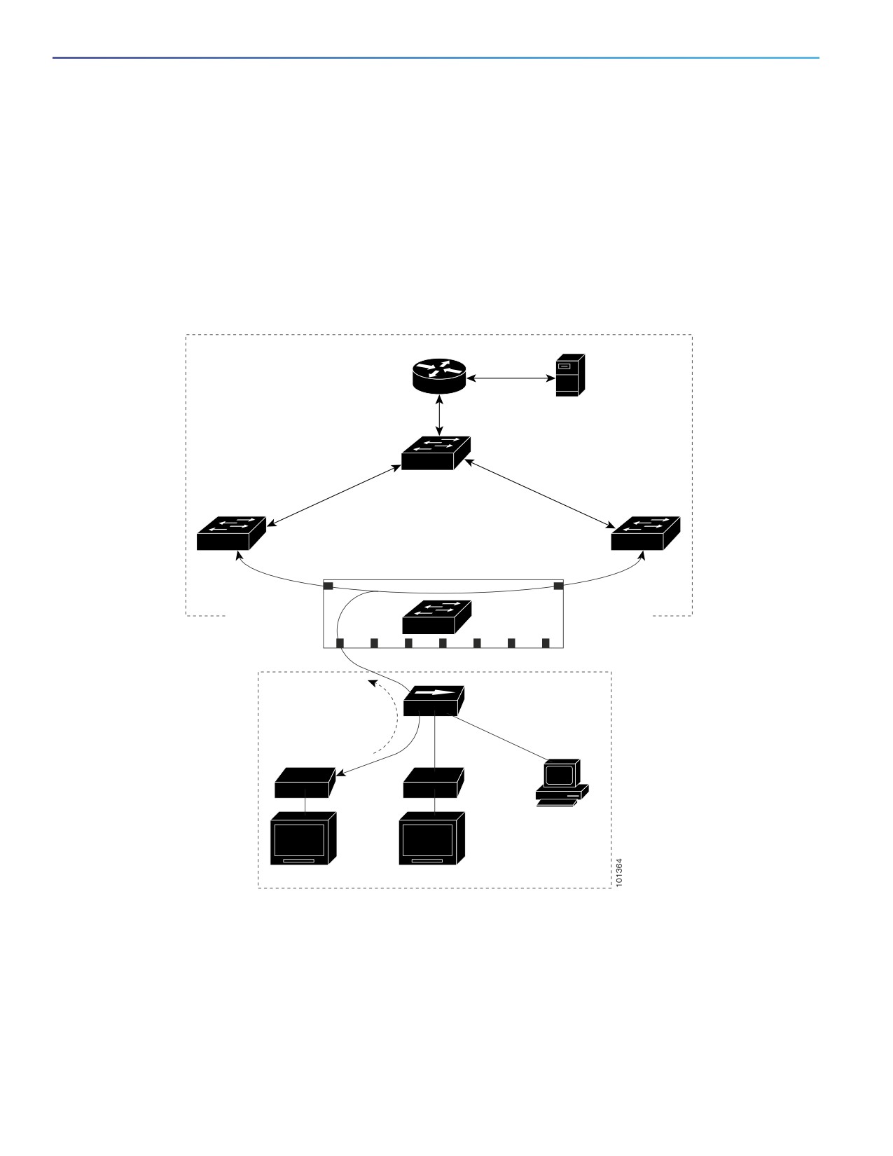
MVR in a Multicast Television Application
In a multicast television application, a PC or a television with a set-top box can receive the multicast stream. Multiple
set-top boxes or PCs can be connected to one subscriber port, which is a switch port configured as an MVR receiver
port. Figure 67 on page 456 is an example configuration. DHCP assigns an IP address to the set-top box or the PC. When
a subscriber selects a channel, the set-top box or PC sends an IGMP report to Switch A to join the appropriate multicast.
If the IGMP report matches one of the configured IP multicast group addresses, the switch CPU modifies the hardware
address table to include this receiver port and VLAN as a forwarding destination of the specified multicast stream when
it is received from the multicast VLAN. Uplink ports that send and receive multicast data to and from the multicast VLAN
are called MVR source ports.
Figure 67
Multicast VLAN Registration Example
Multicast VLAN
Cisco router
Multicast
server
SP
Switch B
SP
SP
SP
SP
SP
SP1
SP2
Multicast
Multicast
data
data
Switch A
RP1 RP2 RP3 RP4 RP5 RP6 RP7
Customer
premises
Hub
IGMP join
Set-top box
Set-top box
TV
data
PC
TV
TV
RP = Receiver Port
Note: All source ports belong to
SP = Source Port
the multicast VLAN.
When a subscriber changes channels or turns off the television, the set-top box sends an IGMP leave message for the
multicast stream. The switch CPU sends a MAC-based general query through the receiver port VLAN. If there is another
set-top box in the VLAN still subscribing to this group, that set-top box must respond within the maximum response time
specified in the query. If the CPU does not receive a response, it eliminates the receiver port as a forwarding destination
for this group.
456

Configuring IGMP Snooping and MVR
Information About IGMP Snooping and MVR
Without Immediate Leave, when the switch receives an IGMP leave message from a subscriber on a receiver port, it
sends out an IGMP query on that port and waits for IGMP group membership reports. If no reports are received in a
configured time period, the receiver port is removed from multicast group membership. With Immediate Leave, an IGMP
query is not sent from the receiver port on which the IGMP leave was received. As soon as the leave message is received,
the receiver port is removed from multicast group membership, which speeds up leave latency. Enable the Immediate
Leave feature only on receiver ports to which a single receiver device is connected.
MVR eliminates the need to duplicate television-channel multicast traffic for subscribers in each VLAN. Multicast traffic
for all channels is only sent around the VLAN trunk once—only on the multicast VLAN. The IGMP leave and join messages
are in the VLAN to which the subscriber port is assigned. These messages dynamically register for streams of multicast
traffic in the multicast VLAN on the Layer 3 device. Switch B. The access layer switch, Switch A, modifies the forwarding
behavior to allow the traffic to be forwarded from the multicast VLAN to the subscriber port in a different VLAN,
selectively allowing traffic to cross between two VLANs.
IGMP reports are sent to the same IP multicast group address as the multicast data. The Switch A CPU must capture all
IGMP join and leave messages from receiver ports and forward them to the multicast VLAN of the source (uplink) port,
based on the MVR mode.
Default MVR Settings
Feature
Default Setting
MVR
Disabled globally and per interface
Multicast addresses
None configured
Query response time
0.5 second
Multicast VLAN
VLAN 1
Mode
Compatible
Interface (per port) default
Neither a receiver nor a source port
Immediate Leave
Disabled on all ports
MVR Configuration Guidelines and Limitations
Receiver ports can only be access ports; they cannot be trunk ports. Receiver ports on a switch can be in different
VLANs, but should not belong to the multicast VLAN.
The maximum number of multicast entries (MVR group addresses) that can be configured on a switch (that is, the
maximum number of television channels that can be received) is 256.
MVR multicast data received in the source VLAN and leaving from receiver ports has its time-to-live (TTL)
decremented by 1 in the switch.
Because MVR on the switch uses IP multicast addresses instead of MAC multicast addresses, aliased IP multicast
addresses are allowed on the switch. However, if the switch is interoperating with Catalyst 3550 or Catalyst 3500
XL switches, you should not configure IP addresses that alias between themselves or with the reserved IP multicast
addresses (in the range 224.0.0.xxx).
Do not configure MVR on private VLAN ports.
MVR is not supported when multicast routing is enabled on a switch. If you enable multicast routing and a multicast
routing protocol while MVR is enabled, MVR is disabled, and you receive a warning message. If you try to enable
MVR while multicast routing and a multicast routing protocol are enabled, the operation to enable MVR is cancelled,
and you receive an error message.
MVR can coexist with IGMP snooping on a switch.
457

Configuring IGMP Snooping and MVR
Information About IGMP Snooping and MVR
MVR data received on an MVR receiver port is not forwarded to MVR source ports.
MVR does not support IGMPv3 messages.
IGMP Filtering and Throttling
In some environments, for example, metropolitan or multiple-dwelling unit (MDU) installations, you might want to control
the set of multicast groups to which a user on a switch port can belong. You can control the distribution of multicast
services, such as IP/TV, based on some type of subscription or service plan. You might also want to limit the number of
multicast groups to which a user on a switch port can belong.
With the IGMP filtering feature, you can filter multicast joins on a per-port basis by configuring IP multicast profiles and
associating them with individual switch ports. An IGMP profile can contain one or more multicast groups and specifies
whether access to the group is permitted or denied. If an IGMP profile denying access to a multicast group is applied to
a switch port, the IGMP join report requesting the stream of IP multicast traffic is dropped, and the port is not allowed to
receive IP multicast traffic from that group. If the filtering action permits access to the multicast group, the IGMP report
from the port is forwarded for normal processing. You can also set the maximum number of IGMP groups that a Layer 2
interface can join.
IGMP filtering controls only group-specific query and membership reports, including join and leave reports. It does not
control general IGMP queries. IGMP filtering has no relationship with the function that directs the forwarding of IP
multicast traffic. The filtering feature operates in the same manner whether CGMP or MVR is used to forward the multicast
traffic.
IGMP filtering is applicable only to the dynamic learning of IP multicast group addresses, not static configuration.
With the IGMP throttling feature, you can set the maximum number of IGMP groups that a Layer 2 interface can join. If
the maximum number of IGMP groups is set, the IGMP snooping forwarding table contains the maximum number of
entries, and the interface receives an IGMP join report, you can configure an interface to drop the IGMP report or to
replace the randomly selected multicast entry with the received IGMP report.
Note: IGMPv3 join and leave messages are not supported on switches running IGMP filtering.
Default IGMP Filtering and Throttling Configuration
Feature
Default Setting
IGMP filters
None applied
IGMP maximum number of IGMP groups
No maximum set
IGMP profiles
None defined
IGMP profile action
Deny the range addresses
When the maximum number of groups is in forwarding table, the default IGMP throttling action is to deny the IGMP report.
IGMP Profiles
To configure an IGMP profile, use the ip igmp profile global configuration command with a profile number to create an
IGMP profile and to enter IGMP profile configuration mode. From this mode, you can specify the parameters of the IGMP
profile to be used for filtering IGMP join requests from a port. When you are in IGMP profile configuration mode, you can
create the profile by using these commands:
deny—Specifies that matching addresses are denied; this is the default.
exit—Exits from igmp-profile configuration mode.
no—Negates a command or returns to its defaults.
458
Configuring IGMP Snooping and MVR
How to Configure IGMP Snooping and MVR
permit—Specifies that matching addresses are permitted.
range—Specifies a range of IP addresses for the profile. You can enter a single IP address or a range with a start and
an end address.
The default is for the switch to have no IGMP profiles configured. When a profile is configured, if neither the permit nor
deny keyword is included, the default is to deny access to the range of IP addresses.
To control access as defined in an IGMP profile, use the ip igmp filter interface configuration command to apply the
profile to the appropriate interfaces. You can apply IGMP profiles only to Layer 2 access ports; you cannot apply IGMP
profiles to routed ports or SVIs. You cannot apply profiles to ports that belong to an EtherChannel port group. You can
apply a profile to multiple interfaces, but each interface can have only one profile applied to it.
IGMP Throttling Action
After you set the maximum number of IGMP groups that a Layer 2 interface can join, you can configure an interface to
replace the existing group with the new group for which the IGMP report was received by using the ip igmp max-groups
action replace interface configuration command. Use the no form of this command to return to the default, which is to
drop the IGMP join report.
Follow these guidelines when configuring the IGMP throttling action:
This restriction can be applied only to Layer 2 ports. You can use this command on a logical EtherChannel interface
but cannot use it on ports that belong to an EtherChannel port group.
When the maximum group limitation is set to the default (no maximum), entering the ip igmp max-groups action
{deny | replace} command has no effect.
If you configure the throttling action and set the maximum group limitation after an interface has added multicast
entries to the forwarding table, the forwarding-table entries are either aged out or removed, depending on the
throttling action.
— If you configure the throttling action as deny, the entries that were previously in the forwarding table are not
removed but are aged out. After these entries are aged out and the maximum number of entries is in the
forwarding table, the switch drops the next IGMP report received on the interface.
— If you configure the throttling action as replace, the entries that were previously in the forwarding table are
removed. When the maximum number of entries is in the forwarding table, the switch replaces a randomly
selected entry with the received IGMP report.
To prevent the switch from removing the forwarding-table entries, you can configure the IGMP throttling action
before an interface adds entries to the forwarding table.
How to Configure IGMP Snooping and MVR
Configuring IGMP Snooping
Enabling or Disabling IGMP Snooping
By default, IGMP snooping is globally enabled on the switch. When globally enabled or disabled, it is also enabled or
disabled in all existing VLAN interfaces. IGMP snooping is by default enabled on all VLANs, but can be enabled and
disabled on a per-VLAN basis.
459

Configuring IGMP Snooping and MVR
How to Configure IGMP Snooping and MVR
Command
Purpose
1.
configure terminal
Enters global configuration mode.
2.
ip igmp snooping
Globally enables IGMP snooping in all existing VLAN interfaces.
or
or
ip igmp snooping vlan vlan-id
Enables IGMP snooping on the VLAN interface. The VLAN ID range is 1 to
1001 and 1006 to 4096.
IGMP snooping must be globally enabled before you can enable VLAN
snooping.
3.
end
Returns to privileged EXEC mode.
Setting IGMP Snooping Parameters
Command
Purpose
1.
configure terminal
Enters global configuration mode.
2.
ip igmp snooping vlan vlan-id mrouter
(Optional) Enables IGMP snooping on a VLAN. The VLAN ID range is 1
learn {cgmp | pim-dvmrp}
to 1001 and 1006 to 4096.
Specifies the multicast router learning method:
cgmp—Listens for CGMP packets. This method is useful for
reducing control traffic.
pim-dvmrp—Snoops on IGMP queries and PIM-DVMRP packets.
This is the default.
3.
ip igmp snooping vlan vlan-id mrouter
Adds a multicast router port (adds a static connection to a multicast
interface interface-id
router).
(Optional) Specifies the multicast router VLAN ID and the interface to
the multicast router.
The VLAN ID range is 1 to 1001 and 1006 to 4096.
The interface can be a physical interface or a port channel. The
port-channel range is 1 to 10.
Static connections to multicast routers are supported only on
switch ports.
4.
ip igmp snooping vlan vlan-id static
(Optional) Statically configures a Layer 2 port as a member of a
ip_address interface interface-id
multicast group:
vlan-id—Multicast group VLAN ID. The range is 1 to 1001 and
1006 to 4096.
ip-address—Group IP address.
interface-id—Member port. It can be a physical interface or a port
channel (1 to 6).
5.
ip igmp snooping vlan vlan-id
(Optional) Enables IGMP Immediate Leave on the VLAN interface.
immediate-leave
Note: Immediate Leave is supported only on IGMP Version 2 hosts.
460

Configuring IGMP Snooping and MVR
How to Configure IGMP Snooping and MVR
Command
Purpose
6.
ip igmp snooping
(Optional) Configures the IGMP leave timer globally. The range is 100
last-member-query-interval time
to 32768 milliseconds. The default is 1000 seconds.
7.
ip igmp snooping vlan vlan-id
(Optional) Configures the IGMP leave time on the VLAN interface. The
last-member-query-interval time
range is 100 to 32768 milliseconds.
Note: Configuring the leave time on a VLAN overrides the globally
configured timer.
8.
end
Returns to privileged EXEC mode.
Configuring TCN
Command
Purpose
1.
configure terminal
Enters global configuration mode.
2.
ip igmp snooping tcn flood query count
Specifies the number of IGMP general queries for which the multicast
count
traffic is flooded. The range is 1 to 10. By default, the flooding query
count is 2.
3.
ip igmp snooping tcn query solicit
Sends an IGMP leave message (global leave) to speed the process
of recovering from the flood mode caused during a TCN event. By
default, query solicitation is disabled.
Note: Enable the switch to send the global leave message whether
or not it is the spanning-tree root.
4.
interface interface-id
Specifies the interface to be configured, and enter interface
configuration mode.
5.
no ip igmp snooping tcn flood
Disables the flooding of multicast traffic during a spanning-tree TCN
event.
By default, multicast flooding is enabled on an interface.
6.
end
Returns to privileged EXEC mode.
Configuring the IGMP Snooping Querier
Command
Purpose
1.
configure terminal
Enters global configuration mode.
2.
ip igmp snooping querier
Enables the IGMP snooping querier.
3.
ip igmp snooping querier address
(Optional) Specifies an IP address for the IGMP snooping querier. If
ip_address
you do not specify an IP address, the querier tries to use the global
IP address configured for the IGMP querier.
Note: The IGMP snooping querier does not generate an IGMP
general query if it cannot find an IP address on the switch.
4.
ip igmp snooping querier query-interval
(Optional) Sets the interval between IGMP queriers. The range is 1 to
interval-count
18000 seconds.
5.
ip igmp snooping querier tcn query [count
(Optional) Sets the time between Topology Change Notification
count | interval interval]
(TCN) queries. The count range is 1 to 10. The interval range is 1 to
255 seconds.
461

Configuring IGMP Snooping and MVR
How to Configure IGMP Snooping and MVR
Command
Purpose
6.
ip igmp snooping querier timer expiry
(Optional) Sets the length of time until the IGMP querier expires. The
timeout
range is 60 to 300 seconds.
7.
ip igmp snooping querier version version
(Optional) Selects the IGMP version number that the querier feature
uses. Select 1 or 2.
8.
end
Returns to privileged EXEC mode.
Disabling IGMP Report Suppression
Before You Begin
IGMP report suppression is supported only when the multicast query has IGMPv1 and IGMPv2 reports. This feature is not
supported when the query includes IGMPv3 reports.
Command
Purpose
1.
configure terminal
Enters global configuration mode.
2.
no ip igmp snooping report-suppression
Disables IGMP report suppression.
3.
end
Returns to privileged EXEC mode.
Configuring MVR
Configuring MVR Global Parameters
You do not need to set the optional MVR parameters if you choose to use the default settings. If you do want to change
the default parameters (except for the MVR VLAN), you must first enable MVR.
Command
Purpose
1.
configure terminal
Enters global configuration mode.
2.
mvr
Enables MVR on the switch.
3.
mvr group ip-address [count]
Configures an IP multicast address on the switch or use the count parameter
to configure a contiguous series of MVR group addresses (the range for count
is 1 to 256; the default is 1). Any multicast data sent to this address is sent to
all source ports on the switch and all receiver ports that have elected to
receive data on that multicast address. Each multicast address would
correspond to one television channel.
4.
mvr querytime value
(Optional) Defines the maximum time to wait for IGMP report memberships
on a receiver port before removing the port from multicast group
membership. The value is in units of tenths of a second. The range is 1 to 100,
and the default is 5 tenths or one-half second.
462

Configuring IGMP Snooping and MVR
How to Configure IGMP Snooping and MVR
Command
Purpose
5.
mvr vlan vlan-id
(Optional) Specifies the VLAN in which multicast data is received; all source
ports must belong to this VLAN. The VLAN range is 1 to 1001 and 1006 to
4096. The default is VLAN 1.
6.
mvr mode {dynamic | compatible}
(Optional) Specifies the MVR mode of operation:
dynamic—Allows dynamic MVR membership on source ports.
compatible—Is compatible with Catalyst 3500 XL and Catalyst 2900 XL
switches and does not support IGMP dynamic joins on source ports.
The default is compatible mode.
7.
end
Returns to privileged EXEC mode.
Configuring MVR Interfaces
Command
Purpose
1.
configure terminal
Enters global configuration mode.
2.
mvr
Enables MVR on the switch.
3.
interface interface-id
Specifies the Layer 2 port to configure, and enters interface configuration
mode.
4.
mvr type {source | receiver}
Configures an MVR port as one of these:
source—Configures uplink ports that receive and send multicast data as
source ports. Subscribers cannot be directly connected to source ports.
All source ports on a switch belong to the single multicast VLAN.
receiver—Configures a port as a receiver port if it is a subscriber port
and should only receive multicast data. It does not receive data unless
it becomes a member of the multicast group, either statically or by using
IGMP leave and join messages. Receiver ports cannot belong to the
multicast VLAN.
The default configuration is as a non-MVR port. If you attempt to configure
a non-MVR port with MVR characteristics, the operation fails.
5.
mvr vlan vlan-id group [ip-address]
(Optional) Statically configures a port to receive multicast traffic sent to the
multicast VLAN and the IP multicast address. A port statically configured as
a member of a group remains a member of the group until statically
removed.
Note: In compatible mode, this command applies to only receiver ports. In
dynamic mode, it applies to receiver ports and source ports.
Receiver ports can also dynamically join multicast groups by using IGMP join
and leave messages.
6.
mvr immediate
(Optional) Enables the Immediate-Leave feature of MVR on the port.
Note: This command applies to only receiver ports and should only be
enabled on receiver ports to which a single receiver device is connected.
7.
end
Returns to privileged EXEC mode.
463

Configuring IGMP Snooping and MVR
How to Configure IGMP Snooping and MVR
Configuring IGMP
Configuring IGMP Profiles
Command
Purpose
1.
configure terminal
Enters global configuration mode.
2.
ip igmp profile profile number
Assigns a number to the profile you are configuring, and enter IGMP
profile configuration mode. The profile number range is 1 to
4294967295.
3.
permit | deny
(Optional) Sets the action to permit or deny access to the IP multicast
address. If no action is configured, the default for the profile is to deny
access.
4.
range ip multicast address
Enters the IP multicast address or range of IP multicast addresses to
which access is being controlled. If entering a range, enter the low IP
multicast address, a space, and the high IP multicast address.
You can use the range command multiple times to enter multiple
addresses or ranges of addresses.
5.
end
Returns to privileged EXEC mode.
Configuring IGMP Interfaces
Command
Purpose
1.
configure terminal
Enters global configuration mode.
2.
interface interface-id
Specifies the physical interface, and enter interface configuration mode.
The interface must be a Layer 2 port that does not belong to an
EtherChannel port group.
3.
ip igmp filter profile number
Applies the specified IGMP profile to the interface. The range is 1 to
4294967295.
4.
ip igmp max-groups number
Sets the maximum number of IGMP groups that the interface can join.
The range is 0 to 4294967294. The default is to have no maximum set.
5.
ip igmp max-groups action {deny |
When an interface receives an IGMP report and the maximum number
replace}
of entries is in the forwarding table, specify the action that the interface
takes:
deny—Drops the report.
replace—Replaces the existing group with the new group for which
the IGMP report was received.
6.
end
Returns to privileged EXEC mode.
464

Configuring IGMP Snooping and MVR
Monitoring and Maintaining IGMP Snooping and MVR
Monitoring and Maintaining IGMP Snooping and MVR
Command
Purpose
show ip igmp snooping [vlan vlan-id]
Displays the snooping configuration information for all VLANs on the
switch or for a specified VLAN.
(Optional) Enter vlan vlan-id to display information for a single VLAN. The
VLAN ID range is 1 to 1001 and 1006 to 4096.
show ip igmp snooping groups [count |dynamic
Displays multicast table information for the switch or about a specific
[count] | user [count]]
parameter:
count—Displays the total number of entries for the specified
command options instead of the actual entries.
dynamic—Displays entries learned through IGMP snooping.
user—Displays only the user-configured multicast entries.
show ip igmp snooping groups vlan vlan-id
Displays multicast table information for a multicast VLAN or about a
[ip_address | count | dynamic [count] |
specific parameter for the VLAN:
user[count]]
vlan-id—The VLAN ID range is 1 to 1001 and 1006 to 4096.
count—Displays the total number of entries for the specified
command options instead of the actual entries.
dynamic—Displays entries learned through IGMP snooping.
ip_address—Displays characteristics of the multicast group with the
specified group IP address.
user—Displays only the user-configured multicast entries.
show ip igmp snooping mrouter [vlan vlan-id]
Displays information on dynamically learned and manually configured
multicast router interfaces.
Note: When you enable IGMP snooping, the switch automatically learns
the interface to which a multicast router is connected. These are
dynamically learned interfaces.
(Optional) Enter vlan vlan-id to display information for a single VLAN.
show ip igmp snooping querier [vlan vlan-id]
Displays information about the IP address and receiving port for the
most-recently received IGMP query messages in the VLAN.
(Optional) Enter vlan vlan-id to display information for a single VLAN.
show ip igmp snooping querier [vlan vlan-id]
Displays information about the IP address and receiving port of the
detail
most-recently received IGMP query message in the VLAN and the
configuration and operational state of the IGMP snooping querier in the
VLAN.
show ip igmp profile [profile number]
Displays the specified IGMP profile or all the IGMP profiles defined on the
switch.
show mvr
Displays MVR status and values for the switch—whether MVR is enabled
or disabled, the multicast VLAN, the maximum (256) and current (0
through 256) number of multicast groups, the query response time, and
the MVR mode.
465

Configuring IGMP Snooping and MVR
Configuration Examples for IGMP Snooping
Command
Purpose
show mvr interface [interface-id] [members
Displays all MVR interfaces and their MVR configurations.
[vlan vlan-id]]
When a specific interface is entered, displays this information:
Type—Receiver or Source
Status—One of these:
— Active means the port is part of a VLAN.
— Up/Down means that the port is forwarding or nonforwarding.
— Inactive means that the port is not part of any VLAN.
Immediate Leave—Enabled or Disabled
If the members keyword is entered, displays all multicast group
members on this port or, if a VLAN identification is entered, all multicast
group members on the VLAN. The VLAN ID range is 1 to 1001 and 1006
to 4096.
show mvr members [ip-address]
Displays all receiver and source ports that are members of any IP
multicast group or the specified IP multicast group IP address.
show ip igmp profile profile number
Verifies the profile configuration.
show ip igmp snooping mrouter [vlan vlan-id]
Verifies that IGMP snooping is enabled on the VLAN interface.
Configuration Examples for IGMP Snooping
Configuring IGMP Snooping: Example
This example shows how to configure IGMP snooping to use CGMP packets as the learning method:
Switch# configure terminal
Switch(config)# ip igmp snooping vlan 1 mrouter learn cgmp
Switch(config)# end
Disabling a Multicast Router Port: Example
To remove a multicast router port from the VLAN, use the no ip igmp snooping vlan vlan-id mrouter interface
interface-id global configuration command.
This example shows how to enable a static connection to a multicast router:
Switch# configure terminal
Switch(config)# ip igmp snooping vlan 200 mrouter interface GigabitEthernet1/18
Switch(config)# end
Statically Configuring a Host on a Port: Example
This example shows how to statically configure a host on a port:
Switch# configure terminal
Switch(config)# ip igmp snooping vlan 105 static 224.2.4.12 interface gigabitethernet1/1
Switch(config)# end
466
Configuring IGMP Snooping and MVR
Configuration Examples for IGMP Snooping
Enabling IGMP Immediate Leave: Example
This example shows how to enable IGMP Immediate Leave on VLAN 130:
Switch# configure terminal
Switch(config)# ip igmp snooping vlan 130 immediate-leave
Switch(config)# end
Setting the IGMP Snoopng Querier Parameters: Examples
This example shows how to set the IGMP snooping querier source address to 10.0.0.64:
Switch# configure terminal
Switch(config)# ip igmp snooping querier 10.0.0.64
Switch(config)# end
This example shows how to set the IGMP snooping querier maximum response time to 25 seconds:
Switch# configure terminal
Switch(config)# ip igmp snooping querier query-interval 25
Switch(config)# end
This example shows how to set the IGMP snooping querier timeout to 60 seconds:
Switch# configure terminal
Switch(config)# ip igmp snooping querier timeout expiry 60
Switch(config)# end
This example shows how to set the IGMP snooping querier feature to version 2:
Switch# configure terminal
Switch(config)# no ip igmp snooping querier version 2
Switch(config)# end
Enabling MVR: Examples
This example shows how to enable MVR, configure the group address, set the query time to 1 second (10 tenths), specify
the MVR multicast VLAN as VLAN 22, and set the MVR mode as dynamic:
Switch(config)# mvr
Switch(config)# mvr group 228.1.23.4
Switch(config)# mvr querytime 10
Switch(config)# mvr vlan 22
Switch(config)# mvr mode dynamic
Switch(config)# end
You can use the show mvr members privileged EXEC command to verify the MVR multicast group addresses on the
switch.
This example shows how to configure a port as a receiver port, statically configure the port to receive multicast traffic
sent to the multicast group address, configure Immediate Leave on the port, and verify the results:
Switch(config)# mvr
Switch(config)# interface GigabitEthernet1/18
Switch(config-if)# mvr type receiver
Switch(config-if)# mvr vlan 22 group 228.1.23.4
Switch(config-if)# mvr immediate
Switch(config)# end
Switch# show mvr interface
Port
Type
Status
Immediate Leave
467
Configuring IGMP Snooping and MVR
Additional References
----
----
-------
---------------
Gi1/18
RECEIVER
ACTIVE/DOWN
ENABLED
Creating an IGMP Profile: Example
This example shows how to create IGMP profile 4 allowing access to the single IP multicast address and how to verify
the configuration. If the action was to deny (the default), it would not appear in the show ip igmp profile output display.
Switch(config)# ip igmp profile 4
Switch(config-igmp-profile)# permit
Switch(config-igmp-profile)# range 229.9.9.0
Switch(config-igmp-profile)# end
Switch# show ip igmp profile 4
IGMP Profile 4
permit
range 229.9.9.0 229.9.9.0
Applying an IGMP Profile: Example
This example shows how to apply IGMP profile 4 to a port:
Switch(config)# interface GigabitEthernet1/18
Switch(config-if)# ip igmp filter 4
Switch(config-if)# end
Limiting IGMP Groups: Example
This example shows how to limit to 25 the number of IGMP groups that a port can join:
Switch(config)# interface GigabitEthernet1/18
Switch(config-if)# ip igmp max-groups 25
Switch(config-if)# end
Additional References
The following sections provide references related to switch administration:
468

Configuring IGMP Snooping and MVR
Additional References
Related Documents
Related Topic
Document Title
Cisco IOS basic commands
Cisco IOS Configuration Fundamentals Command Reference
Cisco IOS multicast commands
Cisco IOS IP Command Reference, Volume 3 of 3:Multicast
Standards
Standards
Title
No new or modified standards are supported by this
—
feature, and support for existing standards has not
been modified by this feature.
MIBs
MIBs
MIBs Link
—
To locate and download MIBs using Cisco IOS XR software, use the
Cisco MIB Locator found at the following URL and choose a platform
under the Cisco Access Products menu:
RFCs
RFCs
Title
No new or modified RFCs are supported by this
—
feature, and support for existing RFCs has not been
modified by this feature.
Technical Assistance
Description
Link
The Cisco Technical Support website contains
thousands of pages of searchable technical content,
including links to products, technologies, solutions,
technical tips, and tools. Registered Cisco.com users
can log in from this page to access even more content.
469
Configuring IGMP Snooping and MVR
Additional References
470
Configuring Port-Based Traffic Control
Restrictions for Port-Based Traffic Control
To use this feature, the switch must be running the LAN Base image.
Information About Port-Based Traffic Control
Storm Control
Storm control prevents traffic on a LAN from being disrupted by a broadcast, multicast, or unicast storm on one of the
physical interfaces. A LAN storm occurs when packets flood the LAN, creating excessive traffic and degrading network
performance. Errors in the protocol-stack implementation, mistakes in network configurations, or users issuing a
denial-of-service attack can cause a storm.
Storm control (or traffic suppression) monitors packets passing from an interface to the switching bus and determines if
the packet is unicast, multicast, or broadcast. The switch counts the number of packets of a specified type received
within the 1-second time interval and compares the measurement with a predefined suppression-level threshold.
Storm control uses one of these methods to measure traffic activity:
Bandwidth as a percentage of the total available bandwidth of the port that can be used by the broadcast, multicast,
or unicast traffic
Traffic rate in packets per second at which broadcast, multicast, or unicast packets are received.
Traffic rate in bits per second at which broadcast, multicast, or unicast packets are received.
Traffic rate in packets per second and for small frames. This feature is enabled globally. The threshold for small
frames is configured for each interface.
With each method, the port blocks traffic when the rising threshold is reached. The port remains blocked until the traffic
rate drops below the falling threshold (if one is specified) and then resumes normal forwarding. If the falling suppression
level is not specified, the switch blocks all traffic until the traffic rate drops below the rising suppression level. In general,
the higher the level, the less effective the protection against broadcast storms.
Note: When the storm control threshold for multicast traffic is reached, all multicast traffic except control traffic, such as
bridge protocol data unit (BDPU) and Cisco Discovery Protocol (CDP) frames, are blocked. However, the switch does not
differentiate between routing updates, such as OSPF, and regular multicast data traffic, so both types of traffic are
blocked.
The graph in Figure 68 on page 472 shows broadcast traffic patterns on an interface over a given period of time. The
example can also be applied to multicast and unicast traffic. In this example, the broadcast traffic being forwarded
exceeded the configured threshold between time intervals T1 and T2 and between T4 and T5. When the amount of
specified traffic exceeds the threshold, all traffic of that kind is dropped for the next time period. Therefore, broadcast
traffic is blocked during the intervals following T2 and T5. At the next time interval (for example, T3), if broadcast traffic
does not exceed the threshold, it is again forwarded.
471

Configuring Port-Based Traffic Control
Information About Port-Based Traffic Control
Figure 68
Broadcast Storm Control Example
Forwarded traffic
Blocked traffic
Total
number of
Threshold
broadcast
packets
or bytes
0
T1
T2
T3
T4
T5
Time
The combination of the storm-control suppression level and the 1-second time interval controls the way the storm control
algorithm works. A higher threshold allows more packets to pass through. A threshold value of 100 percent means that
no limit is placed on the traffic. A value of 0.0 means that all broadcast, multicast, or unicast traffic on that port is blocked.
Note: Because packets do not arrive at uniform intervals, the 1-second time interval during which traffic activity is
measured can affect the behavior of storm control.
You use the storm-control interface configuration commands to set the threshold value for each traffic type.
Default Storm Control Configuration
By default, unicast, broadcast, and multicast storm control are disabled on the switch interfaces; that is, the suppression
level is 100 percent.
Storm Control and Threshold Levels
You configure storm control on a port and enter the threshold level that you want to be used for a particular type of traffic.
However, because of hardware limitations and the way in which packets of different sizes are counted, threshold
percentages are approximations. Depending on the sizes of the packets making up the incoming traffic, the actual
enforced threshold might differ from the configured level by several percentage points.
Note: Storm control is supported on physical interfaces. You can also configure storm control on an EtherChannel. When
storm control is configured on an EtherChannel, the storm control settings propagate to the EtherChannel physical
interfaces.
Small-Frame Arrival Rate
Incoming VLAN-tagged packets smaller than 67 bytes are considered small frames. They are forwarded by the switch,
but they do not cause the switch storm-control counters to increment. In Cisco IOS Release 12.2(44)SE and later, you
can configure a port to be error disabled if small frames arrive at a specified rate (threshold).
You globally enable the small-frame arrival feature on the switch and then configure the small-frame threshold for
packets on each interface. Packets smaller than the minimum size and arriving at a specified rate (the threshold) are
dropped since the port is error disabled.
If the errdisable recovery cause small-frame global configuration command is entered, the port is reenabled after a
specified time. (You specify the recovery time by using errdisable recovery global configuration command.)
472
Configuring Port-Based Traffic Control
Information About Port-Based Traffic Control
Protected Ports
Some applications require that no traffic be forwarded at Layer 2 between ports on the same switch so that one neighbor
does not see the traffic generated by another neighbor. In such an environment, the use of protected ports ensures that
there is no exchange of unicast, broadcast, or multicast traffic between these ports on the switch.
Protected ports have these features:
A protected port does not forward any traffic (unicast, multicast, or broadcast) to any other port that is also a
protected port. Data traffic cannot be forwarded between protected ports at Layer 2; only control traffic, such as PIM
packets, is forwarded because these packets are processed by the CPU and forwarded in software. All data traffic
passing between protected ports must be forwarded through a Layer 3 device.
Forwarding behavior between a protected port and a nonprotected port proceeds as usual.
Protected Port Configuration Guidelines
You can configure protected ports on a physical interface (for example, Gigabit Ethernet port 1) or an EtherChannel group
(for example, port-channel 5). When you enable protected ports for a port channel, it is enabled for all ports in the
port-channel group.
Do not configure a private-VLAN port as a protected port. Do not configure a protected port as a private-VLAN port. A
private-VLAN isolated port does not forward traffic to other isolated ports or community ports.
Port Blocking
By default, the switch floods packets with unknown destination MAC addresses out of all ports. If unknown unicast and
multicast traffic is forwarded to a protected port, there could be security issues. To prevent unknown unicast or multicast
traffic from being forwarded from one port to another, you can block a port (protected or nonprotected) from flooding
unknown unicast or multicast packets to other ports.
Note: With multicast traffic, the port blocking feature blocks only pure Layer 2 packets. Multicast packets that contain
IPv4 or IPv6 information in the header are not blocked.
Port Security
You can use the port security feature to restrict input to an interface by limiting and identifying MAC addresses of the
stations allowed to access the port. When you assign secure MAC addresses to a secure port, the port does not forward
packets with source addresses outside the group of defined addresses. If you limit the number of secure MAC addresses
to one and assign a single secure MAC address, the workstation attached to that port is assured the full bandwidth of
the port.
If a port is configured as a secure port and the maximum number of secure MAC addresses is reached, when the MAC
address of a station attempting to access the port is different from any of the identified secure MAC addresses, a security
violation occurs. Also, if a station with a secure MAC address configured or learned on one secure port attempts to
access another secure port, a violation is flagged.
Secure MAC Addresses
You configure the maximum number of secure addresses allowed on a port by using the switchport port-security
maximum value interface configuration command.
Note: If you try to set the maximum value to a number less than the number of secure addresses already configured on
an interface, the command is rejected.
The switch supports these types of secure MAC addresses:
473
Configuring Port-Based Traffic Control
Information About Port-Based Traffic Control
Static secure MAC addresses—These are manually configured by using the switchport port-security mac-address
mac-address interface configuration command, stored in the address table, and added to the switch running
configuration.
Dynamic secure MAC addresses—These are dynamically configured, stored only in the address table, and removed
when the switch restarts.
Sticky secure MAC addresses—These can be dynamically learned or manually configured, stored in the address
table, and added to the running configuration. If these addresses are saved in the configuration file, when the switch
restarts, the interface does not need to dynamically reconfigure them.
You can configure an interface to convert the dynamic MAC addresses to sticky secure MAC addresses and to add them
to the running configuration by enabling sticky learning. To enable sticky learning, enter the switchport port-security
mac-address sticky interface configuration command. When you enter this command, the interface converts all the
dynamic secure MAC addresses, including those that were dynamically learned before sticky learning was enabled, to
sticky secure MAC addresses. All sticky secure MAC addresses are added to the running configuration.
The sticky secure MAC addresses do not automatically become part of the configuration file, which is the startup
configuration used each time the switch restarts. If you save the sticky secure MAC addresses in the configuration file,
when the switch restarts, the interface does not need to relearn these addresses. If you do not save the sticky secure
addresses, they are lost.
If sticky learning is disabled, the sticky secure MAC addresses are converted to dynamic secure addresses and are
removed from the running configuration.
The maximum number of secure MAC addresses that you can configure on a switch is set by the maximum number of
available MAC addresses allowed in the system. This number is determined by the active Switch Database Management
(SDM) template. This number is the total of available MAC addresses, including those used for other Layer 2 functions
and any other secure MAC addresses configured on interfaces.
Security Violations
It is a security violation when one of these situations occurs:
The maximum number of secure MAC addresses have been added to the address table, and a station whose MAC
address is not in the address table attempts to access the interface.
An address learned or configured on one secure interface is seen on another secure interface in the same VLAN and
on the same switch.
You can configure the interface for one of five violation modes, based on the action to be taken if a violation occurs:
protect—When the number of secure MAC addresses reaches the maximum limit allowed on the port, packets with
unknown source addresses are dropped until you remove a sufficient number of secure MAC addresses to drop
below the maximum value or increase the number of maximum allowable addresses. You are not notified that a
security violation has occurred.
We do not recommend configuring the protect violation mode on a trunk port. The protect mode disables learning
when any VLAN reaches its maximum limit, even if the port has not reached its maximum limit.
restrict—When the number of secure MAC addresses reaches the maximum limit allowed on the port, packets with
unknown source addresses are dropped until you remove a sufficient number of secure MAC addresses to drop
below the maximum value or increase the number of maximum allowable addresses. In this mode, you are notified
that a security violation has occurred. An SNMP trap is sent, a syslog message is logged, and the violation counter
increments.
shutdown—A port security violation causes the interface to become error-disabled and to shut down immediately,
and the port LED turns off. An SNMP trap is sent, a syslog message is logged, and the violation counter increments.
When a secure port is in the error-disabled state, you can bring it out of this state by entering the errdisable
recovery cause psecure-violation global configuration command, or you can manually reenable it by entering the
shutdown and no shut down interface configuration commands. This is the default mode.
474

Configuring Port-Based Traffic Control
Information About Port-Based Traffic Control
shutdown vlan—Use to set the security violation mode per-VLAN. In this mode, the VLAN is error disabled instead of
the entire port when a violation occurs.
report—This mode is similar to the restrict option, except that when the number of secure MAC addresses reaches
the maximum limit allowed on the port, packets with unknown source addresses are not dropped. Packets from an
unknown source are allowed, but you are notified that a security violation has occurred. A syslog message is logged
with the unknown MAC address, and the violation counter also increments.
Note: If you use report mode, do not configure the switchport port-security global command on the ingress
interface.
To switch between the report violation mode and another mode, you must explicitly disable all port-security
commands of the previous mode using the corresponding no command before adding the new configuration.
Table 48
Security Violation Mode Actions
Violation Mode
Traffic is
Sends SNMP
Sends syslog
Displays Error
Violation
Shuts Down
Forwarded1
Trap
Message
Message2
Counter
Port
Increments
protect
No
No
No
No
No
No
restrict
No
Yes
Yes
No
Yes
No
shutdown
No
No
No
No
Yes
Yes
shutdown vlan
No
No
Yes
No
Yes
No3
report
Yes
No
Yes
Yes
Yes
No
1. Packets with unknown source addresses are dropped until you remove a sufficient number of secure MAC addresses.
2. The switch returns an error message if you manually configure an address that would cause a security violation.
3. Shuts down only the VLAN on which the violation occurred.
Default Port Security Configuration
Feature
Default Setting
Port security
Disabled on a port.
Sticky address learning
Disabled.
Maximum number of secure MAC
1
addresses per port
Violation mode
Shutdown. The port shuts down when the maximum number of secure MAC
addresses is exceeded.
Port security aging
Disabled. Aging time is 0.
Static aging is disabled.
Type is absolute.
Port Security Configuration Guidelines
Port security can only be configured on static access ports or trunk ports. A secure port cannot be a dynamic access
port.
A secure port cannot be a destination port for Switched Port Analyzer (SPAN).
475
Configuring Port-Based Traffic Control
Information About Port-Based Traffic Control
A secure port cannot belong to a Fast EtherChannel port group.
Voice VLAN is only supported on access ports and not on trunk ports, even though the configuration is allowed.
When you enable port security on an interface that is also configured with a voice VLAN, set the maximum allowed
secure addresses on the port to two. When the port is connected to a Cisco IP phone, the IP phone requires one
MAC address. The Cisco IP phone address is learned on the voice VLAN, but is not learned on the access VLAN. If
you connect a single PC to the Cisco IP phone, no additional MAC addresses are required. If you connect more than
one PC to the Cisco IP phone, you must configure enough secure addresses to allow one for each PC and one for
the phone.
When a trunk port configured with port security and assigned to an access VLAN for data traffic and to a voice VLAN
for voice traffic, entering the switchport voice and switchport priority extend interface configuration commands
has no effect.
When a connected device uses the same MAC address to request an IP address for the access VLAN and then an
IP address for the voice VLAN, only the access VLAN is assigned an IP address.
When configuring port security, first specify the total number of MAC addresses you want to allow, by using the
switchport port-security maximum interface configuration command and then configure the number of access
VLANs (switchport port-security vlan access interface configuration command) and voice VLANs (switchport
port-security vlan voice interface configuration command) you want to allow. If you do not specify the total number
first, the system returns to the default setting (1 MAC address).
When you enter a maximum secure address value for an interface, and the new value is greater than the previous
value, the new value overwrites the previously configured value. If the new value is less than the previous value and
the number of configured secure addresses on the interface exceeds the new value, the command is rejected.
The switch does not support port security aging of sticky secure MAC addresses.
476

Configuring Port-Based Traffic Control
Information About Port-Based Traffic Control
Type of Port or Feature on Port
Compatible with Port Security
DTP1 port2
No
Trunk port
Yes
Dynamic-access port3
No
Routed port
No
SPAN source port
Yes
SPAN destination port
No
EtherChannel
No
Tunneling port
Yes
Protected port
Yes
IEEE 802.1x port
Yes
Voice VLAN port4
Yes
Private VLAN port
Yes
IP source guard
Yes
Dynamic Address Resolution Protocol (ARP) inspection
Yes
FlexLinks
Yes
1. DTP = Dynamic Trunking Protocol
2. A port configured with the switchport mode dynamic interface configuration command.
3. A VLAN Query Protocol (VQP) port configured with the switchport access vlan dynamic interface configuration
command.
4. You must set the maximum allowed secure addresses on the port to two plus the maximum number of secure
addresses allowed on the access VLAN.
Port Security Aging
You can use port security aging to set the aging time for all secure addresses on a port. Two types of aging are supported
per port:
Absolute—The secure addresses on the port are deleted after the specified aging time.
Inactivity—The secure addresses on the port are deleted only if the secure addresses are inactive for the specified
aging time.
Use this feature to remove and add devices on a secure port without manually deleting the existing secure MAC
addresses and to still limit the number of secure addresses on a port. You can enable or disable the aging of secure
addresses on a per-port basis.
Port Security and Private VLANs
Ports that have both port security and private VLANs (PVLANs) configured can be labeled secure PVLAN ports. When a
secure address is learned on a secure PVLAN port, the same secure address cannot be learned on another secure
PVLAN port belonging to the same primary VLAN. However, an address learned on unsecure PVLAN port can be learned
on a secure PVLAN port belonging to same primary VLAN.
477
Configuring Port-Based Traffic Control
Information About Port-Based Traffic Control
Secure addresses that are learned on host port get automatically replicated on associated primary VLANs, and similarly,
secure addresses learned on promiscuous ports automatically get replicated on all associated secondary VLANs. Static
addresses (using the mac-address-table static command) cannot be user configured on a secure port.
Protocol Storm Protection
When a switch is flooded with Address Resolution Protocol (ARP) or control packets, high CPU utilization can cause the
CPU to overload. These issues can occur:
Routing protocol can flap because the protocol control packets are not received, and neighboring adjacencies are
dropped.
Spanning Tree Protocol (STP) reconverges because the STP bridge protocol data unit (BPDU) cannot be sent or
received.
CLI is slow or unresponsive.
Using protocol storm protection, you can control the rate at which control packets are sent to the switch by specifying
the upper threshold for the packet flow rate. The supported protocols are ARP, ARP snooping, Dynamic Host
Configuration Protocol (DHCP) v4, DHCP snooping, Internet Group Management Protocol (IGMP), and IGMP snooping.
When the packet rate exceeds the defined threshold, the switch drops all traffic arriving on the specified virtual port for
30 seconds. The packet rate is measured again, and protocol storm protection is again applied if necessary.
For further protection, you can manually error disable the virtual port, blocking all incoming traffic on the virtual port. You
can manually enable the virtual port or set a time interval for automatic reenabling of the virtual port.
Note: Excess packets are dropped on no more than two virtual ports.
Virtual port error disabling is not supported for EtherChannel and Flex Link interfaces.
Protocol storm protection is disabled by default. When it is enabled, auto-recovery of the virtual port is disabled by
default.
478

Configuring Port-Based Traffic Control
How to Configure Port-Based Traffic Control
How to Configure Port-Based Traffic Control
Configuring Storm Control
Configuring Storm Control and Threshold Levels
Command
Purpose
1.
configure terminal
Enters global configuration mode.
2.
interface interface-id
Specifies the interface to be configured, and enters interface configuration
mode.
3.
storm-control {broadcast |
Configures broadcast, multicast, or unicast storm control. By default, storm
multicast | unicast} level {level
control is disabled.
[level-low] | bps bps [bps-low] | pps
pps [pps-low]}
level—Specifies the rising threshold level for broadcast, multicast, or
unicast traffic as a percentage (up to two decimal places) of the
bandwidth. The port blocks traffic when the rising threshold is reached.
The range is 0.00 to 100.00.
(Optional) level-low—Specifies the falling threshold level as a
percentage (up to two decimal places) of the bandwidth. This value
must be less than or equal to the rising suppression value. The port
forwards traffic when traffic drops below this level. If you do not
configure a falling suppression level, it is set to the rising suppression
level. The range is 0.00 to 100.00.
If you set the threshold to the maximum value (100 percent), no limit is
placed on the traffic. If you set the threshold to 0.0, all broadcast,
multicast, and unicast traffic on that port is blocked.
bps bps—Specifies the rising threshold level for broadcast, multicast, or
unicast traffic in bits per second (up to one decimal place). The port
blocks traffic when the rising threshold is reached. The range is 0.0 to
10000000000.0.
(Optional) bps-low—Specifies the falling threshold level in bits per
second (up to one decimal place). It can be less than or equal to the
rising threshold level. The port forwards traffic when traffic drops below
this level. The range is 0.0 to 10000000000.0.
479

Configuring Port-Based Traffic Control
How to Configure Port-Based Traffic Control
Command
Purpose
pps pps—Specifies the rising threshold level for broadcast, multicast, or
unicast traffic in packets per second (up to one decimal place). The port
blocks traffic when the rising threshold is reached. The range is 0.0 to
10000000000.0.
(Optional) pps-low—Specifies the falling threshold level in packets per
second (up to one decimal place). It can be less than or equal to the
rising threshold level. The port forwards traffic when traffic drops below
this level. The range is 0.0 to 10000000000.0.
For BPS and PPS settings, you can use metric suffixes such as k, m, and g
for large number thresholds.
4.
storm-control action {shutdown |
Specifies the action to be taken when a storm is detected. The default is to
trap}
filter out the traffic and not to send traps.
shutdown—Error-disables the port during a storm.
trap—Generates an SNMP trap when a storm is detected.
5.
end
Returns to privileged EXEC mode.
Configuring Small-Frame Arrival Rate
Command
Purpose
1.
configure terminal
Enters global configuration mode.
2.
errdisable detect cause small-frame
Enables the small-frame rate-arrival feature on the switch.
3.
errdisable recovery interval interval
(Optional) Specifies the time to recover from the specified
error-disabled state.
4.
errdisable recovery cause small-frame
(Optional) Configures the recovery time for error-disabled ports to
be automatically reenabled after they are error disabled by the
arrival of small frames
5.
interface interface-id
Enters interface configuration mode, and specifies the interface to
be configured.
6.
small violation-rate pps
Configures the threshold rate for the interface to drop incoming
packets and error disable the port. The range is 1 to 10,000
packets per second (pps).
7.
end
Returns to privileged EXEC mode.
Configuring Protected Ports
Command
Purpose
1.
configure terminal
Enters global configuration mode.
2.
interface interface-id
Specifies the interface to be configured, and enter interface
configuration mode.
3.
switchport protected
Configures the interface to be a protected port.
4.
end
Returns to privileged EXEC mode.
480

Configuring Port-Based Traffic Control
How to Configure Port-Based Traffic Control
Configuring Port Blocking
Blocking Flooded Traffic on an Interface
Note: The interface can be a physical interface or an EtherChannel group. When you block multicast or unicast traffic for
a port channel, it is blocked on all ports in the port-channel group.
Command
Purpose
1.
configure terminal
Enters global configuration mode.
2.
interface interface-id
Specifies the interface to be configured, and enters interface
configuration mode.
3.
switchport block multicast
Blocks unknown multicast forwarding out of the port.
Note: Only pure Layer 2 multicast traffic is blocked. Multicast
packets that contain IPv4 or IPv6 information in the header are
not blocked.
4.
switchport block unicast
Blocks unknown unicast forwarding out of the port.
5.
end
Returns to privileged EXEC mode.
Configuring Port Security
Enabling and Configuring Port Security
Command
Purpose
1.
configure terminal
Enters global configuration mode.
2.
interface interface-id
Specifies the interface to be configured, and enters interface configuration
mode.
3.
switchport mode {access | trunk}
Sets the interface switchport mode as access or trunk. An interface in the
default mode (dynamic auto) cannot be configured as a secure port.
4.
switchport voice vlan vlan-id
Enables voice VLAN on a port.
vlan-id—Specifies the VLAN to be used for voice traffic.
5.
switchport port-security
Enables port security on the interface.
481
Configuring Port-Based Traffic Control
How to Configure Port-Based Traffic Control
Command
Purpose
6.
switchport port-security
(Optional) maximum—Specifies the maximum number of secure MAC
[maximum value [vlan {vlan-list |
addresses on the port. By default only 1 MAC address is allowed.
{access | voice}}]]
The maximum number of secure MAC addresses that you can configure on a
switch is set by the maximum number of available MAC addresses allowed in
the system. This number is set by the active Switch Database Management
(SDM) template. This number is the total of available MAC addresses,
including those used for other Layer 2 functions and any other secure MAC
addresses configured on interfaces.
(Optional) vlan—Sets a per-VLAN maximum value.
Enter one of these options after you enter the vlan keyword:
vlan-list—On a trunk port, sets a per-VLAN maximum value on a range of
VLANs separated by a hyphen or a series of VLANs separated by
commas. For nonspecified VLANs, the per-VLAN maximum value is
used.
access—On an access port, specifies the VLAN as an access VLAN.
voice—On an access port, specifies the VLAN as a voice VLAN.
Note: The voice keyword is available only if a voice VLAN is configured on a
port and if that port is not the access VLAN. If an interface is configured for
voice VLAN, configure a maximum of two secure MAC addresses.
482

Configuring Port-Based Traffic Control
How to Configure Port-Based Traffic Control
Command
Purpose
7.
switchport port-security [violation
(Optional) Sets the violation mode, the action to be taken when a security
{protect | restrict | shutdown |
violation is detected, as one of these:
shutdown vlan | report}]
protect—When the number of port secure MAC addresses reaches the
maximum limit allowed on the port, packets with unknown source
addresses are dropped until you remove a sufficient number of secure
MAC addresses to drop below the maximum value or increase the
number of maximum allowable addresses. You are not notified that a
security violation has occurred.
Note: We do not recommend configuring the protect mode on a trunk port.
The protect mode disables learning when any VLAN reaches its maximum
limit, even if the port has not reached its maximum limit.
restrict—When the number of secure MAC addresses reaches the limit
allowed on the port, packets with unknown source addresses are
dropped until you remove a sufficient number of secure MAC addresses
or increase the number of maximum allowable addresses. An SNMP trap
is sent, a syslog message is logged, and the violation counter
increments.
shutdown—The interface is error-disabled when a violation occurs, and
the port LED turns off. An SNMP trap is sent, a syslog message is logged,
and the violation counter increments.
shutdown vlan—Sets the security violation mode per VLAN. In this mode,
the VLAN is error disabled instead of the entire port when a violation
occurs.
report—This mode is similar to the restrict option, except that when the
number of secure MAC addresses reaches the maximum limit allowed on
the port, packets with unknown source addresses are not dropped.
Packets from an unknown source are allowed, but you are notified that a
security violation has occurred. A syslog message is logged with the
unknown MAC address, and the violation counter also increments.
Note: If you use report mode, do not configure the switchport
port-security global command on the ingress interface.
To switch between the report violation mode and another mode, you
must explicitly disable all port-security commands of the previous mode
using the corresponding no command before adding the new
configuration.
Note: When a secure port is in the error-disabled state, you can bring it out
of this state by entering the errdisable recovery cause psecure-violation
global configuration command. You can manually reenable it by entering the
shutdown and no shutdown interface configuration commands or by using
the clear errdisable interface vlan privileged EXEC command.
483

Configuring Port-Based Traffic Control
How to Configure Port-Based Traffic Control
Command
Purpose
8.
switchport port-security
(Optional) Enters a secure MAC address for the interface. You can use this
[mac-address mac-address [vlan
command to enter the maximum number of secure MAC addresses. If you
{vlan-id | {access | voice}}]
configure fewer secure MAC addresses than the maximum, the remaining
MAC addresses are dynamically learned.
Note: If you enable sticky learning after you enter this command, the secure
addresses that were dynamically learned are converted to sticky secure MAC
addresses and are added to the running configuration.
(Optional) vlan—Sets a per-VLAN maximum value.
Enter one of these options after you enter the vlan keyword:
vlan-id—On a trunk port, specifies the VLAN ID and the MAC address. If
you do not specify a VLAN ID, the native VLAN is used.
access—On an access port, specifies the VLAN as an access VLAN.
voice—On an access port, specifies the VLAN as a voice VLAN.
Note: The voice keyword is available only if a voice VLAN is configured on a
port and if that port is not the access VLAN. If an interface is configured for
voice VLAN, configure a maximum of two secure MAC addresses.
9.
switchport port-security
(Optional) Enables sticky learning on the interface.
mac-address sticky
10.
switchport port-security
(Optional) Enters a sticky secure MAC address, repeating the command as
mac-address sticky [mac-address
many times as necessary. If you configure fewer secure MAC addresses than
| vlan {vlan-id | {access | voice}}]
the maximum, the remaining MAC addresses are dynamically learned, are
converted to sticky secure MAC addresses, and are added to the running
configuration.
Note: If you do not enable sticky learning before this command is entered, an
error message appears, and you cannot enter a sticky secure MAC address.
(Optional) vlan—Sets a per-VLAN maximum value.
Enter one of these options after you enter the vlan keyword:
vlan-id—On a trunk port, specifies the VLAN ID and the MAC address. If
you do not specify a VLAN ID, the native VLAN is used.
access—On an access port, specifies the VLAN as an access VLAN.
voice—On an access port, specifies the VLAN as a voice VLAN.
Note: The voice keyword is available only if a voice VLAN is configured on a
port and if that port is not the access VLAN.
11.
end
Returns to privileged EXEC mode.
484

Configuring Port-Based Traffic Control
How to Configure Port-Based Traffic Control
Enabling and Configuring Port Security Aging
Command
Purpose
1.
configure terminal
Enters global configuration mode.
2.
interface interface-id
Specifies the interface to be configured, and enters
interface configuration mode.
3.
switchport port-security aging {static | time time |
Enables or disables static aging for the secure port, or sets
type {absolute | inactivity}}
the aging time or type.
Note: The switch does not support port security aging of
sticky secure addresses.
static—Enables aging for statically configured secure
addresses on this port.
time—Specifies the aging time for this port. The valid range
is from 0 to 1440 minutes.
type—Specifies the aging type as either absolute or
inactivity.
absolute—All the secure addresses on this port age out
exactly after the time (minutes) specified lapses and are
removed from the secure address list.
inactivity—The secure addresses on this port age out
only if there is no data traffic from the secure source
addresses for the specified time period.
4.
end
Returns to privileged EXEC mode.
Configuring Protocol Storm Protection
Enabling Protocol Storm Protection
Command
Purpose
1.
configure terminal
Enters global configuration mode.
2.
psp {arp | dhcp | igmp} pps value
Configures protocol storm protection for ARP, IGMP, or DHCP.
value—Specifies the threshold value for the number of packets per
second. If the traffic exceeds this value, protocol storm protection
is enforced. The range is from 5 to 50 packets per second.
3.
errdisable detect cause psp
(Optional) Enables error-disable detection for protocol storm
protection. If this feature is enabled, the virtual port is
error-disabled. If this feature is disabled, the port drops excess
packets without error-disabling the port.
4.
errdisable recovery interval time
(Optional) Configures an auto-recovery time (in seconds) for
error-disabled virtual ports. When a virtual port is error-disabled,
the switch auto-recovers after this time. The range is from 30 to
86400 seconds.
5.
end
Returns to privileged EXEC mode.
485