Cisco Industrial Ethernet 4000, 4010 and 5000 Switch Software. Configuration Guide (2022) - page 16

Configuring Resilient Ethernet Protocol
Monitoring and Maintaining REP
Command
Purpose
1.
rep preempt segment segment-id
Manually triggers VLAN load balancing on the segment.
You will need to confirm the command before it is executed.
2.
show rep topology
Displays REP topology information.
Configuring SNMP Traps for REP
You can configure the switch to send REP-specific traps to notify the SNMP server of link operational status changes and
port role changes.
Command
Purpose
1.
configure terminal
Enters global configuration mode.
2.
snmp mib rep trap-rate value
Enables the switch to send REP traps, and sets the number of
traps sent per second. The range is from 0 to 1000. The default
is 0 (no limit imposed; a trap is sent at every occurrence).
3.
end
Returns to privileged EXEC mode.
Monitoring and Maintaining REP
Command
Purpose
show interface [interface-id] rep [detail]
Displays REP configuration and status for an interface or for all
interfaces.
show rep topology [segment segment_id] [archive]
Displays REP topology information for a segment or for all
[detail]
segments, including the primary and secondary edge ports in
the segment.
copy running-config startup config
Saves your entries in the switch startup configuration file.
Configuration Examples for Configuring REP
Configuring the Administrative VLAN: Example
This example shows how to configure the administrative VLAN as VLAN 100 and verify the configuration by entering the
show interface rep detail command on one of the REP interfaces:
Switch# configure terminal
Switch (conf)# rep admin vlan 100
Switch (conf-if)# end
Switch# show interface GigabitEthernet1/17 rep detail
GigabitEthernet1/17 REP enabled
Segment-id: 2 (Edge)
PortID: 00010019E7144680
Preferred flag: No
Operational Link Status: TWO_WAY
Current Key: 0002001121A2D5800E4D
Port Role: Open
Blocked Vlan: <empty>
396
Configuring Resilient Ethernet Protocol
Configuration Examples for Configuring REP
Admin-vlan: 100
Preempt Delay Timer: disabled
LSL Ageout Timer: 5000 ms
Configured Load-balancing Block Port: none
Configured Load-balancing Block VLAN: none
STCN Propagate to: none
LSL PDU rx: 3322, tx: 1722
HFL PDU rx: 32, tx: 5
BPA TLV rx: 16849, tx: 508
BPA (STCN, LSL) TLV rx: 0, tx: 0
BPA (STCN, HFL) TLV rx: 0, tx: 0
EPA-ELECTION TLV rx: 118, tx: 118
EPA-COMMAND TLV rx: 0, tx: 0
EPA-INFO TLV rx: 4214, tx: 4190
Configuring a Primary Edge Port: Examples
This example shows how to configure an interface as the primary edge port for segment 1, to send STCNs to segments
2 through 5, and to configure the alternate port as the port with port ID 0009001818D68700 to block all VLANs after a
preemption delay of 60 seconds after a segment port failure and recovery. The interface is configured to remain up for
6000 milliseconds without receiving a hello from a neighbor.
Switch# configure terminal
Switch (conf)# interface GigabitEthernet1/17
Switch (conf-if)# rep segment 1 edge primary
Switch (conf-if)# rep stcn segment 2-5
Switch (conf-if)# rep block port 0009001818D68700 vlan all
Switch (conf-if)# rep preempt delay 60
Switch (conf-if)# rep lsl-age-timer 6000
Switch (conf-if)# end
This example shows how to configure an interface as the primary edge port when the interface has no external REP
neighbor:
Switch# configure terminal
Switch (conf)# interface GigabitEthernet1/17
Switch (conf-if)# rep segment 1 edge no-neighbor primary
Switch (conf-if)# rep stcn segment 2-5
Switch (conf-if)# rep block port 0009001818D68700 vlan all
Switch (conf-if)# rep preempt delay 60
Switch (conf-if)# rep lsl-age-timer 6000
Configuring VLAN Blocking: Example
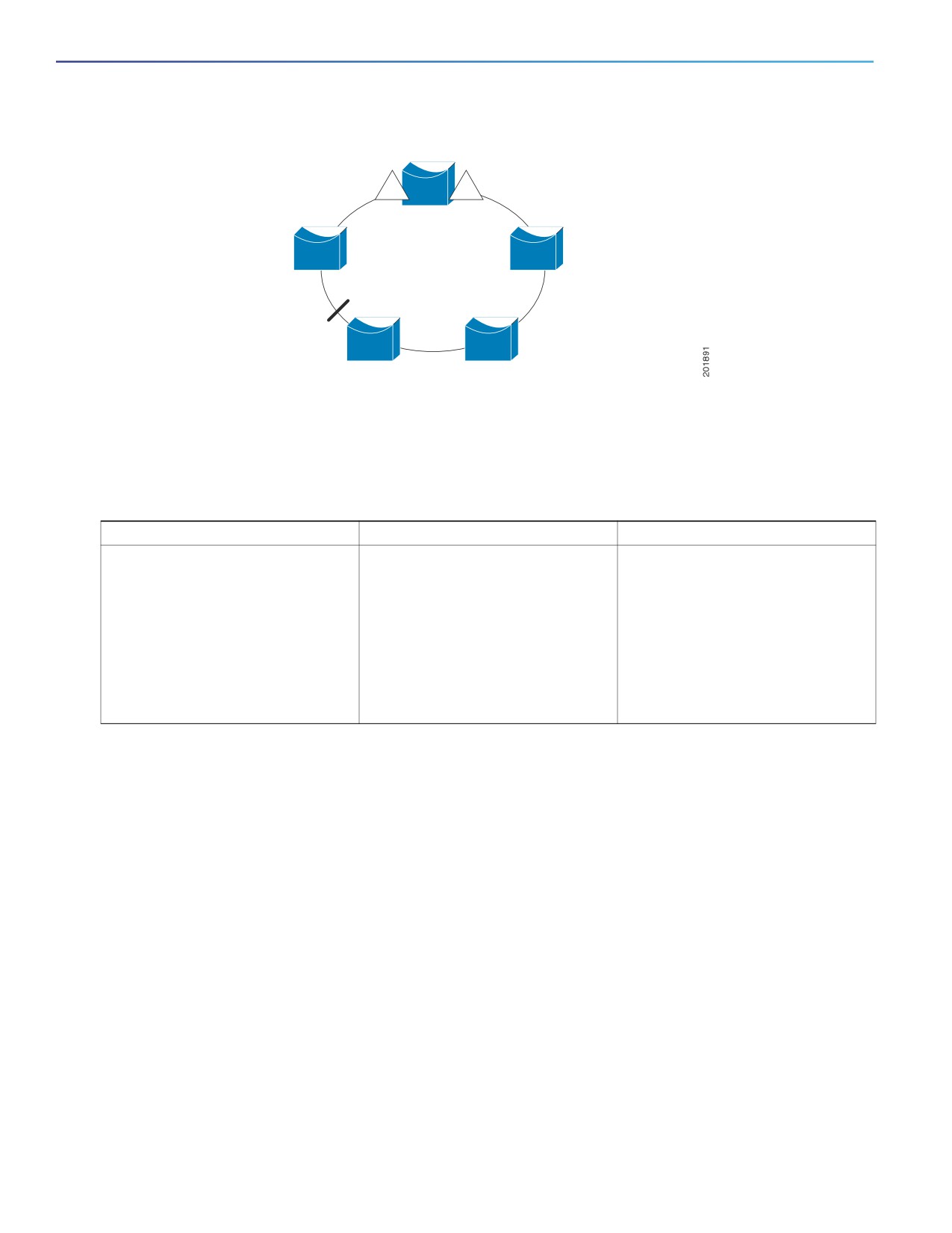
This example shows how to configure the VLAN blocking configuration shown in Figure 56 on page 398. The alternate
port is the neighbor with neighbor offset number 4. After manual preemption, VLANs 100 to 200 are blocked at this port,
and all other VLANs are blocked at the primary edge port E1 (Gigabit Ethernet port 1/0/1).
Switch# configure terminal
Switch (conf)# interface GigabitEthernet1/17
Switch (conf-if)# rep segment 1 edge primary
Switch (conf-if)# rep block port 4 vlan 100-200
Switch (conf-if)# end
397
Configuring Resilient Ethernet Protocol
Feature History
Figure 56
Example of VLAN Blocking
Primary edge port E1
blocks all VLANs except
E1
E2
VLANs 100-200
4
Alternate port (offset 4)
blocks VLANs 100-200
Feature History
Table 46
Feature History
Feature
Release
Feature Information
REP Negotiated
15.2(8)E2
When the switch interfaces are
configured with REP Negotiated (see
REP Negotiated, page 385), REP
status is negotiated with the peers. If
the peer supports REP, it is migrated
to REP. If the peer does not support
REP, it is migrated to STP. The peer is
migrated to REP or STP using an
Embedded Event Manager (EEM)
macro.
Additional References
The following sections provide references related to switch administration:
398
Configuring Resilient Ethernet Protocol
Additional References
Related Documents
Related Topic
Document Title
Cisco IOS basic commands
Cisco IOS Configuration Fundamentals Command Reference
Standards
Standards
Title
No new or modified standards are supported by this
—
feature, and support for existing standards has not
been modified by this feature.
MIBs
MIBs
MIBs Link
—
To locate and download MIBs using Cisco IOS XR software, use the
Cisco MIB Locator found at the following URL and choose a platform
under the Cisco Access Products menu:
RFCs
RFCs
Title
No new or modified RFCs are supported by this
—
feature, and support for existing RFCs has not been
modified by this feature.
399
Configuring Resilient Ethernet Protocol
Additional References
400
Configuring FlexLinks and the MAC
Address-Table Move Update
Restrictions for the FlexLinks and the MAC Address-Table Move
Update
To use this feature, the switch must be running the LAN Base image.
Information About Configuring the FlexLinks and the MAC
Address-Table Move Update
FlexLinks
FlexLinks are a pair of a Layer 2 interfaces (switch ports or port channels) where one interface is configured to act as a
backup to the other. The feature provides an alternative solution to the Spanning Tree Protocol (STP). Users can disable
STP and still retain basic link redundancy. FlexLinks are typically configured in service provider or enterprise networks
where customers do not want to run STP on the switch. If the switch is running STP, FlexLinks is not necessary because
STP already provides link-level redundancy or backup.
You configure FlexLinks on one Layer 2 interface (the active link) by assigning another Layer 2 interface as the FlexLinks
or backup link. When one of the links is up and forwarding traffic, the other link is in standby mode, ready to begin
forwarding traffic if the other link shuts down. At any given time, only one of the interfaces is in the linkup state and
forwarding traffic. If the primary link shuts down, the standby link starts forwarding traffic. When the active link comes
back up, it goes into standby mode and does not forward traffic. STP is disabled on FlexLinks interfaces.
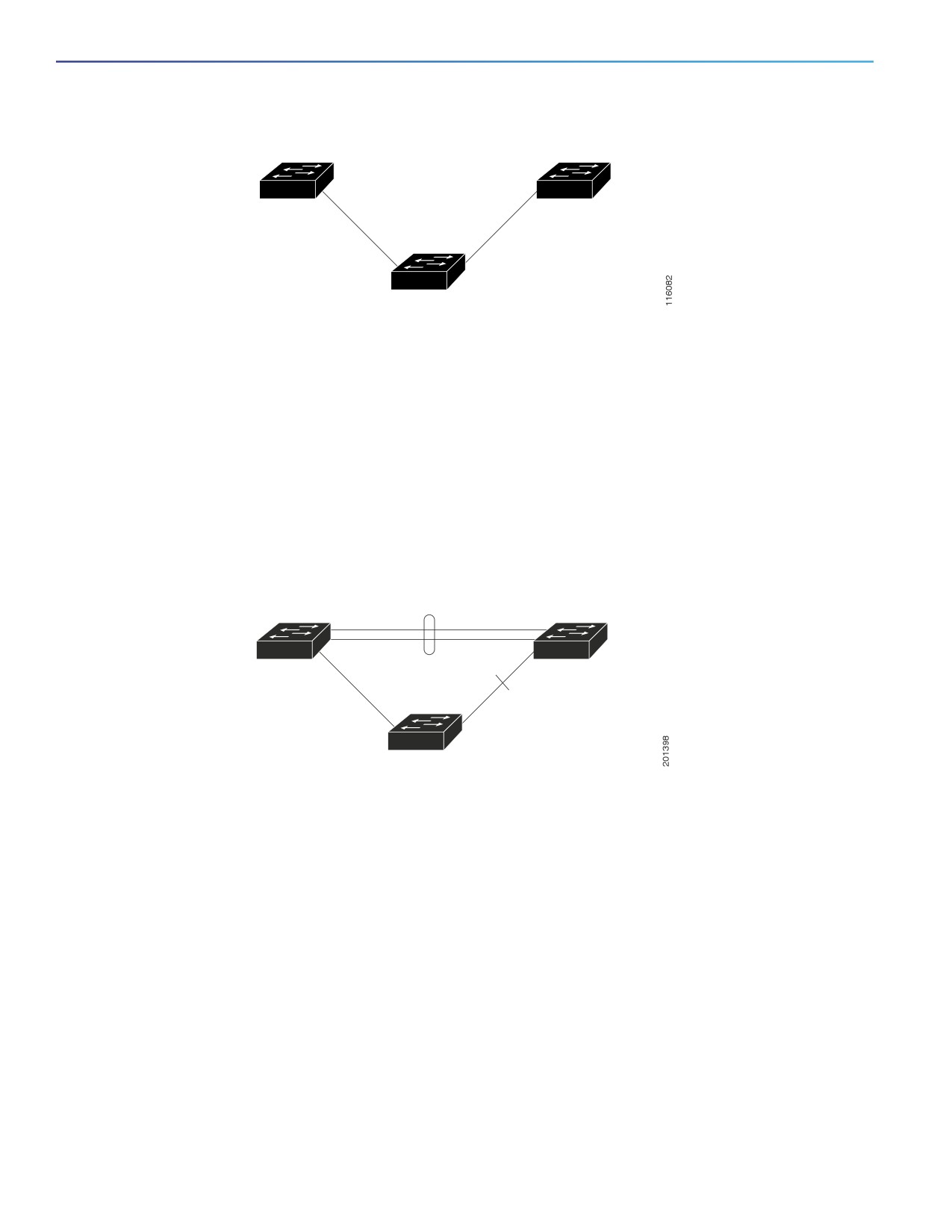
In Figure 57 on page 402, ports 1 and 2 on switch A are connected to uplink switches B and C. Because they are
configured as FlexLinks, only one of the interfaces is forwarding traffic; the other is in standby mode. If port 1 is the active
link, it begins forwarding traffic between port 1 and switch B; the link between port 2 (the backup link) and switch C is
not forwarding traffic. If port 1 goes down, port 2 comes up and starts forwarding traffic to switch C. When port 1 comes
back up, it goes into standby mode and does not forward traffic; port 2 continues forwarding traffic.
You can also choose to configure a preemption mechanism, specifying the preferred port for forwarding traffic. For
example, in the example in Figure 57 on page 402, you can configure the FlexLinks pair with preemption mode. In the
scenario shown, when port 1 comes back up and has more bandwidth than port 2, port 1 begins forwarding traffic after
60 seconds. Port 2 becomes the standby port. You do this by entering the interface configuration switchport backup
interface preemption mode bandwidth and switchport backup interface preemption delay commands.
401
Configuring FlexLinks and the MAC Address-Table Move Update
Information About Configuring the FlexLinks and the MAC Address-Table Move Update
Figure 57
FlexLinks Configuration Example
Uplink
Uplink
switch B
switch C
Port 1
Port 2
Switch A
If a primary (forwarding) link goes down, a trap notifies the network management stations. If the standby link goes down,
a trap notifies the users.
FlexLinks are supported only on Layer 2 ports and port channels, not on VLANs or on Layer 3 ports.
VLAN FlexLinks Load Balancing and Support
VLAN FlexLinks load-balancing allows you to configure a FlexLinks pair so that both ports simultaneously forward the
traffic for some mutually exclusive VLANs. For example, if FlexLinks ports are configured for 1 to100 VLANs, the traffic
of the first 50 VLANs can be forwarded on one port and the rest on the other port. If one of the ports fail, the other active
port forwards all the traffic. When the failed port comes back up, it resumes forwarding traffic in the preferred VLANs.
This way, apart from providing the redundancy, this FlexLinks pair can be used for load balancing. FlexLinks VLAN load
balancing does not impose any restrictions on uplink switches.
Figure 58
VLAN FlexLinks Load Balancing Configuration Example
Uplink
Uplink
switch B
switch C
Forwarding
Forwarding
(1-50)
(51-100)
gi2/0/6
gi2/0/8
Switch A
FlexLinks Multicast Fast Convergence
FlexLinks Multicast Fast Convergence reduces the multicast traffic convergence time after a FlexLinks failure.
Learning the Other FlexLinks Port as the mrouter Port
In a typical multicast network, there is a querier for each VLAN. A switch deployed at the edge of a network has one of
its FlexLinks ports receiving queries. FlexLinks ports are also always forwarding at any given time.
A port that receives queries is added as an mrouter port on the switch. An mrouter port is part of all the multicast groups
learned by the switch. After a changeover, queries are received by the other FlexLinks port. The other FlexLinks port is
then learned as the mrouter port. After the changeover, multicast traffic flows through the other FlexLinks port. To achieve
faster convergence of traffic, both FlexLinks ports are learned as mrouter ports whenever either FlexLinks port is learned
as the mrouter port. Both FlexLinks ports are always part of multicast groups.
Though both FlexLinks ports are part of the groups in normal operation mode, all traffic on the backup port is blocked.
So the normal multicast data flow is not affected by the addition of the backup port as an mrouter port. When the
changeover happens, the backup port is unblocked, allowing the traffic to flow. In this case, the upstream multicast data
flows as soon as the backup port is unblocked.
402
Configuring FlexLinks and the MAC Address-Table Move Update
Information About Configuring the FlexLinks and the MAC Address-Table Move Update
Generating IGMP Reports
When the backup link comes up after the changeover, the upstream new distribution switch does not start forwarding
multicast data, because the port on the upstream router, which is connected to the blocked FlexLinks port, is not part of
any multicast group. The reports for the multicast groups were not forwarded by the downstream switch because the
backup link is blocked. The data does not flow on this port, until it learns the multicast groups, which occurs only after it
receives reports.
The reports are sent by hosts when a general query is received, and a general query is sent within 60 seconds in normal
scenarios. When the backup link starts forwarding, to achieve faster convergence of multicast data, the downstream
switch immediately sends proxy reports for all the learned groups on this port without waiting for a general query.
Leaking IGMP Reports
To achieve multicast traffic convergence with minimal loss, a redundant data path must be set up before the FlexLinks
active link goes down. This can be achieved by leaking only IGMP report packets on the FlexLinks backup link. These
leaked IGMP report messages are processed by upstream distribution routers, so multicast data traffic gets forwarded
to the backup interface. Because all incoming traffic on the backup interface is dropped at the ingress of the access
switch, no duplicate multicast traffic is received by the host. When the FlexLinks active link fails, the access switch starts
accepting traffic from the backup link immediately. The only disadvantage of this scheme is that it consumes bandwidth
on the link between the distribution switches and on the backup link between the distribution and access switches. This
feature is disabled by default and can be configured by using the switchport backup interface interface-id multicast
fast-convergence command.
When this feature has been enabled at changeover, the switch does not generate the proxy reports on the backup port,
which became the forwarding port.
MAC Address-Table Move Update
The MAC address-table move update feature allows the switch to provide rapid bidirectional convergence when a
primary (forwarding) link goes down and the standby link begins forwarding traffic.
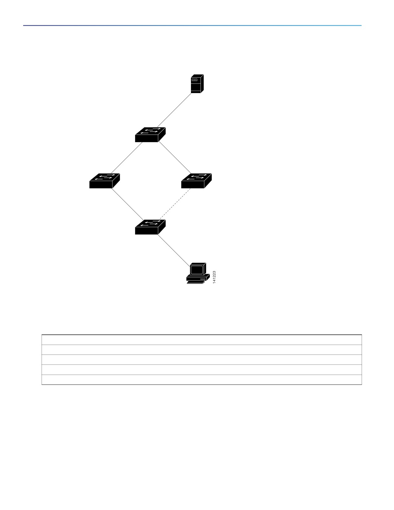
In Figure 59 on page 404, switch A is an access switch, and ports 1 and 2 on switch A are connected to uplink switches
B and D through a FlexLinks pair. Port 1 is forwarding traffic, and port 2 is in the backup state. Traffic from the PC to the
server is forwarded from port 1 to port 3. The MAC address of the PC has been learned on port 3 of switch C. Traffic
from the server to the PC is forwarded from port 3 to port 1.
If the MAC address-table move update feature is not configured and port 1 goes down, port 2 starts forwarding traffic.
However, for a short time, switch C keeps forwarding traffic from the server to the PC through port 3, and the PC does
not get the traffic because port 1 is down. If switch C removes the MAC address of the PC on port 3 and relearns it on
port 4, traffic can then be forwarded from the server to the PC through port 2.
If the MAC address-table move update feature is configured and enabled on the switches in Figure 59 on page 404 and
port 1 goes down, port 2 starts forwarding traffic from the PC to the server. The switch sends a MAC address-table move
update packet from port 2. Switch C gets this packet on port 4 and immediately learns the MAC address of the PC on
port 4, which reduces the reconvergence time.
You can configure the access switch, switch A, to send MAC address-table move update messages. You can also
configure the uplink switches B, C, and D to get and process the MAC address-table move update messages. When
switch C gets a MAC address-table move update message from switch A, switch C learns the MAC address of the PC
on port 4. Switch C updates the MAC address table, including the forwarding table entry for the PC.
Switch A does not need to wait for the MAC address-table update. The switch detects a failure on port 1 and immediately
starts forwarding server traffic from port 2, the new forwarding port. This change occurs in 100 milliseconds (ms). The
PC is directly connected to switch A, and the connection status does not change. Switch A does not need to update the
PC entry in the MAC address table.
403
Configuring FlexLinks and the MAC Address-Table Move Update
Information About Configuring the FlexLinks and the MAC Address-Table Move Update
Figure 59
MAC Address-Table Move Update Example
Server
Switch C
Port 3
Port 4
Switch B
Switch D
Port 1
Port 2
Switch A
PC
Default Settings for FlexLinks and MAC Address-Table Move Update
Default Settings
FlexLinks is not configured, and there are no backup interfaces defined.
The preemption mode is off.
The preemption delay is 35 seconds.
MAC address-table move update is not configured on the switch.
Configuration Guidelines for FlexLinks and MAC Address-Table Move Update
Follow these guidelines to configure FlexLinks:
You can configure up to 16 backup links.
You can configure only one FlexLinks backup link for any active link, and it must be a different interface from the
active interface.
An interface can belong to only one FlexLinks pair. An interface can be a backup link for only one active link. An
active link cannot belong to another FlexLinks pair.
404

Configuring FlexLinks and the MAC Address-Table Move Update
How to Configure the FlexLinks and MAC Address-Table Move Update
Neither of the links can be a port that belongs to an EtherChannel. However, you can configure two port channels
(EtherChannel logical interfaces) as FlexLinks, and you can configure a port channel and a physical interface as
FlexLinks, with either the port channel or the physical interface as the active link.
A backup link does not have to be the same type (Gigabit Ethernet, or port channel) as the active link. However, you
should configure both FlexLinks with similar characteristics so that there are no loops or changes in behavior if the
standby link begins to forward traffic.
STP is disabled on FlexLinks ports. A FlexLinks port does not participate in STP, even if the VLANs present on the
port are configured for STP. When STP is not enabled, be sure that there are no loops in the configured topology.
Once the FlexLinks configurations are removed, STP is reenabled on the ports.
Follow these guidelines to configure VLAN load balancing on the FlexLinks feature:
For FlexLinks VLAN load balancing, you must choose the preferred VLANs on the backup interface.
You cannot configure a preemption mechanism and VLAN load balancing for the same FlexLinks pair.
Follow these guidelines to configure the MAC address-table move update feature:
You can enable and configure this feature on the access switch to send the MAC address-table move updates.
You can enable and configure this feature on the uplink switches to receive the MAC address-table move updates.
How to Configure the FlexLinks and MAC Address-Table Move
Update
Configuring FlexLinks
Command
Purpose
1.
configure terminal
Enters global configuration mode.
2.
interface interface-id
Specifies the interface, and enters interface configuration
mode. The interface can be a physical Layer 2 interface
or a port channel (logical interface). The port-channel
range is 1 to 10.
3.
switchport backup interface interface-id
Configures a physical Layer 2 interface (or port channel)
as part of a FlexLinks pair with the interface. When one
link is forwarding traffic, the other interface is in standby
mode.
4.
end
Returns to privileged EXEC mode.
405

Configuring FlexLinks and the MAC Address-Table Move Update
How to Configure the FlexLinks and MAC Address-Table Move Update
Configuring a Preemption Scheme for FlexLinks
Command
Purpose
1.
configure terminal
Enters global configuration mode.
2.
interface interface-id
Specifies the interface, and enter interface configuration
mode. The interface can be a physical Layer 2 interface
or a port channel (logical interface). The port-channel
range is 1 to 10.
3.
switchport backup interface interface-id
Configures a physical Layer 2 interface (or port channel)
as part of a FlexLinks pair with the interface. When one
link is forwarding traffic, the other interface is in standby
mode.
4.
switchport backup interface interface-id preemption
Configures a preemption mechanism and delay for a
mode [forced | bandwidth | off]
FlexLinks interface pair. You can configure the
preemption as:
forced—The active interface always preempts the
backup.
bandwidth—The interface with the higher bandwidth
always acts as the active interface.
off—No preemption happens from active to backup.
5.
switchport backup interface interface-id preemption
Configures the time delay until a port preempts another
delay delay-time
port.
Note: Setting a delay time only works with forced and
bandwidth modes.
6.
end
Returns to privileged EXEC mode.
Configuring VLAN Load Balancing on FlexLinks
Command
Purpose
1.
configure terminal
Enters global configuration mode.
2.
interface interface-id
Specifies the interface, and enters interface configuration
mode. The interface can be a physical Layer 2 interface
or a port channel (logical interface). The port-channel
range is 1 to 10.
3.
switchport backup interface interface-id prefer vlan
Configures a physical Layer 2 interface (or port channel)
vlan-range
as part of a FlexLinks pair with the interface, and
specifies the VLANs carried on the interface. The VLAN
ID range is 1 to 4096.
4.
end
Returns to privileged EXEC mode.
406

Configuring FlexLinks and the MAC Address-Table Move Update
How to Configure the FlexLinks and MAC Address-Table Move Update
Configuring the MAC Address-Table Move Update Feature
Command
Purpose
1.
configure terminal
Enters global configuration mode.
2.
interface interface-id
Specifies the interface, and enters interface configuration
mode. The interface can be a physical Layer 2 interface
or a port channel (logical interface). The port-channel
range is 1 to 10.
3.
switchport backup interface interface-id
Configures a physical Layer 2 interface (or port channel),
as part of a FlexLinks pair with the interface. The MAC
address-table move update VLAN is the lowest VLAN ID
on the interface.
or
Configures a physical Layer 2 interface (or port channel)
switchport backup interface interface-id mmu primary
and specifies the VLAN ID on the interface, which is used
vlan vlan-id
for sending the MAC address-table move update.
When one link is forwarding traffic, the other interface is
in standby mode.
4.
end
Returns to global configuration mode.
5.
mac address-table move update transmit
Enables the access switch to send MAC address-table
move updates to other switches in the network if the
primary link goes down and the switch starts forwarding
traffic through the standby link.
6.
end
Returns to privileged EXEC mode.
Configuring the MAC Address-Table Move Update Messages
Command
Purpose
1.
configure terminal
Enters global configuration mode.
2.
mac address-table move update receive
Enables the switch to get and process the MAC
address-table move updates.
3.
end
Returns to privileged EXEC mode.
4.
show mac address-table move update
Verifies the configuration.
5.
copy running-config startup config
(Optional) Saves your entries in the switch startup
configuration file.
407

Configuring FlexLinks and the MAC Address-Table Move Update
Maintaining and Monitoring the FlexLinks and MAC Address-Table Move Update
Maintaining and Monitoring the FlexLinks and MAC
Address-Table Move Update
Command
Purpose
show interfaces [interface-id] switchport backup
Displays the FlexLinks backup interface configured
for an interface or all the configured FlexLinks and
the state of each active and backup interface (up or
standby mode). When VLAN load balancing is
enabled, the output displays the preferred VLANs
on active and backup interfaces.
show mac address-table move update
Verifies the configuration.
Configuration Examples for the FlexLinks and MAC
Address-Table Move Update
Configuring FlexLinks Port: Examples
These are configuration examples for learning the other FlexLinks port as the mrouter port when FlexLinks is configured,
with output for the show interfaces switchport backup command:
This output shows a querier for VLANs 1 and 401, with their queries reaching the switch through the specified port:
Switch# show ip igmp snooping querier
Vlan
IP Address
IGMP Version
Port
-------------------------------------------------------------
1
1.1.1.1
v2
Gi0/1
401
41.41.41.1
v2
Gi0/1
Here is output for the show ip igmp snooping mrouter command for VLANs 1 and 401:
Switch# show ip igmp snooping mrouter
Vlan
ports
----
-----
1
Gi1/17(dynamic), Gi1/18(dynamic)
401
Gi1/17(dynamic), Gi1/18(dynamic)
Similarly, both FlexLinks ports are part of learned groups. In this example, GigabitEthernet1/17 is a receiver/host in VLAN
1, which is interested in two multicast groups:
Switch# show ip igmp snooping groups
Vlan
Group
Type
Version
Port List
-----------------------------------------------------------------------
1
228.1.5.1 igmp
v2
Gi1/17, Gi1/18, Fa2/1
1
228.1.5.2 igmp
v2
Gi1/17, Gi1/18, Fa2/1
When a host responds to the general query, the switch forwards this report on all the mrouter ports. In this example,
when a host sends a report for the group 228.1.5.1, it is forwarded only on GigabitEthernet1/17, because the backup
port GigabitEthernet1/18 is blocked. When the active link, GigabitEthernet1/17, goes down, the backup port,
GigabitEthernet1/18, begins forwarding.
As soon as this port starts forwarding, the switch sends proxy reports for the groups 228.1.5.1 and 228.1.5.2 on behalf
of the host. The upstream router learns the groups and starts forwarding multicast data. This is the default behavior of
FlexLinks. This behavior changes when the user configures fast convergence using the switchport backup interface
GigabitEthernet1/18 multicast fast-convergence command. This example shows how this feature is configured:
408
Configuring FlexLinks and the MAC Address-Table Move Update
Configuration Examples for the FlexLinks and MAC Address-Table Move Update
Switch# configure terminal
Enter configuration commands, one per line. End with CNTL/Z.
Switch(config)# interface GigabitEthernet1/17
Switch(config-if)# switchport backup interface GigabitEthernet1/18 multicast fast-convergence
Switch(config-if)# exit
Switch# show interfaces switchport backup detail
Switch Backup Interface Pairs:
Active
Interface
Backup Interface State
------------------------------------------------------------------------
GigabitEthernet1/17 GigabitEthernet1/18 Active Up/Backup Standby
Preemption Mode : off
Multicast Fast Convergence : On
Mac Address Move Update Vlan : auto
This output shows a querier for VLAN 1 and 401 with their queries reaching the switch through the configured port:
Switch# show ip igmp snooping querier
Vlan
IP Address
IGMP Version
Port
-------------------------------------------------------------
1
1.1.1.1
v2
Gi1/17
401
41.41.41.1
v2
Gi1/17
This is output for the show ip igmp snooping mrouter command for VLAN 1 and 401:
Switch# show ip igmp snooping mrouter
Vlan
ports
----
-----
1
Gi1/17(dynamic), Gi1/18(dynamic)
401
Gi1/17(dynamic), Gi1/18(dynamic)
Similarly, both the FlexLinks ports are a part of the learned groups. In this example, the port is a receiver/host in VLAN
1, which is interested in two multicast groups:
Switch# show ip igmp snooping groups
Vlan
Group
Type
Version
Port List
-----------------------------------------------------------------------
1
228.1.5.1 igmp
v2
Gi1/17, Gi1/18, Gi1/17
1
228.1.5.2 igmp
v2
Gi1/17, Gi1/18, Gi1/17
Whenever a host responds to the general query, the switch forwards this report on all the mrouter ports. When you turn
on this feature through the command-line port, and when a report is forwarded by the switch on the configured
GigabitEthernet1/17, it is also leaked to the backup port GigabitEthernet1/18. The upstream router learns the groups and
starts forwarding multicast data, which is dropped at the ingress because the GigabitEthernet1/18 is blocked. When the
active link, GigabitEthernet1/17 goes down, the backup port, GigabitEthernet1/18, begins forwarding. You do not need
to send any proxy reports because the multicast data is already being forwarded by the upstream router. By leaking
reports to the backup port, a redundant multicast path has been set up, and the time taken for the multicast traffic
convergence is minimal.
Configuring a Backup Interface: Example
This example shows how to configure an interface with a backup interface and to verify the configuration:
Switch# configure terminal
Switch(conf)# interface GigabitEthernet1/17
Switch(conf-if)# switchport backup interface GigabitEthernet1/18
Switch(conf-if)# end
Switch# show interfaces switchport backup
Switch Backup Interface Pairs:
409
Configuring FlexLinks and the MAC Address-Table Move Update
Configuration Examples for the FlexLinks and MAC Address-Table Move Update
Active Interface
Backup Interface
State
------------------------------------------------------------------------
Vlans Preferred on Active Interface: 1-3,5-4096
Vlans Preferred on Backup Interface: 4
Configuring a Preemption Scheme: Example
This example shows how to configure the preemption mode as forced for a backup interface pair and to verify the
configuration:
Switch# configure terminal
Switch(conf)# interface GigabitEthernet1/17
Switch(conf-if)#switchport backup interface GigabitEthernet1/18 preemption mode forced
Switch(conf-if)#switchport backup interface GigabitEthernet1/18 preemption delay 50
Switch(conf-if)# end
Switch# show interfaces switchport backup detail
Active Interface Backup Interface State
------------------------------------------------------------------------
GigabitEthernet1/17 GigabitEthernet1/18 Active Up/Backup Standby
Interface Pair : Gi1/17, Gi1/18
Preemption Mode : forced
Preemption Delay : 50 seconds
Bandwidth : 100000 Kbit (Gi1/17), 100000 Kbit (Gi1/18)
Mac Address Move Update Vlan : auto
Configuring VLAN Load Balancing on FlexLinks: Examples
In the following example, VLANs 1 to 50, 60, and 100 to 120 are configured on the switch:
Switch(config)# interface gigabitEthernet 1/2
Switch(config-if)# switchport backup interface gigabitEthernet 1/2 prefer vlan 60,100-120
When both interfaces are up, GigabitEthernet1/17 forwards traffic for VLANs 60 and 100 to 120, and GigabitEthernet1/18
forwards traffic for VLANs 1 to 50.
Switch# show interfaces switchport backup
Switch Backup Interface Pairs:
Active Interface
Backup Interface
State
------------------------------------------------------------------------
GigabitEthernet1/17
GigabitEthernet1/18
Active Up/Backup Standby
Vlans Preferred on Active Interface: 1-50
Vlans Preferred on Backup Interface: 60, 100-120
When a FlexLinks interface goes down (LINK_DOWN), VLANs preferred on this interface are moved to the peer interface
of the FlexLinks pair. In this example, if interface Gigabit Ethernet1/1 goes down, Gigabit Ethernet1/2 carries all VLANs
of the FlexLinks pair.
Switch# show interfaces switchport backup
Switch Backup Interface Pairs:
Active Interface
Backup Interface
State
------------------------------------------------------------------------
GigabitEthernet1/17
GigabitEthernet1/18
Active Down/Backup Up
Vlans Preferred on Active Interface: 1-50
Vlans Preferred on Backup Interface: 60, 100-120
410
Configuring FlexLinks and the MAC Address-Table Move Update
Configuration Examples for the FlexLinks and MAC Address-Table Move Update
When a FlexLinks interface comes up, VLANs preferred on this interface are blocked on the peer interface and moved
to the forwarding state on the interface that has just come up. In this example, if interface Gigabit Ethernet1/1 comes up,
VLANs preferred on this interface are blocked on the peer interface Gigabit Ethernet1/2 and forwarded on Gigabit
Ethernet1/1.
Switch# show interfaces switchport backup
Switch Backup Interface Pairs:
Active Interface
Backup Interface
State
------------------------------------------------------------------------
GigabitEthernet1/17
GigabitEthernet1/18
Active Down/Backup Up
Vlans Preferred on Active Interface: 1-50
Vlans Preferred on Backup Interface: 60, 100-120
Switch# show interfaces switchport backup detail
Switch Backup Interface Pairs:
Active Interface
Backup Interface
State
------------------------------------------------------------------------
FastEthernet1/3
FastEthernet1/4
Active Down/Backup Up
Vlans Preferred on Active Interface: 1-2,5-4096
Vlans Preferred on Backup Interface: 3-4
Preemption Mode
: off
Bandwidth : 10000 Kbit (Fa1/3), 100000 Kbit (Fa1/4)
Mac Address Move Update Vlan : auto
Configuring MAC Address-Table Move Update: Example
This example shows how to configure an access switch to send MAC address-table move update messages:
Switch(conf)# interface GigabitEthernet1/17
Switch(conf-if)# switchport backup interface GigabitEthernet1/18 mmu primary vlan 2
Switch(conf-if)# exit
Switch(conf)# mac address-table move update transmit
Switch(conf)# end
This example shows how to verify the configuration:
Switch# show mac-address-table move update
Switch-ID : 010b.4630.1780
Dst mac-address : 0180.c200.0010
Vlans/Macs supported : 1023/8320
Default/Current settings: Rcv Off/On, Xmt Off/On
Max packets per min : Rcv 40, Xmt 60
Rcv packet count : 5
Rcv conforming packet count : 5
Rcv invalid packet count : 0
Rcv packet count this min : 0
Rcv threshold exceed count : 0
Rcv last sequence# this min : 0
Rcv last interface : Po2
Rcv last src-mac-address : 000b.462d.c502
Rcv last switch-ID : 0403.fd6a.8700
Xmt packet count : 0
Xmt packet count this min : 0
Xmt threshold exceed count : 0
Xmt pak buf unavail cnt : 0
Xmt last interface : None
411

Configuring FlexLinks and the MAC Address-Table Move Update
Additional References
Additional References
The following sections provide references related to switch administration:
Related Documents
Related Topic
Document Title
Cisco IOS basic commands
Cisco IOS Configuration Fundamentals Command Reference
Standards
Standards
Title
No new or modified standards are supported by this
—
feature, and support for existing standards has not
been modified by this feature.
MIBs
MIBs
MIBs Link
—
To locate and download MIBs using Cisco IOS XR software, use the
Cisco MIB Locator found at the following URL and choose a platform
under the Cisco Access Products menu:
RFCs
RFCs
Title
No new or modified RFCs are supported by this
—
feature, and support for existing RFCs has not been
modified by this feature.
412
Configuring DHCP
Information About Configuring DHCP
This chapter describes how to configure Dynamic Host Configuration Protocol (DHCP) snooping and option-82 data
insertion, and the DHCP server port-based address allocation features on the switch. It also describes how to configure
the IP source guard feature.
DHCP Snooping
DHCP is widely used in LAN environments to dynamically assign host IP addresses from a centralized server, which
significantly reduces the overhead of administration of IP addresses. DHCP also helps conserve the limited IP address
space because IP addresses no longer need to be permanently assigned to hosts; only those hosts that are connected
to the network consume IP addresses.
DHCP Server
The DHCP server assigns IP addresses from specified address pools on a switch or router to DHCP clients and manages
them. If the DHCP server cannot give the DHCP client the requested configuration parameters from its database, it
forwards the request to one or more secondary DHCP servers defined by the network administrator.
DHCP Relay Agent
A DHCP relay agent is a Layer 3 device that forwards DHCP packets between clients and servers. Relay agents forward
requests and replies between clients and servers when they are not on the same physical subnet. Relay agent forwarding
is different from the normal Layer 2 forwarding, in which IP datagrams are switched transparently between networks.
Relay agents receive DHCP messages and generate new DHCP messages to send on output interfaces.
DHCP Snooping
DHCP snooping is a DHCP security feature that provides network security by filtering untrusted DHCP messages and by
building and maintaining a DHCP snooping binding database, also referred to as a DHCP snooping binding table.
DHCP snooping acts like a firewall between untrusted hosts and DHCP servers. You use DHCP snooping to differentiate
between untrusted interfaces connected to the end user and trusted interfaces connected to the DHCP server or another
switch.
Note: For DHCP snooping to function properly, all DHCP servers must be connected to the switch through trusted
interfaces.
An untrusted DHCP message is a message that is received from outside the network or firewall. When you use DHCP
snooping in a service-provider environment, an untrusted message is sent from a device that is not in the
service-provider network, such as a customer’s switch. Messages from unknown devices are untrusted because they
can be sources of traffic attacks.
413
Configuring DHCP
Information About Configuring DHCP
The DHCP snooping binding database has the MAC address, the IP address, the lease time, the binding type, the VLAN
number, and the interface information that corresponds to the local untrusted interfaces of a switch. It does not have
information regarding hosts interconnected with a trusted interface.
In a service-provider network, a trusted interface is connected to a port on a device in the same network. An untrusted
interface is connected to an untrusted interface in the network or to an interface on a device that is not in the network.
When a switch receives a packet on an untrusted interface and the interface belongs to a VLAN in which DHCP snooping
is enabled, the switch compares the source MAC address and the DHCP client hardware address. If the addresses match
(the default), the switch forwards the packet. If the addresses do not match, the switch drops the packet.
The switch drops a DHCP packet when one of these situations occurs:
A packet from a DHCP server, such as a DHCPOFFER, DHCPACK, DHCPNAK, or DHCPLEASEQUERY packet, is
received from outside the network or firewall.
A packet is received on an untrusted interface, and the source MAC address and the DHCP client hardware address
do not match.
The switch receives a DHCPRELEASE or DHCPDECLINE broadcast message that has a MAC address in the DHCP
snooping binding database, but the interface information in the binding database does not match the interface on
which the message was received.
A DHCP relay agent forwards a DHCP packet that includes a relay-agent IP address that is not 0.0.0.0, or the relay
agent forwards a packet that includes option-82 information to an untrusted port.
If the switch is an aggregation switch supporting DHCP snooping and is connected to an edge switch that is inserting
DHCP option-82 information, the switch drops packets with option-82 information when packets are received on an
untrusted interface. If DHCP snooping is enabled and packets are received on a trusted port, the aggregation switch does
not learn the DHCP snooping bindings for connected devices and cannot build a complete DHCP snooping binding
database.
When an aggregation switch can be connected to an edge switch through an untrusted interface and you enter the ip
dhcp snooping information option allow-untrusted global configuration command, the aggregation switch accepts
packets with option-82 information from the edge switch. The aggregation switch learns the bindings for hosts
connected through an untrusted switch interface. The DHCP security features, such as dynamic ARP inspection or IP
source guard, can still be enabled on the aggregation switch while the switch receives packets with option-82
information on untrusted input interfaces to which hosts are connected. The port on the edge switch that connects to
the aggregation switch must be configured as a trusted interface.
Option-82 Data Insertion
In residential, metropolitan Ethernet-access environments, DHCP can centrally manage the IP address assignments for
a large number of subscribers. When the DHCP option-82 feature is enabled on the switch, a subscriber device is
identified by the switch port through which it connects to the network (in addition to its MAC address). Multiple hosts on
the subscriber LAN can be connected to the same port on the access switch and are uniquely identified.
Note: The DHCP option-82 feature is supported only when DHCP snooping is globally enabled and on the VLANs to
which subscriber devices using this feature are assigned.
Figure 60 on page 415 is an example of a metropolitan Ethernet network in which a centralized DHCP server assigns IP
addresses to subscribers connected to the switch at the access layer. Because the DHCP clients and their associated
DHCP server do not reside on the same IP network or subnet, a DHCP relay agent (the Catalyst switch) is configured with
a helper address to enable broadcast forwarding and to transfer DHCP messages between the clients and the server.
414
Configuring DHCP
Information About Configuring DHCP
Figure 60
DHCP Relay Agent in a Metropolitan Ethernet Network
DHCP
server
Catalyst switch
Access layer
(DHCP relay agent)
VLAN 10
Host A
Subscribers
Host B
(DHCP client)
(DHCP client)
When you enable the DHCP snooping information option-82 on the switch, this sequence of events occurs:
The host (DHCP client) generates a DHCP request and broadcasts it on the network.
When the switch receives the DHCP request, it adds the option-82 information in the packet. By default, the
remote-ID suboption is the switch MAC address, and the circuit-ID suboption is the port identifier, vlan-mod-port,
from which the packet is received.
If the IP address of the relay agent is configured, the switch adds this IP address in the DHCP packet.
The switch forwards the DHCP request that includes the option-82 field to the DHCP server.
The DHCP server receives the packet. If the server is option-82-capable, it can use the remote ID, the circuit ID, or
both to assign IP addresses and implement policies, such as restricting the number of IP addresses that can be
assigned to a single remote ID or circuit ID. The DHCP server then repeats the option-82 field in the DHCP reply.
The DHCP server unicasts the reply to the switch if the request was relayed to the server by the switch. The switch
verifies that it originally inserted the option-82 data by inspecting the remote ID and possibly the circuit ID fields. The
switch removes the option-82 field and forwards the packet to the switch port that connects to the DHCP client that
sent the DHCP request.
In the default suboption configuration, when the described sequence of events occurs, the values in these fields in
Figure 61 on page 416 do not change:
Circuit-ID suboption fields
— Suboption type
— Length of the suboption type
— Circuit-ID type
— Length of the circuit-ID type
Remote-ID suboption fields
— Suboption type
— Length of the suboption type
— Remote-ID type
415

Configuring DHCP
Information About Configuring DHCP
— Length of the remote-ID type
In the port field of the circuit-ID suboption, the port numbers start at 3. Figure 61 on page 416 shows the packet formats
for the remote-ID suboption and the circuit-ID suboption when the default suboption configuration is used. The switch
uses the packet formats when you globally enable DHCP snooping and enter the ip dhcp snooping information option
global configuration command.
Figure 61
Suboption Packet Formats
Circuit ID Suboption Frame Format
Suboption
Circuit
type
ID type
Length
Length
1
6
0
4
VLAN
Module
Port
1 byte 1 byte 1 byte 1 byte
2 bytes
1 byte 1 byte
Remote ID Suboption Frame Format
Suboption
Remote
type
ID type
Length
Length
2
8
0
6
MAC address
1 byte 1 byte 1 byte 1 byte
6 bytes
on page 417 shows the packet formats for user-configured remote-ID and circuit-ID suboptions The switch uses these
packet formats when DHCP snooping is globally enabled and when the ip dhcp snooping information option format
remote-id global configuration command and the ip dhcp snooping vlan information option format-type circuit-id
string interface configuration command are entered.
The values for these fields in the packets change from the default values when you configure the remote-ID and circuit-ID
suboptions:
Circuit-ID suboption fields
— The circuit-ID type is 1.
— The length values are variable, depending on the length of the string that you configure.
Remote-ID suboption fields
— The remote-ID type is 1.
— The length values are variable, depending on the length of the string that you configure.
416

Configuring DHCP
Information About Configuring DHCP
Figure 62
User-Configured Suboption Packet Formats
Circuit ID Suboption Frame Format (for user-configured string):
Suboption
Circuit
type
ID type
Length
Length
1
N+2
1
N
ASCII Circuit ID string
1 byte
1 byte 1 byte 1 byte N bytes (N = 3-63)
Remote ID Suboption Frame Format (for user-configured string):
Suboption
Remote
type
ID type
Length
Length
2
N+2
1
N
ASCII Remote ID string or hostname
1 byte 1 byte 1 byte 1 byte
N bytes (N = 1-63)
Cisco IOS DHCP Server Database
During the DHCP-based autoconfiguration process, the designated DHCP server uses the Cisco IOS DHCP server
database. It has IP addresses, address bindings, and configuration parameters, such as the boot file.
An address binding is a mapping between an IP address and a MAC address of a host in the Cisco IOS DHCP server
database. You can manually assign the client IP address, or the DHCP server can allocate an IP address from a DHCP
address pool.
DHCP Snooping Binding Database
When DHCP snooping is enabled, the switch uses the DHCP snooping binding database to store information about
untrusted interfaces. The database can have up to 8192 bindings.
Each database entry (binding) has an IP address, an associated MAC address, the lease time (in hexadecimal format),
the interface to which the binding applies, and the VLAN to which the interface belongs. The database agent stores the
bindings in a file at a configured location. At the end of each entry is a checksum that accounts for all the bytes from the
start of the file through all the bytes associated with the entry. Each entry is 72 bytes, followed by a space and then the
checksum value.
To keep the bindings when the switch reloads, you must use the DHCP snooping database agent. If the agent is disabled,
dynamic ARP inspection or IP source guard is enabled, and the DHCP snooping binding database has dynamic bindings,
the switch loses its connectivity. If the agent is disabled and only DHCP snooping is enabled, the switch does not lose
its connectivity, but DHCP snooping might not prevent DHCP spoofing attacks.
When reloading, the switch reads the binding file to build the DHCP snooping binding database. The switch updates the
file when the database changes.
When a switch learns of new bindings or when it loses bindings, the switch immediately updates the entries in the
database. The switch also updates the entries in the binding file. The frequency at which the file is updated is based on
a configurable delay, and the updates are batched. If the file is not updated in a specified time (set by the write-delay
and abort-timeout values), the update stops.
417

Configuring DHCP
Information About Configuring DHCP
This is the format of the file with bindings:
<initial-checksum>
TYPE DHCP-SNOOPING
VERSION 1
BEGIN
<entry-1> <checksum-1>
<entry-2> <checksum-1-2>
<entry-n> <checksum-1-2-..-n>
END
Each entry in the file is tagged with a checksum value that the switch uses to verify the entries when it reads the file. The
initial-checksum entry on the first line distinguishes entries associated with the latest file update from entries associated
with a previous file update.
This is an example of a binding file:
2bb4c2a1
TYPE DHCP-SNOOPING
VERSION 1
BEGIN
192.1.168.1 3 0003.47d8.c91f 2BB6488E interface-id 21ae5fbb
192.1.168.3 3 0003.44d6.c52f 2BB648EB interface-id 1bdb223f
192.1.168.2 3 0003.47d9.c8f1 2BB648AB interface-id 584a38f0
END
When the switch starts and the calculated checksum value equals the stored checksum value, the switch reads entries
from the binding file and adds the bindings to its DHCP snooping binding database. The switch ignores an entry when
one of these situations occurs:
The switch reads the entry and the calculated checksum value does not equal the stored checksum value. The entry
and the ones following it are ignored.
An entry has an expired lease time (the switch might not remove a binding entry when the lease time expires).
The interface in the entry no longer exists on the system.
The interface is a routed interface or a DHCP snooping-trusted interface.
Default DHCP Snooping Settings
Table 47
Default DHCP Snooping Settings
Feature
Default Setting
DHCP server
Enabled in Cisco IOS software, requires configuration1
DHCP relay agent
Enabled2
DHCP packet forwarding address
None configured
Checking the relay agent information
Enabled (invalid messages are dropped)2. on page 419
DHCP relay agent forwarding policy
Replace the existing relay agent information2. on page 419
DHCP snooping enabled globally
Disabled
DHCP snooping information option
Enabled
DHCP snooping option to accept packets on
Disabled
untrusted input interfaces3
DHCP snooping limit rate
None configured
418

Configuring DHCP
Information About Configuring DHCP
Table 47
Default DHCP Snooping Settings (continued)
Feature
Default Setting
DHCP snooping trust
Untrusted
DHCP snooping VLAN
Disabled
DHCP snooping MAC address verification
Enabled
Cisco IOS DHCP server binding database
Enabled in Cisco IOS software, requires configuration.
Note: The switch gets network addresses and configuration parameters
only from a device configured as a DHCP server.
DHCP snooping binding database agent
Enabled in Cisco IOS software, requires configuration. This feature is
operational only when a destination is configured.
1. The switch responds to DHCP requests only if it is configured as a DHCP server.
2. The switch relays DHCP packets only if the IP address of the DHCP server is configured on the SVI of the DHCP client.
3. Use this feature when the switch is an aggregation switch that receives packets with option-82 information from an edge
switch.
DHCP Snooping Configuration Guidelines
You must globally enable DHCP snooping on the switch.
DHCP snooping is not active until DHCP snooping is enabled on a VLAN.
Before globally enabling DHCP snooping on the switch, make sure that the devices acting as the DHCP server and
the DHCP relay agent are configured and enabled.
Before configuring the DHCP snooping information option on your switch, be sure to configure the device that is
acting as the DHCP server. For example, you must specify the IP addresses that the DHCP server can assign or
exclude, or you must configure DHCP options for these devices.
When configuring a large number of circuit IDs on a switch, consider the impact of lengthy character serstrings on
the NVRAM or the flash memory. If the circuit-ID configurations, combined with other data, exceed the capacity of
the NVRAM or the flash memory, an error message appears.
Before configuring the DHCP relay agent on your switch, make sure to configure the device that is acting as the DHCP
server. For example, you must specify the IP addresses that the DHCP server can assign or exclude, configure DHCP
options for devices, or set up the DHCP database agent.
If the DHCP relay agent is enabled but DHCP snooping is disabled, the DHCP option-82 data insertion feature is not
supported.
If a switch port is connected to a DHCP server, configure a port as trusted by entering the ip dhcp snooping trust
interface configuration command.
If a switch port is connected to a DHCP client, configure a port as untrusted by entering the no ip dhcp snooping
trust interface configuration command.
Do not enter the ip dhcp snooping information option allow-untrusted command on an aggregation switch to
which an untrusted device is connected. If you enter this command, an untrusted device might spoof the option-82
information.
You can display DHCP snooping statistics by entering the show ip dhcp snooping statistics user EXEC command,
and you can clear the snooping statistics counters by entering the clear ip dhcp snooping statistics privileged EXEC
command.
419
Configuring DHCP
Information About Configuring DHCP
Note: Do not enable DHCP snooping on RSPAN VLANs. If DHCP snooping is enabled on RSPAN VLANs, DHCP
packets might not reach the RSPAN destination port.
DHCP Snooping Binding Database Guidelines
Because both NVRAM and the flash memory have limited storage capacity, we recommend that you store the binding
file on a TFTP server.
For network-based URLs (such as TFTP and FTP), you must create an empty file at the configured URL before the
switch can write bindings to the binding file at that URL. See the documentation for your TFTP server to determine
whether you must first create an empty file on the server; some TFTP servers cannot be configured this way.
To ensure that the lease time in the database is accurate, we recommend that you enable and configure NTP. For
more information, see Configuring Time and Date Manually, page 111.
If NTP is configured, the switch writes binding changes to the binding file only when the switch system clock is
synchronized with NTP.
Packet Forwarding Address
If the DHCP server and the DHCP clients are on different networks or subnets, you must configure the switch with the ip
helper-address address interface configuration command. The general rule is to configure the command on the Layer
3 interface closest to the client. The address used in the ip helper-address command can be a specific DHCP server IP
address, or it can be the network address if other DHCP servers are on the destination network segment. Using the
network address enables any DHCP server to respond to requests.
DHCP Server Port-Based Address Allocation
DHCP server port-based address allocation is a feature that enables DHCP to maintain the same IP address on an
Ethernet switch port regardless of the attached device client identifier or client hardware address.
When Ethernet switches are deployed in the network, they offer connectivity to the directly connected devices. In some
environments, such as on a factory floor, if a device fails, the replacement device must be working immediately in the
existing network. With the current DHCP implementation, there is no guarantee that DHCP would offer the same IP
address to the replacement device. Control, monitoring, and other software expect a stable IP address associated with
each device. If a device is replaced, the address assignment should remain stable even though the DHCP client has
changed.
When configured, the DHCP server port-based address allocation feature ensures that the same IP address is always
offered to the same connected port even as the client identifier or client hardware address changes in the DHCP
messages received on that port. The DHCP protocol recognizes DHCP clients by the client identifier option in the DHCP
packet. Clients that do not include the client identifier option are identified by the client hardware address. When you
configure this feature, the port name of the interface overrides the client identifier or hardware address and the actual
point of connection, the switch port, becomes the client identifier.
In all cases, by connecting the Ethernet cable to the same port, the same IP address is allocated through DHCP to the
attached device.
The DHCP server port-based address allocation feature is only supported on a Cisco IOS DHCP server and not a
third-party server.
By default, DHCP server port-based address allocation is disabled.
Port-Based Address Allocation Configuration Guidelines
These are the configuration guidelines for DHCP port-based address allocation:
420

Configuring DHCP
How to Configure DHCP
Only one IP address can be assigned per port.
Reserved addresses (preassigned) cannot be cleared by using the clear ip dhcp binding global configuration
command.
Preassigned addresses are automatically excluded from normal dynamic IP address assignment. Preassigned
addresses cannot be used in host pools, but there can be multiple preassigned addresses per DHCP address pool.
To restrict assignments from the DHCP pool to preconfigured reservations (unreserved addresses are not offered to
the client and other clients are not served by the pool), you can enter the reserved-only DHCP pool configuration
command.
How to Configure DHCP
Configuring the DHCP Relay Agent
Command
Purpose
1.
configure terminal
Enters global configuration mode.
2.
service dhcp
Enables the DHCP server and relay agent on your switch. By default, this
feature is enabled.
3.
end
Returns to privileged EXEC mode.
Specifying the Packet Forwarding Address
Command
Purpose
1.
configure terminal
Enters global configuration mode.
2.
interface vlan vlan-id
Creates a switch virtual interface by entering a VLAN
ID, and enters interface configuration mode.
3.
ip address ip-address subnet-mask
Configures the interface with an IP address and an IP
subnet.
4.
ip helper-address address
Specifies the DHCP packet forwarding address.
The helper address can be a specific DHCP server
address, or it can be the network address if other
DHCP servers are on the destination network
segment. Using the network address enables other
servers to respond to DHCP requests.
If you have multiple servers, you can configure one
helper address for each server.
5.
exit
Returns to global configuration mode.
421

Configuring DHCP
How to Configure DHCP
Command
Purpose
6.
interface range port-range
Configures multiple physical ports that are
connected to the DHCP clients, and enters interface
range configuration mode.
or
or
interface interface-id
Configures a single physical port that is connected to
the DHCP client, and enters interface configuration
mode.
7.
switchport mode access
Defines the VLAN membership mode for the port.
8.
switchport access vlan vlan-id
Assigns the ports to the same VLAN as configured in
Step 2.
9.
end
Returns to privileged EXEC mode.
Enabling DHCP Snooping and Option 82
Command
Purpose
1.
configure terminal
Enters global configuration mode.
2.
ip dhcp snooping
Enables DHCP snooping globally.
3.
ip dhcp snooping vlan vlan-range
Enables DHCP snooping on a VLAN or range of VLANs. The range is
1 to 4096.
You can enter a single VLAN ID identified by VLAN ID number, a series of
VLAN IDs separated by commas, a range of VLAN IDs separated by
hyphens, or a range of VLAN IDs separated by entering the starting and
ending VLAN IDs separated by a space.
4.
ip dhcp snooping information option
Enables the switch to insert and to remove DHCP relay information
(option-82 field) in forwarded DHCP request messages to the DHCP
server. This is the default setting.
5.
ip dhcp snooping information option
(Optional) Configures the remote-ID suboption.
format remote-id [string ASCII-string |
hostname]
You can configure the remote ID as
String of up to 63 ASCII characters (no spaces)
Hostname for the switch
Note: If the hostname is longer than 63 characters, it is truncated to 63
characters in the remote-ID configuration.
The default remote ID is the switch MAC address.
6.
ip dhcp snooping information option
(Optional) If the switch is an aggregation switch connected to an edge
allow-untrusted
switch, enable the switch to accept incoming DHCP snooping packets
with option-82 information from the edge switch.
The default setting is disabled.
Note: Enter this command only on aggregation switches that are
connected to trusted devices.
7.
interface interface-id
Specifies the interface to be configured, and enters interface
configuration mode.
422

Configuring DHCP
How to Configure DHCP
Command
Purpose
8.
ip dhcp snooping vlan vlan information
(Optional) Configures the circuit-ID suboption for the specified interface.
option format-type circuit-id
[override] string ASCII-string
Specifies the VLAN and port identifier, using a VLAN ID in the range of
1 to 4096. The default circuit ID is the port identifier in the format
vlan-mod-port.
You can configure the circuit ID to be a string of 3 to 63 ASCII characters
(no spaces).
(Optional) Use the override keyword when you do not want the circuit-ID
suboption inserted in TLV format to define subscriber information.
9.
ip dhcp snooping trust
(Optional) Configures the interface as trusted or as untrusted. Use the no
keyword to configure an interface to receive messages from an untrusted
client. The default setting is untrusted.
10.
ip dhcp snooping limit rate rate
(Optional) Configures the number of DHCP packets per second that an
interface can receive. The range is 1 to 2048. By default, no rate limit is
configured.
Note: We recommend an untrusted rate limit of not more than 100
packets per second. If you configure rate limiting for trusted interfaces,
you might need to increase the rate limit if the port is a trunk port
assigned to more than one VLAN with DHCP snooping.
11.
exit
Returns to global configuration mode.
12.
ip dhcp snooping verify mac-address
(Optional) Configures the switch to verify that the source MAC address in
a DHCP packet received on untrusted ports matches the client hardware
address in the packet. The default is to verify that the source MAC
address matches the client hardware address in the packet.
13.
end
Returns to privileged EXEC mode.
Enabling the DHCP Snooping Binding Database Agent
Command
Purpose
1.
configure terminal
Enters global configuration mode.
2.
ip dhcp snooping database
Specifies the URL for the database agent or the binding file by using one
{flash:/filename |
of these forms:
ftp://user:password@host/filename |
http://[[username:password]@]{hostna
flash:/filename
me | host-ip}[/directory]
ftp://user:password@host/filename
/image-name.tar |
rcp://user@host/filename}|
http://[[username:password]@]{hostname | host-ip}[/directory]
tftp://host/filename
/image-name.tar
rcp://user@host/filename
tftp://host/filename
3.
ip dhcp snooping database timeout
Specifies (in seconds) how long to wait for the database transfer process
seconds
to finish before stopping the process.
The default is 300 seconds. The range is 0 to 86400. Use 0 to define an
infinite duration, which means to continue trying the transfer indefinitely.
423

Configuring DHCP
How to Configure DHCP
Command
Purpose
4.
ip dhcp snooping database
Specifies the duration for which the transfer should be delayed after the
write-delay seconds
binding database changes. The range is from 15 to 86400 seconds. The
default is 300 seconds (5 minutes).
5.
end
Returns to privileged EXEC mode.
6.
ip dhcp snooping binding mac-address
(Optional) Adds binding entries to the DHCP snooping binding database.
vlan vlan-id ip-address interface
The vlan-id range is from 1 to 4904. The seconds range is from
interface-id expiry seconds
1 to 4294967295.
Enter this command for each entry that you add.
Note: Use this command when you are testing or debugging the switch.
Enabling DHCP Server Port-Based Address Allocation
Command
Purpose
1.
configure terminal
Enters global configuration mode.
2.
ip dhcp use subscriber-id client-id
Configures the DHCP server to globally use the
subscriber identifier as the client identifier on all
incoming DHCP messages.
3.
ip dhcp subscriber-id interface-name
Automatically generates a subscriber identifier
based on the short name of the interface.
A subscriber identifier configured on a specific
interface takes precedence over this command.
4.
interface interface-id
Specifies the interface to be configured, and enters
interface configuration mode.
5.
ip dhcp server use subscriber-id client-id
Configures the DHCP server to use the subscriber
identifier as the client identifier on all incoming DHCP
messages on the interface.
6.
end
Returns to privileged EXEC mode.
Preassigning an IP Address
After enabling DHCP port-based address allocation on the switch, use the ip dhcp pool global configuration command
to preassign IP addresses and to associate them to clients. To restrict assignments from the DHCP pool to preconfigured
reservations, you can enter the reserved-only DHCP pool configuration command. Unreserved addresses that are part
of the network or on pool ranges are not offered to the client, and other clients are not served by the pool. By entering
this command, users can configure a group of switches with DHCP pools that share a common IP subnet and that ignore
requests from clients of other switches.
Command
Purpose
1.
configure terminal
Enters global configuration mode.
2.
ip dhcp pool poolname
Enters DHCP pool configuration mode, and defines
the name for the DHCP pool. The pool name can be
a symbolic string (such as Engineering) or an integer
(such as 0).
3.
network network-number [mask | /prefix-length]
Specifies the subnet network number and mask of
the DHCP address pool.
424

Configuring DHCP
Monitoring and Maintaining DHCP
Command
Purpose
4.
address ip-address client-id string [ascii]
Reserves an IP address for a DHCP client identified
by the interface name.
string—Can be an ASCII value or a hexadecimal value.
5.
reserved-only
(Optional) Uses only reserved addresses in the DHCP
address pool. The default is to not restrict pool
addresses.
6.
end
Returns to privileged EXEC mode.
Monitoring and Maintaining DHCP
Command
Purpose
show interface interface id
Displays the status and configuration of a specific interface.
show ip dhcp pool
Displays the DHCP address pools.
show ip dhcp binding
Displays address bindings on the Cisco IOS DHCP server.
ip dhcp snooping database timeout seconds
Specifies (in seconds) how long to wait for the database
transfer process to finish before stopping.
ip dhcp snooping database write-delay seconds
Specifies (in seconds) the duration for which the transfer
should be delayed after the binding database changes.
clear ip dhcp snooping database statistics
Clears the DHCP snooping binding database agent statistics.
renew ip dhcp snooping database
Renews the DHCP snooping binding database.
show ip dhcp snooping database [detail]
Displays the status and statistics of the DHCP snooping
binding database agent.
show ip dhcp snooping
Displays the DHCP snooping configuration for a switch
show ip dhcp snooping binding
Displays only the dynamically configured bindings in the DHCP
snooping binding database, also referred to as a binding table.
show ip dhcp snooping database
Displays the DHCP snooping binding database status and
statistics.
show ip dhcp pool
Verifies DHCP pool configuration.
copy running-config startup-config
Saves your entries in the configuration file.
Configuration Examples for Configuring DHCP
Enabling DHCP Server Port-Based Address Allocation: Examples
In this example, a subscriber identifier is automatically generated, and the DHCP server ignores any client identifier fields
in the DHCP messages and uses the subscriber identifier instead. The subscriber identifier is based on the short name
of the interface and the client preassigned IP address 10.1.1.7.
switch# show running config
Building configuration...
Current configuration : 4899 bytes
!
version 12.2
!
425