Cisco Industrial Ethernet 4000, 4010 and 5000 Switch Software. Configuration Guide (2022) - page 15

Configuring MSTP
How to Configure MSTP
Command
Purpose
1.
configure terminal
Enters global configuration mode.
2.
spanning-tree mst instance-id root primary
Configures a switch as the root switch.
[diameter net-diameter [hello-time seconds]]
instance-id—Specifies a single instance, a range of
instances separated by a hyphen, or a series of instances
separated by a comma. The range is 0 to 4096.
(Optional) diameter net-diameter—Specifies the
maximum number of switches between any two end
stations. The range is 2 to 7. This keyword is available only
for MST instance 0.
(Optional) hello-time seconds—Specifies the interval in
seconds between the generation of configuration
messages by the root switch. The range is 1 to 10
seconds; the default is 2 seconds.
3.
spanning-tree mst instance-id root secondary
Configures a switch as the secondary root switch.
[diameter net-diameter [hello-time seconds]]
instance-id—Specifies a single instance, a range of
instances separated by a hyphen, or a series of instances
separated by a comma. The range is 0 to 4096.
(Optional) diameter net-diameter—Specifies the
maximum number of switches between any two end
stations. The range is 2 to 7. This keyword is available only
for MST instance 0.
(Optional) hello-time seconds—Specifies the interval in
seconds between the generation of configuration
messages by the root switch. The range is 1 to 10
seconds; the default is 2 seconds.
Use the same network diameter and hello-time values that you
used when configuring the primary root switch.
4.
end
Returns to privileged EXEC mode.
Configuring the Optional MSTP Parameters
Before You Begin
Exercise care when configuring the switch priority. For most situations, we recommend that you use the spanning-tree
mst instance-id root primary and the spanning-tree mst instance-id root secondary global configuration commands
to modify the switch priority.
366

Configuring MSTP
How to Configure MSTP
Command
Purpose
1.
configure terminal
Enters global configuration mode.
2.
spanning-tree mst instance-id priority priority
Configures the switch priority.
instance-id—Specifies a single instance, a range of
instances separated by a hyphen, or a series of
instances separated by a comma. The range is 0 to
4096.
priority—The range is 0 to 61440 in increments of 4096;
the default is 32768. The lower the number, the more
likely the switch will be chosen as the root switch.
Priority values are 0, 4096, 8192, 12288, 16384, 20480,
24576, 28672, 32768, 36864, 40960, 45056, 49152,
53248, 57344, and 61440. All other values are rejected.
3.
spanning-tree mst hello-time seconds
Configures the hello time for all MST instances. The hello
time is the interval between the generation of configuration
messages by the root switch. These messages mean that the
switch is alive.
seconds—The range is 1 to 10; the default is 2.
4.
spanning-tree mst forward-time seconds
Configures the forward time for all MST instances. The
forward delay is the number of seconds a port waits before
changing from its spanning-tree learning and listening states
to the forwarding state.
seconds—The range is 4 to 30; the default is 15.
5.
spanning-tree mst max-age seconds
Configures the maximum-aging time for all MST instances.
The maximum-aging time is the number of seconds a switch
waits without receiving spanning-tree configuration
messages before attempting a reconfiguration.
seconds—The range is 6 to 40; the default is 20.
6.
spanning-tree mst max-hops hop-count
Specifies the number of hops in a region before the BPDU is
discarded, and the information held for a port is aged.
hop-count—The range is 1 to 255; the default is 20.
7.
interface interface-id
Specifies an interface to configure, and enters interface
configuration mode.
Valid interfaces include physical ports and port-channel
logical interfaces.
367

Configuring MSTP
Monitoring and Maintaining MSTP
Command
Purpose
8.
spanning-tree mst instance-id port-priority
Configures the port priority.
priority
instance-id—Specifies a single instance, a range of
instances separated by a hyphen, or a series of
instances separated by a comma. The range is 0 to
4096.
priority—The range is 0 to 240 in increments of 16. The
default is 128. The lower the number, the higher the
priority.
The priority values are 0, 16, 32, 48, 64, 80, 96, 112,
128, 144, 160, 176, 192, 208, 224, and 240. All other
values are rejected.
9.
spanning-tree mst instance-id cost cost
Configures the cost.
If a loop occurs, the MSTP uses the path cost when selecting
an interface to place into the forwarding state. A lower path
cost represents higher-speed transmission.
instance-id—Specifies a single instance, a range of
instances separated by a hyphen, or a series of
instances separated by a comma. The range is 0 to
4096.
cost—The range is 1 to 200000000; the default value is
derived from the media speed of the interface.
10.
spanning-tree link-type point-to-point
Specifies that the link type of a port is point-to-point.
11.
spanning-tree mst pre-standard
Specifies that the port can send only prestandard BPDUs.
12.
end
Returns to privileged EXEC mode.
Monitoring and Maintaining MSTP
Command
Purpose
show spanning-tree mst configuration
Displays the MST region configuration.
show spanning-tree mst configuration digest
Displays the MD5 digest included in the current MSTCI.
show spanning-tree mst instance-id
Displays MST information for the specified instance.
show spanning-tree mst interface interface-id
Displays MST information for the specified interface.
clear spanning-tree detected-protocols
Restarts the protocol migration process (forces the
renegotiation with neighboring switches) on the switch,
clear spanning-tree detected-protocols interface
Restarts the protocol migration process on a specific
interface-id
interface.
show running-config
Verifies your entries.
copy running-config startup-config
Saves your entries in the configuration file.
368
Configuring MSTP
Configuration Examples for Configuring MSTP
Configuration Examples for Configuring MSTP
Configuring the MST Region: Example
This example shows how to enter MST configuration mode, map VLANs 10 to 20 to MST instance 1, name the region
region1, set the configuration revision to 1, display the pending configuration, apply the changes, and return to global
configuration mode:
Switch(config)# spanning-tree mst configuration
Switch(config-mst)# instance 1 vlan 10-20
Switch(config-mst)# name region1
Switch(config-mst)# revision 1
Switch(config-mst)# show pending
Pending MST configuration
Name
[region1]
Revision
1
Instance
Vlans Mapped
--------
---------------------
0
1-9,21-4096
1
10-20
-------------------------------
Switch(config-mst)# exit
Switch(config)#
Additional References
The following sections provide references related to switch administration:
369

Configuring MSTP
Additional References
Related Documents
Related Topic
Document Title
Cisco IOS basic commands
Cisco IOS Configuration Fundamentals Command Reference
PVST+ and rapid PVST+ configuration
Chapter 19, “Configuring VLANs”
Optional Spanning-Tree configuration
Chapter 24, “Configuring Optional Spanning-Tree Features”
Supported number of spanning-tree instances
Chapter 22, “Supported Spanning-Tree Instances”
Standards
Standards
Title
No new or modified standards are supported by this
—
feature, and support for existing standards has not
been modified by this feature.
MIBs
MIBs
MIBs Link
—
To locate and download MIBs using Cisco IOS XR software, use the
Cisco MIB Locator found at the following URL and choose a platform
under the Cisco Access Products menu:
RFCs
RFCs
Title
No new or modified RFCs are supported by this
—
feature, and support for existing RFCs has not been
modified by this feature.
370
Configuring Optional Spanning-Tree
Features
Prerequisites for the Optional Spanning-Tree Features
You can configure all of these features when your switch is running the per-VLAN spanning-tree plus (PVST+). You can
configure only the noted features when your switch is running the Multiple Spanning Tree Protocol (MSTP) or the rapid
per-VLAN spanning-tree plus (rapid-PVST+) protocol.
Restrictions for the Optional Spanning-Tree Features
You can configure the UplinkFast or the BackboneFast feature for rapid PVST+ or for the MSTP, but the feature remains
disabled (inactive) until you change the spanning-tree mode to PVST+.
Information About Configuring the Optional Spanning-Tree
Features
PortFast
PortFast immediately brings an interface configured as an access or trunk port to the forwarding state from a blocking
state, bypassing the listening and learning states. You can use PortFast on interfaces connected to a single workstation
or server, as shown in Figure 44 on page 372, to allow those devices to immediately connect to the network, rather than
waiting for the spanning tree to converge.
Interfaces connected to a single workstation or server should not receive bridge protocol data units (BPDUs). An interface
with PortFast enabled goes through the normal cycle of spanning-tree status changes when the switch is restarted.
Note: Because the purpose of PortFast is to minimize the time interfaces must wait for spanning-tree to converge, it is
effective only when used on interfaces connected to end stations. If you enable PortFast on an interface connecting to
another switch, you risk creating a spanning-tree loop.
You can enable this feature by using the spanning-tree portfast interface configuration or the spanning-tree portfast
default global configuration command.
371
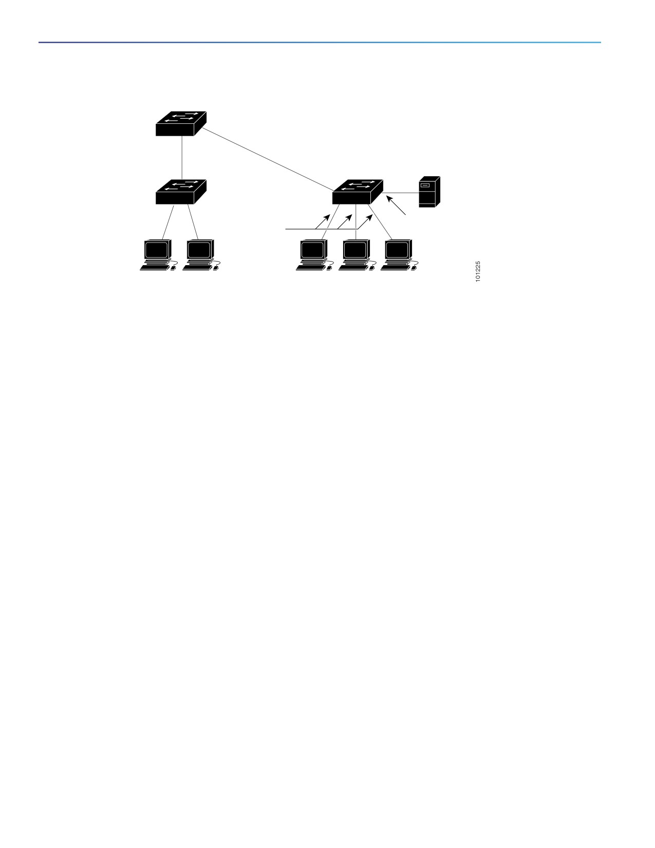
Configuring Optional Spanning-Tree Features
Information About Configuring the Optional Spanning-Tree Features
Figure 44
PortFast-Enabled Interfaces
Server
Port
Port
Fast-enabled port
Fast-enabled
ports
Workstations
Workstations
BPDU Guard
The BPDU guard feature can be globally enabled on the switch or can be enabled per port, but the feature operates with
some differences.
At the global level, you enable BPDU guard on PortFast-enabled ports by using the spanning-tree portfast bpduguard
default global configuration command. Spanning tree shuts down ports that are in a PortFast-operational state if any
BPDU is received on them. In a valid configuration, PortFast-enabled ports do not receive BPDUs. Receiving a BPDU on
a PortFast-enabled port means an invalid configuration, such as the connection of an unauthorized device, and the BPDU
guard feature puts the port in the error-disabled state. When this happens, the switch shuts down the entire port on
which the violation occurred.
To prevent the port from shutting down, you can use the errdisable detect cause bpduguard shutdown vlan global
configuration command to shut down just the offending VLAN on the port where the violation occurred.
At the interface level, you enable BPDU guard on any port by using the spanning-tree bpduguard enable interface
configuration command without also enabling the PortFast feature. When the port receives a BPDU, it is put in the
error-disabled state.
The BPDU guard feature provides a secure response to invalid configurations because you must manually put the
interface back in service. Use the BPDU guard feature in a service-provider network to prevent an access port from
participating in the spanning tree.
Enabling BPDU Guard
When you globally enable BPDU guard on ports that are Port Fast-enabled (the ports are in a Port Fast-operational state),
spanning tree continues to run on the ports. They remain up unless they receive a BPDU.
In a valid configuration, Port Fast-enabled ports do not receive BPDUs. Receiving a BPDU on a Port Fast-enabled port
means an invalid configuration, such as the connection of an unauthorized device, and the BPDU guard feature puts the
port in the error-disabled state. When this happens, the switch shuts down the entire port on which the violation
occurred.
To prevent the port from shutting down, you can use the errdisable detect cause bpduguard shutdown vlan global
configuration command to shut down just the offending VLAN on the port where the violation occurred.
The BPDU guard feature provides a secure response to invalid configurations because you must manually put the port
back in service. Use the BPDU guard feature in a service-provider network to prevent an access port from participating
in the spanning tree.
372
Configuring Optional Spanning-Tree Features
Information About Configuring the Optional Spanning-Tree Features
Caution: Configure Port Fast only on ports that connect to end stations; otherwise, an accidental topology loop
could cause a data packet loop and disrupt switch and network operation.
You also can use the spanning-tree bpduguard enable interface configuration command to enable BPDU guard on any
port without also enabling the Port Fast feature. When the port receives a BPDU, it is put it in the error-disabled state.
BPDU Filtering
The BPDU filtering feature can be globally enabled on the switch or can be enabled per interface, but the feature operates
with some differences.
At the global level, you can enable BPDU filtering on PortFast-enabled interfaces by using the spanning-tree portfast
bpdufilter default global configuration command. This command prevents interfaces that are in a PortFast-operational
state from sending or receiving BPDUs. The interfaces still send a few BPDUs at link-up before the switch begins to filter
outbound BPDUs. You should globally enable BPDU filtering on a switch so that hosts connected to these interfaces do
not receive BPDUs. If a BPDU is received on a PortFast-enabled interface, the interface loses its PortFast-operational
status, and BPDU filtering is disabled.
At the interface level, you can enable BPDU filtering on any interface by using the spanning-tree bpdufilter enable
interface configuration command without also enabling the PortFast feature. This command prevents the interface from
sending or receiving BPDUs.
Caution: Enabling BPDU filtering on an interface is the same as disabling spanning tree on it and can result in
spanning-tree loops.
You can enable the BPDU filtering feature for the entire switch or for an interface.
Enabling BPDU Filtering
When you globally enable BPDU filtering on Port Fast-enabled interfaces, it prevents interfaces that are in a Port
Fast-operational state from sending or receiving BPDUs. The interfaces still send a few BPDUs at link-up before the
switch begins to filter outbound BPDUs. You should globally enable BPDU filtering on a switch so that hosts connected
to these interfaces do not receive BPDUs. If a BPDU is received on a Port Fast-enabled interface, the interface loses its
Port Fast-operational status, and BPDU filtering is disabled.
Caution: Configure Port Fast only on interfaces that connect to end stations; otherwise, an accidental topology loop
could cause a data packet loop and disrupt switch and network operation.
You can also use the spanning-tree bpdufilter enable interface configuration command to enable BPDU filtering on any
interface without also enabling the Port Fast feature. This command prevents the interface from sending or receiving
BPDUs.
Caution: Enabling BPDU filtering on an interface is the same as disabling spanning tree on it and can result in
spanning-tree loops.
UplinkFast
Switches in hierarchical networks can be grouped into backbone switches, distribution switches, and access switches.
Figure 45 on page 374 shows a complex network where distribution switches and access switches each have at least
one redundant link that spanning tree blocks to prevent loops.
373
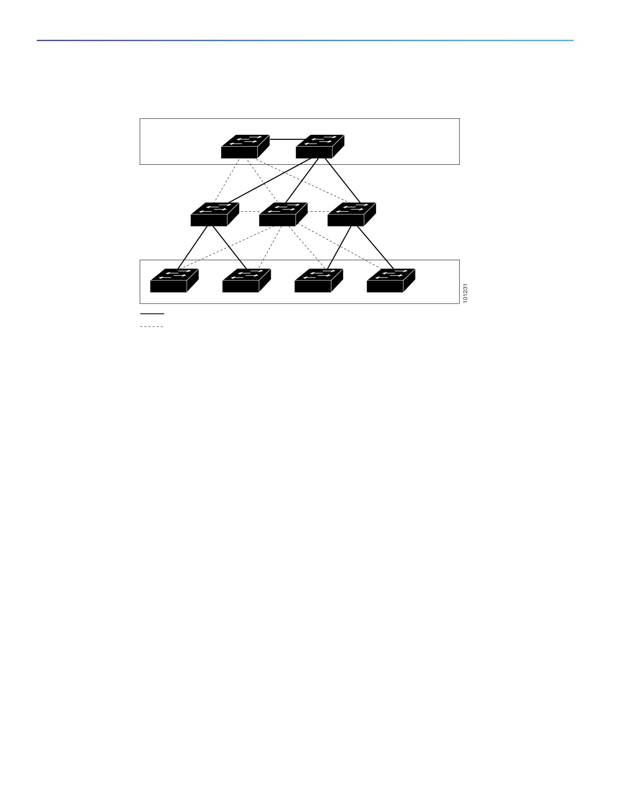
Configuring Optional Spanning-Tree Features
Information About Configuring the Optional Spanning-Tree Features
Figure 45
Switches in a Hierarchical Network
Backbone switches
Root bridge
Distribution switches
Active link
Access switches
Blocked link
If a switch loses connectivity, it begins using the alternate paths as soon as the spanning tree selects a new root port.
By enabling UplinkFast with the spanning-tree uplinkfast global configuration command, you can accelerate the choice
of a new root port when a link or switch fails or when the spanning tree reconfigures itself. The root port transitions to
the forwarding state immediately without going through the listening and learning states, as it would with the normal
spanning-tree procedures.
When the spanning tree reconfigures the new root port, other interfaces flood the network with multicast packets, one
for each address that was learned on the interface. You can limit these bursts of multicast traffic by reducing the
max-update-rate parameter (the default for this parameter is 150 packets per second). However, if you enter zero,
station-learning frames are not generated, so the spanning-tree topology converges more slowly after a loss of
connectivity.
Note: UplinkFast is most useful in wiring-closet switches at the access or edge of the network. It is not appropriate for
backbone devices. This feature might not be useful for other types of applications.
UplinkFast provides fast convergence after a direct link failure and achieves load balancing between redundant Layer 2
links using uplink groups. An uplink group is a set of Layer 2 interfaces (per VLAN), only one of which is forwarding at
any given time. Specifically, an uplink group consists of the root port (which is forwarding) and a set of blocked ports,
except for self-looping ports. The uplink group provides an alternate path in case the currently forwarding link fails.
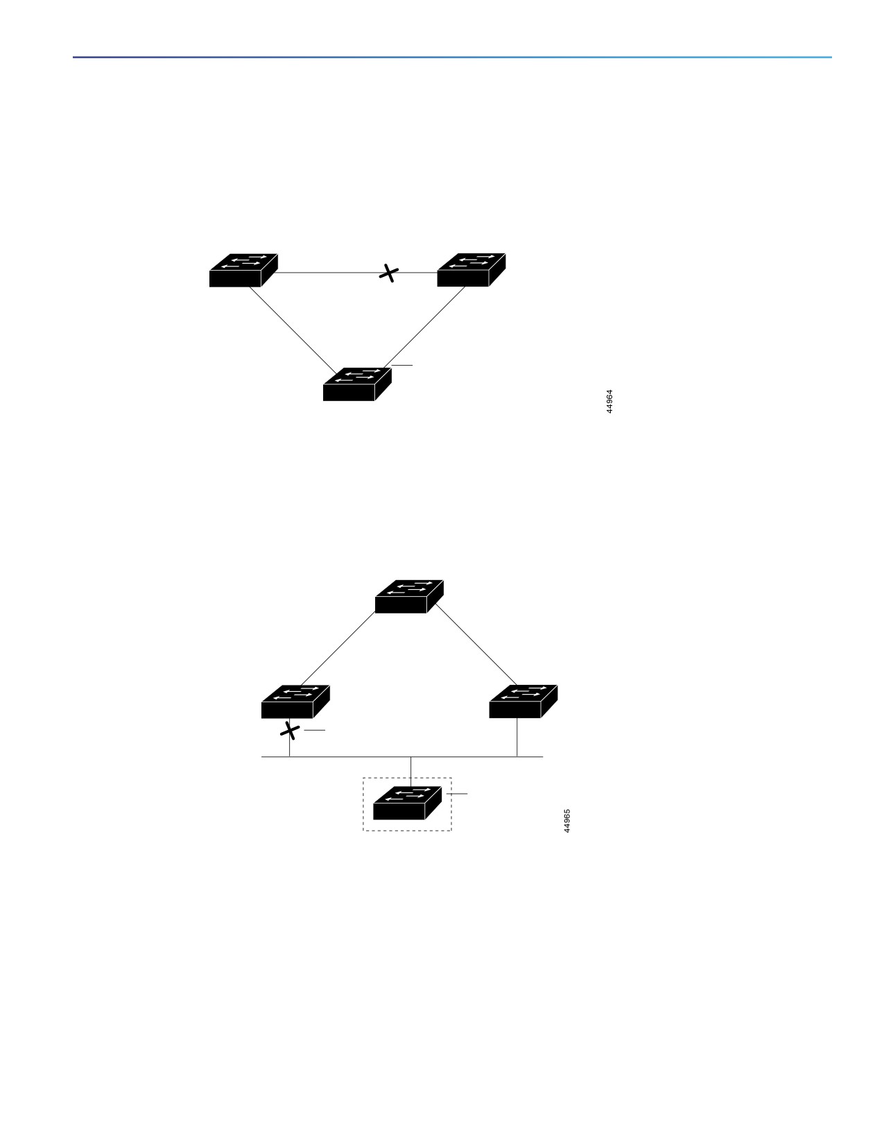
Figure 46 on page 375 shows an example topology with no link failures. Switch A, the root switch, is connected directly
to Switch B over link L1 and to Switch C over link L2. The Layer 2 interface on Switch C that is connected directly to
Switch B is in a blocking state.
374
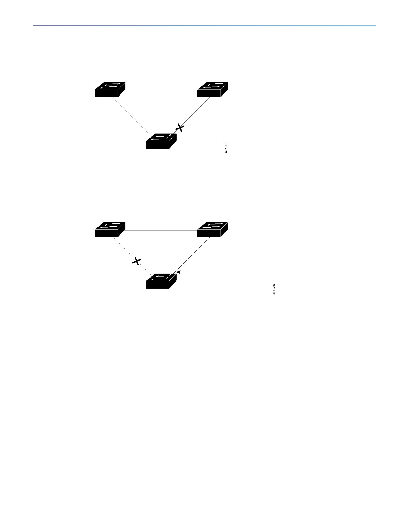
Configuring Optional Spanning-Tree Features
Information About Configuring the Optional Spanning-Tree Features
Figure 46
UplinkFast Example Before Direct Link Failure
Switch A
(Root)
Switch B
L1
L2
L3
Blocked port
Switch C
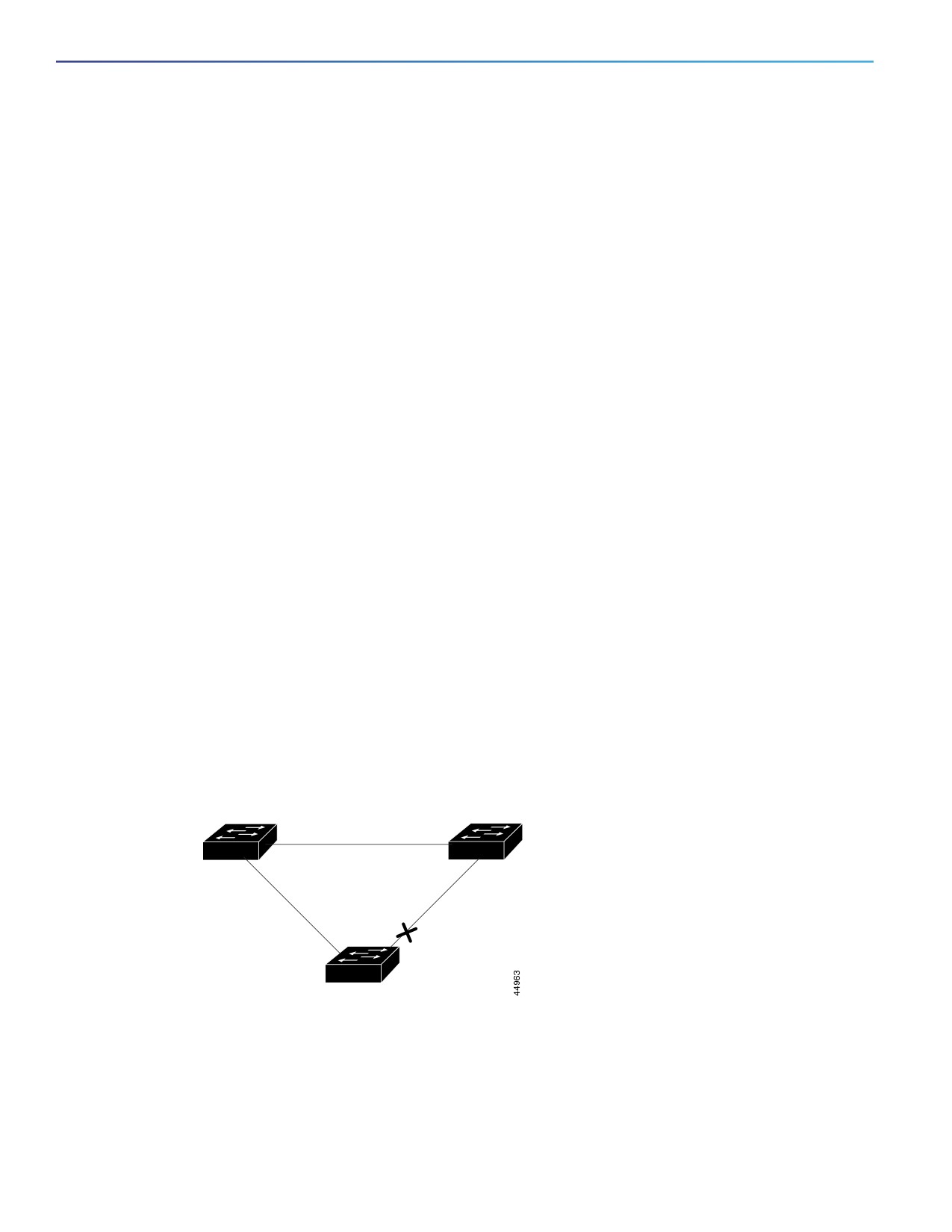
If Switch C detects a link failure on the currently active link L2 on the root port (a direct link failure), UplinkFast unblocks
the blocked interface on Switch C and transitions it to the forwarding state without going through the listening and
learning states, as shown in Figure 47 on page 375. This change takes approximately 1 to 5 seconds.
Figure 47
UplinkFast Example After Direct Link Failure
Switch A
(Root)
Switch B
L1
L2
L3
Link failure
UplinkFast transitions port
directly to forwarding state.
Switch C
Enabling UplinkFast for Use with Redundant Links
UplinkFast cannot be enabled on VLANs that have been configured with a switch priority. To enable UplinkFast on a VLAN
with switch priority configured, first restore the switch priority on the VLAN to the default value by using the no
spanning-tree vlan vlan-id priority global configuration command.
Note: When you enable UplinkFast, it affects all VLANs on the switch. You cannot configure UplinkFast on an individual
VLAN.
You can configure the UplinkFast feature for rapid PVST+ or for the MSTP, but the feature remains disabled (inactive) until
you change the spanning-tree mode to PVST+.
When UplinkFast is enabled, the switch priority of all VLANs is set to 49152. If you change the path cost to a value less
than 3000 and you enable UplinkFast or UplinkFast is already enabled, the path cost of all interfaces and VLAN trunks is
increased by 3000 (if you change the path cost to 3000 or above, the path cost is not altered). The changes to the switch
priority and the path cost reduce the chance that a switch will become the root switch.
When UplinkFast is disabled, the switch priorities of all VLANs and path costs of all interfaces are set to default values if
you did not modify them from their defaults.
375
Configuring Optional Spanning-Tree Features
Information About Configuring the Optional Spanning-Tree Features
BackboneFast
BackboneFast detects indirect failures in the core of the backbone. BackboneFast is a complementary technology to the
UplinkFast feature, which responds to failures on links directly connected to access switches. BackboneFast optimizes
the maximum-age timer, which controls the amount of time the switch stores protocol information received on an
interface. When a switch receives an inferior BPDU from the designated port of another switch, the BPDU is a signal that
the other switch might have lost its path to the root, and BackboneFast tries to find an alternate path to the root.
BackboneFast, which is enabled by using the spanning-tree backbonefast global configuration command, starts when
a root port or blocked interface on a switch receives inferior BPDUs from its designated switch. An inferior BPDU
identifies a switch that declares itself as both the root bridge and the designated switch. When a switch receives an
inferior BPDU, it means that a link to which the switch is not directly connected (an indirect link) has failed (that is, the
designated switch has lost its connection to the root switch). Under spanning-tree rules, the switch ignores inferior
BPDUs for the configured maximum aging time specified by the spanning-tree vlan vlan-id max-age global
configuration command.
The switch tries to find if it has an alternate path to the root switch. If the inferior BPDU arrives on a blocked interface,
the root port and other blocked interfaces on the switch become alternate paths to the root switch. (Self-looped ports
are not considered alternate paths to the root switch.) If the inferior BPDU arrives on the root port, all blocked interfaces
become alternate paths to the root switch. If the inferior BPDU arrives on the root port and there are no blocked
interfaces, the switch assumes that it has lost connectivity to the root switch, causes the maximum aging time on the
root port to expire, and becomes the root switch according to normal spanning-tree rules.
If the switch has alternate paths to the root switch, it uses these alternate paths to send a root link query (RLQ) request.
The switch sends the RLQ request on all alternate paths and waits for an RLQ reply from other switches in the network.
If the switch discovers that it still has an alternate path to the root, it expires the maximum aging time on the interface
that received the inferior BPDU. If all the alternate paths to the root switch indicate that the switch has lost connectivity
to the root switch, the switch expires the maximum aging time on the interface that received the RLQ reply. If one or more
alternate paths can still connect to the root switch, the switch makes all interfaces on which it received an inferior BPDU
its designated ports and moves them from the blocking state (if they were in the blocking state), through the listening
and learning states, and into the forwarding state.
Figure 48 on page 376 shows an example topology with no link failures. Switch A, the root switch, connects directly to
Switch B over link L1 and to Switch C over link L2. The Layer 2 interface on Switch C that connects directly to Switch B
is in the blocking state.
Figure 48
BackboneFast Example Before Indirect Link Failure
Switch A
(Root)
Switch B
L1
L2
L3
Blocked port
Switch C
If link L1 fails as shown in Figure 49 on page 377, Switch C cannot detect this failure because it is not connected directly
to link L1. However, because Switch B is directly connected to the root switch over L1, it detects the failure, elects itself
the root, and begins sending BPDUs to Switch C, identifying itself as the root. When Switch C receives the inferior BPDUs
from Switch B, Switch C assumes that an indirect failure has occurred. At that point, BackboneFast allows the blocked
interface on Switch C to move immediately to the listening state without waiting for the maximum aging time for the
interface to expire. BackboneFast then transitions the Layer 2 interface on Switch C to the forwarding state, providing a
376
Configuring Optional Spanning-Tree Features
Information About Configuring the Optional Spanning-Tree Features
path from Switch B to Switch A. The root-switch election takes approximately 30 seconds, twice the Forward Delay time
if the default Forward Delay time of 15 seconds is set. Figure 49 on page 377 shows how BackboneFast reconfigures
the topology to account for the failure of link L1.
Figure 49
BackboneFast Example After Indirect Link Failure
Switch A
(Root)
Switch B
L1
Link failure
L2
L3
BackboneFast changes port
through listening and learning
states to forwarding state.
Switch C
If a new switch is introduced into a shared-medium topology as shown in Figure 50 on page 377, BackboneFast is not
activated because the inferior BPDUs did not come from the recognized designated switch (Switch B). The new switch
begins sending inferior BPDUs that indicate it is the root switch. However, the other switches ignore these inferior BPDUs,
and the new switch learns that Switch B is the designated switch to Switch A, the root switch.
Figure 50
Adding a Switch in a Shared-Medium Topology
Switch A
(Root)
Switch B
Switch C
(Designated bridge)
Blocked port
Added switch
Enabling BackboneFast
You can enable BackboneFast to detect indirect link failures and to start the spanning-tree reconfiguration sooner.
Note: If you use BackboneFast, you must enable it on all switches in the network. BackboneFast is not supported on
Token Ring VLANs. This feature is supported for use with third-party switches.
377
Configuring Optional Spanning-Tree Features
Information About Configuring the Optional Spanning-Tree Features
EtherChannel Guard
You can use EtherChannel guard to detect an EtherChannel misconfiguration between the switch and a connected
device. A misconfiguration can occur if the switch interfaces are configured in an EtherChannel, but the interfaces on the
other device are not. A misconfiguration can also occur if the channel parameters are not the same at both ends of the
EtherChannel.
If the switch detects a misconfiguration on the other device, EtherChannel guard places the switch interfaces in the
error-disabled state, and displays an error message.
You can enable this feature by using the spanning-tree etherchannel guard misconfig global configuration command.
Root Guard
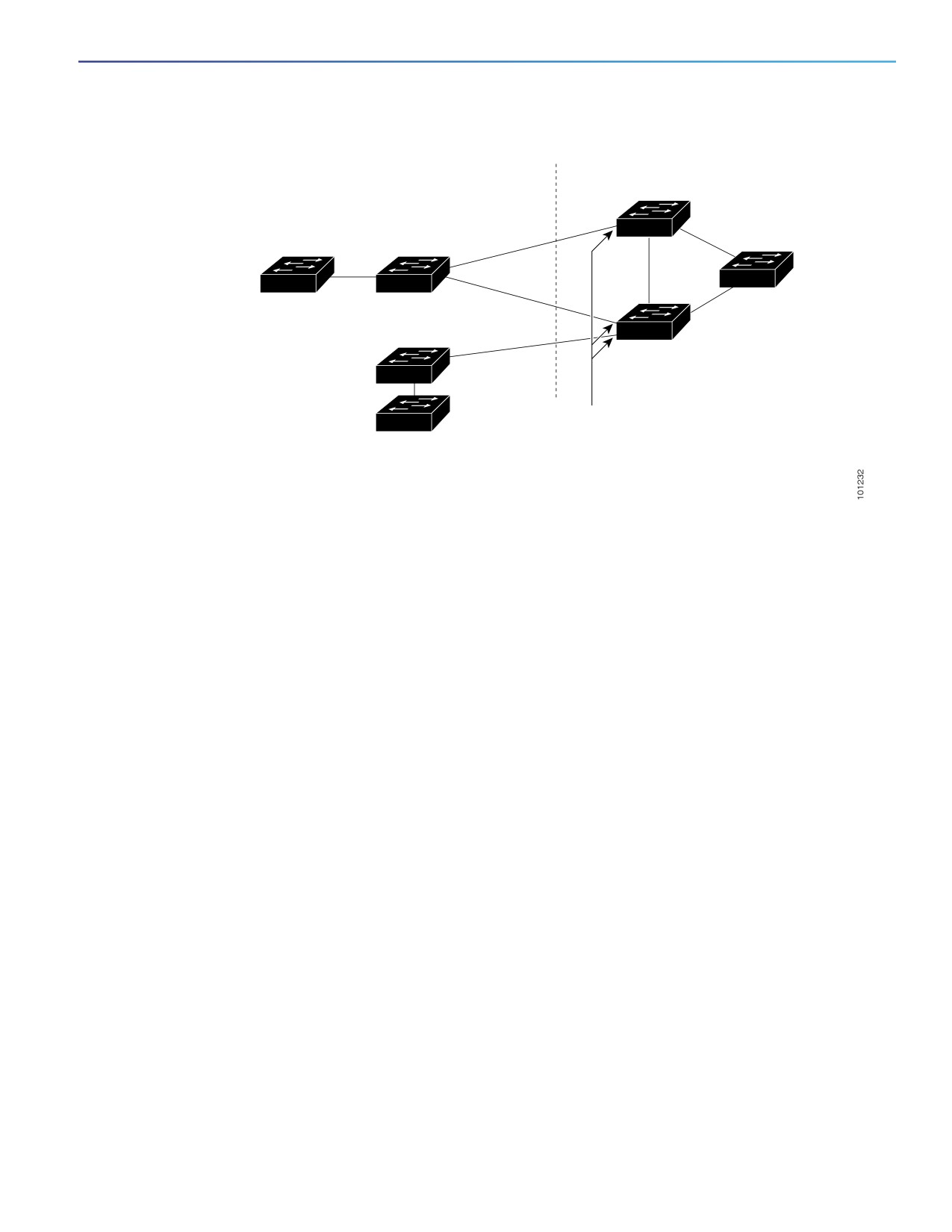
The Layer 2 network of a service provider (SP) can include many connections to switches that are not owned by the SP.
In such a topology, the spanning tree can reconfigure itself and select a customer switch as the root switch, as shown in
Figure 51 on page 379. You can avoid this situation by enabling root guard on SP switch interfaces that connect to
switches in your customer’s network. If spanning-tree calculations cause an interface in the customer network to be
selected as the root port, root guard then places the interface in the root-inconsistent (blocked) state to prevent the
customer’s switch from becoming the root switch or being in the path to the root.
If a switch outside the SP network becomes the root switch, the interface is blocked (root-inconsistent state), and
spanning tree selects a new root switch. The customer’s switch does not become the root switch and is not in the path
to the root.
If the switch is operating in multiple spanning-tree (MST) mode, root guard forces the interface to be a designated port.
If a boundary port is blocked in an internal spanning-tree (IST) instance because of root guard, the interface also is
blocked in all MST instances. A boundary port is an interface that connects to a LAN, the designated switch of which is
either an IEEE 802.1D switch or a switch with a different MST region configuration.
Root guard enabled on an interface applies to all the VLANs to which the interface belongs. VLANs can be grouped and
mapped to an MST instance.
You can enable this feature by using the spanning-tree guard root interface configuration command.
Caution: Misuse of the root guard feature can cause a loss of connectivity.
378
Configuring Optional Spanning-Tree Features
Information About Configuring the Optional Spanning-Tree Features
Figure 51
Root Guard in a Service-Provider Network
Customer network
Service-provider network
Potential
spanning-tree root without
root guard enabled
Desired
root switch
Enable the root-guard feature
on these interfaces to prevent
switches in the customer
network from becoming
the root switch or being
in the path to the root.
Enabling Root Guard
Root guard enabled on an interface applies to all the VLANs to which the interface belongs. Do not enable the root guard
on interfaces to be used by the UplinkFast feature. With UplinkFast, the backup interfaces (in the blocked state) replace
the root port in the case of a failure. However, if root guard is also enabled, all the backup interfaces used by the
UplinkFast feature are placed in the root-inconsistent state (blocked) and are prevented from reaching the forwarding
state.
Note: You cannot enable both root guard and loop guard at the same time.
Loop Guard
You can use loop guard to prevent alternate or root ports from becoming designated ports because of a failure that leads
to a unidirectional link. This feature is most effective when it is enabled on the entire switched network. Loop guard
prevents alternate and root ports from becoming designated ports, and spanning tree does not send BPDUs on root or
alternate ports.
You can enable this feature by using the spanning-tree loopguard default global configuration command.
When the switch is operating in PVST+ or rapid-PVST+ mode, loop guard prevents alternate and root ports from
becoming designated ports, and spanning tree does not send BPDUs on root or alternate ports.
When the switch is operating in MST mode, BPDUs are not sent on nonboundary ports only if the interface is blocked by
loop guard in all MST instances. On a boundary port, loop guard blocks the interface in all MST instances.
Enabling Loop Guard
You can use loop guard to prevent alternate or root ports from becoming designated ports because of a failure that leads
to a unidirectional link. This feature is most effective when it is configured on the entire switched network. Loop guard
operates only on interfaces that are considered point-to-point by the spanning tree.
Note: You cannot enable both loop guard and root guard at the same time.
379

Configuring Optional Spanning-Tree Features
How to Configure the Optional Spanning-Tree Features
Default Optional Spanning-Tree Settings
Table 45
Default Optional Spanning-Tree Settings
Feature
Default Setting
PortFast, BPDU filtering, BPDU guard
Globally disabled (unless they are individually configured per
interface).
UplinkFast
Globally disabled.
BackboneFast
Globally disabled.
EtherChannel guard
Globally enabled.
Root guard
Disabled on all interfaces.
Loop guard
Disabled on all interfaces.
How to Configure the Optional Spanning-Tree Features
Enabling Optional SPT Features
Before You Begin
Make sure that there are no loops in the network between the trunk port and the workstation or server before you
enable PortFast on a trunk port.
Use PortFast only when connecting a single end station to an access or trunk port. Enabling this feature on an
interface connected to a switch or hub could prevent spanning tree from detecting and disabling loops in your
network, which could cause broadcast storms and address-learning problems.
An interface with the PortFast feature enabled is moved directly to the spanning-tree forwarding state without
waiting for the standard forward-time delay.
You cannot enable both loop guard and root guard at the same time.
When you enable UplinkFast, it affects all VLANs on the switch. You cannot configure UplinkFast on an individual
VLAN.
If you enable the voice VLAN feature, the PortFast feature is automatically enabled. When you disable voice VLAN,
the PortFast feature is not automatically disabled.
Command
Purpose
1.
show spanning-tree active
Verifies which interfaces are alternate or root ports.
or
show spanning-tree mst
2.
configure terminal
Enters global configuration mode.
3.
spanning-tree loopguard default
Enables loop guard.
By default, loop guard is disabled.
4.
spanning-tree portfast bpduguard default
Enables BPDU guard.
By default, BPDU guard is disabled.
380

Configuring Optional Spanning-Tree Features
Maintaining and Monitoring Optional Spanning-Tree Features
Command
Purpose
5.
spanning-tree portfast bpdufilter default
Enables BPDU filtering.
By default, BPDU filtering is disabled.
6.
spanning-tree uplinkfast [max-update-rate
Enables UplinkFast.
pkts-per-second]
(Optional) pkts-per-second—The range is 0 to 32000 packets
per second; the default is 150.
If you set the rate to 0, station-learning frames are not
generated, and the spanning-tree topology converges more
slowly after a loss of connectivity.
7.
spanning-tree backbonefast
Enables BackboneFast.
8.
spanning-tree etherchannel guard misconfig
Enables EtherChannel guard.
9.
interface interface-id
Specifies an interface to configure, and enters interface
configuration mode.
10.
spanning-tree portfast [trunk]
Enables PortFast on an access port connected to a single
workstation or server. By specifying the trunk keyword, you can
enable PortFast on a trunk port.
Note: To enable PortFast on trunk ports, you must use the
spanning-tree portfast trunk interface configuration command.
The spanning-tree portfast command will not work on trunk
ports.
By default, PortFast is disabled on all interfaces.
11.
spanning-tree guard root
Enables root guard on the interface.
By default, root guard is disabled on all interfaces.
12.
end
Returns to privileged EXEC mode.
Maintaining and Monitoring Optional Spanning-Tree Features
Command
Purpose
show spanning-tree active
Displays spanning-tree information on active interfaces only.
show spanning-tree detail
Displays a detailed summary of interface information.
show spanning-tree interface interface-id
Displays spanning-tree information for the specified interface.
show spanning-tree mst interface interface-id
Displays MST information for the specified interface.
show spanning-tree summary [totals]
Displays a summary of interface states or displays the total
lines of the spanning-tree state section.
show interfaces status err-disabled
Displays which switch ports are disabled because of an
EtherChannel misconfiguration.
show etherchannel summary
Displays the EtherChannel configuration. Useful to use on the
remote device after switch ports are disabled.
[no] shutdown
Disables the interface. The no option reenables the interface.
381

Configuring Optional Spanning-Tree Features
Additional References
Additional References
The following sections provide references related to switch administration:
Related Documents
Related Topic
Document Title
Cisco IOS basic commands
Cisco IOS Configuration Fundamentals Command Reference
VLAN configuration
Configuring VLANs, page 289
Voice VLAN configuration
Configuring Voice VLAN, page 327
PVST+ and rapid PVST+ configuratio
Configuring STP, page 333
Multiple Spanning Tree Protocol configuration
Configuring MSTP, page 351
Standards
Standards
Title
No new or modified standards are supported by this
—
feature, and support for existing standards has not
been modified by this feature.
MIBs
MIBs
MIBs Link
—
To locate and download MIBs using Cisco IOS XR software, use the
Cisco MIB Locator found at the following URL and choose a platform
under the Cisco Access Products menu:
RFCs
RFCs
Title
No new or modified RFCs are supported by this
—
feature, and support for existing RFCs has not been
modified by this feature.
382
Configuring Resilient Ethernet Protocol
Information About Configuring REP
REP
Resilient Ethernet Protocol (REP) is a Cisco proprietary protocol that provides an alternative to Spanning Tree Protocol
(STP) to control network loops, handle link failures, and improve convergence time. REP controls a group of ports
connected in a segment, ensures that the segment does not create any bridging loops, and responds to link failures
within the segment. REP provides a basis for constructing more complex networks and supports VLAN load balancing.
One REP segment is a chain of ports connected to each other and configured with a segment ID. Each segment consists
of standard (non-edge) segment ports and two user-configured edge ports. A switch can have no more than two ports
that belong to the same segment, and each segment port can have only one external neighbor. A segment can go
through a shared medium, but on any link only two ports can belong to the same segment. REP is supported only on
Layer 2 trunk interfaces.
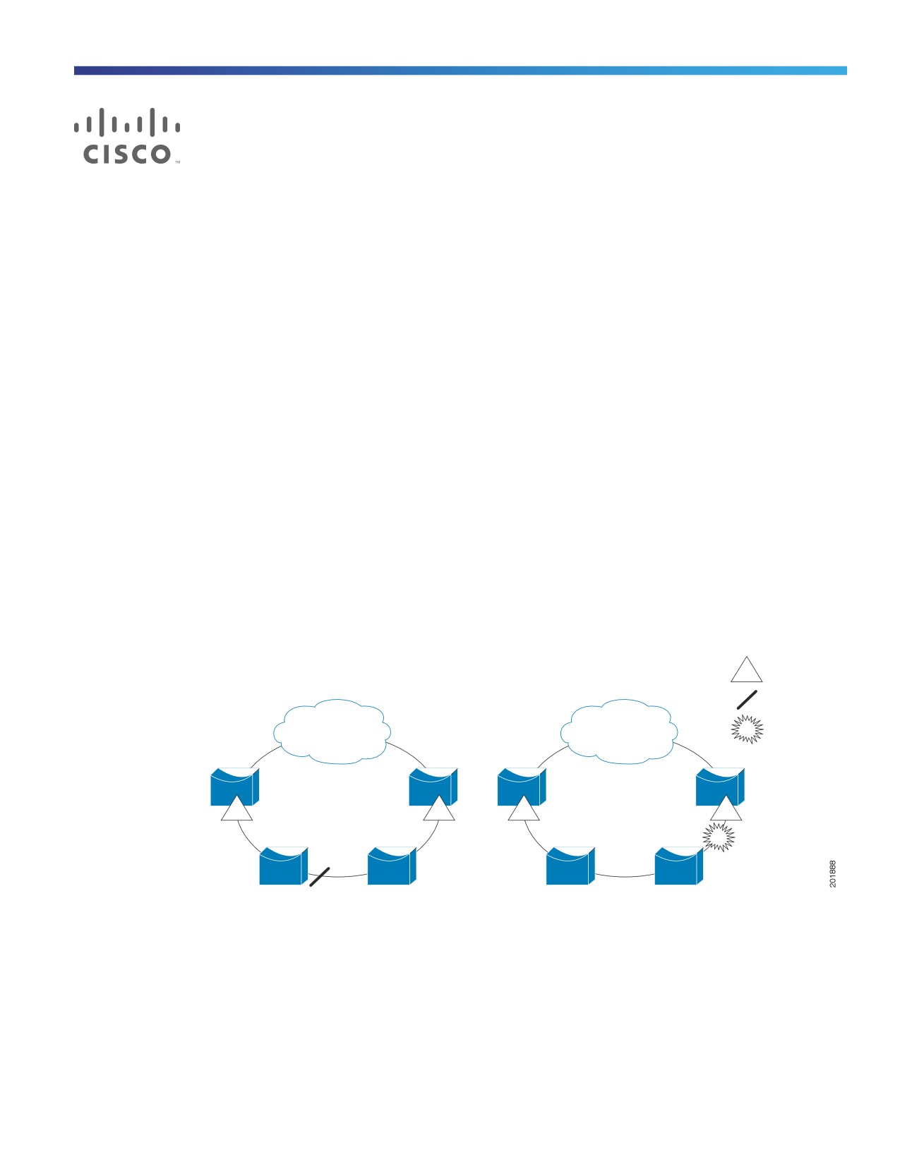
Figure 52 on page 383 shows an example of a segment consisting of six ports spread across four switches. Ports E1
and E2 are configured as edge ports. When all ports are operational (as in the segment on the left), a single port is
blocked, shown by the diagonal line. When there is a failure in the network, as shown in the diagram on the right, the
blocked port returns to the forwarding state to minimize network disruption.
Figure 52
REP Open Segments
E1
Edge port
Blocked port
Link failure
E1
E2
E1
E2
The segment shown in Figure 52 on page 383 is an open segment; there is no connectivity between the two edge ports.
The REP segment cannot cause a bridging loop and it is safe to connect the segment edges to any network. All hosts
connected to switches inside the segment have two possible connections to the rest of the network through the edge
ports, but only one connection is accessible at any time. If a failure causes a host to be unable to access its usual
gateway, REP unblocks all ports to ensure that connectivity is available through the other gateway.
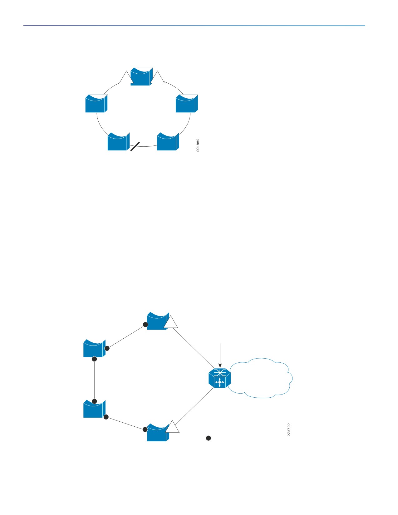
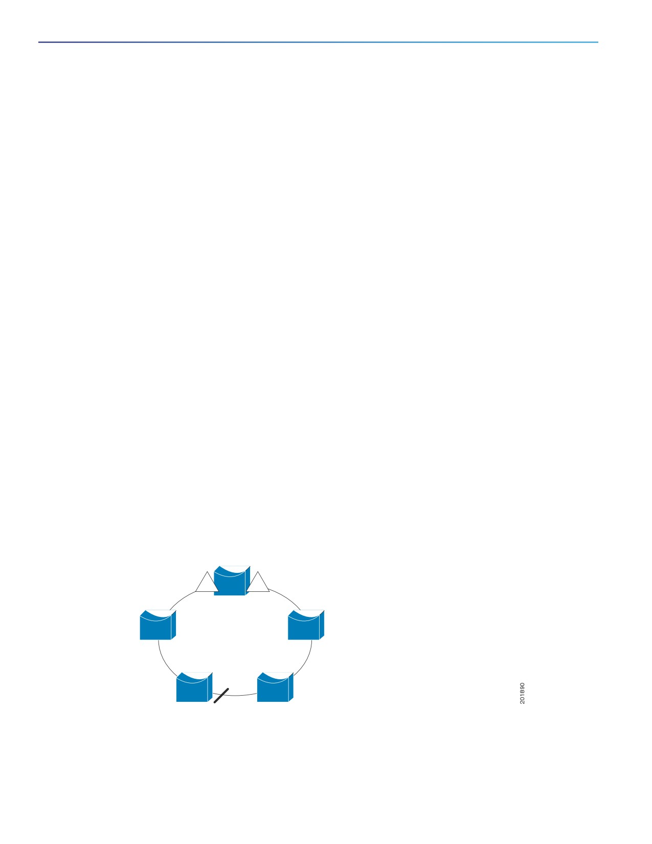
The segment shown in Figure 53 on page 384, with both edge ports located on the same switch, is a ring segment. In
this configuration, there is connectivity between the edge ports through the segment. With this configuration, you can
create a redundant connection between any two switches in the segment.
383
Configuring Resilient Ethernet Protocol
Information About Configuring REP
Figure 53
REP Ring Segment
E1
E2
REP segments have these characteristics:
If all ports in the segment are operational, one port (referred to as the alternate port) is in the blocked state for each
VLAN. If VLAN load balancing is configured, two ports in the segment control the blocked state of VLANs.
If one or more ports in a segment is not operational, causing a link failure, all ports forward traffic on all VLANs to
ensure connectivity.
In case of a link failure, the alternate ports are unblocked as quickly as possible. When the failed link comes back
up, a logically blocked port per VLAN is selected with minimal disruption to the network.
You can construct almost any type of network based on REP segments. REP also supports VLAN load-balancing,
controlled by the primary edge port but occurring at any port in the segment.
In access ring topologies, the neighboring switch might not support REP, as shown in Figure 54 on page 384. In this case,
you can configure the non-REP facing ports (E1 and E2) as edge no-neighbor ports. These ports inherit all properties of
edge ports, and you can configure them the same as any edge port, including configuring them to send STP or REP
topology change notices to the aggregation switch. In this case the STP topology change notice (TCN) that is sent is a
multiple spanning-tree (MST) STP message.
Figure 54
Edge No-Neighbor Ports
E1
REP not
supported
E1 and E2 are configured
as edge no-neighbor ports
E2
REP ports
REP has these limitations:
You must configure each segment port; an incorrect configuration can cause forwarding loops in the networks.
384
Configuring Resilient Ethernet Protocol
Information About Configuring REP
REP can manage only a single failed port within the segment; multiple port failures within the REP segment cause
loss of network connectivity.
You should configure REP only in networks with redundancy. Configuring REP in a network without redundancy
causes loss of connectivity.
Link Integrity
REP does not use an end-to-end polling mechanism between edge ports to verify link integrity. It implements local link
failure detection. The REP Link Status Layer (LSL) detects its REP-aware neighbor and establishes connectivity within
the segment. All VLANs are blocked on an interface until it detects the neighbor. After the neighbor is identified, REP
determines which neighbor port should become the alternate port and which ports should forward traffic.
Each port in a segment has a unique port ID. The port ID format is similar to that used by the spanning tree algorithm: a
port number (unique on the bridge), associated to a MAC address (unique in the network). When a segment port is
coming up, its LSL starts sending packets that include the segment ID and the port ID. The port is declared as operational
after it performs a three-way handshake with a neighbor in the same segment.
A segment port does not become operational if:
No neighbor has the same segment ID.
More than one neighbor has the same segment ID.
The neighbor does not acknowledge the local port as a peer.
Each port creates an adjacency with its immediate neighbor. Once the neighbor adjacencies are created, the ports
negotiate to determine one blocked port for the segment, the alternate port. All other ports become unblocked. By
default, REP packets are sent to a BPDU class MAC address. The packets can also be sent to the Cisco multicast address,
which is used only to send blocked port advertisement (BPA) messages when there is a failure in the segment. The
packets are dropped by devices not running REP.
REP Negotiated
Spanning Tree Protocol (STP) is enabled by default on Cisco switches. If a Cisco switch is inserted in an already running
REP ring (for example, to add a new node or replace an existing node), the new switch running STP will cause a break
in the REP ring and cannot communicate over the REP ring until it is configured to be part of the ring.
After a new switch is inserted in the ring, it is running STP, but the rest of the ring is running REP. Neither of these protocols
can recognize a loop in the ring and keep both ends of the ring in the forwarding state, causing an endless loop. To
address this problem, rep bpduleak should be configured on the new switch so that REP BPDUs are transparently
forwarded between two ring ports on the switch when REP is not configured. This function, called BPDU leaking, causes
the REP ring to converge but new devices will not be part of the ring nor be seen in or show the REP topology.
When the switch interfaces are configured with REP Negotiated, REP status is negotiated with the peers. If the peer
supports REP, it is migrated to REP. If the peer does not support REP, it is migrated to STP. The peer is migrated to REP
or STP using an Embedded Event Manager (EEM) macro.
Note: REP Negotiated works only on uplink ports.
See Configuring REP Negotiated, page 392 for information about configuring REP Negotiated.
Fast Convergence
Because REP runs on a physical link basis and not a per-VLAN basis, only one hello message is required for all VLANs,
reducing the load on the protocol. We recommend that you create VLANs consistently on all switches in a given segment
and configure the same allowed VLANs on the REP trunk ports. To avoid the delay introduced by relaying messages in
385
Configuring Resilient Ethernet Protocol
Information About Configuring REP
software, REP also allows some packets to be flooded to a regular multicast address. These messages operate at the
hardware flood layer (HFL) and are flooded to the whole network, not just the REP segment. Switches that do not belong
to the segment treat them as data traffic. You can control flooding of these messages by configuring a dedicated
administrative VLAN for the whole domain.
The estimated convergence recovery time on fiber interfaces is 50-200 ms for the local segment with 200 VLANs
configured. When REP is configured on RJ45 Gigabit copper interfaces, the convergence time is 500-750 ms.
Convergence for VLAN load balancing is 300 ms or less.
VLAN Load Balancing
One edge port in the REP segment acts as the primary edge port; the other as the secondary edge port. It is the primary
edge port that always participates in VLAN load balancing in the segment. REP VLAN balancing is achieved by blocking
some VLANs at a configured alternate port and all other VLANs at the primary edge port. When you configure VLAN load
balancing, you can specify the alternate port in one of three ways:
By entering the port ID of the interface. To identify the port ID of a port in the segment, enter the show interface rep
detail interface configuration command for the port.
By entering the neighbor offset number of a port in the segment, which identifies the downstream neighbor port of
an edge port. The neighbor offset number range is -256 to +256; a value of 0 is invalid. The primary edge port has
an offset number of 1; positive numbers above 1 identify downstream neighbors of the primary edge port. Negative
numbers indicate the secondary edge port (offset number -1) and its downstream neighbors.
Note: You configure offset numbers on the primary edge port by identifying a port’s downstream position from the
primary (or secondary) edge port. You would never enter an offset value of 1 because that is the offset number of
the primary edge port itself.
Figure 55 on page 386 shows neighbor offset numbers for a segment where E1 is the primary edge port and E2 is
the secondary edge port. The red numbers inside the ring are numbers offset from the primary edge port; the black
numbers outside of the ring show the offset numbers from the secondary edge port. Note that you can identify all
ports (except the primary edge port) by either a positive offset number (downstream position from the primary edge
port) or a negative offset number (downstream position from the secondary edge port). If E2 became the primary
edge port, its offset number would then be 1 and E1 would be -1.
By entering the preferred keyword to select the port that you previously configured as the preferred alternate port
with the rep segment segment-id preferred interface configuration command.
Figure 55
Neighbor Offset Numbers in a Segment
-1
E1 = Primary edge port
E1
E2
E2 = Secondary edge port
1
10
-2
-9
2
9
Offset numbers from the primary edge port
Offset numbers from the secondary edge
port (negative numbers)
-8
3
8
-3
4
7
-4
-7
5
6
-5
-6
When the REP segment is complete, all VLANs are blocked. When you configure VLAN load balancing, you must also
configure triggers in one of two ways:
386
Configuring Resilient Ethernet Protocol
Information About Configuring REP
Manually trigger VLAN load balancing at any time by entering the rep preempt segment segment-id privileged EXEC
command on the switch that has the primary edge port.
Configure a preempt delay time by entering the rep preempt delay seconds interface configuration command. After
a link failure and recovery, VLAN load balancing begins after the configured preemption time period elapses. Note
that the delay timer restarts if another port fails before the time has elapsed.
Note: When VLAN load balancing is configured, it does not start working until triggered by either manual intervention or
a link failure and recovery.
When VLAN load balancing is triggered, the primary edge port sends out a message to alert all interfaces in the segment
about the preemption. When the secondary port receives the message, it is reflected into the network to notify the
alternate port to block the set of VLANs specified in the message and to notify the primary edge port to block the
remaining VLANs.
You can also configure a particular port in the segment to block all VLANs. Only the primary edge port initiates VLAN load
balancing, which is not possible if the segment is not terminated by an edge port on each end. The primary edge port
determines the local VLAN load balancing configuration.
Reconfigure the primary edge port to reconfigure load balancing. When you change the load balancing configuration, the
primary edge port again waits for the rep preempt segment command or for the configured preempt delay period after
a port failure and recovery before executing the new configuration. If you change an edge port to a regular segment port,
the existing VLAN load balancing status does not change. Configuring a new edge port might cause a new topology
configuration.
Spanning Tree Interaction
REP does not interact with STP or with the FlexLink feature, but can coexist with both. A port that belongs to a segment
is removed from spanning tree control and STP BPDUs are not accepted or sent from segment ports. Therefore, STP
cannot run on a segment.
To migrate from an STP ring configuration to REP segment configuration, begin by configuring a single port in the ring
as part of the segment and continue by configuring contiguous ports to minimize the number of segments. Each segment
always contains a blocked port, so multiple segments means multiple blocked ports and a potential loss of connectivity.
When the segment has been configured in both directions up to the location of the edge ports, you then configure the
edge ports.
REP Ports
Ports in REP segments are Failed, Open, or Alternate.
A port configured as a regular segment port starts as a failed port.
After the neighbor adjacencies are determined, the port transitions to alternate port state, blocking all VLANs on the
interface. Blocked port negotiations occur and when the segment settles, one blocked port remains in the alternate
role and all other ports become open ports.
When a failure occurs in a link, all ports move to the failed state. When the alternate port receives the failure
notification, it changes to the open state, forwarding all VLANs.
A regular segment port converted to an edge port, or an edge port converted to a regular segment port, does not always
result in a topology change. If you convert an edge port into a regular segment port, VLAN load balancing is not
implemented unless it has been configured. For VLAN load balancing, you must configure two edge ports in the segment.
A segment port that is reconfigured as a spanning tree port restarts according the spanning tree configuration. By default,
this is a designated blocking port. If PortFast is configured or if STP is disabled, the port goes into the forwarding state.
387
Configuring Resilient Ethernet Protocol
REP Segments
REP Segments
A segment is a collection of ports connected one to the other in a chain and configured with a segment ID. To configure
REP segments, you configure the REP administrative VLAN (or use the default VLAN 1) and then add the ports to the
segment using interface configuration mode. You should configure two edge ports in the segment, with one of them the
primary edge port and the other by default the secondary edge port. A segment has only one primary edge port. If you
configure two ports in a segment as the primary edge port, for example, ports on different switches, the REP selects one
of them to serve as the segment primary edge port. You can also optionally configure where to send segment topology
change notices (STCNs) and VLAN load balancing.
Default REP Configuration
REP is disabled on all interfaces. When enabled, the interface is a regular segment port unless it is configured as an edge
port.
When REP is enabled, the sending of segment topology change notices (STCNs) is disabled, all VLANs are blocked, and
the administrative VLAN is VLAN 1.
When VLAN load balancing is enabled, the default is manual preemption with the delay timer disabled. If VLAN load
balancing is not configured, the default after manual preemption is to block all VLANs at the primary edge port.
REP Configuration Guidelines
Follow these guidelines when configuring REP:
We recommend that you begin by configuring one port and then configure the contiguous ports to minimize the
number of segments and the number of blocked ports.
If more than two ports in a segment fail when no external neighbors are configured, one port changes to a forwarding
state for the data path to help maintain connectivity during configuration. In the show rep interface privileged EXEC
command output, the Port Role for this port shows as Fail Logical Open; the Port Role for the other failed port shows
as Fail No Ext Neighbor. When the external neighbors for the failed ports are configured, the ports go through the
alternate port state transitions and eventually go to an open state or remain as the alternate port, based on the
alternate port election mechanism.
REP ports must be Layer 2 trunk ports.
Be careful when configuring REP through a Telnet connection. Because REP blocks all VLANs until another REP
interface sends a message to unblock it, you might lose connectivity to the switch if you enable REP in a Telnet
session that accesses the switch through the same interface.
You cannot run REP and STP or REP and Flex Links on the same segment or interface.
If you connect an STP network to the REP segment, be sure that the connection is at the segment edge. An STP
connection that is not at the edge could cause a bridging loop because STP does not run on REP segments. All STP
BPDUs are dropped at REP interfaces.
You must configure all trunk ports in the segment with the same set of allowed VLANs, or a misconfiguration occurs.
REP ports follow these rules:
— There is no limit to the number of REP ports on a switch; however, only two ports on a switch can belong to the
same REP segment.
— If only one port on a switch is configured in a segment, the port should be an edge port.
— If two ports on a switch belong to the same segment, they must be both edge ports, both regular segment ports,
or one regular port and one edge no-neighbor port. An edge port and regular segment port on a switch cannot
belong to the same segment.
388
Configuring Resilient Ethernet Protocol
REP Segments
— If two ports on a switch belong to the same segment and one is configured as an edge port and one as a regular
segment port (a misconfiguration), the edge port is treated as a regular segment port.
REP interfaces come up in a blocked state and remains in a blocked state until notified that it is safe to unblock. You
need to be aware of this to avoid sudden connection losses.
REP sends all LSL PDUs in untagged frames on the native VLAN. The BPA message sent to the Cisco multicast
address is sent on the administration VLAN, which is VLAN 1 by default.
You can configure how long a REP interface remains up without receiving a hello from a neighbor. You can use the
rep lsl-age-timer value interface configuration command to set the time from 120 ms to 10000 ms. The LSL hello
timer is then set to the age-timer value divided by 3. In normal operation, three LSL hellos are sent before the age
timer on the peer switch expires and checks for hello messages.
— In Cisco IOS Release 12.2(52)SE, the LSL age-timer range changed from 3000 to 10000 ms in 500-ms
increments to 120 to 10000 ms in 40-ms increments. If the REP neighbor device is not running Cisco IOS release
12.2(52)SE or later, do not configure a timer value less than 3000 ms. Configuring a value less than 3000 ms
causes the port to shut down because the neighbor switch does not respond within the requested time period.
— EtherChannel port channel interfaces do not support LSL age-timer values less than 1000 ms. If you try to
configure a value less than 1000 ms on a port channel, you receive an error message and the command is
rejected.
When configuring the REP LSL age timer, make sure that both ends of the link have the same time value configured.
Configuring different values on ports at each end of the link results in a REP link flap.
REP ports cannot be configured as one of these port types:
— SPAN destination port
— Tunnel port
— Access port
REP is supported on EtherChannels, but not on an individual port that belongs to an EtherChannel.
There is a maximum of 64 REP segments per switch.
REP Negotiated can be configured only on the first two uplink ports of the switch:
— IE3000 and IE4000—GigabitEthernet 1/1 and GigabitEthernet 1/2
— IE4010 and IE5000 (without 10G ports)—GigabitEthernet 1/25 and GigabitEthernet 1/26
— IE5000 with 10G ports—TenGigabitEthernet 1/25 and TenGigabitEthernet 1/26
REP Administrative VLAN
To avoid the delay introduced by relaying messages in software for link-failure or VLAN-blocking notification during load
balancing, REP floods packets at the hardware flood layer (HFL) to a regular multicast address. These messages are
flooded to the whole network, not just the REP segment. You can control flooding of these messages by configuring an
administrative VLAN for the whole domain.
Follow these guidelines when configuring the REP administrative VLAN:
If you do not configure an administrative VLAN, the default is VLAN 1.
There can be only one administrative VLAN on a switch and on a segment. However, this is not enforced by software.
The administrative VLAN cannot be the RSPAN VLAN.
389

Configuring Resilient Ethernet Protocol
How to Configure REP
How to Configure REP
Configuring the REP Administrative VLAN
Command
Purpose
1.
configure terminal
Enters global configuration mode.
2.
rep admin vlan vlan-id
Specifies the administrative VLAN. The range is 2 to
4096. The default is VLAN 1. To set the admin VLAN to 1,
enter the no rep admin vlan global configuration
command.
3.
end
Returns to privileged EXEC mode.
Configuring REP Interfaces
Before You Begin
For REP operation, you need to enable it on each segment interface and identify the segment ID. This step is required
and must be done before other REP configuration. You must also configure a primary and secondary edge port on each
segment. All other steps are optional.
Command
Purpose
1.
configure terminal
Enters global configuration mode.
2.
interface interface-id
Specifies the interface, and enters interface configuration mode. The
interface can be a physical Layer 2 interface or a port channel
(logical interface). The port-channel range is 1 to 10.
3.
switchport mode trunk
Configures the interface as a Layer 2 trunk port.
390

Configuring Resilient Ethernet Protocol
How to Configure REP
Command
Purpose
4.
rep segment segment-id [edge
Enables REP on the interface, and identifies a segment number. The
[no-neighbor] [primary]] [preferred]
segment ID range is from 1 to 1024. These optional keywords are
available:
Note: You must configure two edge ports, including one primary
edge port for each segment.
edge—Configures the port as an edge port. Entering edge
without the primary keyword configures the port as the
secondary edge port. Each segment has only two edge ports.
(Optional) primary— Configures the port as the primary edge
port, the port on which you can configure VLAN load balancing.
(Optional) no-neighbor—Configures a port with no external REP
neighbors as an edge port. The port inherits all properties of
edge ports, and you can configure them the same as any edge
port.
Note: Although each segment can have only one primary edge port,
if you configure edge ports on two different switches and enter the
primary keyword on both switches, the configuration is allowed.
However, REP selects only one of these ports as the segment
primary edge port. You can identify the primary edge port for a
segment by entering the show rep topology privileged EXEC
command.
(Optional) preferred—Indicates that the port is the preferred
alternate port or the preferred port for VLAN load balancing.
Note: Configuring a port as preferred does not guarantee that it
becomes the alternate port; it merely gives it a slight edge among
equal contenders. The alternate port is usually a previously failed
port.
5.
rep stcn {interface interface-id | segment
(Optional) Configures the edge port to send segment topology
id-list | stp}
change notices (STCNs).
interface interface-id—Designates a physical interface or port
channel to receive STCNs.
segment id-list—Identifies one or more segments to receive
STCNs. The range is 1 to 1024.
stp—Sends STCNs to STP networks.
391

Configuring Resilient Ethernet Protocol
How to Configure REP
Command
Purpose
6.
rep block port {id port-id | neighbor_offset |
(Optional) Configures VLAN load balancing on the primary edge port,
preferred} vlan {vlan-list | all}
identify the REP alternate port in one of three ways, and configure the
VLANs to be blocked on the alternate port.
id port-id—Identifies the alternate port by port ID. The port ID is
automatically generated for each port in the segment. You can
view interface port IDs by entering the show interface
interface-id rep [detail] privileged EXEC command.
neighbor_offset number—Identifies the alternate port as a
downstream neighbor from an edge port. The range is from
-256 to 256, with negative numbers indicating the downstream
neighbor from the secondary edge port. A value of 0 is invalid.
Enters -1 to identify the secondary edge port as the alternate
port. See Figure 55 on page 386 for an example of neighbor
offset numbering.
Note: Because you enter this command at the primary edge port
(offset number 1), you would never enter an offset value of 1 to
identify an alternate port.
preferred—Selects the regular segment port previously
identified as the preferred alternate port for VLAN load
balancing.
vlan vlan-list—Blocks one VLAN or a range of VLANs.
vlan all—Blocks all VLANs.
Note: Enter this command only on the REP primary edge port.
7.
rep preempt delay seconds
(Optional) You must enter this command and configure a preempt
time delay if you want VLAN load balancing to automatically trigger
after a link failure and recovery. The time delay range is 15 to 300
seconds. The default is manual preemption with no time delay.
Note: Enter this command only on the REP primary edge port.
8.
rep lsl-age-timer value
(Optional) Configures a time (in milliseconds) for which the REP
interface remains up without receiving a hello from a neighbor.
The range is from 120 to 10000 ms in 40-ms increments. The default
is 5000 ms (5 seconds).
Note: If the neighbor device is not running Cisco IOS Release
12.2(52)SE or later, it only accepts values from 3000 to 10000 ms in
500-ms intervals. EtherChannel port channel interfaces do not
support LSL age-timer values less than 1000 ms.
9.
end
Returns to privileged EXEC mode.
Configuring REP Negotiated
Use the following procedure to configure REP Negotiated in a REP network where a new switch is being inserted into the
existing REP ring topology. The adjacent switches to this newly inserted switch are referred to as peer switches.
1. On the new switch, configure rep bpduleak in global configuration mode:
rep bpduleak
!
392
Configuring Resilient Ethernet Protocol
How to Configure REP
2.
Configure the EEM macros on the new switch as shown in the following example. This example assumes that the
peer switches are configured with REP Segment 777 and the newly inserted switch has uplink ports GigabitEthernet
1/1 and GigabitEthernet 1/2.
macro auto execute CISCO_REP_NEG_EVENT {
config terminal
no rep bpduleak
interface GigabitEthernet 1/1
switchport mode trunk
no rep negotiated
rep segment 777
interface GigabitEthernet 1/2
switchport mode trunk
no rep negotiated
rep segment 777
exit
}
macro auto execute CISCO_REP_NONNEG_EVENT {
config terminal
no rep bpduleak
interface GigabitEthernet 1/1
no rep negotiated
interface GigabitEthernet 1/2
no rep negotiated
}
3.
Insert the new switch into the existing REP Ring topology.
Note: The newly inserted switch still does not have any REP Segment configurations.
4.
Check the output of show rep topology on the peer switches.
The output should show that rep bpduleak is in effect. The REP segment remains intact, but the newly inserted
switch is not reflected in the topology. This indicates that the newly inserted switch is transparently forwarding the
REP traffic between its uplink ports.
5.
Configure rep negotiated on both the uplink interfaces of the newly inserted switch.
Example:
interface range GigabitEthernet 1/1-2
rep negotiated
!
6.
Use the show rep negotiated command on the newly inserted switch to verify the status.
Example:
Switch2 #show rep negotiated
REP negotiation status : Fail
Interface1: GigabitEthernet1/1
Status : enabled
Rx State : fail, Segment-ID: 0
Interface2: GigabitEthernet1/2
Status : enabled
Rx State : fail, Segment-ID: 0
393
Configuring Resilient Ethernet Protocol
How to Configure REP
7. Configure rep negotiated on the connected uplink interfaces of both the peer switches and wait for the REP
Negotiation to complete. The following console log message on the newly inserted switch indicates that an EEM
event has been triggered by REP Negotiation.
May 22 22:54:41.087: REP negotiated event generated, executed CISCO_REP_NEG for Segment 777
8. Use the show rep negotiated command on the newly inserted switch to verify the status.
Switch2#show rep negotiated
REP negotiation status : Success
Interface1: GigabitEthernet1/1
Status : disabled
Interface2: GigabitEthernet1/2
Status : disabled
REP is configured automatically in the newly inserted switch and it also appears in the show rep topology output on
all the switches in the REP Ring.
REP Segment ID Validation
When inserting or replacing a REP node in a ring, you need to know the REP Segment-ID in advance. When operating
multiple rings, this information can be difficult to obtain.
The REP negotiated feature exchanges REP information over a CDP TLV. The same CDP TLV is extended to learn the REP
Segment-ID of the peer REP node. The REP node learns the Segment-ID and maintains it on interfaces until the link goes
down. The ring must be initially configured with a static REP Segment-ID from the edge, but the rest of the REP ring can
implement REP Segment-ID auto-discovery to facilitate deployment and automation.
To configure REP Segment ID Validation:
1. On the new switch, configure rep bpduleak in global configuration mode:
rep bpduleak
!
2. Configure a macro on the new switch, as shown in the following example. In this example, the uplink ports are
GigabitEthernet 1/1/ and GigabitEthernet 1/2.
macro auto execute CISCO_REP_NEG_EVENT {
config terminal
no rep bpduleak
interface GigabitEthernet 1/1
switchport mode trunk
no rep negotiated
rep segment $LIMIT
interface GigabitEthernet 1/2
switchport mode trunk
no rep negotiated
rep segment $LIMIT
exit
}
3. Insert the new switch into the existing REP Ring topology.
Note: The newly inserted switch still does not have any REP Segment configurations.
4. Check the output of show rep topology on the peer switches.
394
Configuring Resilient Ethernet Protocol
How to Configure REP
The output should show that rep bpduleak is in effect. The REP segment remains intact, but the newly inserted
switch is not reflected in the topology. This indicates that the newly inserted switch is transparently forwarding the
REP traffic between its uplink ports.
5.
Configure rep negotiated on both the uplink interfaces of the newly inserted switch.
Example:
interface range GigabitEthernet 1/1-2
rep negotiated
!
6.
Use the show rep negotiated command on the newly inserted switch to verify the status.
Example:
Switch2 #show rep negotiated
REP negotiation status : Fail
Interface1: GigabitEthernet1/1
Status : enabled
Rx State : fail, Segment-ID: 0
Interface2: GigabitEthernet1/2
Status : enabled
Rx State : fail, Segment-ID: 0
7.
Configure rep negotiated on the connected uplink interfaces of both the peer switches and wait for the REP
Negotiation to complete. The following console log message on the newly inserted switch indicates that an EEM
event has been triggered by REP Negotiation.
May 22 22:54:41.087: REP negotiated event generated, executed CISCO_REP_NEG for Segment 777
8.
Use the show rep negotiated command on the newly inserted switch to verify the status.
Switch2#show rep negotiated
REP negotiation status : Success
Interface1: GigabitEthernet1/1
Status : disabled
Interface2: GigabitEthernet1/2
Status : disabled
REP is configured automatically in the newly inserted switch and it also appears in the show rep topology output on
all the switches in the REP Ring.
Setting Manual Preemption for VLAN Load Balancing
Before You Begin
If you do not enter the rep preempt delay seconds interface configuration command on the primary edge port to
configure a preemption time delay, the default is to manually trigger VLAN load balancing on the segment. Be sure that
all other segment configuration has been completed before manually preempting VLAN load balancing. When you enter
the rep preempt segment segment-id command, a confirmation message appears before the command is executed
because preemption can cause network disruption.
395