Cisco Industrial Ethernet 4000, 4010 and 5000 Switch Software. Configuration Guide (2022) - page 14
Configuring STP
Information About Configuring STP
Learning—The interface prepares to participate in frame forwarding.
Forwarding—The interface forwards frames.
Disabled—The interface is not participating in spanning tree because of a shutdown port, no link on the port, or no
spanning-tree instance running on the port.
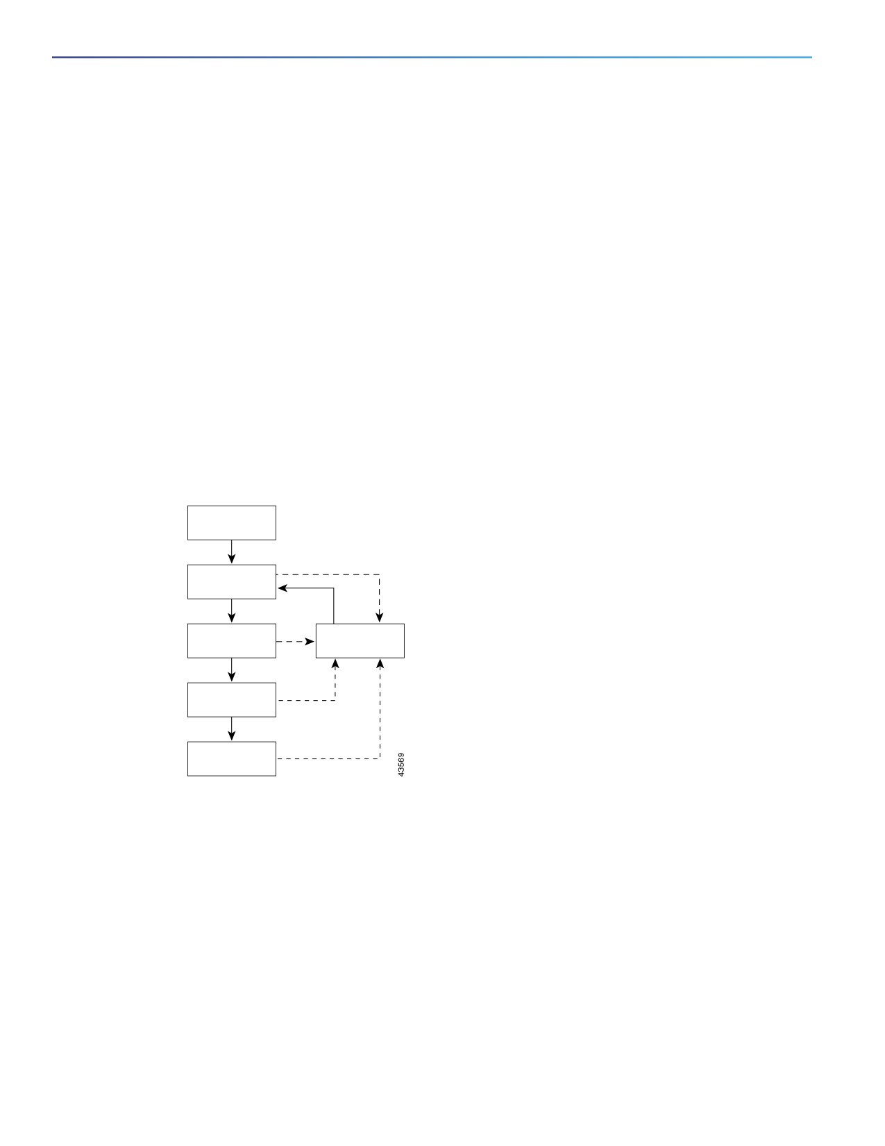
An interface moves through these states:
From initialization to blocking
From blocking to listening or to disabled
From listening to learning or to disabled
From learning to forwarding or to disabled
From forwarding to disabled
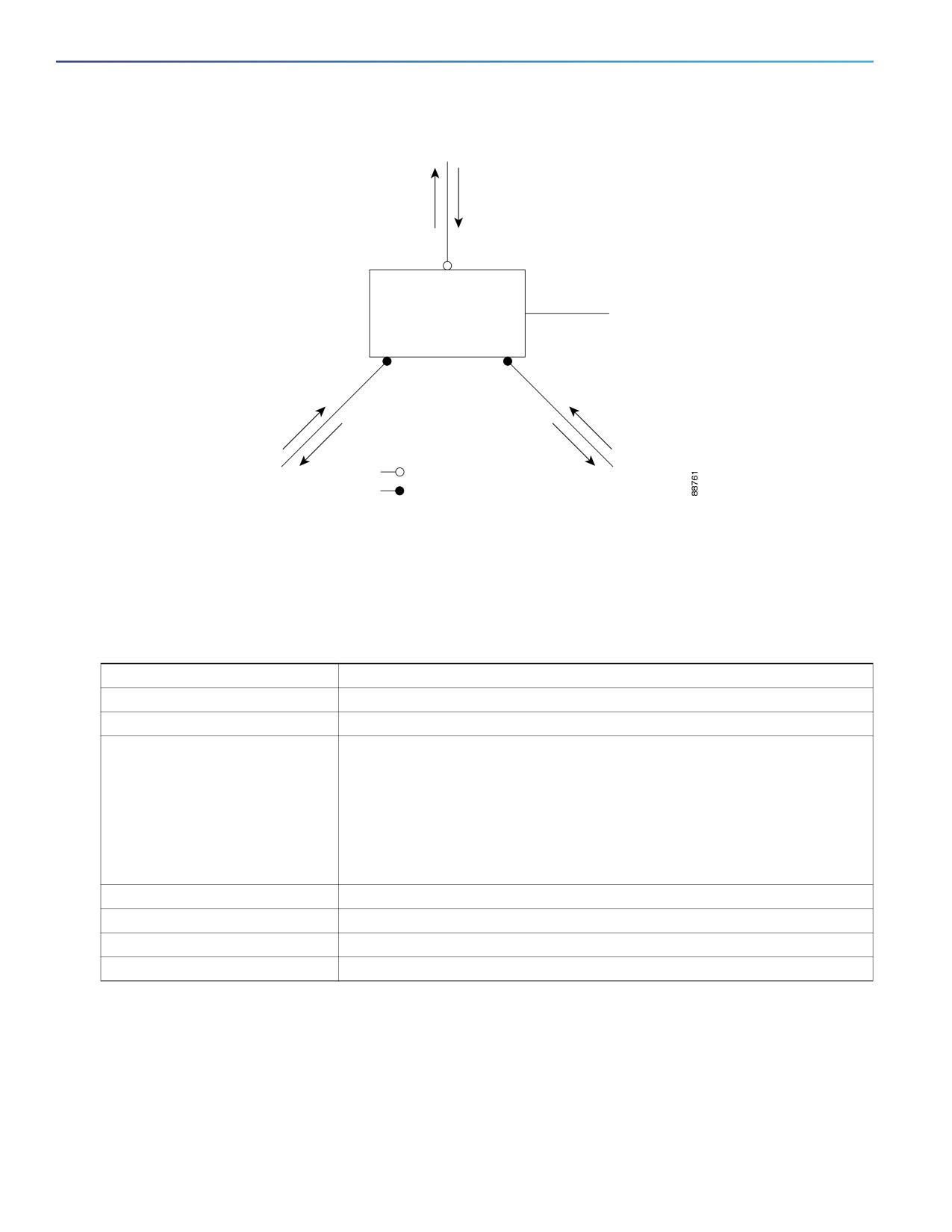
Figure 36 on page 336 illustrates how an interface moves through the states.
Figure 36
Spanning-Tree Interface States
Power-on
initialization
Blocking
state
Listening
Disabled
state
state
Learning
state
Forwarding
state
When you power up the switch, spanning tree is enabled by default, and every interface in the switch, VLAN, or network
goes through the blocking state and the transitory states of listening and learning. Spanning tree stabilizes each interface
at the forwarding or blocking state.
When the spanning-tree algorithm places a Layer 2 interface in the forwarding state, this process occurs:
1. The interface is in the listening state while spanning tree waits for protocol information to move the interface to the
blocking state.
2. While spanning tree waits the forward-delay timer to expire, it moves the interface to the learning state and resets
the forward-delay timer.
3. In the learning state, the interface continues to block frame forwarding as the switch learns end-station location
information for the forwarding database.
336
Configuring STP
Information About Configuring STP
4. When the forward-delay timer expires, spanning tree moves the interface to the forwarding state, where both
learning and frame forwarding are enabled.
Blocking State
A Layer 2 interface in the blocking state does not participate in frame forwarding. After initialization, a BPDU is sent to
each switch interface. A switch initially functions as the root until it exchanges BPDUs with other switches. This exchange
establishes which switch in the network is the root or root switch. If there is only one switch in the network, no exchange
occurs, the forward-delay timer expires, and the interface moves to the listening state. An interface always enters the
blocking state after switch initialization.
An interface in the blocking state performs these functions:
Discards frames received on the interface
Discards frames switched from another interface for forwarding
Does not learn addresses
Receives BPDUs
Listening State
The listening state is the first state a Layer 2 interface enters after the blocking state. The interface enters this state when
the spanning tree decides that the interface should participate in frame forwarding.
An interface in the listening state performs these functions:
Discards frames received on the interface
Discards frames switched from another interface for forwarding
Does not learn addresses
Receives BPDUs
Learning State
A Layer 2 interface in the learning state prepares to participate in frame forwarding. The interface enters the learning
state from the listening state.
An interface in the learning state performs these functions:
Discards frames received on the interface
Discards frames switched from another interface for forwarding
Learns addresses
Receives BPDUs
Forwarding State
A Layer 2 interface in the forwarding state forwards frames. The interface enters the forwarding state from the learning
state.
An interface in the forwarding state performs these functions:
Receives and forwards frames received on the interface
337
Configuring STP
Information About Configuring STP
Forwards frames switched from another interface
Learns addresses
Receives BPDUs
Disabled State
A Layer 2 interface in the disabled state does not participate in frame forwarding or in the spanning tree. An interface in
the disabled state is nonoperational.
A disabled interface performs these functions:
Discards frames received on the interface
Discards frames switched from another interface for forwarding
Does not learn addresses
Does not receive BPDUs
How a Switch or Port Becomes the Root Switch or Root Port
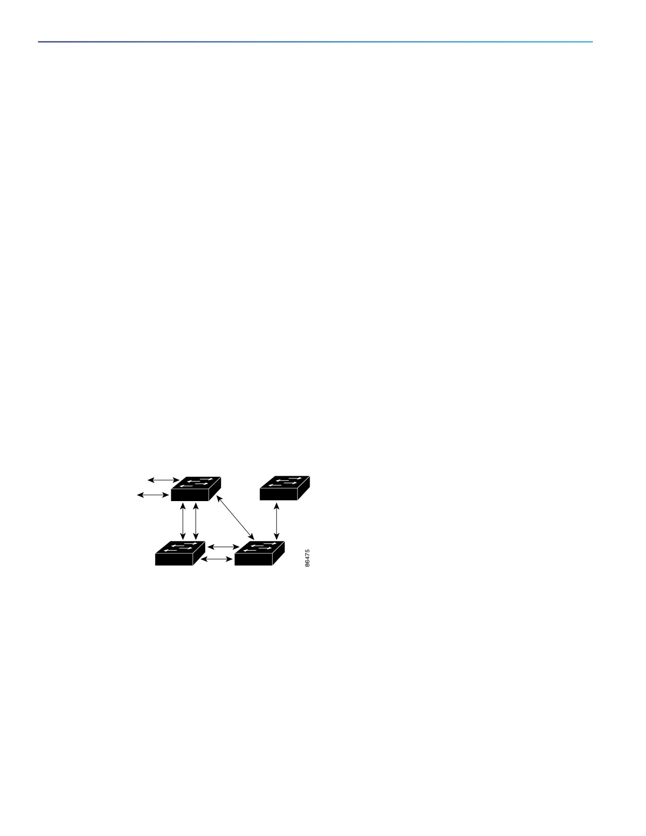
If all switches in a network are enabled with default spanning-tree settings, the switch with the lowest MAC address
becomes the root switch. In Figure 37 on page 338, Switch A is elected as the root switch because the switch priority
of all the switches is set to the default (32768) and Switch A has the lowest MAC address. However, because of traffic
patterns, number of forwarding interfaces, or link types, Switch A might not be the ideal root switch. By increasing the
priority (lowering the numerical value) of the ideal switch so that it becomes the root switch, you force a spanning-tree
recalculation to form a new topology with the ideal switch as the root.
Figure 37
Spanning-Tree Topology
DP
DP
A
DP
D
DP
RP
RP
RP
DP
B
C
RP = Root Port
DP = Designated Port
When the spanning-tree topology is calculated based on default parameters, the path between source and destination
end stations in a switched network might not be ideal. For instance, connecting higher-speed links to an interface that
has a higher number than the root port can cause a root-port change. The goal is to make the fastest link the root port.
For example, assume that one port on Switch B is a Gigabit Ethernet link and that another port on Switch B (a 10/100
link) is the root port. Network traffic might be more efficient over the Gigabit Ethernet link. By changing the spanning-tree
port priority on the Gigabit Ethernet port to a higher priority (lower numerical value) than the root port, the Gigabit Ethernet
port becomes the new root port.
338
Configuring STP
Information About Configuring STP
Spanning Tree and Redundant Connectivity
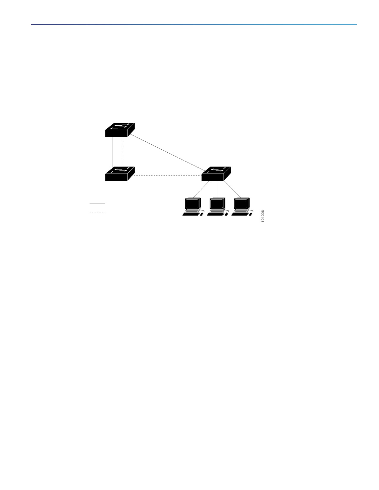
You can create a redundant backbone with spanning tree by connecting two switch interfaces to another device or to
two different devices, as shown in Figure 38 on page 339. Spanning tree automatically disables one interface but
enables it if the other one fails. If one link is high-speed and the other is low-speed, the low-speed link is always
disabled. If the speeds are the same, the port priority and port ID are added together, and spanning tree disables the link
with the lowest value.
Figure 38
Spanning Tree and Redundant Connectivity
Active link
Blocked link
Workstations
You can also create redundant links between switches by using EtherChannel groups. For more information, see
Configuring EtherChannels, page 1069
Spanning-Tree Address Management
IEEE 802.1D specifies 17 multicast addresses, ranging from 0x00180C2000000 to 0x0180C2000010, to be used by
different bridge protocols. These addresses are static addresses that cannot be removed.
Regardless of the spanning-tree state, each switch receives but does not forward packets destined for addresses
between 0x0180C2000000 and 0x0180C200000F.
If spanning tree is enabled, the CPU on the switch receives packets destined for 0x0180C2000000 and
0x0180C2000010. If spanning tree is disabled, the switch forwards those packets as unknown multicast addresses.
Accelerated Aging to Retain Connectivity
The default for aging dynamic addresses is 5 minutes, the default setting of the mac address-table aging-time global
configuration command. However, a spanning-tree reconfiguration can cause many station locations to change. Because
these stations could be unreachable for 5 minutes or more during a reconfiguration, the address-aging time is
accelerated so that station addresses can be dropped from the address table and then relearned. The accelerated aging
is the same as the forward-delay parameter value (spanning-tree vlan vlan-id forward-time seconds global
configuration command) when the spanning tree reconfigures.
Because each VLAN is a separate spanning-tree instance, the switch accelerates aging on a per-VLAN basis. A
spanning-tree reconfiguration on one VLAN can cause the dynamic addresses learned on that VLAN to be subject to
accelerated aging. Dynamic addresses on other VLANs can be unaffected and remain subject to the aging interval
entered for the switch.
339
Configuring STP
Information About Configuring STP
Spanning-Tree Modes and Protocols
The switch supports these spanning-tree modes and protocols:
PVST+—This spanning-tree mode is based on the IEEE 802.1D standard and Cisco proprietary extensions. It is the
default spanning-tree mode used on all Ethernet port-based VLANs. The PVST+ runs on each VLAN on the switch
up to the maximum supported, ensuring that each has a loop-free path through the network.
The PVST+ provides Layer 2 load balancing for the VLAN on which it runs. You can create different logical topologies
by using the VLANs on your network to ensure that all of your links are used but that no one link is oversubscribed.
Each instance of PVST+ on a VLAN has a single root switch. This root switch propagates the spanning-tree
information associated with that VLAN to all other switches in the network. Because each switch has the same
information about the network, this process ensures that the network topology is maintained.
Rapid PVST+—This spanning-tree mode is the same as PVST+ except that is uses a rapid convergence based on the
IEEE 802.1w standard. To provide rapid convergence, the rapid PVST+ immediately deletes dynamically learned
MAC address entries on a per-port basis upon receiving a topology change. By contrast, PVST+ uses a short aging
time for dynamically learned MAC address entries.
The rapid PVST+ uses the same configuration as PVST+ (except where noted), and the switch needs only minimal
extra configuration. The benefit of rapid PVST+ is that you can migrate a large PVST+ install base to rapid PVST+
without having to learn the complexities of the MSTP configuration and without having to reprovision your network.
In rapid-PVST+ mode, each VLAN runs its own spanning-tree instance up to the maximum supported.
MSTP—This spanning-tree mode is based on the IEEE 802.1s standard. You can map multiple VLANs to the same
spanning-tree instance, which reduces the number of spanning-tree instances required to support a large number
of VLANs. The MSTP runs on top of the RSTP (based on IEEE 802.1w), which provides for rapid convergence of the
spanning tree by eliminating the forward delay and by quickly transitioning root ports and designated ports to the
forwarding state. You cannot run MSTP without RSTP.
The most common initial deployment of MSTP is in the backbone and distribution layers of a Layer 2 switched
network. For more information, see Configuring MSTP, page 351
For information about the number of supported spanning-tree instances, see the next section.
Supported Spanning-Tree Instances
In PVST+ or rapid-PVST+ mode, the switch supports up to 128 spanning-tree instances.
In MSTP mode, the switch supports up to 65 MST instances. The number of VLANs that can be mapped to a particular
MST instance is unlimited.
For information about how spanning tree interoperates with the VLAN Trunking Protocol (VTP), see Changing the
Spanning-Tree Mode, page 345.
Spanning-Tree Interoperability and Backward Compatibility
Table 38Spanning-Tree Interoperability and Backward Compatibility, page 341 lists the interoperability and compatibility
among the supported spanning-tree modes in a network.
340

Configuring STP
Information About Configuring STP
Table 38
Spanning-Tree Interoperability and Backward Compatibility
PVST+
MSTP
Rapid PVST+
PVST+
Yes
Yes (with restrictions)
Yes (reverts to PVST+)
MSTP
Yes (with restrictions)
Yes
Yes (reverts to PVST+)
Rapid PVST+
Yes (reverts to PVST+)
Yes (reverts to PVST+)
Yes
In a mixed MSTP and PVST+ network, the common spanning-tree (CST) root must be inside the MST backbone, and a
PVST+ switch cannot connect to multiple MST regions.
When a network contains switches running rapid PVST+ and switches running PVST+, we recommend that the
rapid-PVST+ switches and PVST+ switches be configured for different spanning-tree instances. In the rapid-PVST+
spanning-tree instances, the root switch must be a rapid-PVST+ switch. In the PVST+ instances, the root switch must be
a PVST+ switch. The PVST+ switches should be at the edge of the network.
STP and IEEE 802.1Q Trunks
The IEEE 802.1Q standard for VLAN trunks imposes some limitations on the spanning-tree strategy for a network. The
standard requires only one spanning-tree instance for all VLANs allowed on the trunks. However, in a network of Cisco
switches connected through IEEE 802.1Q trunks, the switches maintain one spanning-tree instance for each VLAN
allowed on the trunks.
When you connect a Cisco switch to a non-Cisco device through an IEEE 802.1Q trunk, the Cisco switch uses PVST+ to
provide spanning-tree interoperability. If rapid PVST+ is enabled, the switch uses it instead of PVST+. The switch
combines the spanning-tree instance of the IEEE 802.1Q VLAN of the trunk with the spanning-tree instance of the
non-Cisco IEEE 802.1Q switch.
However, all PVST+ or rapid-PVST+ information is maintained by Cisco switches separated by a cloud of non-Cisco IEEE
802.1Q switches. The non-Cisco IEEE 802.1Q cloud separating the Cisco switches is treated as a single trunk link
between the switches.
PVST+ is automatically enabled on IEEE 802.1Q trunks, and no user configuration is required. The external spanning-tree
behavior on access ports is not affected by PVST+.
VLAN-Bridge Spanning Tree
Cisco VLAN-bridge spanning tree is used with the fallback bridging feature (bridge groups), which forwards non-IP
protocols such as DECnet between two or more VLAN bridge domains or routed ports. The VLAN-bridge spanning tree
allows the bridge groups to form a spanning tree on top of the individual VLAN spanning trees to prevent loops from
forming if there are multiple connections among VLANs. It also prevents the individual spanning trees from the VLANs
being bridged from collapsing into a single spanning tree.
To support VLAN-bridge spanning tree, some of the spanning-tree timers are increased.
341

Configuring STP
Information About Configuring STP
Default Spanning-Tree Settings
Table 39
Default Spanning-Tree Settings
Feature
Default Setting
Enable state
Enabled on VLAN 1.
Spanning-tree mode
PVST+. (Rapid PVST+ and MSTP are
disabled.)
Switch priority
32768.
Spanning-tree port priority (configurable on a per-interface basis)
128.
Spanning-tree port cost (configurable on a per-interface basis)
1000 Mb/s: 4.
100 Mb/s: 19.
10 Mb/s: 100.
Spanning-tree VLAN port priority (configurable on a per-VLAN basis)
128.
Spanning-tree VLAN port cost (configurable on a per-VLAN basis)
1000 Mb/s: 4.
100 Mb/s: 19.
10 Mb/s: 100.
Spanning-tree timers
Hello time: 2 seconds.
Forward-delay time: 15 seconds.
Maximum-aging time: 20 seconds.
Transmit hold count: 6 BPDUs
Disabling Spanning Tree
Spanning tree is enabled by default on VLAN 1 and on all newly created VLANs up to the spanning-tree limit specified
in the Supported Spanning-Tree Instances, page 340. Disable spanning tree only if you are sure there are no loops in the
network topology.
Caution: When spanning tree is disabled and loops are present in the topology, excessive traffic and indefinite
packet duplication can drastically reduce network performance.
Root Switch
The switch maintains a separate spanning-tree instance for each active VLAN configured on it. A bridge ID, consisting
of the switch priority and the switch MAC address, is associated with each instance. For each VLAN, the switch with the
lowest bridge ID becomes the root switch for that VLAN.
To configure a switch to become the root for the specified VLAN, use the spanning-tree vlan vlan-id root global
configuration command to modify the switch priority from the default value (32768) to a significantly lower value. When
you enter this command, the software checks the switch priority of the root switches for each VLAN. Because of the
extended system ID support, the switch sets its own priority for the specified VLAN to 24576 if this value will cause this
switch to become the root for the specified VLAN.
If any root switch for the specified VLAN has a switch priority lower than 24576, the switch sets its own priority for the
specified VLAN to 4096 less than the lowest switch priority. (4096 is the value of the least-significant bit of a 4-bit switch
priority value as shown in Table 37 on page 335.)
342
Configuring STP
Information About Configuring STP
Note: The spanning-tree vlan vlan-id root global configuration command fails if the value necessary to be the root
switch is less than 1.
Note: If your network consists of switches that both do and do not support the extended system ID, it is unlikely that the
switch with the extended system ID support will become the root switch. The extended system ID increases the switch
priority value every time the VLAN number is greater than the priority of the connected switches running older software.
Note: The root switch for each spanning-tree instance should be a backbone or distribution switch. Do not configure an
access switch as the spanning-tree primary root.
Use the diameter keyword to specify the Layer 2 network diameter (that is, the maximum number of switch hops
between any two end stations in the Layer 2 network). When you specify the network diameter, the switch automatically
sets an optimal hello time, forward-delay time, and maximum-age time for a network of that diameter, which can
significantly reduce the convergence time. You can use the hello keyword to override the automatically calculated hello
time.
Note: After configuring the switch as the root switch, we recommend that you avoid manually configuring the hello time,
forward-delay time, and maximum-age time through the spanning-tree vlan vlan-id hello-time, spanning-tree vlan
vlan-id forward-time, and the spanning-tree vlan vlan-id max-age global configuration commands.
Secondary Root Switch
When you configure a switch as the secondary root, the switch priority is modified from the default value (32768) to
28672. The switch is then likely to become the root switch for the specified VLAN if the primary root switch fails. This is
assuming that the other network switches use the default switch priority of 32768 and therefore are unlikely to become
the root switch.
You can execute this command on more than one switch to configure multiple backup root switches. Use the same
network diameter and hello-time values that you used when you configured the primary root switch with the
spanning-tree vlan vlan-id root primary global configuration command.
Port Priority
If a loop occurs, spanning tree uses the port priority when selecting an interface to put into the forwarding state. You can
assign higher priority values (lower numerical values) to interfaces that you want selected first and lower priority values
(higher numerical values) that you want selected last. If all interfaces have the same priority value, spanning tree puts the
interface with the lowest interface number in the forwarding state and blocks the other interfaces.
Path Cost
The spanning-tree path cost default value is derived from the media speed of an interface. If a loop occurs, spanning
tree uses cost when selecting an interface to put in the forwarding state. You can assign lower cost values to interfaces
that you want selected first and higher cost values that you want selected last. If all interfaces have the same cost value,
spanning tree puts the interface with the lowest interface number in the forwarding state and blocks the other interfaces.
343
Configuring STP
Information About Configuring STP
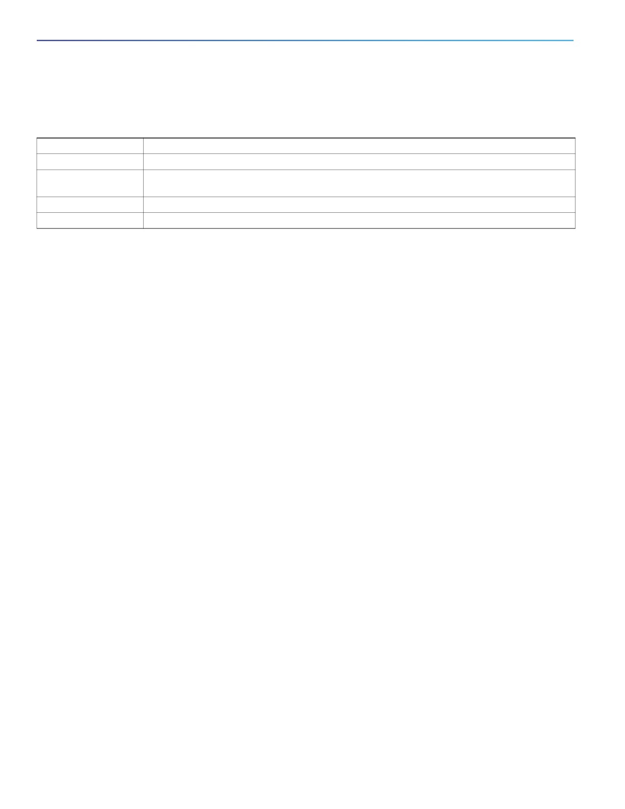
Spanning-Tree Timers
Table 40
Spanning-Tree Timers
Variable
Description
Hello timer
Controls how often the switch broadcasts hello messages to other switches.
Forward-delay timer
Controls how long each of the listening and learning states last before the interface begins
forwarding.
Maximum-age timer
Controls the amount of time the switch stores protocol information received on an interface.
Transmit hold count
Controls the number of BPDUs that can be sent before pausing for 1 second.
Spanning-Tree Configuration Guidelines
If more VLANs are defined in the VTP than there are spanning-tree instances, you can enable PVST+ or rapid PVST+ on
only 128 VLANs on the switch. The remaining VLANs operate with spanning tree disabled. However, you can map
multiple VLANs to the same spanning-tree instances by using MSTP. For more information, see Configuring MSTP,
page 351
If 128 instances of spanning tree are already in use, you can disable spanning tree on one of the VLANs and then enable
it on the VLAN where you want it to run. Use the no spanning-tree vlan vlan-id global configuration command to disable
spanning tree on a specific VLAN, and use the spanning-tree vlan vlan-id global configuration command to enable
spanning tree on the desired VLAN.
Caution: Switches that are not running spanning tree still forward BPDUs that they receive so that the other
switches on the VLAN that have a running spanning-tree instance can break loops. Therefore, spanning tree must
be running on enough switches to break all the loops in the network; for example, at least one switch on each loop
in the VLAN must be running spanning tree. It is not absolutely necessary to run spanning tree on all switches in the
VLAN. However, if you are running spanning tree only on a minimal set of switches, an incautious change to the
network that introduces another loop into the VLAN can result in a broadcast storm.
Note: If you have already used all available spanning-tree instances on your switch, adding another VLAN anywhere in
the VTP domain creates a VLAN that is not running spanning tree on that switch. If you have the default allowed list on
the trunk ports of that switch, the new VLAN is carried on all trunk ports. Depending on the topology of the network, this
could create a loop in the new VLAN that will not be broken, particularly if there are several adjacent switches that have
all run out of spanning-tree instances. You can prevent this possibility by setting up allowed lists on the trunk ports of
switches that have used up their allocation of spanning-tree instances. Setting up allowed lists is not necessary in many
cases and can make it more labor-intensive to add another VLAN to the network.
Spanning-tree commands control the configuration of VLAN spanning-tree instances. You create a spanning-tree
instance when you assign an interface to a VLAN. The spanning-tree instance is removed when the last interface is
moved to another VLAN. You can configure switch and port parameters before a spanning-tree instance is created; these
parameters are applied when the spanning-tree instance is created.
The switch supports PVST+, rapid PVST+, and MSTP, but only one version can be active at any time. (For example, all
VLANs run PVST+, all VLANs run rapid PVST+, or all VLANs run MSTP.) For information about the different spanning-tree
modes and how they interoperate, see Spanning-Tree Interoperability and Backward Compatibility, page 340.
For configuration information about UplinkFast and BackboneFast, see Information About Configuring the Optional
Spanning-Tree Features, page 371.
Caution: Loop guard works only on point-to-point links. We recommend that each end of the link has a directly
connected device that is running STP.
344

Configuring STP
How to Configure STP
How to Configure STP
Changing the Spanning-Tree Mode
Command
Purpose
1.
configure terminal
Enters global configuration mode.
2.
spanning-tree mode {pvst | mst |
Configures a spanning-tree mode.
rapid-pvst}
pvst—Enables PVST+ (the default setting).
mst—Enables MSTP (and RSTP). For more configuration steps, see
Configuring MSTP, page 351
rapid-pvst—Enables rapid PVST+.
3.
interface interface-id
(Recommended for rapid-PVST+ mode only) Specifies an interface to
configure, and enters interface configuration mode. Valid interfaces
include physical ports, VLANs, and port channels.
4.
spanning-tree link-type point-to-point
(Recommended for rapid-PVST+ mode only) Specifies that the link type
for this port is point-to-point.
If you connect this port (local port) to a remote port through a
point-to-point link and the local port becomes a designated port, the
switch negotiates with the remote port and rapidly changes the local
port to the forwarding state.
5.
end
Returns to privileged EXEC mode.
6.
clear spanning-tree detected-protocols
(Recommended for rapid-PVST+ mode only) Restarts the protocol
migration process on the entire switch if any port on the switch is
connected to a port on a legacy IEEE 802.1D switch,
This step is optional if the designated switch detects that this switch is
running rapid PVST+.
345

Configuring STP
How to Configure STP
Configuring the Root Switch
Command
Purpose
1.
configure terminal
Enters global configuration mode.
2.
spanning-tree vlan vlan-id root primary
Configures a switch to become the root for the specified
[diameter net-diameter [hello-time seconds]]
VLAN.
vlan-id—Specifies a single VLAN identified by VLAN ID
number, a range of VLANs separated by a hyphen, or a
series of VLANs separated by a comma.
(Optional) diameter net-diameter—Specifies the
maximum number of switches between any two end
stations.
(Optional) hello-time seconds—Specifies the interval in
seconds between the generation of configuration
messages by the root switch.
3.
end
Returns to privileged EXEC mode.
Configuring a Secondary Root Switch
Command
Purpose
1.
configure terminal
Enters global configuration mode.
2.
spanning-tree vlan vlan-id root secondary
Configures a switch to become the secondary root for the specified
[diameter net-diameter [hello-time
VLAN.
seconds]]
vlan-id—Specifies a single VLAN identified by VLAN ID number,
a range of VLANs separated by a hyphen, or a series of VLANs
separated by a comma. The range is 1 to 4096.
(Optional) diameter net-diameter—Specifies the maximum
number of switches between any two end stations. The range is
2 to 7.
(Optional) hello-time seconds—Specifies the interval in seconds
between the generation of configuration messages by the root
switch. The range is 1 to 10; the default is 2.
Use the same network diameter and hello-time values that you used
when configuring the primary root switch. See Configuring the Root
Switch, page 346.
3.
end
Returns to privileged EXEC mode.
346

Configuring STP
How to Configure STP
Configuring Port Priority
Command
Purpose
1.
configure terminal
Enters global configuration mode.
2.
interface interface-id
Specifies an interface to configure, and enters interface
configuration mode.
Valid interfaces include physical ports and port-channel
logical interfaces (port-channel port-channel-number).
3.
spanning-tree port-priority priority
Configures the port priority for an interface.
4.
spanning-tree vlan vlan-id port-priority priority
Configures the port priority for a VLAN.
5.
end
Returns to privileged EXEC mode.
Configuring Path Cost
Command
Purpose
1.
configure terminal
Enters global configuration mode.
2.
interface interface-id
Specifies an interface to configure, and enters interface
configuration mode. Valid interfaces include physical ports and
port-channel logical interfaces (port-channel
port-channel-number).
3.
spanning-tree cost cost
Configures the cost for an interface.
4.
spanning-tree vlan vlan-id cost cost
Configures the cost for a VLAN.
If a loop occurs, spanning tree uses the path cost when selecting
an interface to place into the forwarding state. A lower path cost
represents higher-speed transmission.
5.
end
Returns to privileged EXEC mode.
Configuring Optional STP Parameters
Before You Begin
Exercise care when configuring the priority, and hello time for STP.
For most situations, we recommend that you use the spanning-tree vlan vlan-id root primary and the spanning-tree
vlan vlan-id root secondary global configuration commands to modify the switch priority.
Command
Purpose
1.
configure terminal
Enters global configuration mode.
2.
spanning-tree vlan vlan-id priority priority
Configures the switch priority of a VLAN.
3.
spanning-tree vlan vlan-id hello-time seconds
Configures the hello time of a VLAN.
4.
spanning-tree vlan vlan-id max-age seconds
Configures the maximum-aging time of a VLAN.
5.
spanning-tree vlan vlan-id forward-time seconds
Configures the forward time of a VLAN.
347

Configuring STP
Monitoring and Maintaining STP
Command
Purpose
6.
spanning-tree vlan vlan-id max-age seconds
Configures the maximum-aging time of a VLAN.
7.
spanning-tree transmit hold-count value
Configures the number of BPDUs that can be sent before
pausing for 1 second.
Note: Changing this parameter to a higher value can have a
significant impact on CPU utilization, especially in
Rapid-PVST mode. Lowering this value can slow down
convergence in certain scenarios. We recommend that you
maintain the default setting.
8.
end
Returns to privileged EXEC mode.
Monitoring and Maintaining STP
Command
Purpose
show spanning-tree active
Displays spanning-tree information on active interfaces only.
show spanning-tree detail
Displays a detailed summary of interface information.
show spanning-tree interface interface-id
Displays spanning-tree information for the specified
interface.
show spanning-tree summary
Displays a summary of interface states.
show spanning-tree vlan vlan-id
Displays spanning-tree VLAN entries.
copy running-config startup-config
(Optional) Saves your entries in the configuration file.
Additional References
The following sections provide references related to switch administration:
348
Configuring STP
Additional References
Related Documents
Related Topic
Document Title
Cisco IOS basic commands
Cisco IOS Configuration Fundamentals Command Reference
VLAN configuration
Configuring VLANs, page 289
Multiple Spanning Tree Protocol configuration
Configuring MSTP, page 351
Optional Spanning-Tree configuration
Configuring Optional Spanning-Tree Features, page 371
Standards
Standards
Title
No new or modified standards are supported by this
—
feature, and support for existing standards has not
been modified by this feature.
MIBs
MIBs
MIBs Link
—
To locate and download MIBs using Cisco IOS XR software, use the
Cisco MIB Locator found at the following URL and choose a platform
under the Cisco Access Products menu:
RFCs
RFCs
Title
No new or modified RFCs are supported by this
—
feature, and support for existing RFCs has not been
modified by this feature.
349
Configuring STP
Additional References
350
Configuring MSTP
Information About Configuring MSTP
This chapter describes how to configure the Cisco implementation of the IEEE 802.1s Multiple STP (MSTP) on the switch.
Note: The multiple spanning-tree (MST) implementation is based on the IEEE 802.1s standard.
The MSTP enables multiple VLANs to be mapped to the same spanning-tree instance, reducing the number of
spanning-tree instances needed to support a large number of VLANs. The MSTP provides for multiple forwarding paths
for data traffic and enables load balancing. It improves the fault tolerance of the network because a failure in one instance
(forwarding path) does not affect other instances (forwarding paths). The most common initial deployment of MSTP is in
the backbone and distribution layers of a Layer 2 switched network. This deployment provides the highly available
network required in a service-provider environment.
When the switch is in the MST mode, the Rapid Spanning Tree Protocol (RSTP), which is based on IEEE 802.1w, is
automatically enabled. The RSTP provides rapid convergence of the spanning tree through explicit handshaking that
eliminates the IEEE 802.1D forwarding delay and quickly transitions root ports and designated ports to the forwarding
state.
Both MSTP and RSTP improve the spanning-tree operation and maintain backward compatibility with equipment that is
based on the (original) IEEE 802.1D spanning tree, with existing Cisco-proprietary Multiple Instance STP (MISTP), and
with existing Cisco per-VLAN spanning-tree plus (PVST+) and rapid per-VLAN spanning-tree plus (rapid PVST+).
MSTP
MSTP, which uses RSTP for rapid convergence, enables VLANs to be grouped into a spanning-tree instance, with each
instance having a spanning-tree topology independent of other spanning-tree instances. This architecture provides
multiple forwarding paths for data traffic, enables load balancing, and reduces the number of spanning-tree instances
required to support a large number of VLANs.
Multiple Spanning-Tree Regions
For switches to participate in multiple spanning-tree (MST) instances, you must consistently configure the switches with
the same MST configuration information. A collection of interconnected switches that have the same MST configuration
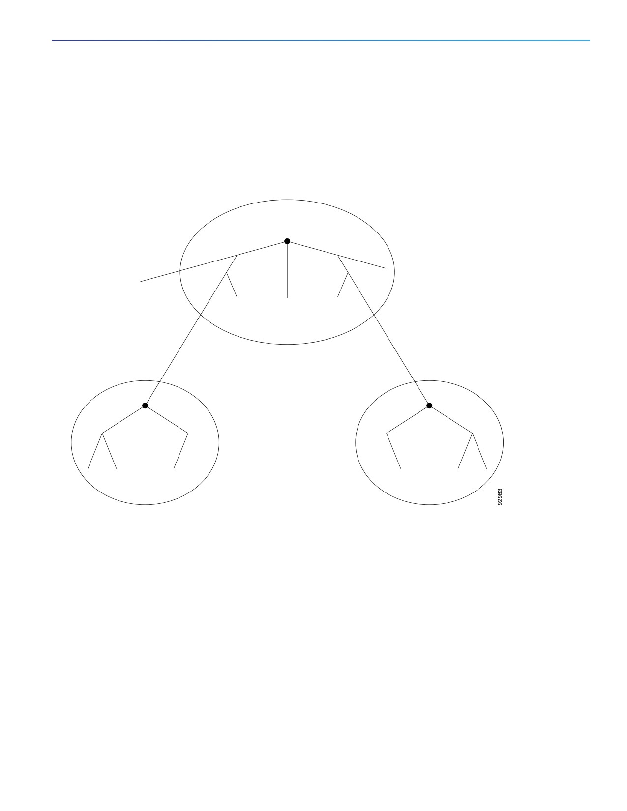
comprises an MST region as shown in Figure 1 on page 3.
The MST configuration controls to which MST region each switch belongs. The configuration includes the name of the
region, the revision number, and the MST VLAN-to-instance assignment map. You configure the switch for a region by
using the spanning-tree mst configuration global configuration command, after which the switch enters the MST
configuration mode. From this mode, you can map VLANs to an MST instance by using the instance MST configuration
command, specify the region name by using the name MST configuration command, and set the revision number by
using the revision MST configuration command.
A region can have one or multiple members with the same MST configuration. Each member must be capable of
processing RSTP bridge protocol data units (BPDUs). There is no limit to the number of MST regions in a network, but
each region can support up to 65 spanning-tree instances. Instances can be identified by any number in the range from
0 to 4096. You can assign a VLAN to only one spanning-tree instance at a time.
351
Configuring MSTP
Information About Configuring MSTP
IST, CIST, and CST
Unlike PVST+ and rapid PVST+ in which all the spanning-tree instances are independent, the MSTP establishes and
maintains two types of spanning trees:
An internal spanning tree (IST), which is the spanning tree that runs in an MST region.
Within each MST region, the MSTP maintains multiple spanning-tree instances. Instance 0 is a special instance for
a region, known as the internal spanning tree (IST). All other MST instances are numbered from 1 to 4096.
The IST is the only spanning-tree instance that sends and receives BPDUs. All of the other spanning-tree instance
information is contained in M-records, which are encapsulated within MSTP BPDUs. Because the MSTP BPDU
carries information for all instances, the number of BPDUs that need to be processed to support multiple
spanning-tree instances is significantly reduced.
All MST instances within the same region share the same protocol timers, but each MST instance has its own
topology parameters, such as root switch ID, root path cost, and so forth. By default, all VLANs are assigned to the
IST.
An MST instance is local to the region; for example, MST instance 1 in region A is independent of MST instance 1
in region B, even if regions A and B are interconnected.
A common and internal spanning tree (CIST), which is a collection of the ISTs in each MST region, and the common
spanning tree (CST) that interconnects the MST regions and single spanning trees.
The spanning tree computed in a region appears as a subtree in the CST that encompasses the entire switched
domain. The CIST is formed by the spanning-tree algorithm running among switches that support the IEEE 802.1w,
IEEE 802.1s, and IEEE 802.1D standards. The CIST inside an MST region is the same as the CST outside a region.
For more information, see Operations Within an MST Region, page 2 and the Operations Between MST Regions, page 3.
Note: The implementation of the IEEE 802.1s standard, changes some of the terminology associated with MST
implementations.
Operations Within an MST Region
The IST connects all the MSTP switches in a region. When the IST converges, the root of the IST becomes the CIST
regional root (called the IST master before the implementation of the IEEE 802.1s standard) as shown in Figure 1 on
page 3. It is the switch within the region with the lowest switch ID and path cost to the CIST root. The CIST regional root
is also the CIST root if there is only one region in the network. If the CIST root is outside the region, one of the MSTP
switches at the boundary of the region is selected as the CIST regional root.
When an MSTP switch initializes, it sends BPDUs claiming itself as the root of the CIST and the CIST regional root, with
both of the path costs to the CIST root and to the CIST regional root set to zero. The switch also initializes all of its MST
instances and claims to be the root for all of them. If the switch receives superior MST root information (lower switch ID,
lower path cost, and so forth) than currently stored for the port, it relinquishes its claim as the CIST regional root.
During initialization, a region might have many subregions, each with its own CIST regional root. As switches receive
superior IST information, they leave their old subregions and join the new subregion that contains the true CIST regional
root. All subregions shrink, except for the one that contains the true CIST regional root.
For correct operation, all switches in the MST region must agree on the same CIST regional root. Therefore, any two
switches in the region only synchronize their port roles for an MST instance if they converge to a common CIST regional
root.
Operations Between MST Regions
If there are multiple regions or legacy IEEE 802.1D switches within the network, MSTP establishes and maintains the CST,
which includes all MST regions and all legacy STP switches in the network. The MST instances combine with the IST at
the boundary of the region to become the CST.
352
Configuring MSTP
Information About Configuring MSTP
The IST connects all the MSTP switches in the region and appears as a subtree in the CIST that encompasses the entire
switched domain. The root of the subtree is the CIST regional root. The MST region appears as a virtual switch to adjacent
STP switches and MST regions.
Figure 1 on page 3 shows a network with three MST regions and a legacy IEEE 802.1D switch (D). The CIST regional root
for region 1 (A) is also the CIST root. The CIST regional root for region 2 (B) and the CIST regional root for region 3 (C)
are the roots for their respective subtrees within the CIST. The RSTP runs in all regions.
Figure 39
MST Regions, CIST Masters, and CST Root
IST master
A
and CST root
D
Legacy IEEE 802.1D
MST Region 1
B
IST master
C
IST master
MST Region 2
MST Region 3
Only the CST instance sends and receives BPDUs, and MST instances add their spanning-tree information into the
BPDUs to interact with neighboring switches and compute the final spanning-tree topology. Because of this, the
spanning-tree parameters related to BPDU transmission (for example, hello time, forward time, max-age, and max-hops)
are configured only on the CST instance but affect all MST instances. Parameters related to the spanning-tree topology
(for example, switch priority, port VLAN cost, and port VLAN priority) can be configured on both the CST instance and
the MST instance.
MSTP switches use Version 3 RSTP BPDUs or IEEE 802.1D STP BPDUs to communicate with legacy IEEE 802.1D
switches. MSTP switches use MSTP BPDUs to communicate with MSTP switches.
IEEE 802.1s Terminology
Some MST naming conventions used in Cisco’s prestandard implementation have been changed to identify some internal
or regional parameters. These parameters are significant only within an MST region, as opposed to external parameters
that are relevant to the whole network. Because the CIST is the only spanning-tree instance that spans the whole
network, only the CIST parameters require the external rather than the internal or regional qualifiers.
The CIST root is the root switch for the unique instance that spans the whole network, the CIST.
353

Configuring MSTP
Information About Configuring MSTP
The CIST external root path cost is the cost to the CIST root. This cost is left unchanged within an MST region.
Remember that an MST region looks like a single switch for the CIST. The CIST external root path cost is the root
path cost calculated between these virtual switches and switches that do not belong to any region.
The CIST regional root was called the IST master in the prestandard implementation. If the CIST root is in the region,
the CIST regional root is the CIST root. Otherwise, the CIST regional root is the closest switch to the CIST root in the
region. The CIST regional root acts as a root switch for the IST.
The CIST internal root path cost is the cost to the CIST regional root in a region. This cost is only relevant to the IST,
instance 0.
Table 41 on page 354 compares the IEEE standard and the Cisco prestandard terminology.
Table 41
IEEE standard and the Cisco Prestandard Terminology
IEEE Standard
Cisco Prestandard
Cisco Standard
CIST regional root
IST master
CIST regional root
CIST internal root path cost
IST master path cost
CIST internal path cost
CIST external root path cost
Root path cost
Root path cost
MSTI regional root
Instance root
Instance root
MSTI internal root path cost
Root path cost
Root path cost
Hop Count
The IST and MST instances do not use the message-age and maximum-age information in the configuration BPDU to
compute the spanning-tree topology. Instead, they use the path cost to the root and a hop-count mechanism similar to
the IP time-to-live (TTL) mechanism.
By using the spanning-tree mst max-hops global configuration command, you can configure the maximum hops inside
the region and apply it to the IST and all MST instances in that region. The hop count achieves the same result as the
message-age information (triggers a reconfiguration). The root switch of the instance always sends a BPDU (or
M-record) with a cost of 0 and the hop count set to the maximum value. When a switch receives this BPDU, it decrements
the received remaining hop count by one and propagates this value as the remaining hop count in the BPDUs it generates.
When the count reaches zero, the switch discards the BPDU and ages the information held for the port.
The message-age and maximum-age information in the RSTP portion of the BPDU remain the same throughout the
region, and the same values are propagated by the region designated ports at the boundary.
Boundary Ports
In the Cisco prestandard implementation, a boundary port connects an MST region to a single spanning-tree region
running RSTP, to a single spanning-tree region running PVST+ or rapid PVST+, or to another MST region with a different
MST configuration. A boundary port also connects to a LAN, the designated switch of which is either a single
spanning-tree switch or a switch with a different MST configuration.
There is no definition of a boundary port in the IEEE 802.1s standard. The IEEE 802.1Q-2002 standard identifies two kinds
of messages that a port can receive: internal (coming from the same region) and external. When a message is external,
it is received only by the CIST. If the CIST role is root or alternate, or if the external BPDU is a topology change, it could
have an impact on the MST instances. When a message is internal, the CIST part is received by the CIST, and each MST
instance receives its respective M-record. The Cisco prestandard implementation treats a port that receives an external
message as a boundary port. This means a port cannot receive a mix of internal and external messages.
An MST region includes both switches and LANs. A segment belongs to the region of its designated port. Therefore, a
port in a different region than the designated port for a segment is a boundary port. This definition allows two ports
internal to a region to share a segment with a port belonging to a different region, creating the possibility of receiving
both internal and external messages on a port.
354
Configuring MSTP
Information About Configuring MSTP
The primary change from the Cisco prestandard implementation is that a designated port is not defined as boundary,
unless it is running in an STP-compatible mode.
Note: If there is a legacy STP switch on the segment, messages are always considered external.
The other change from the prestandard implementation is that the CIST regional root switch ID field is now inserted where
an RSTP or legacy IEEE 802.1Q switch has the sender switch ID. The whole region performs like a single virtual switch
by sending a consistent sender switch ID to neighboring switches. In this example, switch C would receive a BPDU with
the same consistent sender switch ID of root, whether or not A or B is designated for the segment.
IEEE 802.1s Implementation
The Cisco implementation of the IEEE MST standard includes features required to meet the standard, as well as some of
the desirable prestandard functionality that is not yet incorporated into the published standard.
Port Role Naming Change
The boundary role is no longer in the final MST standard, but this boundary concept is maintained in Cisco’s
implementation. However, an MST instance port at a boundary of the region might not follow the state of the
corresponding CIST port. Two cases exist now:
The boundary port is the root port of the CIST regional root—When the CIST instance port is proposed and is in sync,
it can send back an agreement and move to the forwarding state only after all the corresponding MSTI ports are in
sync (and forwarding). The MSTI ports now have a special master role.
The boundary port is not the root port of the CIST regional root—The MSTI ports follow the state and role of the CIST
port. The standard provides less information, and it might be difficult to understand why an MSTI port can be
alternately blocking when it receives no BPDUs (MRecords). In this case, although the boundary role no longer exists,
the show commands identify a port as boundary in the type column of the output.
Interoperation Between Legacy and Standard Switches
Because automatic detection of prestandard switches can fail, you can use an interface configuration command to
identify prestandard ports. A region cannot be formed between a standard and a prestandard switch, but they can
interoperate by using the CIST. Only the capability of load balancing over different instances is lost in that particular case.
The CLI displays different flags depending on the port configuration when a port receives prestandard BPDUs. A syslog
message also appears the first time a switch receives a prestandard BPDU on a port that has not been configured for
prestandard BPDU transmission.
Figure 2 on page 6 illustrates this scenario. Assume that A is a standard switch and B a prestandard switch, both
configured to be in the same region. A is the root switch for the CIST, and B has a root port (BX) on segment X and an
alternate port (BY) on segment Y. If segment Y flaps, and the port on BY becomes the alternate before sending out a
single prestandard BPDU, AY cannot detect that a prestandard switch is connected to Y and continues to send standard
BPDUs. The port BY is fixed in a boundary, and no load balancing is possible between A and B. The same problem exists
on segment X, but B might transmit topology changes.
355
Configuring MSTP
Information About Configuring MSTP
Figure 40
Standard and Prestandard Switch Interoperation
Segment X
MST
Region
Switch A
Switch B
Segment Y
Note: We recommend that you minimize the interaction between standard and prestandard MST implementations.
Detecting Unidirectional Link Failure
This feature is not yet present in the IEEE MST standard, but it is included in this Cisco IOS release. The software checks
the consistency of the port role and state in the received BPDUs to detect unidirectional link failures that could cause
bridging loops.
When a designated port detects a conflict, it keeps its role, but reverts to discarding state because disrupting connectivity
in case of inconsistency is preferable to opening a bridging loop.
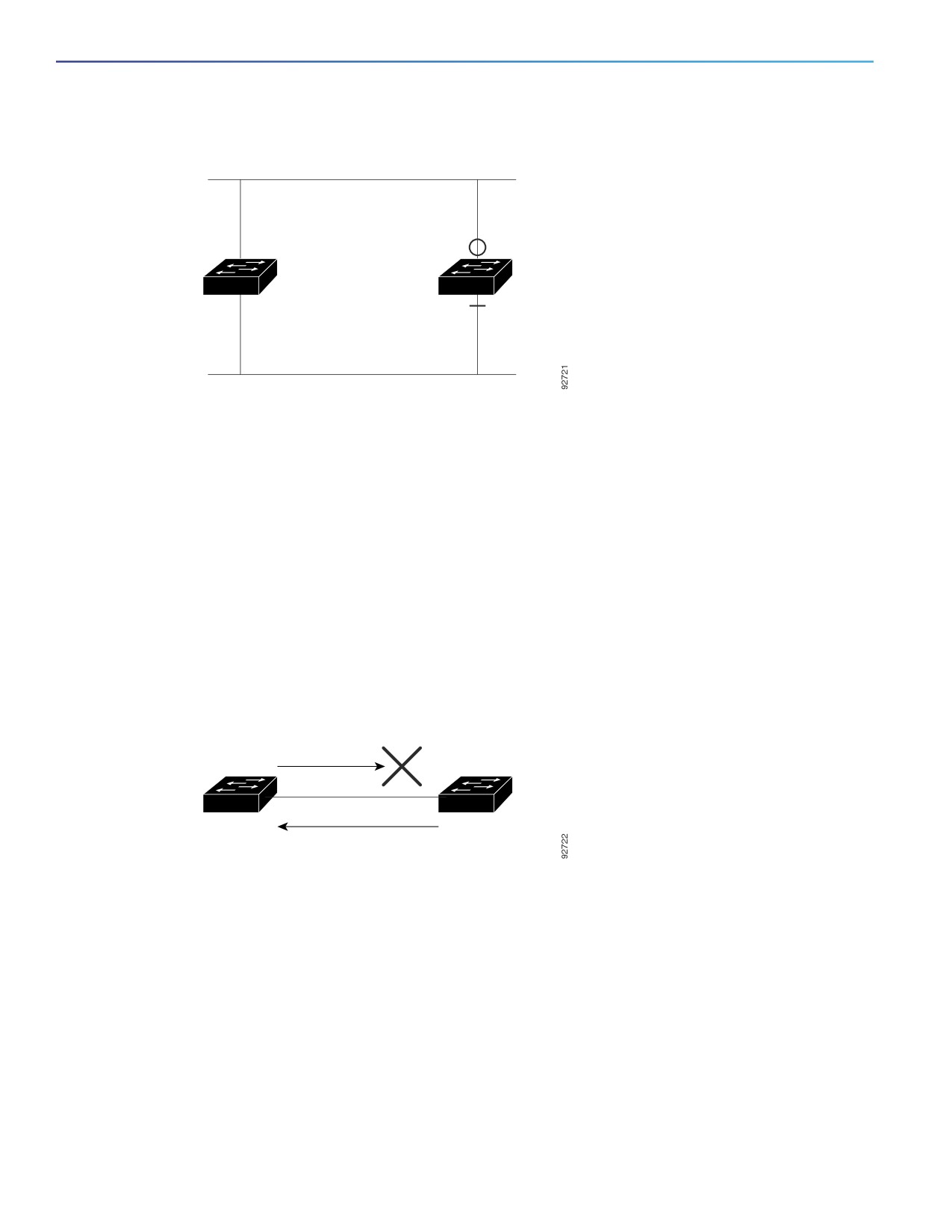
Figure 3 on page 6 illustrates a unidirectional link failure that typically creates a bridging loop. Switch A is the root switch,
and its BPDUs are lost on the link leading to switch B. RSTP and MST BPDUs include the role and state of the sending
port. With this information, switch A can detect that switch B does not react to the superior BPDUs it sends and that
switch B is the designated, not root switch. As a result, switch A blocks (or keeps blocking) its port, preventing the
bridging loop.
Figure 41
Detecting Unidirectional Link Failure
Superior
Switch
Switch
BPDU
A
B
Inferior BPDU,
Designated + Learning bit set
Interoperability with IEEE 802.1D STP
A switch running MSTP supports a built-in protocol migration mechanism that enables it to interoperate with legacy IEEE
802.1D switches. If this switch receives a legacy IEEE 802.1D configuration BPDU (a BPDU with the protocol version set
to 0), it sends only IEEE 802.1D BPDUs on that port. An MSTP switch also can detect that a port is at the boundary of a
region when it receives a legacy BPDU, an MSTP BPDU (Version 3) associated with a different region, or an RSTP BPDU
(Version 2).
However, the switch does not automatically revert to the MSTP mode if it no longer receives IEEE 802.1D BPDUs because
it cannot detect whether the legacy switch has been removed from the link unless the legacy switch is the designated
switch. A switch might also continue to assign a boundary role to a port when the switch to which this switch is connected
has joined the region. To restart the protocol migration process (force the renegotiation with neighboring switches), use
the clear spanning-tree detected-protocols privileged EXEC command.
356

Configuring MSTP
Information About Configuring MSTP
If all the legacy switches on the link are RSTP switches, they can process MSTP BPDUs as if they are RSTP BPDUs.
Therefore, MSTP switches send either a Version 0 configuration and TCN BPDUs or Version 3 MSTP BPDUs on a
boundary port. A boundary port connects to a LAN, the designated switch of which is either a single spanning-tree switch
or a switch with a different MST configuration.
RSTP
The RSTP takes advantage of point-to-point wiring and provides rapid convergence of the spanning tree.
Reconfiguration of the spanning tree can occur in less than 1 second (in contrast to 50 seconds with the default settings
in the IEEE 802.1D spanning tree).
Port Roles and the Active Topology
The RSTP provides rapid convergence of the spanning tree by assigning port roles and by learning the active topology.
The RSTP builds upon the IEEE 802.1D STP to select the switch with the highest switch priority (lowest numerical priority
value) as the root switch as described in the Configuring STP, page 1. Then the RSTP assigns one of these port roles to
individual ports:
Root port—Provides the best path (lowest cost) when the switch forwards packets to the root switch.
Designated port—Connects to the designated switch, which incurs the lowest path cost when forwarding packets
from that LAN to the root switch. The port through which the designated switch is attached to the LAN is called the
designated port.
Alternate port—Offers an alternate path toward the root switch to that provided by the current root port.
Backup port—Acts as a backup for the path provided by a designated port toward the leaves of the spanning tree. A
backup port can exist only when two ports are connected in a loopback by a point-to-point link or when a switch
has two or more connections to a shared LAN segment.
Disabled port—Has no role within the operation of the spanning tree.
A port with the root or a designated port role is included in the active topology. A port with the alternate or backup port
role is excluded from the active topology.
In a stable topology with consistent port roles throughout the network, the RSTP ensures that every root port and
designated port immediately transition to the forwarding state while all alternate and backup ports are always in the
discarding state (equivalent to blocking in IEEE 802.1D). The port state controls the operation of the forwarding and
learning processes. Table 42 on page 357 provides a comparison of IEEE 802.1D and RSTP port states.
Table 42
EEE 802.1D and RSTP Port States
Operational Status
STP Port State
RSTP Port State
Is Port Included in the
(IEEE 802.1D)
Active Topology?
Enabled
Blocking
Discarding
No
Enabled
Listening
Discarding
No
Enabled
Learning
Learning
Yes
Enabled
Forwarding
Forwarding
Yes
Disabled
Disabled
Discarding
No
To be consistent with Cisco STP implementations, this guide defines the port state as blocking instead of discarding.
Designated ports start in the listening state.
357
Configuring MSTP
Information About Configuring MSTP
Rapid Convergence
The RSTP provides for rapid recovery of connectivity following the failure of a switch, a switch port, or a LAN. It provides
rapid convergence for edge ports, new root ports, and ports connected through point-to-point links as follows:
Edge ports—If you configure a port as an edge port on an RSTP switch by using the spanning-tree portfast interface
configuration command, the edge port immediately transitions to the forwarding state. An edge port is the same as
a Port Fast-enabled port, and you should enable it only on ports that connect to a single end station.
Root ports—If the RSTP selects a new root port, it blocks the old root port and immediately transitions the new root
port to the forwarding state.
Point-to-point links—If you connect a port to another port through a point-to-point link and the local port becomes
a designated port, it negotiates a rapid transition with the other port by using the proposal-agreement handshake to
ensure a loop-free topology.
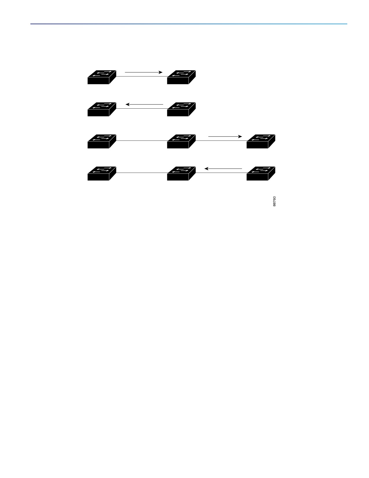
As shown in Figure 4 on page 9, Switch A is connected to Switch B through a point-to-point link, and all of the ports
are in the blocking state. Assume that the priority of Switch A is a smaller numerical value than the priority of Switch
B. Switch A sends a proposal message (a configuration BPDU with the proposal flag set) to Switch B, proposing itself
as the designated switch.
After receiving the proposal message, Switch B selects as its new root port the port from which the proposal
message was received, forces all nonedge ports to the blocking state, and sends an agreement message (a BPDU
with the agreement flag set) through its new root port.
After receiving Switch B’s agreement message, Switch A also immediately transitions its designated port to the
forwarding state. No loops in the network are formed because Switch B blocked all of its nonedge ports and because
there is a point-to-point link between Switches A and B.
When Switch C is connected to Switch B, a similar set of handshaking messages are exchanged. Switch C selects
the port connected to Switch B as its root port, and both ends immediately transition to the forwarding state. With
each iteration of this handshaking process, one more switch joins the active topology. As the network converges,
this proposal-agreement handshaking progresses from the root toward the leaves of the spanning tree.
The switch learns the link type from the port duplex mode: a full-duplex port is considered to have a point-to-point
connection; a half-duplex port is considered to have a shared connection. You can override the default setting that
is controlled by the duplex setting by using the spanning-tree link-type interface configuration command.
358
Configuring MSTP
Information About Configuring MSTP
Figure 42
Proposal and Agreement Handshaking for Rapid Convergence
Switch A
Switch B
Proposal
Designated
Root
Agreement
switch
F
F
DP
RP
Designated
Root
switch
Switch C
Proposal
F
F
DP
RP
Designated
Root
switch
Agreement
F
F
F
F
DP
RP
DP
RP
DP = designated port
RP = root port
F = forwarding
Synchronization of Port Roles
When the switch receives a proposal message on one of its ports and that port is selected as the new root port, the RSTP
forces all other ports to synchronize with the new root information.
The switch is synchronized with superior root information received on the root port if all other ports are synchronized. An
individual port on the switch is synchronized if
That port is in the blocking state.
It is an edge port (a port configured to be at the edge of the network).
If a designated port is in the forwarding state and is not configured as an edge port, it transitions to the blocking state
when the RSTP forces it to synchronize with new root information. In general, when the RSTP forces a port to synchronize
with root information and the port does not satisfy any of the above conditions, its port state is set to blocking.
After ensuring that all of the ports are synchronized, the switch sends an agreement message to the designated switch
corresponding to its root port. When the switches connected by a point-to-point link are in agreement about their port
roles, the RSTP immediately transitions the port states to forwarding. The sequence of events is shown in Figure 5 on
page 10.
359
Configuring MSTP
Information About Configuring MSTP
Figure 43
Sequence of Events During Rapid Convergence
4.
Agreement
1. Proposal
5. Forward
Edge port
2. Block
3. Block
9. Forward
11. Forward
8. Agreement
6. Proposal
7. Proposal
10. Agreement
Root port
Designated port
Bridge Protocol Data Unit Format and Processing
The RSTP BPDU format is the same as the IEEE 802.1D BPDU format except that the protocol version is set to 2. A new
1-byte Version 1 Length field is set to zero, which means that no version 1 protocol information is present. Table 3 shows
the RSTP flag fields.
Table 43
RSTP Flag Fields
Bit
Function
0
Topology change (TC)
1
Proposal
2-3:
Port role:
00
Unknown
01
Alternate port
10
Root port
11
Designated port
4
Learning
5
Forwarding
6
Agreement
7
Topology change acknowledgement (TCA)
The sending switch sets the proposal flag in the RSTP BPDU to propose itself as the designated switch on that LAN. The
port role in the proposal message is always set to the designated port.
The sending switch sets the agreement flag in the RSTP BPDU to accept the previous proposal. The port role in the
agreement message is always set to the root port.
360
Configuring MSTP
Information About Configuring MSTP
The RSTP does not have a separate topology change notification (TCN) BPDU. It uses the topology change (TC) flag to
show the topology changes. However, for interoperability with IEEE 802.1D switches, the RSTP switch processes and
generates TCN BPDUs.
The learning and forwarding flags are set according to the state of the sending port.
Processing Superior BPDU Information
If a port receives superior root information (lower switch ID, lower path cost, and so forth) than currently stored for the
port, the RSTP triggers a reconfiguration. If the port is proposed and is selected as the new root port, RSTP forces all
the other ports to synchronize.
If the BPDU received is an RSTP BPDU with the proposal flag set, the switch sends an agreement message after all of
the other ports are synchronized. If the BPDU is an IEEE 802.1D BPDU, the switch does not set the proposal flag and
starts the forward-delay timer for the port. The new root port requires twice the forward-delay time to transition to the
forwarding state.
If the superior information received on the port causes the port to become a backup or alternate port, RSTP sets the port
to the blocking state but does not send the agreement message. The designated port continues sending BPDUs with the
proposal flag set until the forward-delay timer expires, at which time the port transitions to the forwarding state.
Processing Inferior BPDU Information
If a designated port receives an inferior BPDU (higher switch ID, higher path cost, and so forth than currently stored for
the port) with a designated port role, it immediately replies with its own information.
Topology Changes
This section describes the differences between the RSTP and the IEEE 802.1D in handling spanning-tree topology
changes.
Detection—Unlike IEEE 802.1D in which any transition between the blocking and the forwarding state causes a
topology change, only transitions from the blocking to the forwarding state cause a topology change with RSTP (only
an increase in connectivity is considered a topology change). State changes on an edge port do not cause a topology
change. When an RSTP switch detects a topology change, it deletes the learned information on all of its nonedge
ports except on those from which it received the TC notification.
Notification—Unlike IEEE 802.1D, which uses TCN BPDUs, the RSTP does not use them. However, for IEEE 802.1D
interoperability, an RSTP switch processes and generates TCN BPDUs.
Acknowledgement—When an RSTP switch receives a TCN message on a designated port from an IEEE 802.1D
switch, it replies with an IEEE 802.1D configuration BPDU with the TCA bit set. However, if the TC-while timer (the
same as the topology-change timer in IEEE 802.1D) is active on a root port connected to an IEEE 802.1D switch and
a configuration BPDU with the TCA bit set is received, the TC-while timer is reset.
This behavior is only required to support IEEE 802.1D switches. The RSTP BPDUs never have the TCA bit set.
Propagation—When an RSTP switch receives a TC message from another switch through a designated or root port,
it propagates the change to all of its nonedge, designated ports and to the root port (excluding the port on which it
is received). The switch starts the TC-while timer for all such ports and flushes the information learned on them.
Protocol migration—For backward compatibility with IEEE 802.1D switches, RSTP selectively sends IEEE 802.1D
configuration BPDUs and TCN BPDUs on a per-port basis.
When a port is initialized, the migrate-delay timer is started (specifies the minimum time during which RSTP BPDUs
are sent), and RSTP BPDUs are sent. While this timer is active, the switch processes all BPDUs received on that port
and ignores the protocol type.
361

Configuring MSTP
Information About Configuring MSTP
If the switch receives an IEEE 802.1D BPDU after the port migration-delay timer has expired, it assumes that it is
connected to an IEEE 802.1D switch and starts using only IEEE 802.1D BPDUs. However, if the RSTP switch is using
IEEE 802.1D BPDUs on a port and receives an RSTP BPDU after the timer has expired, it restarts the timer and starts
using RSTP BPDUs on that port.
Default MSTP Settings
Table 44
Default MSTP Settings
Feature
Default Setting
Spanning-tree mode
PVST+ (Rapid PVST+ and MSTP are disabled)
Switch priority (configurable on a per-CIST port basis)
32768
Spanning-tree port priority (configurable on a per-CIST port basis)
128
Spanning-tree port cost (configurable on a per-CIST port basis)
1000 Mbps: 4
100 Mbps: 19
10 Mbps: 100
Hello time
2 seconds
Forward-delay time
15 seconds
Maximum-aging time
20 seconds
Maximum hop count
20 hops
MSTP Configuration Guidelines
These are the configuration guidelines for MSTP:
When you enable MST by using the spanning-tree mode mst global configuration command, RSTP is automatically
enabled.
For two or more switches to be in the same MST region, they must have the same VLAN-to-instance map, the same
configuration revision number, and the same name.
The switch supports up to 65 MST instances. The number of VLANs that can be mapped to a particular MST instance
is unlimited.
PVST+, rapid PVST+, and MSTP are supported, but only one version can be active at any time. (For example, all
VLANs run PVST+, all VLANs run rapid PVST+, or all VLANs run MSTP.) For more information, see “Spanning-Tree
Interoperability and Backward Compatibility” section on page 10.
VTP propagation of the MST configuration is not supported. However, you can manually configure the MST
configuration (region name, revision number, and VLAN-to-instance mapping) on each switch within the MST region
by using the command-line interface (CLI) or through the SNMP support.
For load balancing across redundant paths in the network to work, all VLAN-to-instance mapping assignments must
match; otherwise, all traffic flows on a single link.
All MST boundary ports must be forwarding for load balancing between a PVST+ and an MST cloud or between a
rapid-PVST+ and an MST cloud. For this to occur, the IST master of the MST cloud should also be the root of the
CST. If the MST cloud consists of multiple MST regions, one of the MST regions must contain the CST root, and all
of the other MST regions must have a better path to the root contained within the MST cloud than a path through the
PVST+ or rapid-PVST+ cloud. You might have to manually configure the switches in the clouds.
362
Configuring MSTP
Information About Configuring MSTP
Partitioning the network into a large number of regions is not recommended. However, if this situation is unavoidable,
we recommend that you partition the switched LAN into smaller LANs interconnected by routers or non-Layer 2
devices.
For configuration information about UplinkFast and BackboneFast, see “Information About Configuring the Optional
Spanning-Tree Features” section on page 1.
MST Region Configuration and Enabling MSTP
For two or more switches to be in the same MST region, they must have the same VLAN-to-instance mapping, the same
configuration revision number, and the same name.
A region can have one member or multiple members with the same MST configuration; each member must be capable
of processing RSTP BPDUs. There is no limit to the number of MST regions in a network, but each region can only support
up to 65 spanning-tree instances. You can assign a VLAN to only one spanning-tree instance at a time.
Root Switch
The switch maintains a spanning-tree instance for the group of VLANs mapped to it. A switch ID, consisting of the switch
priority and the switch MAC address, is associated with each instance. For a group of VLANs, the switch with the lowest
switch ID becomes the root switch.
To configure a switch to become the root, use the spanning-tree mst instance-id root global configuration command
to modify the switch priority from the default value (32768) to a significantly lower value so that the switch becomes the
root switch for the specified spanning-tree instance. When you enter this command, the switch checks the switch
priorities of the root switches. Because of the extended system ID support, the switch sets its own priority for the
specified instance to 24576 if this value will cause this switch to become the root for the specified spanning-tree
instance.
If any root switch for the specified instance has a switch priority lower than 24576, the switch sets its own priority
to 4096 less than the lowest switch priority. (4096 is the value of the least-significant bit of a 4-bit switch priority value
as shown in Table 1 on page 4.)
If your network consists of switches that both do and do not support the extended system ID, it is unlikely that the switch
with the extended system ID support will become the root switch. The extended system ID increases the switch priority
value every time the VLAN number is greater than the priority of the connected switches running older software.
The root switch for each spanning-tree instance should be a backbone or distribution switch. Do not configure an access
switch as the spanning-tree primary root.
Use the diameter keyword, which is available only for MST instance 0, to specify the Layer 2 network diameter (that is,
the maximum number of switch hops between any two end stations in the Layer 2 network). When you specify the
network diameter, the switch automatically sets an optimal hello time, forward-delay time, and maximum-age time for a
network of that diameter, which can significantly reduce the convergence time. You can use the hello keyword to override
the automatically calculated hello time.
Secondary Root Switch
When you configure a switch with the extended system ID support as the secondary root, the switch priority is modified
from the default value (32768) to 28672. The switch is then likely to become the root switch for the specified instance if
the primary root switch fails. This is assuming that the other network switches use the default switch priority of 32768
and therefore are unlikely to become the root switch.
You can execute this command on more than one switch to configure multiple backup root switches. Use the same
network diameter and hello-time values that you used when you configured the primary root switch with the
spanning-tree mst instance-id root primary global configuration command.
363
Configuring MSTP
How to Configure MSTP
Port Priority
If a loop occurs, the MSTP uses the port priority when selecting an interface to put into the forwarding state. You can
assign higher priority values (lower numerical values) to interfaces that you want selected first and lower priority values
(higher numerical values) that you want selected last. If all interfaces have the same priority value, the MSTP puts the
interface with the lowest interface number in the forwarding state and blocks the other interfaces.
Path Cost
The MSTP path cost default value is derived from the media speed of an interface. If a loop occurs, the MSTP uses cost
when selecting an interface to put in the forwarding state. You can assign lower cost values to interfaces that you want
selected first and higher cost values that you want selected last. If all interfaces have the same cost value, the MSTP puts
the interface with the lowest interface number in the forwarding state and blocks the other interfaces.
Link Type to Ensure Rapid Transitions
If you connect a port to another port through a point-to-point link and the local port becomes a designated port, the
RSTP negotiates a rapid transition with the other port by using the proposal-agreement handshake to ensure a loop-free
topology as described in the Rapid Convergence, page 8.
By default, the link type is controlled from the duplex mode of the interface: a full-duplex port is considered to have a
point-to-point connection; a half-duplex port is considered to have a shared connection. If you have a half-duplex link
physically connected point-to-point to a single port on a remote switch running MSTP, you can override the default
setting of the link type and enable rapid transitions to the forwarding state.
Neighbor Type
A topology could contain both prestandard and IEEE 802.1s standard compliant devices. By default, ports can
automatically detect prestandard devices, but they can still receive both standard and prestandard BPDUs. When there
is a mismatch between a device and its neighbor, only the CIST runs on the interface.
You can choose to set a port to send only prestandard BPDUs. The prestandard flag appears in all the show commands,
even if the port is in STP compatibility mode.
Restarting the Protocol Migration Process
A switch running MSTP supports a built-in protocol migration mechanism that enables it to interoperate with legacy IEEE
802.1D switches. If this switch receives a legacy IEEE 802.1D configuration BPDU (a BPDU with the protocol version set
to 0), it sends only IEEE 802.1D BPDUs on that port. An MSTP switch also can detect that a port is at the boundary of a
region when it receives a legacy BPDU, an MST BPDU (Version 3) associated with a different region, or an RST BPDU
(Version 2).
However, the switch does not automatically revert to the MSTP mode if it no longer receives IEEE 802.1D BPDUs because
it cannot detect whether the legacy switch has been removed from the link unless the legacy switch is the designated
switch. A switch also might continue to assign a boundary role to a port when the switch to which it is connected has
joined the region.
How to Configure MSTP
Specifying the MST Region Configuration and Enabling MSTP
This task is required.
364

Configuring MSTP
How to Configure MSTP
Command
Purpose
1.
configure terminal
Enters global configuration mode.
2.
spanning-tree mst configuration
Enters MST configuration mode.
3.
instance instance-id vlan vlan-range
Maps VLANs to an MST instance.
instance-id—range is 0 to 4096.
vlan vlan-range—range is 1 to 4096.
When you map VLANs to an MST instance, the mapping is
incremental, and the VLANs specified in the command are added to
or removed from the VLANs that were previously mapped.
To specify a VLAN range, use a hyphen; for example, instance 1 vlan
1-63 maps VLANs 1 through 63 to MST instance 1.
To specify a VLAN series, use a comma; for example, instance 1 vlan 10,
20, 30 maps VLANs 10, 20, and 30 to MST instance 1.
4.
name name
Specifies the configuration name. The name string has a maximum length
of 32 characters and is case sensitive.
5.
revision version
Specifies the configuration revision number. The range is 0 to 65535.
6.
show pending
Verifies your configuration by displaying the pending configuration.
7.
exit
Applies all changes, and returns to global configuration mode.
8.
spanning-tree mode mst
Enables MSTP. RSTP is also enabled.
Caution: Changing spanning-tree modes can disrupt traffic because
all spanning-tree instances are stopped for the previous mode and
restarted in the new mode.
You cannot run both MSTP and PVST+ or both MSTP and rapid PVST+ at
the same time.
9.
end
Returns to privileged EXEC mode.
Configuring the Root Switch
Before You Begin
After configuring the switch as the root switch, we recommend that you avoid manually configuring the hello time,
forward-delay time, and maximum-age time through the spanning-tree mst hello-time, spanning-tree mst
forward-time, and the spanning-tree mst max-age global configuration commands.
This task is optional.
365