Cisco Industrial Ethernet 4000, 4010 and 5000 Switch Software. Configuration Guide (2022) - page 13

Configuring VLANs
How to Configure VLANs
Load Sharing Using STP Port Priorities
Command
Purpose
1.
configure terminal
Enters global configuration mode on Switch A.
2.
vtp domain domain-name
Configures a VTP administrative domain.
The domain name can be 1 to 32 characters.
3.
vtp mode server
Configures Switch A as the VTP server.
4.
end
Returns to privileged EXEC mode.
5.
show vtp status
Verifies the VTP configuration on both Switch A and Switch B.
6.
show vlan
Verifies that the VLANs exist in the database on Switch A.
7.
configure terminal
Enters global configuration mode.
8.
interface interface-id_1
Defines the interface to be configured as a trunk, and enters interface
configuration mode.
9.
switchport mode trunk
Configures the port as a trunk port.
10.
end
Returns to privileged EXEC mode.
11.
show interfaces interface-id_1 switchport
Verifes the VLAN configuration.
12.
Repeat Steps 7 through 10 on Switch A for
a second port in the switch.
13.
Repeat Steps 7 through 10 on Switch B to
configure the trunk ports that connect to the
trunk ports configured on Switch A.
14.
show vlan
When the trunk links come up, VTP passes the VTP and VLAN
information to Switch B. Verifies that Switch B has learned the VLAN
configuration.
15.
configure terminal
Enters global configuration mode on Switch A.
16.
interface interface-id_1
Defines the interface to set the STP port priority, and enters interface
configuration mode.
17.
spanning-tree vlan 8-10 port-priority 16
Assigns the port priority of 16 for VLANs 8 through 10.
18.
exit
Returns to global configuration mode.
19.
interface interface-id_2
Defines the interface to set the STP port priority, and enters interface
configuration mode.
20.
spanning-tree vlan 3-6 port-priority 16
Assigns the port priority of 16 for VLANs 3 through 6.
21.
end
Returns to privileged EXEC mode.
Configuring Load Sharing Using STP Path Cost
Command
Purpose
1.
configure terminal
Enters global configuration mode on Switch A.
2.
interface interface-id_1
Defines the interface to be configured as a trunk, and enters interface
configuration mode.
3.
switchport mode trunk
Configures the port as a trunk port.
4.
exit
Returns to global configuration mode.
5.
Repeat Steps 2 through 4 on a second interface in Switch A.
6.
end
Returns to privileged EXEC mode.
306

Configuring VLANs
How to Configure VLANs
Command
Purpose
7.
show running-config
Verifies your entries. In the display, make sure that the interfaces are
configured as trunk ports.
8.
show vlan
When the trunk links come up, Switch A receives the VTP information
from the other switches. Verifies that Switch A has learned the VLAN
configuration.
9.
configure terminal
Enters global configuration mode.
10.
interface interface-id_1
Defines the interface on which to set the STP cost, and enters interface
configuration mode.
11.
spanning-tree vlan 2-4 cost 30
Sets the spanning-tree path cost to 30 for VLANs 2 through 4.
12.
end
Returns to global configuration mode.
13.
Repeat Steps 9 through 12 on the other
configured trunk interface on Switch A,
and set the spanning-tree path cost to 30
for VLANs 8, 9, and 10.
14.
exit
Returns to privileged EXEC mode.
15.
show running-config
Verifies your entries. In the display, verify that the path costs are set
correctly for both trunk interfaces.
Configuring the VMPS Client
You configure dynamic VLANs by using the VMPS (VLAN Membership Policy Server). The switch can be a VMPS client;
it cannot be a VMPS server.
Entering the IP Address of the VMPS
Before You Begin
You must first enter the IP address of the server to configure the switch as a client.
You must have IP connectivity to the VMPS for dynamic-access ports to work. You can test for IP connectivity by
pinging the IP address of the VMPS and verifying that you get a response.
If the VMPS is being defined for a cluster of switches, enter the address on the command switch.
Command
Purpose
1.
configure terminal
Enters global configuration mode.
2.
vmps server ipaddress primary
Enters the IP address of the switch acting as the primary VMPS server.
3.
vmps server ipaddress
(Optional) Enters the IP address of the switch acting as a secondary VMPS
server.
You can enter up to three secondary server addresses.
4.
vmps reconfirm
(Optional) Reconfirms dynamic-access port VLAN membership.
5.
vmps retry count
(Optional) Changes the retry count.
6.
end
Returns to privileged EXEC mode.
307

Configuring VLANs
Monitoring and Maintaining VLANs
Configuring Dynamic-Access Ports on VMPS Clients
Before You Begin
If you are configuring a port on a cluster member switch as a dynamic-access port, first use the rcommand privileged
EXEC command to log in to the cluster member switch.
Caution: Dynamic-access port VLAN membership is for end stations or hubs connected to end stations. Connecting
dynamic-access ports to other switches can cause a loss of connectivity.
Command
Purpose
1.
configure terminal
Enters global configuration mode.
2.
interface interface-id
Specifies the switch port that is connected to the end station, and
enters interface configuration mode.
3.
switchport mode access
Sets the port to access mode.
4.
switchport access vlan dynamic
Configures the port as eligible for dynamic VLAN membership.
The dynamic-access port must be connected to an end station.
5.
end
Returns to privileged EXEC mode.
Monitoring and Maintaining VLANs
Command
Purpose
copy running-config startup config
Saves your entries in the configuration file
To save an extended-range VLAN configuration, you
need to save the VTP transparent mode configuration
and the extended-range VLAN configuration in the
switch startup configuration file. Otherwise, if the switch
resets, it will default to VTP server mode, and the
extended-range VLAN IDs will not be saved.
This step is not required for VTP version 3 because
VLANs are saved in the VLAN database.
show interfaces interface-id switchport
Displays the switch port configuration of the interface.
show interfaces interface-id trunk
Displays the trunk configuration of the interface.
show running-config interface interface-id
Verifies the VLAN membership mode of the interface.
show vmps
Verifies your VMPS entries.
show vlan
Verifies your VLAN entries.
Configuration Examples for Configuring VLANs
VMPS Network: Example
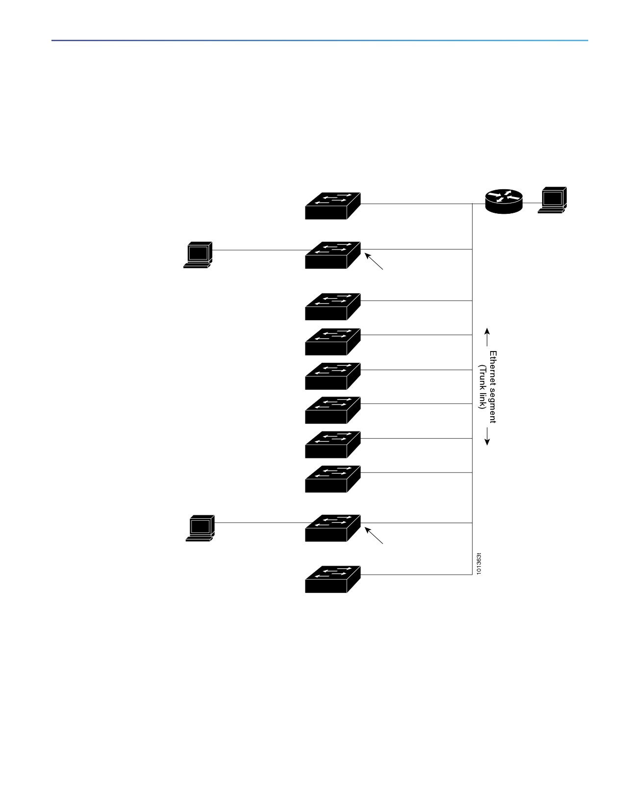
Figure 32 on page 309 shows a network with a VMPS server switch and VMPS client switches with dynamic-access
ports. In this example, these assumptions apply:
The VMPS server and the VMPS client are separate switches.
The Catalyst 6500 series Switch A is the primary VMPS server.
308
Configuring VLANs
Configuration Examples for Configuring VLANs
The Catalyst 6500 series Switch C and Switch J are secondary VMPS servers.
End stations are connected to the clients, Switch B and Switch I.
The database configuration file is stored on the TFTP server with the IP address 172.20.22.7.
Figure
32
Dynamic Port VLAN Membership Configuration
TFTP server
Catalyst 6500 series switch A
Primary VMPS
Router
Server 1
172.20.26.150
172.20.22.7
Client switch B
Dynamic-access port
End
station 1
172.20.26.151
Trunk port
Switch C
Catalyst 6500 series
172.20.26.152
Secondary VMPS
Server 2
172.20.26.153
Switch D
172.20.26.154
Switch E
172.20.26.155
Switch F
172.20.26.156
Switch G
172.20.26.157
Switch H
Client switch I
Dynamic-access port
End
station 2
172.20.26.158
Trunk port
172.20.26.159
Catalyst 6500 series
Secondary VMPS
Switch J
Server 3
Configuring a VLAN: Example
This example shows how to create Ethernet VLAN 20, name it test20, and add it to the VLAN database:
Switch# configure terminal
Switch(config)# vlan 20
Switch(config-vlan)# name test20
Switch(config-vlan)# end
309
Configuring VLANs
Additional References
Configuring an Access Port in a VLAN: Example
This example shows how to configure a port as an access port in VLAN 2:
Switch# configure terminal
Enter configuration commands, one per line. End with CNTL/Z.
Switch(config)# interface GigabitEthernet1/17
Switch(config-if)# switchport mode access
Switch(config-if)# switchport access vlan 2
Switch(config-if)# end
Configuring an Extended-Range VLAN: Example
This example shows how to create a new extended-range VLAN with all default characteristics:
Switch(config)# vtp mode transparent
Switch(config)# vlan 2000
Switch(config-vlan)# end
Switch# copy running-config startup config
Configuring a Trunk Port: Example
This example shows how to configure a port as an IEEE 802.1Q trunk. The example assumes that the neighbor interface
is configured to support IEEE 802.1Q trunking.
Switch(config)# interface GigabitEthernet1/18
Switch(config-if)# switchport mode dynamic desirable
Switch(config-if)# end
Removing a VLAN: Example
This example shows how to remove VLAN 2 from the allowed VLAN list on a port:
Switch(config)# interface GigabitEthernet1/17
Switch(config-if)# switchport trunk allowed vlan remove 2
Switch(config-if)# end
Show VMPS Output: Example
This is an example of output for the show vmps privileged EXEC command:
Switch# show vmps
VQP Client Status:
--------------------
VMPS VQP Version:
1
Reconfirm Interval: 60 min
Server Retry Count: 3
VMPS domain server: 172.20.128.86 (primary, current)
172.20.128.87
Reconfirmation status
---------------------
VMPS Action:
other
Additional References
The following sections provide references related to switch administration:
310
Configuring VLANs
Additional References
Related Documents
Related Topic
Document Title
Cisco IOS basic commands
Cisco IOS Configuration Fundamentals Command Reference
Standards
Standards
Title
No new or modified standards are supported by this
—
feature, and support for existing standards has not
been modified by this feature.
MIBs
MIBs
MIBs Link
—
To locate and download MIBs using Cisco IOS XR software, use the
Cisco MIB Locator found at the following URL and choose a platform
under the Cisco Access Products menu:
RFCs
RFCs
Title
No new or modified RFCs are supported by this
—
feature, and support for existing RFCs has not been
modified by this feature.
311
Configuring VLANs
Additional References
312
Configuring VTP
Prerequisites for Configuring VTP
When you configure VTP, you must configure a trunk port so that the switch can send and receive VTP
advertisements to and from other switches in the domain.
Before adding a VTP client switch to a VTP domain, always verify that its VTP configuration revision number is lower
than the configuration revision number of the other switches in the VTP domain. Switches in a VTP domain always
use the VLAN configuration of the switch with the highest VTP configuration revision number. If you add a switch that
has a revision number higher than the revision number in the VTP domain, it can erase all VLAN information from the
VTP server and VTP domain. See Adding a VTP Client Switch to a VTP Domain, page 323 for the procedure for
verifying and resetting the VTP configuration revision number.
Restrictions for Configuring VTP
VTP version 1 and VTP version 2 are not interoperable on switches in the same VTP domain. Do not enable VTP
version 2 unless every switch in the VTP domain supports version 2.
In VTP versions 1 and 2, when you configure extended-range VLANs on the switch, the switch must be in VTP
transparent mode. VTP version 3 also supports creating extended-range VLANs in client or server mode.
Information About Configuring VTP
VTP
A VLAN Trunking Protocol (VTP) is a Layer 2 messaging protocol that maintains VLAN configuration consistency by
managing the addition, deletion, and renaming of VLANs on a network-wide basis. VTP minimizes misconfigurations and
configuration inconsistencies that can cause several problems, such as duplicate VLAN names, incorrect VLAN-type
specifications, and security violations.
Before you create VLANs, you must decide whether to use VTP in your network. Using VTP, you can make configuration
changes centrally on one or more switches and have those changes automatically communicated to all the other switches
in the network. Without VTP, you cannot send information about VLANs to other switches.
VTP is designed to work in an environment where updates are made on a single switch and are sent through VTP to other
switches in the domain. It does not work well in a situation where multiple updates to the VLAN database occur
simultaneously on switches in the same domain, which would result in an inconsistency in the VLAN database.
The switch supports 1005 VLANs, but the number of configured features affects the usage of the switch hardware. If the
switch is notified by VTP of a new VLAN and the switch is already using the maximum available hardware resources, it
sends a message that there are not enough hardware resources available and shuts down the VLAN. The output of the
show vlan user EXEC command shows the VLAN in a suspended state.
313
Configuring VTP
Information About Configuring VTP
VTP version 1 and version 2 support only normal-range VLANs (VLAN IDs 1 to 1005). VTP version 3 supports the entire
VLAN range (VLANs 1 to 4096). Extended range VLANs (VLANs 1006 to 4096) are supported only in VTP version 3. You
cannot convert from VTP version 3 to VTP version 2 if extended VLANs are configured in the domain.
VTP Domain
A VTP domain (also called a VLAN management domain) consists of one switch or several interconnected switches under
the same administrative responsibility sharing the same VTP domain name. A switch can be in only one VTP domain. You
make global VLAN configuration changes for the domain.
By default, the switch is in the VTP no-management-domain state until it receives an advertisement for a domain over a
trunk link (a link that carries the traffic of multiple VLANs) or until you configure a domain name. Until the management
domain name is specified or learned, you cannot create or modify VLANs on a VTP server, and VLAN information is not
propagated over the network.
If the switch receives a VTP advertisement over a trunk link, it inherits the management domain name and the VTP
configuration revision number. The switch then ignores advertisements with a different domain name or an earlier
configuration revision number.
When you make a change to the VLAN configuration on a VTP server, the change is propagated to all switches in the VTP
domain. VTP advertisements are sent over all IEEE trunk connections, including IEEE 802.1Q. VTP dynamically maps
VLANs with unique names and internal index associates across multiple LAN types. Mapping eliminates excessive device
administration required from network administrators.
If you configure a switch for VTP transparent mode, you can create and modify VLANs, but the changes are not sent to
other switches in the domain, and they affect only the individual switch. However, configuration changes made when the
switch is in this mode are saved in the switch running configuration and can be saved to the switch startup configuration
file.
For domain name and password configuration guidelines, see VTP Configuration Guidelines, page 320.
314

Configuring VTP
Information About Configuring VTP
VTP Modes
Table 36
VTP Modes
VTP Mode
Description
VTP server
In VTP server mode, you can create, modify, and delete VLANs, and specify other configuration parameters
(such as the VTP version) for the entire VTP domain. VTP servers advertise their VLAN configurations to
other switches in the same VTP domain and synchronize their VLAN configurations with other switches
based on advertisements received over trunk links.
VTP server is the default mode.
Note: In VTP server mode, VLAN configurations are saved in NVRAM. If the switch detects a failure while
writing a configuration to NVRAM, VTP mode automatically changes from server mode to client mode. If
this happens, the switch cannot be returned to VTP server mode until the NVRAM is functioning.
VTP client
A VTP client behaves like a VTP server and transmits and receives VTP updates on its trunks, but you
cannot create, change, or delete VLANs on a VTP client. VLANs are configured on another switch in the
domain that is in server mode.
In VTP versions 1 and 2, in VTP client mode, VLAN configurations are not saved in NVRAM. In VTP version
3, VLAN configurations are saved in NVRAM in client mode.
VTP transparent
VTP transparent switches do not participate in VTP. A VTP transparent switch does not advertise its VLAN
configuration and does not synchronize its VLAN configuration based on received advertisements.
However, in VTP version 2 or version 3, transparent switches do forward VTP advertisements that they
receive from other switches through their trunk interfaces. You can create, modify, and delete VLANs on a
switch in VTP transparent mode.
In VTP versions 1 and 2, the switch must be in VTP transparent mode when you create extended-range
VLANs. VTP version 3 also supports creating extended-range VLANs in client or server mode.
When the switch is in VTP transparent mode, the VTP and VLAN configurations are saved in NVRAM, but
they are not advertised to other switches. In this mode, VTP mode and domain name are saved in the
switch running configuration, and you can save this information in the switch startup configuration file by
using the copy running-config startup-config privileged EXEC command.
VTP off
A switch in VTP off mode functions in the same manner as a VTP transparent switch, except that it does
not forward VTP advertisements on trunks.
VTP Mode Guidelines
For VTP version 1 and version 2, if extended-range VLANs are configured on the switch, you cannot change VTP
mode to client or server. You receive an error message, and the configuration is not allowed. VTP version 1 and
version 2 do not propagate configuration information for extended range VLANs (VLANs 1006 to 4096). You must
manually configure these VLANs on each device.
Note: For VTP version 1 and 2, before you create extended-range VLANs (VLAN IDs 1006 to 4096), you must set
VTP mode to transparent by using the vtp mode transparent global configuration command. Save this configuration
to the startup configuration so that the switch starts in VTP transparent mode. Otherwise, you lose the
extended-range VLAN configuration if the switch resets and boots up in VTP server mode (the default).
VTP version 3 supports extended-range VLANs. If extended VLANs are configured, you cannot convert from VTP
version 3 to VTP version 2.
If you configure the switch for VTP client mode, the switch does not create the VLAN database file (vlan.dat). If the
switch is then powered off, it resets the VTP configuration to the default. To keep the VTP configuration with VTP
client mode after the switch restarts, you must first configure the VTP domain name before the VTP mode.
315
Configuring VTP
Information About Configuring VTP
When a switch is in VTP server mode, you can change the VLAN configuration and have it propagated throughout
the network.
When a switch is in VTP client mode, you cannot change its VLAN configuration. The client switch receives VTP
updates from a VTP server in the VTP domain and then modifies its configuration accordingly.
When you configure the switch for VTP transparent mode, VTP is disabled on the switch. The switch does not send
VTP updates and does not act on VTP updates received from other switches. However, a VTP transparent switch
running VTP version 2 does forward received VTP advertisements on its trunk links.
VTP off mode is the same as VTP transparent mode except that VTP advertisements are not forwarded.
Caution: If all switches are operating in VTP client mode, do not configure a VTP domain name. If you do, it is
impossible to make changes to the VLAN configuration of that domain. Therefore, make sure you configure at least
one switch as a VTP server.
VTP Advertisements
Each switch in the VTP domain sends periodic global configuration advertisements from each trunk port to a reserved
multicast address. Neighboring switches receive these advertisements and update their VTP and VLAN configurations
as necessary.
VTP advertisements distribute this global domain information:
VTP domain name
VTP configuration revision number
Update identity and update timestamp
MD5 digest VLAN configuration, including maximum transmission unit (MTU) size for each VLAN
Frame format
VTP advertisements distribute this VLAN information for each configured VLAN:
VLAN IDs (IEEE 802.1Q)
VLAN name
VLAN type
VLAN state
Additional VLAN configuration information specific to the VLAN type
In VTP version 3, VTP advertisements also include the primary server ID, an instance number, and a start index.
VTP Version 2
If you use VTP in your network, you must decide which version of VTP to use. By default, VTP operates in version 1.
VTP version 2 supports these features that are not supported in version 1:
Token Ring support—VTP version 2 supports Token Ring Bridge Relay Function (TrBRF) and Token Ring Concentrator
Relay Function (TrCRF) VLANs. For more information about Token Ring VLANs, see Normal-Range VLANs, page 291.
Unrecognized Type-Length-Value (TLV) support—A VTP server or client propagates configuration changes to its
other trunks, even for TLVs it is not able to parse. The unrecognized TLV is saved in NVRAM when the switch is
operating in VTP server mode.
316
Configuring VTP
Information About Configuring VTP
Version-Dependent Transparent Mode—In VTP version 1, a VTP transparent switch inspects VTP messages for the
domain name and version and forwards a message only if the version and domain name match. Although VTP version
2 supports only one domain, a VTP version 2 transparent switch forwards a message only when the domain name
matches.
Consistency Checks—In VTP version 2, VLAN consistency checks (such as VLAN names and values) are performed
only when you enter new information through the CLI or SNMP. Consistency checks are not performed when new
information is obtained from a VTP message or when information is read from NVRAM. If the MD5 digest on a
received VTP message is correct, its information is accepted.
VTP Version 3
VTP version 3 supports these features that are not supported in version 1 or version 2:
Enhanced authentication—You can configure the authentication as hidden or secret. When hidden, the secret key
from the password string is saved in the VLAN database file, but it does not appear in plain text in the configuration.
Instead, the key associated with the password is saved in hexadecimal format in the running configuration. You must
reenter the password if you enter a takeover command in the domain. When you enter the secret keyword, you can
directly configure the password secret key.
Support for extended range VLAN (VLANs 1006 to 4096) database propagation. VTP versions 1 and 2 propagate
only VLANs 1 to 1005. If extended VLANs are configured, you cannot convert from VTP version 3 to version 1 or 2.
VTP pruning still applies only to VLANs 1 to 1005, and VLANs 1002 to 1005 are still reserved and cannot be
modified.
Support for any database in a domain. In addition to propagating VTP information, version 3 can propagate Multiple
Spanning Tree (MST) protocol database information. A separate instance of the VTP protocol runs for each
application that uses VTP.
VTP primary server and VTP secondary servers. A VTP primary server updates the database information and sends
updates that are honored by all devices in the system. A VTP secondary server can only back up the updated VTP
configurations received from the primary server to its NVRAM.
By default, all devices come up as secondary servers. You can enter the vtp primary privileged EXEC command to
specify a primary server. Primary server status is only needed for database updates when the administrator issues
a takeover message in the domain. You can have a working VTP domain without any primary servers. Primary server
status is lost if the device reloads or domain parameters change, even when a password is configured on the switch.
The option to turn VTP on or off on a per-trunk (per-port) basis. You can enable or disable VTP per port by entering
the [no] vtp interface configuration command. When you disable VTP on trunking ports, all VTP instances for that
port are disabled. You cannot set VTP to off for the MST database and on for the VLAN database on the same port.
When you globally set VTP mode to off, it applies to all the trunking ports in the system. However, you can specify
on or off on a per-VTP instance basis. For example, you can configure the switch as a VTP server for the VLAN
database but with VTP off for the MST database.
VTP Version Guidelines
Follow these guidelines when deciding which VTP version to implement:
All switches in a VTP domain must have the same domain name, but they do not need to run the same VTP version.
A VTP version 2-capable switch can operate in the same VTP domain as a switch running VTP version 1 if version
2 is disabled on the version 2-capable switch (version 2 is disabled by default).
If a switch running VTP version 1 but capable of running VTP version 2 receives VTP version 3 advertisements, it
automatically moves to VTP version 2.
317
Configuring VTP
Information About Configuring VTP
If a switch running VTP version 3 is connected to a switch running VTP version 1, the VTP version 1 switch moves
to VTP version 2, and the VTP version 3 switch sends scaled-down versions of the VTP packets so that the VTP
version 2 switch can update its database.
A switch running VTP version 3 cannot move to version 1 or 2 if it has extended VLANs.
Do not enable VTP version 2 on a switch unless all of the switches in the same VTP domain are version-2-capable.
When you enable version 2 on a switch, all of the version-2-capable switches in the domain enable version 2. If there
is a version 1-only switch, it does not exchange VTP information with switches that have version 2 enabled.
We recommend placing VTP version 1 and 2 switches at the edge of the network because they do not forward VTP
version 3 advertisements.
If there are TrBRF and TrCRF Token Ring networks in your environment, you must enable VTP version 2 or version 3
for Token Ring VLAN switching to function properly. To run Token Ring and Token Ring-Net, disable VTP version 2.
VTP version 1 and version 2 do not propagate configuration information for extended range VLANs (VLANs 1006 to
4096). You must configure these VLANs manually on each device. VTP version 3 supports extended-range VLANs.
You cannot convert from VTP version 3 to VTP version 2 if extended VLANs are configured.
When a VTP version 3 device trunk port receives messages from a VTP version 2 device, it sends a scaled-down
version of the VLAN database on that particular trunk in VTP version 2 format. A VTP version 3 device does not send
VTP version 2-formatted packets on a trunk unless it first receives VTP version 2 packets on that trunk port.
When a VTP version 3 device detects a VTP version 2 device on a trunk port, it continues to send VTP version 3
packets, in addition to VTP version 2 packets, to allow both kinds of neighbors to coexist on the same trunk.
A VTP version 3 device does not accept configuration information from a VTP version 2 or version 1 device.
Two VTP version 3 regions can only communicate in transparent mode over a VTP version 1 or version 2 region.
Devices that are only VTP version 1 capable cannot interoperate with VTP version 3 devices.
VTP version 2 and version 3 are disabled by default.
When you enable VTP version 2 on a switch, every VTP version 2-capable switch in the VTP domain enables
version 2. To enable VTP version 3, you must manually configure it on each switch.
With VTP versions 1 and 2, you can configure the version only on switches in VTP server or transparent mode. If a
switch is running VTP version 3, you can change to version 2 when the switch is in client mode if no extended VLANs
exist, no private VLANs exist, and no hidden password was configured.
Caution: In VTP version 3, both the primary and secondary servers can exist on an instance in the domain.
VTP Pruning
VTP pruning increases network available bandwidth by restricting flooded traffic to those trunk links that the traffic must
use to reach the destination devices. Without VTP pruning, a switch floods broadcast, multicast, and unknown unicast
traffic across all trunk links within a VTP domain even though receiving switches might discard them. VTP pruning is
disabled by default.
VTP pruning blocks unneeded flooded traffic to VLANs on trunk ports that are included in the pruning-eligible list. Only
VLANs included in the pruning-eligible list can be pruned. By default, VLANs 2 through 1001 are pruning eligible switch
trunk ports. If the VLANs are configured as pruning-ineligible, the flooding continues. VTP pruning is supported in all VTP
versions.
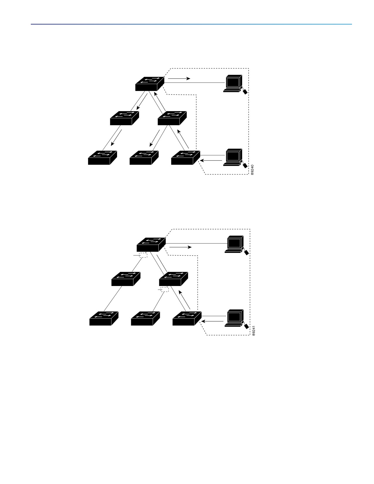
Figure 33 on page 319 shows a switched network without VTP pruning enabled. Port 1 on Switch A and Port 2 on Switch
D are assigned to the Red VLAN. If a broadcast is sent from the host connected to Switch A, Switch A floods the
broadcast and every switch in the network receives it, even though Switches C, E, and F have no ports in the Red VLAN.
318
Configuring VTP
Information About Configuring VTP
Figure 33
Flooding Traffic without VTP Pruning
Switch D
Port 2
Switch E
Switch B
Red
VLAN
Port 1
Switch F
Switch C
Switch A
Figure 34 on page 319 shows a switched network with VTP pruning enabled. The broadcast traffic from Switch A is not
forwarded to Switches C, E, and F because traffic for the Red VLAN has been pruned on the links shown (Port 5 on Switch
B and Port 4 on Switch D).
Figure 34
Optimized Flooded Traffic with VTP Pruning
Switch D
Port 2
Flooded traffic
is pruned.
Port
4
Switch B
Red
VLAN
Switch E
Flooded traffic
is pruned.
Port
5
Port 1
Switch F
Switch C
Switch A
With VTP versions 1 and 2, enabling VTP pruning on a VTP server enables pruning for the entire management domain.
Making VLANs pruning-eligible or pruning-ineligible affects pruning eligibility for those VLANs on that trunk only (not on
all switches in the VTP domain). In VTP version 3, you must manually enable pruning on each switch in the domain.
See Enabling VTP Pruning, page 323. VTP pruning takes effect several seconds after you enable it. VTP pruning does
not prune traffic from VLANs that are pruning-ineligible. VLAN 1 and VLANs 1002 to 1005 are always pruning-ineligible;
traffic from these VLANs cannot be pruned. Extended-range VLANs (VLAN IDs higher than 1005) are also
pruning-ineligible.
VTP pruning is not designed to function in VTP transparent mode. If one or more switches in the network are in VTP
transparent mode, you should do one of these:
Turn off VTP pruning in the entire network.
319

Configuring VTP
Information About Configuring VTP
Turn off VTP pruning by making all VLANs on the trunk of the switch upstream to the VTP transparent switch pruning
ineligible.
To configure VTP pruning on an interface, use the switchport trunk pruning vlan interface configuration command. VTP
pruning operates when an interface is trunking. You can set VLAN pruning-eligibility, whether or not VTP pruning is
enabled for the VTP domain, whether or not any given VLAN exists, and whether or not the interface is currently trunking.
Default VTP Settings
Feature
Default Setting
VTP domain name
Null.
VTP mode (VTP version 1 and version 2)
Server.
VTP mode (VTP version 3)
The mode is the same as the mode in VTP version 1 or 2 before
conversion to version 3.
VTP version
Version 1.
MST database mode
Transparent.
VTP version 3 server type
Secondary.
VTP password
None.
VTP pruning
Disabled.
VTP Configuration Guidelines
You use the vtp global configuration command to set the VTP password, the version, the VTP filename, the interface
providing updated VTP information, the domain name, and the mode, and to disable or enable pruning. The VTP
information is saved in the VTP VLAN database. When VTP mode is transparent, the VTP domain name and mode are
also saved in the switch running configuration file, and you can save it in the switch startup configuration file by entering
the copy running-config startup-config privileged EXEC command. You must use this command if you want to save
VTP mode as transparent if the switch resets.
When you save VTP information in the switch startup configuration file and restart the switch, the configuration is selected
as follows:
If the VTP mode is transparent in both the startup configuration and the VLAN database and the VTP domain name
from the VLAN database matches that in the startup configuration file, the VLAN database is ignored (cleared). The
VTP and VLAN configurations in the startup configuration file are used. The VLAN database revision number remains
unchanged in the VLAN database.
If the VTP mode or the domain name in the startup configuration do not match the VLAN database, the domain name
and the VTP mode and configuration for the first 1005 VLANs use the VLAN database information.
Domain Names
When configuring VTP for the first time, you must always assign a domain name. You must configure all switches in the
VTP domain with the same domain name. Switches in VTP transparent mode do not exchange VTP messages with other
switches, and you do not need to configure a VTP domain name for them.
Note: If NVRAM and DRAM storage is sufficient, all switches in a VTP domain should be in VTP server mode.
Caution: Do not configure a VTP domain if all switches are operating in VTP client mode. If you configure the domain,
it is impossible to make changes to the VLAN configuration of that domain. Make sure that you configure at least
one switch in the VTP domain for VTP server mode.
320

Configuring VTP
How to Configure VTP
Passwords
You can configure a password for the VTP domain, but it is not required. If you do configure a domain password, all
domain switches must share the same password and you must configure the password on each switch in the
management domain. Switches without a password or with the wrong password reject VTP advertisements.
If you configure a VTP password for a domain, a switch that is booted without a VTP configuration does not accept VTP
advertisements until you configure it with the correct password. After the configuration, the switch accepts the next VTP
advertisement that uses the same password and domain name in the advertisement.
If you are adding a new switch to an existing network with VTP capability, the new switch learns the domain name only
after the applicable password has been configured on it.
Caution: When you configure a VTP domain password, the management domain does not function properly if you
do not assign a management domain password to each switch in the domain.
Adding a VTP Client Switch to a VTP Domain
Before adding a VTP client to a VTP domain, always verify that its VTP configuration revision number is lower than the
configuration revision number of the other switches in the VTP domain. Switches in a VTP domain always use the VLAN
configuration of the switch with the highest VTP configuration revision number. With VTP versions 1 and 2, adding a
switch that has a revision number higher than the revision number in the VTP domain can erase all VLAN information from
the VTP server and VTP domain. With VTP version 3, the VLAN information is not erased.
How to Configure VTP
Configuring VTP Domain and Parameters
Before You Begin
You should configure the VTP domain before configuring other VTP parameters.
Command
Purpose
1.
configure terminal
Enters global configuration mode.
2.
vtp domain domain-name
Configures the VTP administrative-domain name. The name can be 1 to 32
characters. All switches operating in VTP server or client mode under the
same administrative responsibility must be configured with the same
domain name.
This command is optional for modes other than server mode. VTP server
mode requires a domain name. If the switch has a trunk connection to a
VTP domain, the switch learns the domain name from the VTP server in the
domain.
3.
vtp mode {client | server |
Configures the switch for VTP mode (client, server, transparent, or off).
transparent | off} {vlan | mst |
unknown}
(Optional) Database parameters:
vlan—The VLAN database is the default if none are configured.
mst—The multiple spanning tree (MST) database.
unknown—An unknown database type.
321

Configuring VTP
How to Configure VTP
Command
Purpose
4.
vtp password password
(Optional) Sets the password for the VTP domain. The password can be 8
to 64 characters. If you configure a VTP password, the VTP domain does
not function properly if you do not assign the same password to each
switch in the domain.
See Configuring a VTP Version 3 Password, page 322 for options available
with VTP version 3.
1.
vtp primary-server [vlan | mst]
(Optional) Changes the operational state of a switch from a secondary
[force]
server (the default) to a primary server and advertise the configuration to
the domain. If the switch password is configured as hidden, you are
prompted to reenter the password.
vlan—Selects the VLAN database as the takeover feature. This is the
default.
mst—Selects the multiple spanning tree (MST) database as the
takeover feature.
force—Overwrites the configuration of any conflicting servers. If you do
not enter force, you are prompted for confirmation before the
takeover.
2.
end
Returns to privileged EXEC mode.
3.
show vtp status
Verifies your entries in the VTP Operating Mode and the VTP Domain Name
fields of the display.
4.
copy running-config startup-config
(Optional) Saves the configuration in the startup configuration file.
Note: Only VTP mode and domain name are saved in the switch running
configuration and can be copied to the startup configuration file.
Configuring a VTP Version 3 Password
Command
Purpose
1.
configure terminal
Enters global configuration mode.
2.
vtp password password [hidden |
(Optional) Sets the password for the VTP domain. The password can be 8
secret]
to 64 characters.
(Optional) hidden—Ensures that the secret key generated from the
password string is saved in the nvam:vlan.dat file. If you configure a
takeover by configuring a VTP primary server, you are prompted to
reenter the password.
(Optional) secret—Directly configures the password. The secret
password must contain 32 hexadecimal characters.
3.
end
Returns to privileged EXEC mode.
4.
show vtp password
Verifies your entries.
322

Configuring VTP
How to Configure VTP
Enabling the VTP Version
Command
Purpose
1.
configure terminal
Enters global configuration mode.
2.
vtp version {1 | 2 | 3}
Enables the VTP version on the switch. The default is VTP version 1.
3.
end
Returns to privileged EXEC mode.
4.
show vtp status
Verifies that the configured VTP version is enabled.
5.
copy running-config
(Optional) Saves the configuration in the startup configuration file.
startup-config
Enabling VTP Pruning
Command
Purpose
1.
configure terminal
Enters global configuration mode.
2.
vtp pruning
Enables pruning in the VTP administrative domain.
By default, pruning is disabled. You need to enable pruning on only one switch
in VTP server mode.
3.
end
Returns to privileged EXEC mode.
4.
show vtp status
Verifies your entries in the VTP Pruning Mode field of the display.
Configuring VTP on a Per-Port Basis
Command
Purpose
1.
configure terminal
Enters global configuration mode.
2.
interface interface-id
Identifies an interface, and enters interface configuration mode.
3.
vtp
Enables VTP on the specified port.
4.
end
Returns to privileged EXEC mode.
5.
show running-config interface
Verifies the change to the port.
interface-id
6.
show vtp status
Verifies the configuration.
Adding a VTP Client Switch to a VTP Domain
Before You Begin
Before adding a VTP client to a VTP domain, always verify that its VTP configuration revision number is lower than the
configuration revision number of the other switches in the VTP domain. Switches in a VTP domain always use the VLAN
configuration of the switch with the highest VTP configuration revision number. With VTP versions 1 and 2, adding a
switch that has a revision number higher than the revision number in the VTP domain can erase all VLAN information from
the VTP server and VTP domain. With VTP version 3, the VLAN information is not erased.
323

Configuring VTP
Monitoring and Maintaining VTP
Command
Purpose
1.
show vtp status
Checks the VTP configuration revision number.
If the number is 0, add the switch to the VTP domain.
If the number is greater than 0, follow these steps:
a. Write down the domain name.
b. Write down the configuration revision number.
c. Continue with the next steps to reset the switch configuration revision
number.
2.
configure terminal
Enters global configuration mode.
3.
vtp domain domain-name
Changes the domain name from the original one displayed in Step 1 to a new name.
4.
end
Updates VLAN information on the switch and resets configuration revision number
to 0.
5.
show vtp status
Verifies that the configuration revision number has been reset to 0.
6.
configure terminal
Enters global configuration mode.
7.
vtp domain domain-name
Enters the original domain name on the switch.
8.
end
Returns to privileged EXEC mode.
9.
show vtp status
(Optional) Verifies that the domain name is the same as in Step 1 and that the
configuration revision number is 0.
10.
After resetting the
configuration revision
number, add the switch to the
VTP domain.
Monitoring and Maintaining VTP
Command
Purpose
show vtp counters
Displays counters about VTP messages that have been sent
and received.
show vtp devices [conflict]
Displays information about all VTP version 3 devices in the
domain. Conflicts are VTP version 3 devices with conflicting
primary servers. The show vtp devices command does not
display information when the switch is in transparent or off
mode.
show vtp interface [interface-id]
Displays VTP status and configuration for all interfaces or the
specified interface.
show vtp password
Displays the VTP password. The form of the password
displayed depends on whether or not the hidden keyword
was entered and if encryption is enabled on the switch.
show vtp status
Displays the VTP switch configuration information.
324
Configuring VTP
Configuration Examples for Configuring VTP
Configuration Examples for Configuring VTP
Configuring a VTP Server: Example
This example shows how to configure the switch as a VTP server with the domain name eng_group and the password
mypassword:
Switch(config)# vtp domain eng_group
Setting VTP domain name to eng_group.
Switch(config)# vtp mode server
Setting device to VTP Server mode for VLANS.
Switch(config)# vtp password mypassword
Setting device VLAN database password to mypassword.
Switch(config)# end
Configuring a Hidden VTP Password: Example
This example shows how to configure a hidden password and how it appears:
Switch(config)# vtp password mypassword hidden
Generating the secret associated to the password.
Switch(config)# end
Switch# show vtp password
VTP password: 89914640C8D90868B6A0D8103847A733
Configuring a VTP Version 3 Primary Server: Example
This example shows how to configure a switch as the primary server for the VLAN database (the default) when a hidden
or secret password was configured:
Switch# vtp primary vlan
Enter VTP password: mypassword
This switch is becoming Primary server for vlan feature in the VTP domain
VTP Database Conf Switch ID
Primary Server Revision System Name
------------ ---- -------------- -------------- -------- --------------------
VLANDB
Yes
00d0.00b8.1400=00d0.00b8.1400 1
stp7
Do you want to continue (y/n) [n]? y
Additional References for Configuring VTP
The following sections provide references related to switch administration:
325

Configuring VTP
Additional References for Configuring VTP
Related Documents
Related Topic
Document Title
Cisco IOS basic commands
Cisco IOS Configuration Fundamentals Command Reference
VLAN configuration
Configuring VLANs, page 289
Standards
Standards
Title
No new or modified standards are supported by this
—
feature, and support for existing standards has not
been modified by this feature.
MIBs
MIBs
MIBs Link
—
To locate and download MIBs using Cisco IOS XR software, use the
Cisco MIB Locator found at the following URL and choose a platform
under the Cisco Access Products menu:
RFCs
RFCs
Title
No new or modified RFCs are supported by this
—
feature, and support for existing RFCs has not been
modified by this feature.
326
Configuring Voice VLAN
Information About Configuring Voice VLAN
Voice VLAN
The voice VLAN feature enables access ports to carry IP voice traffic from an IP phone. When the switch is connected
to a Cisco 7960 IP Phone, the phone sends voice traffic with Layer 3 IP precedence and Layer 2 class of service (CoS)
values, which are both set to 5 by default. Because the sound quality of a Cisco IP phone call can deteriorate if the data
is unevenly sent, the switch supports quality of service (QoS) based on IEEE 802.1p CoS. QoS uses classification and
scheduling to send network traffic from the switch in a predictable manner. Voice VLAN is referred to as an auxiliary VLAN
in some switch documentation.
The Cisco 7960 IP Phone is a configurable device, and you can configure it to forward traffic with an IEEE 802.1p priority.
You can configure the switch to trust or override the traffic priority assigned by a Cisco IP phone.
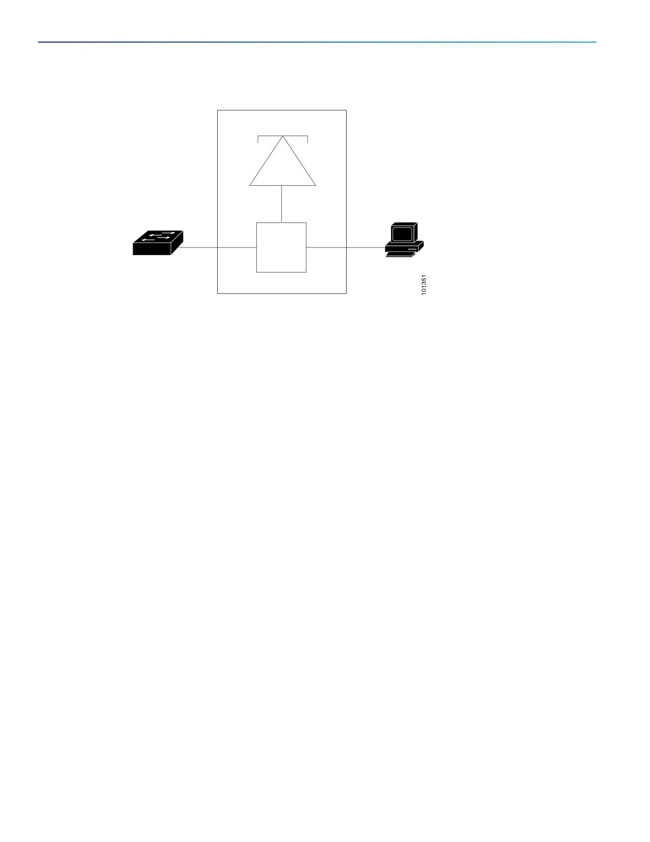
The Cisco IP phone contains an integrated three-port 10/100 switch as shown in Figure 35 on page 328. The ports
provide dedicated connections to these devices:
Port 1 connects to the switch or other voice-over-IP (VoIP) device.
Port 2 is an internal 10/100 interface that carries the IP phone traffic.
Port 3 (access port) connects to a PC or other device.
327
Configuring Voice VLAN
Information About Configuring Voice VLAN
Figure 35
Cisco 7960 IP Phone Connected to a Switch
Cisco IP Phone 7960
Phone
ASIC
P2
PC
P1
3-port
P3
switch
Access
port
Cisco IP Phone Voice Traffic
You can configure an access port with an attached Cisco IP phone to use one VLAN for voice traffic and another VLAN
for data traffic from a device attached to the phone. You can configure access ports on the switch to send Cisco
Discovery Protocol (CDP) packets that instruct an attached phone to send voice traffic to the switch in any of these ways:
In the voice VLAN tagged with a Layer 2 CoS priority value
In the access VLAN tagged with a Layer 2 CoS priority value
In the access VLAN, untagged (no Layer 2 CoS priority value)
Note: In all configurations, the voice traffic carries a Layer 3 IP precedence value (the default is 5 for voice traffic and 3
for voice control traffic).
You can configure a port connected to the Cisco IP phone to send CDP packets to the phone to configure the way in
which the phone sends voice traffic. The phone can carry voice traffic in IEEE 802.1Q frames for a specified voice VLAN
with a Layer 2 CoS value. It can use IEEE 802.1p priority tagging to give voice traffic a higher priority and forward all voice
traffic through the native (access) VLAN. The Cisco IP phone can also send untagged voice traffic or use its own
configuration to send voice traffic in the access VLAN. In all configurations, the voice traffic carries a Layer 3 IP
precedence value (the default is 5).
Cisco IP Phone Data Traffic
The switch can also process tagged data traffic (traffic in IEEE 802.1Q or IEEE 802.1p frame types) from the device
attached to the access port on the Cisco IP phone (see Figure 35 on page 328). You can configure Layer 2 access ports
on the switch to send CDP packets that instruct the attached phone to configure the phone access port in one of these
modes:
In trusted mode, all traffic received through the access port on the Cisco IP phone passes through the phone
unchanged.
In untrusted mode, all traffic in IEEE 802.1Q or IEEE 802.1p frames received through the access port on the Cisco IP
phone receive a configured Layer 2 CoS value. The default Layer 2 CoS value is 0. Untrusted mode is the default.
Note: Untagged traffic from the device attached to the Cisco IP phone passes through the phone unchanged, regardless
of the trust state of the access port on the phone.
328
Configuring Voice VLAN
Information About Configuring Voice VLAN
Default Voice VLAN Configuration
The voice VLAN feature is disabled by default.
When the voice VLAN feature is enabled, all untagged traffic is sent according to the default CoS priority of the port.
The CoS value is not trusted for IEEE 802.1p or IEEE 802.1Q tagged traffic.
Voice VLAN Configuration Guidelines
Voice VLAN configuration is only supported on switch access ports; voice VLAN configuration is not supported on
trunk ports.
Note: Trunk ports can carry any number of voice VLANs, similar to regular VLANs. The configuration of voice VLANs
is not required on trunk ports.
The voice VLAN should be present and active on the switch for the IP phone to correctly communicate on the voice
VLAN. Use the show vlan privileged EXEC command to see if the VLAN is present (listed in the display).
Before you enable voice VLAN, we recommend that you enable QoS on the switch. If you use the auto-QoS feature,
these settings are automatically configured. For more information, see Configuring QoS, page 613
You must enable CDP on the switch port connected to the Cisco IP phone to send the configuration to the phone.
(CDP is globally enabled by default on all switch interfaces.)
The Port Fast feature is automatically enabled when voice VLAN is configured. When you disable voice VLAN, the
Port Fast feature is not automatically disabled.
If the Cisco IP phone and a device attached to the phone are in the same VLAN, they must be in the same IP subnet.
These conditions indicate that they are in the same VLAN:
— They both use IEEE 802.1p or untagged frames.
— The Cisco IP phone uses IEEE 802.1p frames, and the device uses untagged frames.
— The Cisco IP phone uses untagged frames, and the device uses IEEE 802.1p frames.
— The Cisco IP phone uses IEEE 802.1Q frames, and the voice VLAN is the same as the access VLAN.
The Cisco IP phone and a device attached to the phone cannot communicate if they are in the same VLAN and subnet
but use different frame types because traffic in the same subnet is not routed (routing would eliminate the frame
type difference).
You cannot configure static secure MAC addresses in the voice VLAN.
Voice VLAN ports can also be these port types:
— Dynamic access port.
— IEEE 802.1x authenticated port. See Configuring IEEE 802.1x Port-Based Authentication, page 189 for more
information.
If you enable IEEE 802.1x on an access port on which a voice VLAN is configured and to which a Cisco IP phone
is connected, the phone loses connectivity to the switch for up to 30 seconds.
— Protected port.
— A source or destination port for a SPAN or RSPAN session.
— Secure port.
329

Configuring Voice VLAN
How to Configure Voice VLAN
When you enable port security on an interface that is also configured with a voice VLAN, you must set the
maximum allowed secure addresses on the port to two plus the maximum number of secure addresses allowed
on the access VLAN. When the port is connected to a Cisco IP phone, the phone requires up to two MAC
addresses. The phone address is learned on the voice VLAN and might also be learned on the access VLAN.
Connecting a PC to the phone requires additional MAC addresses.
Port Connection to a Cisco 7960 IP Phone
Because a Cisco 7960 IP Phone also supports a connection to a PC or other device, a port connecting the switch to a
Cisco IP phone can carry mixed traffic. You can configure a port to decide how the Cisco IP phone carries voice traffic
and data traffic.
Priority of Incoming Data Frames
You can connect a PC or other data device to a Cisco IP phone port. To process tagged data traffic (in IEEE 802.1Q or
IEEE 802.1p frames), you can configure the switch to send CDP packets to instruct the phone how to send data packets
from the device attached to the access port on the Cisco IP phone. The PC can generate packets with an assigned CoS
value. You can configure the phone to not change (trust) or to override (not trust) the priority of frames arriving on the
phone port from connected devices.
How to Configure Voice VLAN
Configuring the Priority of Incoming Data Frames
Command
Purpose
1.
configure terminal
Enters global configuration mode.
2.
interface interface-id
Specifies the interface connected to the Cisco IP phone, and enters interface
configuration mode.
3.
switchport priority extend
Sets the priority of data traffic received from the Cisco IP phone access port:
{cos value | trust}
cos value—Configures the phone to override the priority received from
the PC or the attached device with the specified CoS value. The value is
a number from 0 to 7, with 7 as the highest priority. The default priority
is cos 0.
trust—Configures the phone access port to trust the priority received
from the PC or the attached device.
4.
end
Returns to privileged EXEC mode.
Monitoring and Maintaining Voice VLAN
Command
Purpose
show interfaces interface-id switchport
Verifies your entries.
copy running-config startup-config
Saves your entries in the configuration file.
330
Configuring Voice VLAN
Configuration Examples for Configuring Voice VLAN
Configuration Examples for Configuring Voice VLAN
Configuring the Cisco IP Phone Priority of Incoming Data Frames: Example
This example shows how to configure a port connected to a Cisco IP phone to not change the priority of frames received
from the PC or the attached device:
Switch(config)# interface GigabitEthernet1/17
Switch(config-if)# switchport priority extend trust
Switch(config-if)# end
Additional References for Configuring Voice VLAN
The following sections provide references related to switch administration:
331

Configuring Voice VLAN
Additional References for Configuring Voice VLAN
Related Documents
Related Topic
Document Title
Cisco IOS basic commands
Cisco IOS Configuration Fundamentals Command Reference
QoS configuration
Configuring QoS, page 613
VLAN configuration
Configuring VLANs, page 289
IEEE 802.1x authenticated port configuration
Configuring IEEE 802.1x Port-Based Authentication, page 189
Protected port configuration
“Configuring Protected Ports”
Secure port configuration
“Configuring Port Security”
Standards
Standards
Title
No new or modified standards are supported by this
—
feature, and support for existing standards has not
been modified by this feature.
MIBs
MIBs
MIBs Link
—
To locate and download MIBs using Cisco IOS XR software, use the
Cisco MIB Locator found at the following URL and choose a platform
under the Cisco Access Products menu:
RFCs
RFCs
Title
No new or modified RFCs are supported by this
—
feature, and support for existing RFCs has not been
modified by this feature.
332
Configuring STP
Prerequisites for Configuring STP
When you configure VTP, you must configure a trunk port so that the switch can send and receive VTP advertisements
to and from other switches in the domain.
For more information, see Configuring an Ethernet Interface as a Trunk Port, page 304.
Restrictions for Configuring STP
If you are configuring VTP on a cluster member switch to a VLAN, use the rcommand privileged EXEC command to
log in to the member switch.
In VTP versions 1 and 2, when you configure extended-range VLANs on the switch, the switch must be in VTP
transparent mode. VTP version 3 also supports creating extended-range VLANs in client or server mode.
Information About Configuring STP
This chapter describes how to configure the Spanning Tree Protocol (STP) on port-based VLANs on the switch. The
switch can use either the per-VLAN spanning-tree plus (PVST+) protocol based on the IEEE 802.1D standard and Cisco
proprietary extensions, or the rapid per-VLAN spanning-tree plus (rapid-PVST+) protocol based on the IEEE 802.1w
standard.
STP
STP is a Layer 2 link management protocol that provides path redundancy while preventing loops in the network. For a
Layer 2 Ethernet network to function properly, only one active path can exist between any two stations. Multiple active
paths among end stations cause loops in the network. If a loop exists in the network, end stations might receive duplicate
messages. Switches might also learn end-station MAC addresses on multiple Layer 2 interfaces. These conditions result
in an unstable network. Spanning-tree operation is transparent to end stations, which cannot detect whether they are
connected to a single LAN segment or a switched LAN of multiple segments.
The STP uses a spanning-tree algorithm to select one switch of a redundantly connected network as the root of the
spanning tree. The algorithm calculates the best loop-free path through a switched Layer 2 network by assigning a role
to each port based on the role of the port in the active topology:
Root—A forwarding port elected for the spanning-tree topology
Designated—A forwarding port elected for every switched LAN segment
Alternate—A blocked port providing an alternate path to the root bridge in the spanning tree
Backup—A blocked port in a loopback configuration
The switch that has all of its ports as the designated role or as the backup role is the root switch. The switch that has at
least one of its ports in the designated role is called the designated switch.
333
Configuring STP
Information About Configuring STP
Spanning tree forces redundant data paths into a standby (blocked) state. If a network segment in the spanning tree fails
and a redundant path exists, the spanning-tree algorithm recalculates the spanning-tree topology and activates the
standby path. Switches send and receive spanning-tree frames, called bridge protocol data units (BPDUs), at regular
intervals. The switches do not forward these frames but use them to construct a loop-free path. BPDUs contain
information about the sending switch and its ports, including switch and MAC addresses, switch priority, port priority,
and path cost. Spanning tree uses this information to elect the root switch and root port for the switched network and
the root port and designated port for each switched segment.
When two ports on a switch are part of a loop, the spanning-tree port priority and path cost settings control which port
is put in the forwarding state and which is put in the blocking state. The spanning-tree port priority value represents the
location of a port in the network topology and how well it is located to pass traffic. The path cost value represents the
media speed.
Note: The default is for the switch to send keepalive messages (to ensure the connection is up) only on interfaces that
do not have small form-factor pluggable (SFP) modules. You can use the [no] keepalive interface configuration
command to change the default for an interface.
Spanning-Tree Topology and BPDUs
The stable, active spanning-tree topology of a switched network is controlled by these elements:
The unique bridge ID (switch priority and MAC address) associated with each VLAN on each switch.
The spanning-tree path cost to the root switch.
The port identifier (port priority and MAC address) associated with each Layer 2 interface.
When the switches in a network are powered up, each functions as the root switch. Each switch sends a configuration
BPDU through all of its ports. The BPDUs communicate and compute the spanning-tree topology. Each configuration
BPDU contains this information:
The unique bridge ID of the switch that the sending switch identifies as the root switch
The spanning-tree path cost to the root
The bridge ID of the sending switch
Message age
The identifier of the sending interface
Values for the hello, forward delay, and max-age protocol timers
When a switch receives a configuration BPDU that contains superior information (lower bridge ID, lower path cost, and
so forth), it stores the information for that port. If this BPDU is received on the root port of the switch, the switch also
forwards it with an updated message to all attached LANs for which it is the designated switch.
If a switch receives a configuration BPDU that contains inferior information to that currently stored for that port, it discards
the BPDU. If the switch is a designated switch for the LAN from which the inferior BPDU was received, it sends that LAN
a BPDU containing the up-to-date information stored for that port. In this way, inferior information is discarded, and
superior information is propagated on the network.
A BPDU exchange results in these actions:
One switch in the network is elected as the root switch (the logical center of the spanning-tree topology in a
switched network).
For each VLAN, the switch with the highest switch priority (the lowest numerical priority value) is elected as the root
switch. If all switches are configured with the default priority (32768), the switch with the lowest MAC address in the
VLAN becomes the root switch. The switch priority value occupies the most significant bits of the bridge ID, as shown
in Table 37 on page 335.
334

Configuring STP
Information About Configuring STP
A root port is selected for each switch (except the root switch). This port provides the best path (lowest cost) when
the switch forwards packets to the root switch.
The shortest distance to the root switch is calculated for each switch based on the path cost.
A designated switch for each LAN segment is selected. The designated switch incurs the lowest path cost when
forwarding packets from that LAN to the root switch. The port through which the designated switch is attached to
the LAN is called the designated port.
All paths that are not needed to reach the root switch from anywhere in the switched network are placed in the
spanning-tree blocking mode.
Bridge ID, Switch Priority, and Extended System ID
The IEEE 802.1D standard requires that each switch has an unique bridge identifier (bridge ID), which controls the
selection of the root switch. Because each VLAN is considered as a different logical bridge with PVST+ and rapid PVST+,
the same switch must have a different bridge IDs for each configured VLAN. Each VLAN on the switch has a unique
8-byte bridge ID. The 2 most-significant bytes are used for the switch priority, and the remaining 6 bytes are derived
from the switch MAC address.
The switch supports the IEEE 802.1t spanning-tree extensions, and some of the bits previously used for the switch
priority are now used as the VLAN identifier. The result is that fewer MAC addresses are reserved for the switch, and a
larger range of VLAN IDs can be supported, all while maintaining the uniqueness of the bridge ID. As shown in Table 37
on page 335, the 2 bytes previously used for the switch priority are reallocated into a 4-bit priority value and a 12-bit
extended system ID value equal to the VLAN ID.
Table 37
Switch Priority Value and Extended System ID
Switch Priority Value
Extended System ID (Set Equal to the VLAN ID)
Bit 16
Bit 15
Bit 14
Bit 13
Bit 12
Bit 11
Bit 10
Bit 9
Bit 8
Bit 7
Bit 6
Bit 5
Bit 4
Bit 3
Bit 2
Bit 1
32768
16384
8192
4096
2048
1024
512
256
128
64
32
16
8
4
2
1
Spanning tree uses the extended system ID, the switch priority, and the allocated spanning-tree MAC address to make
the bridge ID unique for each VLAN.
Support for the extended system ID affects how you manually configure the root switch, the secondary root switch, and
the switch priority of a VLAN. For example, when you change the switch priority value, you change the probability that
the switch will be elected as the root switch. Configuring a higher value decreases the probability; a lower value increases
the probability. For more information, see Configuring the Root Switch, page 346, the Configuring a Secondary Root
Switch, page 346, and the Configuring Optional STP Parameters, page 347.
Spanning-Tree Interface States
Propagation delays can occur when protocol information passes through a switched LAN. As a result, topology changes
can take place at different times and at different places in a switched network. When an interface transitions directly from
nonparticipation in the spanning-tree topology to the forwarding state, it can create temporary data loops. Interfaces
must wait for new topology information to propagate through the switched LAN before starting to forward frames. They
must allow the frame lifetime to expire for forwarded frames that have used the old topology.
Each Layer 2 interface on a switch using spanning tree exists in one of these states:
Blocking—The interface does not participate in frame forwarding.
Listening—The first transitional state after the blocking state when the spanning tree decides that the interface should
participate in frame forwarding.
335