Cisco Industrial Ethernet 4000, 4010 and 5000 Switch Software. Configuration Guide (2022) - page 11

MACsec
PSK Based MKA Support for MACsec
Command
Purpose
6.
macsec network-link
Configures PSK MKA MACsec on this interface. This is mutually exclusive
with macsec.
Example:
Device(config-if)#macsec
network-link
7.
macsec replay-protection
Sets the MACsec window size for replay protection.
window-size
Example:
Device(config-if)# macsec
replay-protection window-size 10
8.
end
Returns to privileged EXEC mode.
Example:
Device(config-mka-policy)# end
Configuring MKA Pre-shared Key
Perform the following task to configure MACsec Key Agreement (MKA) pre-shared key.
Command
Purpose
1.
enable
Enables privileged EXEC mode.
Example:
Enter your password if prompted.
Device> enable
2.
configure terminal
Enters global configuration mode.
Example:
Device# configure terminal
3.
key chain key-chain-name [macsec ]
Configures a key chain and enters keychain configuration mode
Example:
Device(config)# Key chain
keychain1 macsec
4.
key hex-string
Configures a key and enters keychain key configuration mode.
Example:
Device(config-keychain)# key
9ABCD
5.
cryptographic-algorithm
Set cryptographic authentication algorithm.
{gcm-aes-128 }
Example:
Device(config-keychain-key)#
cryptographic-algorithm
gcm-aes-128
246

MACsec
Certificate-based MACsec Encryption
Command
Purpose
6.
key-string {[0 | 6 ] pwd-string | 7 |
Sets the password for a key string.
pwd-string}
Example:
Device(config-keychain-key)#
key-string 0 pwd
7.
lifetime local {{day month year
Sets the lifetime for a key string.
duration seconds}
The range you can specify for the duration is between 1 and 864000
Example:
seconds.
Device(config-keychain-key)#
lifetime local 16:00:00 Nov 9
2014 duration 6000
8.
end
Returns to privileged EXEC mode.
Example:
Device(config-mka-policy)# end
Certificate-based MACsec Encryption
This section provides information about Certificate-based MACsec Encryption. This feature applies to Cisco IOS Release
15.2(8)E and later.
Prerequisites for Certificate-based MACsec Encryption
Certificate-based MACsec Encryption is supported on the IE4000, IE4010, and IE5000.
Ensure that you have a Certificate Authority (CA) server configured for your network.
Generate a CA certificate.
Ensure that you have configured Cisco Identity Services Engine (ISE) Release 2.0. Refer to the Cisco Identity Services
Engine Administrator Guide, Release 2.3.
Ensure that both the participating devices, the CA server, and Cisco Identity Services Engine (ISE) are synchronized
using Network Time Protocol (NTP). If time is not synchronized on all your devices, certificates will not be validated.
Ensure that 802.1x authentication and AAA are configured on your device.
Restrictions for Certificate-based MACsec Encryption
MKA is not supported on port-channels.
High Availability for MKA is not supported.
When you remove dot1x pae both from an interface, all configuration related to dot1x is removed from the interface.
Certificate-based MACsec is supported only if the access-session host-mode is configured in multiple-host mode.
The other configuration modes (multi-auth, multi-domain, or single-host) are not supported.
247

MACsec
Certificate-based MACsec Encryption
Information About Certificate-based MACsec Encryption
MKA MACsec is supported on switch-to-switch links. Using IEEE 802.1X Port-based Authentication with Extensible
Authentication Protocol (EAP-TLS), you can configure MKA MACsec between device ports. EAP-TLS allows mutual
authentication and obtains an MSK (master session key) from which the connectivity association key (CAK) is derived for
MKA protocol. Device certificates are carried, using EAP-TLS, for authentication to the AAA server.
Refer to Certificate-based MACsec Encryption For more information about Certificate-based MACsec Encryption,
including how to configure Certificate-based MACsec Encryption using Remote Authentication.
Configuring Certificate-based MACsec Encryption using Remote
Authentication
Follow these procedures to configure MACsec encryption using remote authentication:
Configure Certificate Enrollment Manually
Configure an Authentication Policy
Configure EAP-TLS Profiles and IEEE 802.1x Credentials
Configure MKA MACsec using EAP-TLS on Interfaces
Configuring Certificate Enrollment Manually
If network connection between the router and CA is not possible, perform the following task to set up manual certificate
enrollment:
Command or Action
Purpose
enable
1.
Enables privileged EXEC mode.
Enter your password if prompted.
2.
configure terminal
Enters global configuration mode.
crypto pki trustpoint
3.
Declares the trustpoint and a given name and enters ca-trustpoint
server name
configuration mode.
enrollment terminal
4.
Enroll via the terminal (cut-and-paste).
5.
rsakeypair label
Specifies which key pair to associate with the certificate.
serial-number
6.
Specifies the router serial number in the certificate request.
Subject-name Line
7.
Declares the subject name.
For example:
subject-name cn=MUSTS.mkadt.cisco.com
,OU=CSG Security,O=Cisco Systems,L=Bengaluru,ST=KA,C=IN
248

MACsec
Certificate-based MACsec Encryption
8.
subject-alt-name Line
include subject alternative name.
9.
fqdn Line
include fully-qualified domain name.
revocation-check none
10.
The none keyword specifies to ignore revocation check.
exit
11.
Exits global configuration mode.
12.
crypto pki authenticate
Retrieves the CA certificate and authenticates it.
name
crypto pki enroll name
13.
Generates certificate request and displays the request for copying and
pasting into the certificate server.
Enter enrollment information when you are prompted. For example,
specify whether to include the device FQDN and IP address in the
certificate request.
You are also given the choice about displaying the certificate request to
the console terminal.
The base-64 encoded certificate with or without PEM headers as
requested is displayed.
14.
crypto pki import name
Imports a certificate via TFTP at the console terminal, which retrieves
certificate
the granted certificate.
The device attempts to retrieve the granted certificate via TFTP using
the same filename used to send the request, except the extension is
changed from “.req” to “.crt”. For usage key certificates, the extensions
“-sign.crt” and “-encr.crt” are used.
The device parses the received files, verifies the certificates, and
inserts the certificates into the internal certificate database on the
switch.
Note: Some CAs ignore the usage key information in the certificate
request and issue general purpose usage certificates. If your CA
ignores the usage key information in the certificate request, only import
the general purpose certificate. The router will not use one of the two
key pairs generated.
exit
15.
Exits global configuration mode.
show crypto pki
16.
Displays information about the certificate for the trust point.
certificate
trustpoint name
copy running-config
17.
(Optional) Saves your entries in the configuration file.
startup-config
249

MACsec
Certificate-based MACsec Encryption
Enabling 802.1x Authentication and Configuring AAA
Command or Action
Purpose
1.
enable
Enables privileged EXEC mode.
Enter your password if prompted.
configure terminal
2.
Enters global configuration mode.
aaa new-model
3.
Enables AAA.
4.
dot1x system-auth-control
Enables 802.1X on your device.
5.
radius server name
Specifies the name of the RADIUS server configuration for
Protected Access Credential (PAC) provisioning and enters
RADIUS server
configuration mode.
address ip-address auth-port
6.
Configures the IPv4 address for the RADIUS server accounting
port-number acct-port
and authentication parameters.
port-number
7.
automate-tester username
Enables the automated testing feature for the RADIUS server.
username
With this practice, the device sends periodic test authentication
messages to the RADIUS server. It looks for a RADIUS
response from the server. A success message is not necessary
- a failed authentication suffices, because it shows that the
server is alive.
key string
8.
Configures the authentication and encryption key for all
RADIUS communications between the device and the RADIUS
server.
9.
radius-server deadtime
Improves RADIUS response time when some servers might be
minutes
unavailable and skips unavailable servers immediately.
10.
exit
Returns to global configuration mode.
aaa group server radius
11.
Groups different RADIUS server hosts into distinct lists and
group-name
distinct methods, and enters server group configuration
mode.
server name
12.
Assigns the RADIUS server name.
13.
exit
Returns to global configuration mode.
aaa authentication dot1x
14.
Sets the default authentication server group for IEEE 802.1x.
default group group-name
15.
aaa authorization network
Sets the network authorization default group.
default group group-name
250

MACsec
Certificate-based MACsec Encryption
Configuring EAP-TLS Profile and 802.1x Credentials
Command or Action
Purpose
enable
1.
Enables privileged EXEC mode.
Enter your password if prompted.
2.
configure terminal
Enters global configuration mode.
eap profile profile-name
3.
Configures EAP profile and enters EAP profile configuration
mode.
4.
method tls
Enables EAP-TLS method on the device.
pki-trustpoint name
5.
Sets the default PKI trustpoint.
exit
6.
Returns to global configuration mode.
7.
dot1x credentials profile-name
Configures 802.1x credentials profile and enters dot1x
credentials configuration mode.
username username
8.
Sets the authentication user ID.
end
9.
Returns to privileged EXEC mode.
Applying the 802.1x MKA MACsec Configuration on Interfaces
To apply MKA MACsec using EAP-TLS to interfaces, perform the following task:
Command or Action
Purpose
enable
1.
Enables privileged EXEC mode.
Enter your password if prompted.
configure terminal
2.
Enters global configuration mode.
3.
interface interface-id
Identifies the MACsec interface, and enter interface
configuration mode. The interface must be a physical
interface.
macsec network-link
4.
Enables MACsec on the interface.
5.
authentication periodic
Enables reauthentication for this port.
access-session host-mode
6.
Allows hosts to gain access to the interface.
multi-host
7.
access-session closed
Prevents preauthentication access on the interface.
access-session port-control auto
8.
Sets the authorization state of a port.
dot1x pae both
9.
Configures the port as an 802.1X port access entity
(PAE) supplicant and authenticator.
dot1x credentials profile
10.
Assigns a 802.1x credentials profile to the interface.
251
MACsec
Certificate-based MACsec Encryption
11.
dot1x supplicant eap profile name
Assigns the EAP-TLS profile to the interface.
dot1x authenticator eap profile
Assigns the EAP-TLS profile to the interface
name
12.
service-policy type control
Applies a subscriber control policy to the interface.
subscriber
control-policy name
exit
13.
Returns to privileged EXEC mode.
14.
show macsec interface
Displays MACsec details for the interface.
copy running-config startup-config
15.
(Optional) Saves your entries in the configuration file.
Verifying Certificate-based MACsec Encryption
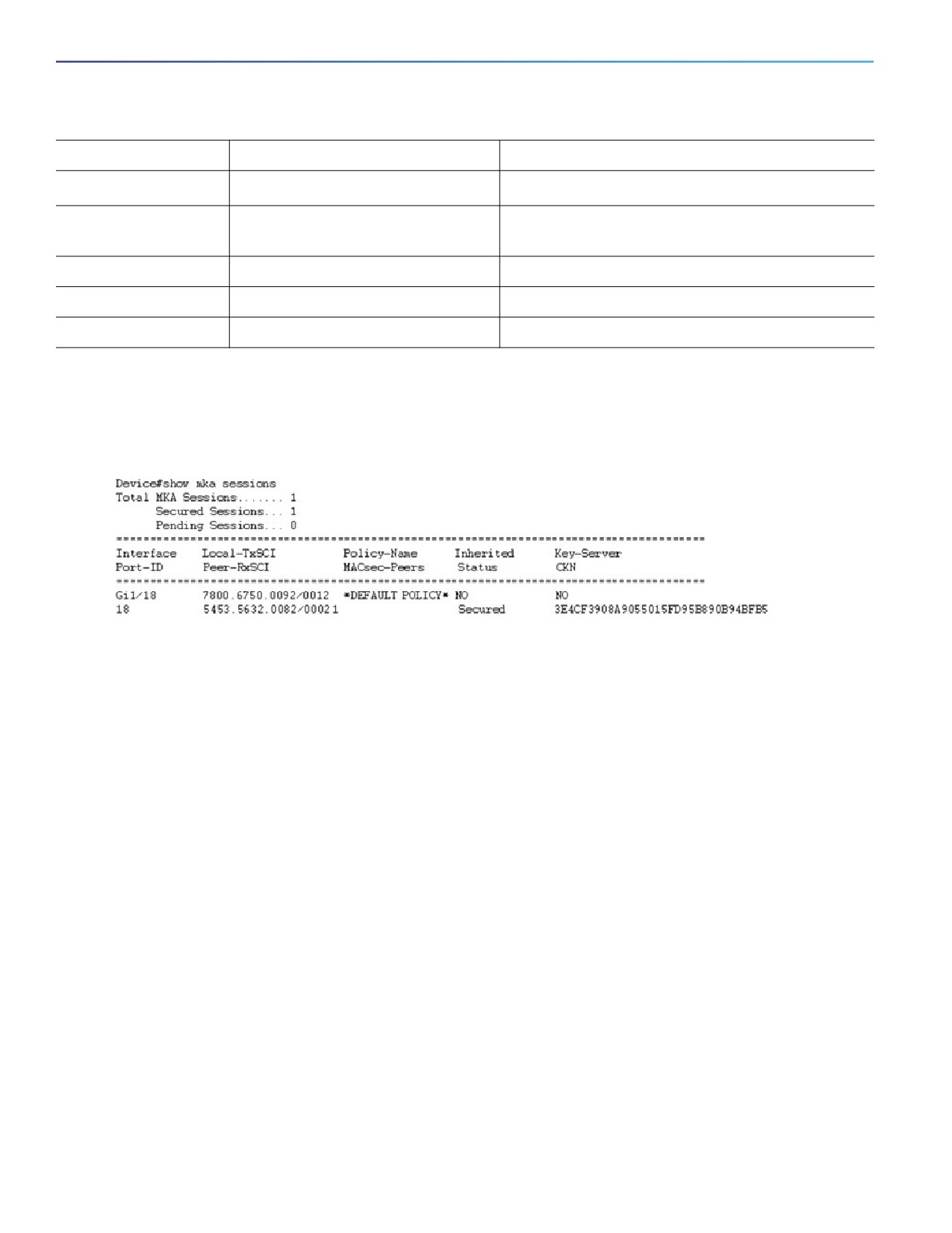
Use the following show commands to verify the configuration of certificate-based MACsec encryption. Sample output
is shown below.
The show access-session interface interface-id details displays detailed information about the access session for the
given interface.
Device#show access-session interface gi 1/18 details
Interface: GigabitEthernet1/18
MAC Address:
5453.5632.0082
IPv6 Address: Unknown
IPv4 Address: Unknown
User-Name: scepen.mkadt.cisco.com
Status: Authorized
Domain: DATA
Oper host mode: multi-host
Oper control dir: both
Session timeout: N/A
Restart timeout: N/A
Periodic Acct timeout: N/A
Session Uptime:
25s
Common Session ID:
000000000000000C0011E814
Acct Session ID:
0x00000001
Handle:
0xC0000001
Current Policy: MUSTS_1
Local Policies:
Service Template: DEFAULT_LINKSEC_POLICY_MUST_SECURE (priority 150)
Security Policy: Must Secure
Security Status: Link Secured
Server Policies:
Method status list:
Method
State
dot1xSupp
Authc Success
dot1x
Authc Success
252
MACsec
Certificate-based MACsec Encryption
Configuration examples for Certificate-based MACsec Encryption
Example: Enrolling the Certificate
Configure Crypto PKI Trustpoint:
crypto pki trustpoint demo
enrollment terminal
serial-number
fqdn MUSTS.mkadt.cisco.com
subject-name cn=MUSTS.mkadt.cisco.com,OU=CSG Security,O=Cisco Systems,L=Bengaluru,ST=KA,C=IN
subject-alt-name MUSTS.mkadt.cisco.com
revocation-check none
rsakeypair demo 2048
!
Manual Installation of Root CA certificate:
crypto pki authenticate demo
Example: Enabling 802.1x Authentication and AAA Configuration
aaa new-model
dot1x system-auth-control
radius server ISE
address ipv4 <ISE ipv4 address> auth-port 1645 acct-port 1646
key <secret configured on ise>
!
aaa group server radius ISEGRP
server name ISE
!
aaa authentication dot1x default group ISEGRP
aaa authorization network default group ISEGRP
!
Example: Configuring EAP-TLS Profile and 802.1X Credentials
eap profile scepen
method tls
pki-trustpoint demo
!
dot1x system-auth-control
dot1x credentials mis
username scepen.mkadt.cisco.com
!
Example: Applying 802.1X, PKI, and MACsec Configuration on the Interface
interface GigabitEthernet1/2
switchport mode access
macsec network-link
authentication periodic
access-session host-mode multi-host
access-session closed
access-session port-control auto
dot1x pae both
dot1x authenticator eap profile scepen
dot1x credentials mis
dot1x supplicant eap profile scepen
service-policy type control subscriber MUSTS_1
253
MACsec
Certificate-based MACsec Encryption
!
254
Configuring Web-Based Authentication
Prerequisites for Configuring Web-Based Authentication
By default, the IP device tracking feature is disabled on a switch. You must enable the IP device tracking feature to
use web-based authentication.
You must configure at least one IP address to run the switch HTTP server. You must also configure routes to reach
each host IP address. The HTTP server sends the HTTP login page to the host.
You must configure the default ACL on the interface before configuring web-based authentication. Configure a port
ACL for a Layer 2 interface.
Restrictions for Configuring Web-Based Authentication
Web-based authentication is an ingress-only feature.
You can configure web-based authentication only on access ports. Web-based authentication is not supported on
trunk ports, EtherChannel member ports, or dynamic trunk ports.
You cannot authenticate hosts on Layer 2 interfaces with static ARP cache assignment. These hosts are not detected
by the web-based authentication feature because they do not send ARP messages.
Hosts that are more than one hop away might experience traffic disruption if an STP topology change results in the
host traffic arriving on a different port. This occurs because the ARP and DHCP updates might not be sent after a
Layer 2 (STP) topology change.
Web-based authentication does not support VLAN assignment as a downloadable-host policy.
Web-based authentication is not supported for IPv6 traffic.
Web-based authentication and Network Edge Access Topology (NEAT) are mutually exclusive. You cannot use
web-based authentication when NEAT is enabled on an interface, and you cannot use NEAT when web-based
authentication is running on an interface.
Web-based authentication supports only RADIUS authorization servers. You cannot use TACACS+ servers or local
authorization.
Information About Configuring Web-Based Authentication
Web-Based Authentication
Use the web-based authentication feature, known as web authentication proxy, to authenticate end users on host
systems that do not run the IEEE 802.1x supplicant.
Note: You can configure web-based authentication on Layer 2 interfaces.
255
Configuring Web-Based Authentication
Information About Configuring Web-Based Authentication
When you initiate an HTTP session, web-based authentication intercepts ingress HTTP packets from the host and sends
an HTML login page to the users. The users enter their credentials, which the web-based authentication feature sends
to the authentication, authorization, and accounting (AAA) server for authentication.
If authentication succeeds, web-based authentication sends a Login-Successful HTML page to the host and applies the
access policies returned by the AAA server.
If authentication fails, web-based authentication forwards a Login-Fail HTML page to the user, prompting the user to
retry the login. If the user exceeds the maximum number of attempts, web-based authentication forwards a
Login-Expired HTML page to the host, and the user is placed on a watch list for a waiting period.
These sections describe the role of web-based authentication as part of AAA:
Device Roles, page 256
Host Detection, page 256
Session Creation, page 257
Authentication Process, page 257
Web Authentication Customizable Web Pages, page 260
Web-Based Authentication Interactions with Other Features, page 261
Device Roles
With web-based authentication, the devices in the network have these specific roles:
Client—The device (workstation) that requests access to the LAN and the services and responds to requests from
the switch. The workstation must be running an HTML browser with Java Script enabled.
Authentication server—Authenticates the client. The authentication server validates the identity of the client and
notifies the switch that the client is authorized to access the LAN and the switch services or that the client is denied.
Switch—Controls the physical access to the network based on the authentication status of the client. The switch acts
as an intermediary (proxy) between the client and the authentication server, requesting identity information from the
client, verifying that information with the authentication server, and relaying a response to the client.
Figure 24
Web-Based Authentication Device Roles
Host Detection
The switch maintains an IP device tracking table to store information about detected hosts.
Note: By default, the IP device tracking feature is disabled on a switch. You must enable the IP device tracking feature
to use web-based authentication.
256
Configuring Web-Based Authentication
Information About Configuring Web-Based Authentication
For Layer 2 interfaces, web-based authentication detects IP hosts by using these mechanisms:
ARP-based trigger—ARP redirect ACL allows web-based authentication to detect hosts with a static IP address or
a dynamic IP address.
Dynamic ARP inspection
DHCP snooping—Web-based authentication is notified when the switch creates a DHCP-binding entry for the host.
Session Creation
When web-based authentication detects a new host, it creates a session as follows:
Reviews the exception list.
If the host IP is included in the exception list, the policy from the exception list entry is applied, and the session is
established.
Reviews for authorization bypass.
If the host IP is not on the exception list, web-based authentication sends a nonresponsive-host (NRH) request to
the server.
If the server response is access accepted, authorization is bypassed for this host. The session is established.
Sets up the HTTP intercept ACL.
If the server response to the NRH request is access rejected, the HTTP intercept ACL is activated, and the session
waits for HTTP traffic from the host.
Authentication Process
When you enable web-based authentication, these events occur:
The user initiates an HTTP session.
The HTTP traffic is intercepted, and authorization is initiated. The switch sends the login page to the user. The user
enters a username and password, and the switch sends the entries to the authentication server.
If the authentication succeeds, the switch downloads and activates the user’s access policy from the authentication
server. The login success page is sent to the user.
If the authentication fails, the switch sends the login fail page. The user retries the login. If the maximum number of
attempts fails, the switch sends the login expired page, and the host is placed in a watch list. After the watch list
times out, the user can retry the authentication process.
If the authentication server does not respond to the switch, and if an AAA fail policy is configured, the switch applies
the failure access policy to the host. The login success page is sent to the user. (See Local Web Authentication
Banner, page 258.)
The switch reauthenticates a client when the host does not respond to an ARP probe on a Layer 2 interface, or when
the host does not send any traffic within the idle timeout on a Layer 3 interface.
The feature applies the downloaded timeout or the locally configured session timeout.
If the terminate action is RADIUS, the feature sends a nonresponsive host (NRH) request to the server. The terminate
action is included in the response from the server.
If the terminate action is default, the session is dismantled, and the applied policy is removed.
257
Configuring Web-Based Authentication
Information About Configuring Web-Based Authentication
Local Web Authentication Banner
You can create a banner that will appear when you log in to a switch by using web authentication.
The banner appears on both the login page and the authentication-result pop-up pages:
Authentication Successful
Authentication Failed
Authentication Expired
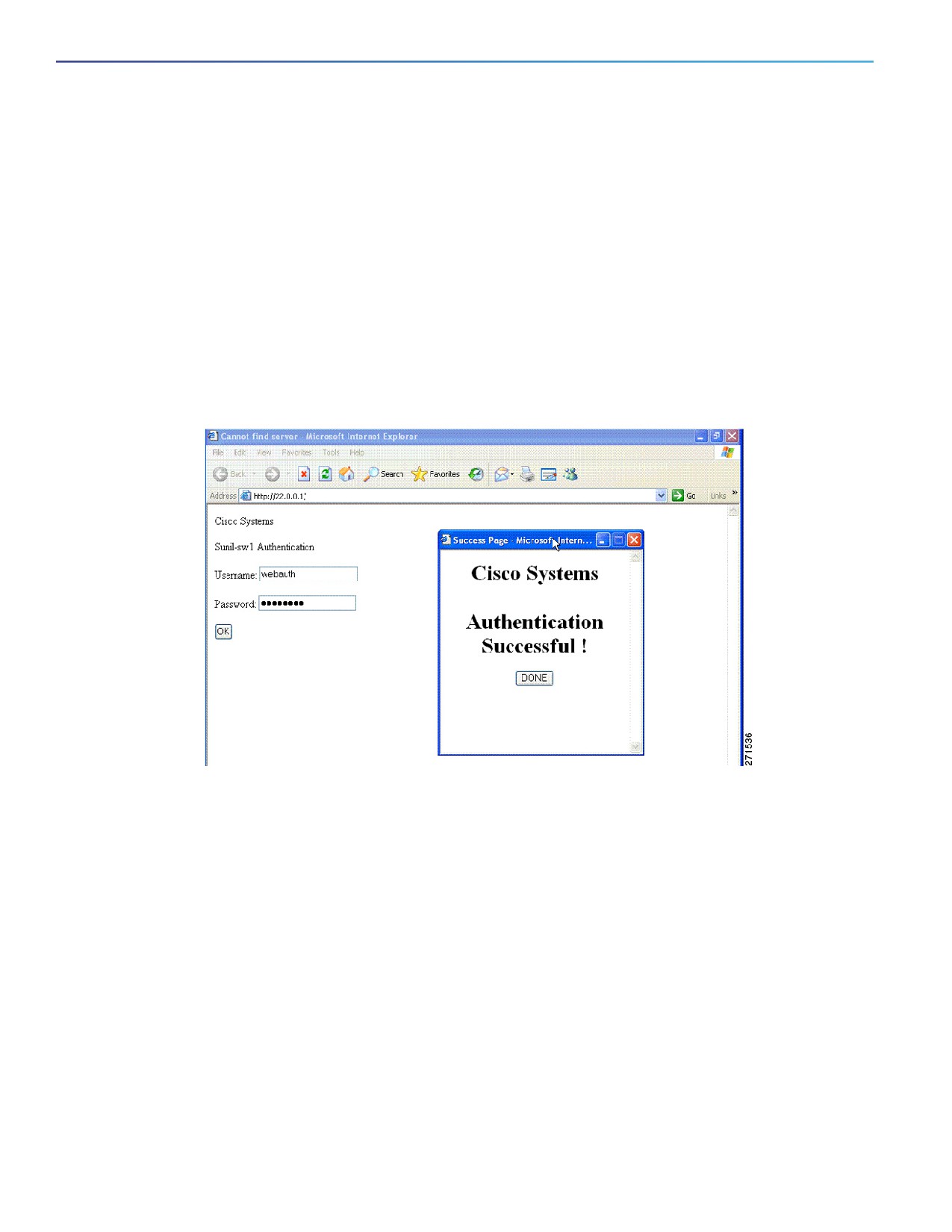
You create a banner by using the ip admission auth-proxy-banner http global configuration command. The default
banner Cisco Systems and Switch host-name Authentication appear on the Login Page. Cisco Systems appears on the
authentication result pop-up page, as shown in Figure 25 on page 258.
Figure 25
Authentication Successful Banner
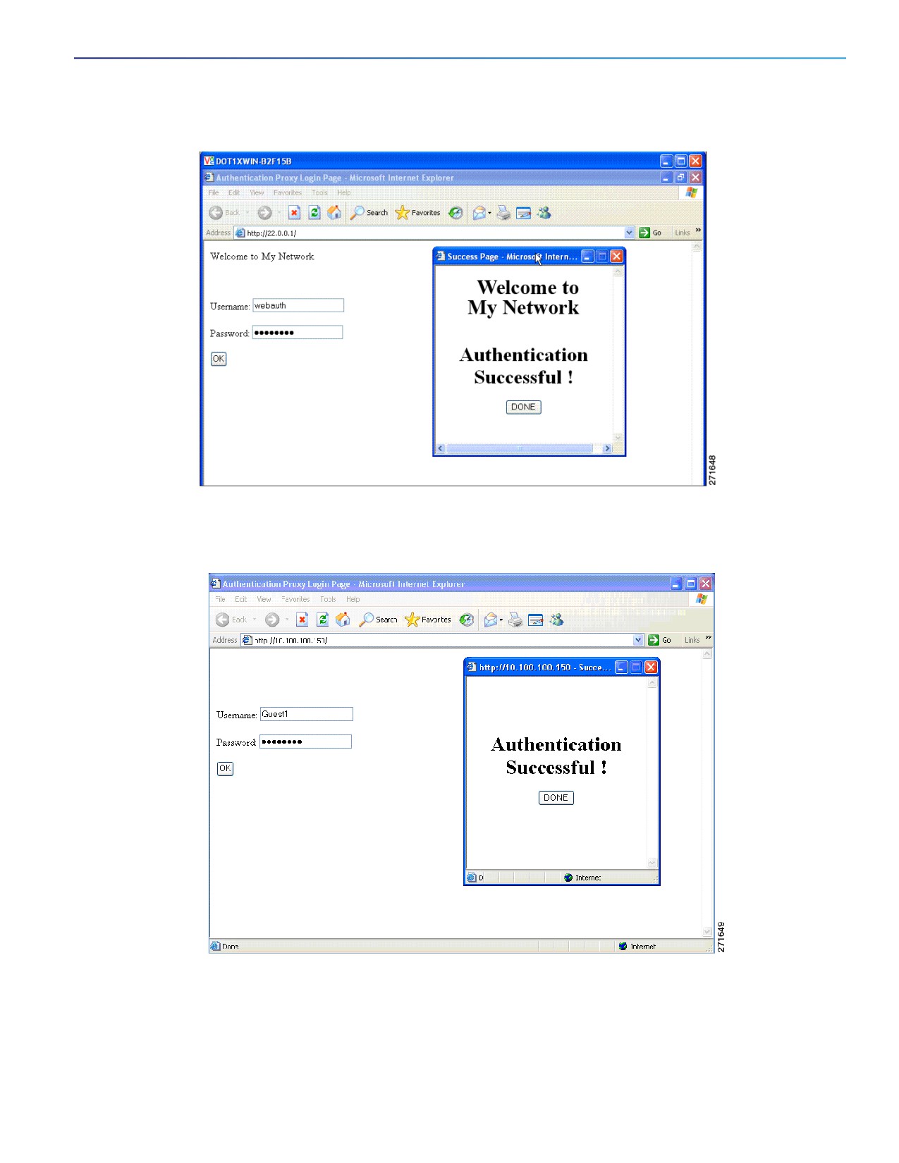
You can also customize the banner, as shown in Figure 26 on page 259.
Add a switch, router, or company name to the banner by using the ip admission auth-proxy-banner http
banner-text global configuration command.
Add a logo or text file to the banner by using the ip admission auth-proxy-banner http file-path global
configuration command.
258
Configuring Web-Based Authentication
Information About Configuring Web-Based Authentication
Figure 26
Customized Web Banner
If you do not enable a banner, only the username and password dialog boxes appear in the web authentication login
screen, and no banner appears when you log into the switch, as shown in Figure 27.
Figure 27
Login Screen with No Banner
For more information, see the Cisco IOS Security Command Reference and Configuring a Web Authentication Local
Banner, page 266.
259
Configuring Web-Based Authentication
Information About Configuring Web-Based Authentication
Web Authentication Customizable Web Pages
During the web-based authentication process, the switch internal HTTP server hosts four HTML pages to deliver to an
authenticating client. The server uses these pages to notify you of these four-authentication process states:
Login—Your credentials are requested.
Success—The login was successful.
Fail—The login failed.
Expire—The login session has expired because of excessive login failures.
Web Authentication Guidelines
You can substitute your own HTML pages for the default internal HTML pages.
You can use a logo or specify text in the login, success, failure, and expire web pages.
On the banner page, you can specify text in the login page.
The pages are in HTML.
You must include an HTML redirect command in the success page to access a specific URL.
The URL string must be a valid URL (for example, http://www.cisco.com). An incomplete URL might cause page not
found error or similar errors on a web browser.
If you configure web pages for HTTP authentication, they must include the appropriate HTML commands (for
example, to set the page time out, to set a hidden password, or to confirm that the same page is not submitted
twice).
The CLI command to redirect users to a specific URL is not available when the configured login form is enabled. The
administrator should ensure that the redirection is configured in the web page.
If the CLI command redirecting users to a specific URL after authentication occurs is entered and then the command
configuring web pages is entered, the CLI command redirecting users to a specific URL does not take effect.
Configured web pages can be copied to the switch boot flash or flash.
Configured pages can be accessed from the flash on the stack master or members.
The login page can be on one flash, and the success and failure pages can be another flash (for example, the flash
on the stack master or a member).
You must configure all four pages.
The banner page has no effect if it is configured with the web page.
All of the logo files (image, flash, audio, video, and so on) that are stored in the system directory (for example, flash,
disk0, or disk) and that must be displayed on the login page must use web_auth_filename as the filename.
The configured authentication proxy feature supports both HTTP and SSL.
When configuring customized authentication proxy web pages, follow these guidelines:
To enable the custom web pages feature, specify all four custom HTML files. If you specify fewer than four files, the
internal default HTML pages are used.
The four custom HTML files must be present on the flash memory of the switch. The maximum size of each HTML
file is 8 KB.
260
Configuring Web-Based Authentication
Information About Configuring Web-Based Authentication
Any images on the custom pages must be on an accessible HTTP server. Configure an intercept ACL within the
admission rule.
Any external link from a custom page requires configuration of an intercept ACL within the admission rule.
To access a valid DNS server, any name resolution required for external links or images requires configuration of an
intercept ACL within the admission rule.
If the custom web pages feature is enabled, a configured auth-proxy-banner is not used.
If the custom web pages feature is enabled, the redirection URL for successful login feature is not available.
To remove the specification of a custom file, use the no form of the command.
Because the custom login page is a public web form, consider these guidelines for the page:
The login form must accept user entries for the username and password and must show them as uname and pwd.
The custom login page should follow best practices for a web form, such as page timeout, hidden password, and
prevention of redundant submissions.
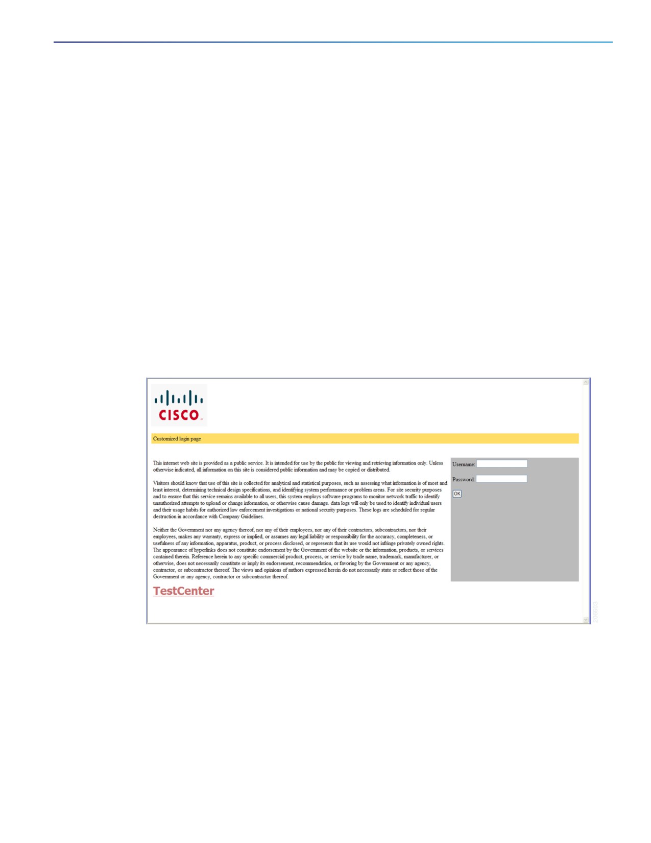
You can substitute your HTML pages, as shown in Figure 28, for the default internal HTML pages. You can also specify a
URL to which users are redirected after authentication occurs, which replaces the internal Success page.
Figure 28
Customizeable Authentication Page
Web-Based Authentication Interactions with Other Features
Port Security, page 262
LAN Port IP, page 262
Gateway IP, page 262
ACLs, page 262
261
Configuring Web-Based Authentication
Information About Configuring Web-Based Authentication
Context-Based Access Control, page 262
802.1x Authentication, page 262
EtherChannel, page 263
Port Security
You can configure web-based authentication and port security on the same port. Web-based authentication
authenticates the port, and port security manages network access for all MAC addresses, including that of the client. You
can then limit the number or group of clients that can access the network through the port.
LAN Port IP
You can configure LAN port IP (LPIP) and Layer 2 web-based authentication on the same port. The host is authenticated
by using web-based authentication first, followed by LPIP posture validation. The LPIP host policy overrides the
web-based authentication host policy.
If the web-based authentication idle timer expires, the NAC policy is removed. The host is authenticated, and posture is
validated again.
Gateway IP
You cannot configure Gateway IP (GWIP) on a Layer 3 VLAN interface if web-based authentication is configured on any
of the switch ports in the VLAN.
You can configure web-based authentication on the same Layer 3 interface as Gateway IP. The host policies for both
features are applied in software. The GWIP policy overrides the web-based authentication host policy.
ACLs
If you configure a VLAN ACL or a Cisco IOS ACL on an interface, the ACL is applied to the host traffic only after the
web-based authentication host policy is applied.
For Layer 2 web-based authentication, you must configure a port ACL (PACL) as the default access policy for ingress
traffic from hosts connected to the port. After authentication, the web-based authentication host policy overrides the
PACL.
Note: When a proxy ACL is configured for a web-based authentication client, the proxy ACL is downloaded and applied
as part of the authorization process. Hence, the PACL displays the proxy ACL access control entry (ACE).
You cannot configure a MAC ACL and web-based authentication on the same interface.
You cannot configure web-based authentication on a port whose access VLAN is configured for VACL capture.
Context-Based Access Control
Web-based authentication cannot be configured on a Layer 2 port if context-based access control (CBAC) is configured
on the Layer 3 VLAN interface of the port VLAN.
802.1x Authentication
You cannot configure web-based authentication on the same port as 802.1x authentication except as a fallback
authentication method.
262

Configuring Web-Based Authentication
How to Configure Web-Based Authentication
EtherChannel
You can configure web-based authentication on a Layer 2 EtherChannel interface. The web-based authentication
configuration applies to all member channels.
Default Web-Based Authentication Settings
Feature
Default Settings
AAA
Disabled
RADIUS server
IP address
None specified
UDP authentication port
1812
Key
None specified
Default value of inactivity timeout
3600 seconds
Inactivity timeout
Enabled
Configuring Switch-to-RADIUS-Server Communication
RADIUS security servers identification:
Host name
Host IP address
Host name and specific UDP port numbers
IP address and specific UDP port numbers
The combination of the IP address and UDP port number creates a unique identifier, that enables RADIUS requests to be
sent to multiple UDP ports on a server at the same IP address. If two different host entries on the same RADIUS server
are configured for the same service (for example, authentication) the second host entry that is configured functions as
the failover backup to the first one. The RADIUS host entries are chosen in the order that they were configured.
How to Configure Web-Based Authentication
Configuring the Authentication Rule and Interfaces
Command
Purpose
1.
ip admission name name proxy http
Configures an authentication rule for web-based authorization.
2.
interface type slot/port
Enters interface configuration mode and specifies the ingress Layer 2
interface to be enabled for web-based authentication.
type can be Gigabit Ethernet, or 10-Gigabit Ethernet.
3.
ip access-group name
Applies the default ACL.
4.
ip admission name
Configures web-based authentication on the specified interface.
263

Configuring Web-Based Authentication
How to Configure Web-Based Authentication
Command
Purpose
5.
exit
Returns to configuration mode.
6.
ip device tracking
Enables the IP device tracking table.
7.
end
Returns to privileged EXEC mode.
8.
show ip admission configuration
Displays the configuration.
Configuring AAA Authentication
Command
Purpose
1.
aaa new-model
Enables AAA functionality.
2.
aaa authentication login default group {tacacs+
Defines the list of authentication methods at login.
| radius}
3.
aaa authorization auth-proxy default group
Creates an authorization method list for web-based
{tacacs+ | radius}
authorization.
4.
radius-server host {hostname | ip-address} test
Specifies an AAA server.
username username
Specifies the host name or IP address of the remote RADIUS
server.
The test username username option enables automated
testing of the RADIUS server connection. The specified
username does not need to be a valid user name.
5.
radius-server key string
Configures the authorization and encryption key used between
the switch and the RADIUS daemon running on the RADIUS
server. To use multiple RADIUS servers, reenter this command
for each server.
Configuring Switch-to-RADIUS-Server Communication
Command
Purpose
1.
ip radius source-interface interface_name
Specifies that the RADIUS packets have the IP address of
the indicated interface.
2.
radius-server host {hostname | ip-address} test
Specifies the host name or IP address of the remote
username username
RADIUS server.
The test username username option enables automated
testing of the RADIUS server connection. The specified
username does not need to be a valid user name.
The key option specifies an authentication and
encryption key to use between the switch and the
RADIUS server.
To use multiple RADIUS servers, reenter this command
for each server.
264

Configuring Web-Based Authentication
How to Configure Web-Based Authentication
Command
Purpose
3.
radius-server key string
Configures the authorization and encryption key used
between the switch and the RADIUS daemon running on
the RADIUS server.
4.
radius-server vsa send authentication
Enables downloading of an ACL from the RADIUS server.
This feature is supported in
Cisco IOS Release 12.2(50)SG.
5.
radius-server dead-criteria tries num-tries
Specifies the number of unanswered sent messages to a
RADIUS server before considering the server to be
inactive. The range of num-tries is 1 to 100.
Configuring the HTTP Server
Command
Purpose
1.
ip http server
Enables the HTTP server. The web-based authentication feature uses the HTTP
server to communicate with the hosts for user authentication.
2.
ip http secure-server
Enables HTTPS.
Customizing the Authentication Proxy Web Pages
Before You Begin
You can configure web authentication to display four substitute HTML pages to the user in place of the switch default
HTML pages during web-based authentication.
To specify the use of your custom authentication proxy web pages, first store your custom HTML files on the switch flash
memory, then perform this task in global configuration mode:
Command
Purpose
1.
ip admission proxy http login page file
Specifies the location in the switch memory file system
device:login-filename
of the custom HTML file to use in place of the default
login page. The device: is flash memory.
2.
ip admission proxy http success page file
Specifies the location of the custom HTML file to use in
device:success-filename
place of the default login success page.
3.
ip admission proxy http failure page file
Specifies the location of the custom HTML file to use in
device:fail-filename
place of the default login failure page.
4.
ip admission proxy http login expired page file
Specifies the location of the custom HTML file to use in
device:expired-filename
place of the default login expired page.
Specifying a Redirection URL for Successful Login
You can specify a URL to which the user is redirected after authentication, effectively replacing the internal Success
HTML page.
Command
Purpose
ip admission proxy http success redirect url-string
Specifies a URL for redirection of the user in place of the
default login success page.
265

Configuring Web-Based Authentication
How to Configure Web-Based Authentication
Configuring the Web-Based Authentication Parameters
You can configure the maximum number of failed login attempts before the client is placed in a watch list for a waiting
period.
Command
Purpose
1.
ip admission max-login-attempts number
Sets the maximum number of failed login attempts. The
range is 1 to 2147483647 attempts. The default is 5.
2.
end
Returns to privileged EXEC mode.
3.
show ip admission configuration
Displays the authentication proxy configuration.
4.
show ip admission cache
Displays the list of authentication entries.
5.
copy running-config startup-config
(Optional) Saves your entries in the configuration file.
Configuring a Web Authentication Local Banner
Command
Purpose
1.
configure terminal
Enters global configuration mode.
2.
ip admission auth-proxy-banner http
Enables the local banner.
[banner-text | file-path]
(Optional) Creates a custom banner by entering C banner-text C,
where C is a delimiting character or a file-path indicates a file (for
example, a logo or text file) that appears in the banner.
3.
end
Returns to privileged EXEC mode.
4.
copy running-config startup-config
(Optional) Saves your entries in the configuration file.
Removing Web-Based Authentication Cache Entries
Enter a specific IP address to delete the entry for a single host. Use an asterisk to delete all cache entries.
266

Configuring Web-Based Authentication
Monitoring and Maintaining Web-Based Authentication
Command
Purpose
clear ip auth-proxy cache {* | host ip address}
Clears authentication proxy entries from the switch.
clear ip admission cache {* | host ip address}
Clears IP admission cache entries from the switch.
Monitoring and Maintaining Web-Based Authentication
Command
Purpose
show authentication sessions
Displays the web-based authentication settings.
show ip admission configuration
Displays the authentication proxy configuration.
show ip admission cache
Displays the list of authentication entries.
Configuration Examples for Configuring Web-Based
Authentication
Enabling and Displaying Web-Based Authentication: Examples
This example shows how to verify the configuration:
Switch# show ip admission configuration
Authentication Proxy Banner not configured
Authentication global cache time is 60 minutes
Authentication global absolute time is 0 minutes
Authentication global init state time is 2 minutes
Authentication Proxy Watch-list is disabled
Authentication Proxy Rule Configuration
Auth-proxy name webauth1
http list not specified inactivity-time 60 minutes
Authentication Proxy Auditing is disabled
Max Login attempts per user is 5
Enabling AAA: Example
This example shows how to enable AAA:
Switch(config)# aaa new-model
Switch(config)# aaa authentication login default group radius
Switch(config)# aaa authorization auth-proxy default group radius
Configuring the RADIUS Server Parameters: Example
This example shows how to configure the RADIUS server parameters on a switch:
Switch(config)# ip radius source-interface Vlan80
Switch(config)# radius-server host 172.l20.39.46 test username user1
Switch(config)# radius-server key rad123
Switch(config)# radius-server dead-criteria tries 2
267
Configuring Web-Based Authentication
Configuration Examples for Configuring Web-Based Authentication
Configuring a Custom Authentication Proxy Web Page: Example
This example shows how to configure custom authentication proxy web pages:
Switch(config)# ip admission proxy http login page file flash:login.htm
Switch(config)# ip admission proxy http success page file flash:success.htm
Switch(config)# ip admission proxy http fail page file flash:fail.htm
Switch(config)# ip admission proxy http login expired page flash flash:expired.htm
Verifying a Custom Authentication Proxy Web Page: Example
This example shows how to verify the configuration of a custom authentication proxy web pages:
Switch# show ip admission configuration
Authentication proxy webpage
Login page
: flash:login.htm
Success page
: flash:success.htm
Fail Page
: flash:fail.htm
Login expired Page
: flash:expired.htm
Authentication global cache time is 60 minutes
Authentication global absolute time is 0 minutes
Authentication global init state time is 2 minutes
Authentication Proxy Session ratelimit is 100
Authentication Proxy Watch-list is disabled
Authentication Proxy Auditing is disabled
Max Login attempts per user is 5
Configuring a Redirection URL: Example
This example shows how to configure a redirection URL for successful login:
Switch(config)# ip admission proxy http success redirect www.cisco.com
Verifying a Redirection URL: Example
This example shows how to verify the redirection URL for successful login:
Switch# show ip admission configuration
Authentication Proxy Banner not configured
Customizable Authentication Proxy webpage not configured
HTTP Authentication success redirect to URL: http://www.cisco.com
Authentication global cache time is 60 minutes
Authentication global absolute time is 0 minutes
Authentication global init state time is 2 minutes
Authentication Proxy Watch-list is disabled
Authentication Proxy Max HTTP process is 7
Authentication Proxy Auditing is disabled
Max Login attempts per user is 5
Configuring a Local Banner: Example
This example shows how to configure a local banner with the custom message My Switch:
Switch(config) configure terminal
Switch(config)# aaa new-model
Switch(config)# aaa ip auth-proxy auth-proxy-banner C My Switch C
Switch(config) end
268
Configuring Web-Based Authentication
Additional References
Clearing the Web-Based Authentication Session: Example
This example shows how to remove the web-based authentication session for the client at the IP
address 209.165.201.1:
Switch# clear ip auth-proxy cache 209.165.201.1
Additional References
The following sections provide references related to switch administration:
269

Configuring Web-Based Authentication
Additional References
Related Documents
Related Topic
Document Title
Cisco IOS basic commands
Cisco IOS Configuration Fundamentals Command Reference
Authentication proxy commands
Cisco IOS Security Command Reference
Radius server commands
Authentication proxy configuration
Cisco IOS Security Configuration Guide
Radius server configuration
Standards
Standards
Title
No new or modified standards are supported by this
—
feature, and support for existing standards has not
been modified by this feature.
MIBs
MIBs
MIBs Link
—
To locate and download MIBs using Cisco IOS XR software, use the
Cisco MIB Locator found at the following URL and choose a platform
under the Cisco Access Products menu:
RFCs
RFCs
Title
No new or modified RFCs are supported by this
—
feature, and support for existing RFCs has not been
modified by this feature.
Technical Assistance
Description
Link
The Cisco Technical Support website contains
thousands of pages of searchable technical content,
including links to products, technologies, solutions,
technical tips, and tools. Registered Cisco.com users
can log in from this page to access even more content.
270

Configuring Smartports Macros
Information About Configuring Smartports Macros
Smartports macros provide a convenient way to save and share common configurations. You can use Smartports macros
to enable features and settings based on the location of a switch in the network and for mass configuration deployments
across the network.
Each Smartports macro is a set of CLI commands that you define. Smartports macros do not contain new CLI commands;
they are simply a group of existing CLI commands.
When you apply a Smartports macro to an interface, the CLI commands within the macro are configured on the interface.
When the macro is applied to an interface, the existing interface configurations are not lost. The new commands are
added to the interface and are saved in the running configuration file.
How to Configure Smartports Macros
Default Smartports Settings
There are no Smartports macros enabled on the switch.
Table 31
Default Smartports Macros
Macro Name1
Description
Global Configuration Macros
cisco-cg-global
Use this global configuration macro to configure the switch settings for the industrial Ethernet
environment. This macro is automatically applied when you use Express Setup to initially
configure the switch.
Note: You must first apply the cisco-cg-global macro for the interface configuration macros to
work properly.
cisco-cg-password
Use this global configuration macro to configure the password settings for the switch.
no-cisco-cg-password
Use the no form of this global configuration macro to delete the macro from the switch.
cisco-sniffer
Use this global configuration macro to configure SPAN functionality to analyze traffic on another
port of the switch.
no-cisco-sniffer
Use the no form of this global configuration macro to delete the macro from the interface.
Interface Configuration Macros
cisco-ethernetip
Use this interface configuration macro when connecting the switch to an EtherNet IP device.
Note: You must first apply the cisco-ie-global macro for the cisco-ethernetip macro to work
properly.
no-cisco-ethernetip
Use the no form of this global configuration macro to delete the macro from the interface.
271

Configuring Smartports Macros
How to Configure Smartports Macros
Table 31
Default Smartports Macros (continued)
Macro Name1
Description
Global Configuration Macros
cisco-cg-hmi
Use this interface configuration macro for increased network security and reliability when
connecting a desktop device, such as a PC, to a switch port. This macro is optimized for utility
deployments.
no-cisco-cg-hmi
Use the no form of this interface configuration macro to delete the macro from the switch.
cisco-cg-ied
Use this interface configuration macro when connecting the switch to an IED.
no-cisco-cg-ied
Use the no form of this interface configuration macro to delete the macro from the switch.
cisco-ie-phone
Use this interface configuration macro when connecting a desktop device such as a PC with a
Cisco IP Phone to a switch port. This macro is an extension of the cisco-desktop macro and
provides the same security and resiliency features, but with the addition of dedicated voice
VLANs to ensure proper treatment of delay-sensitive voice traffic.
no-cisco-ie-phone
Use the no form of this interface configuration macro to delete the macro from the switch.
cisco-cg-router
Use this interface configuration macro when connecting the switch and a WAN router. This macro
is optimized for utility deployments.
no-cisco-cg-router
Use the no form of this interface configuration macro to delete the macro from the switch.
cisco-cg-switch
Use this interface configuration macro when connecting a ring of switches. This macro is
optimized for utility deployments.
no-cisco-cg-switch
Use the no form of this interface configuration macro to delete the macro from the switch.
cisco-cg-wireless
Use this interface configuration macro when connecting the switch and a wireless access point.
This macro is optimized for utility deployments.
no-cisco-cg-wireless
Use the no form of this interface configuration macro to delete the macro from the switch.
cisco-desktop
Use this interface configuration macro for increased network security and reliability when
connecting a desktop device, such as a PC, to a switch port. This macro is optimized for utility
deployments.
no-cisco-desktop
Use the no form of this interface configuration macro to delete the macro from the interface.
cisco-ie-none
The None Smartport is used to clear all Smartport configurations from the port.
cisco-ethernetip
Use this interface configuration macro when connecting the switch to an EtherNet IP device.
Note: You must first apply the cisco-ie-global macro for the cisco-ethernetip macro to work
properly.
cisco-ie-global
Use this global configuration macro to configure the switch settings for the industrial Ethernet
environment. This macro is automatically applied when you use Express Setup to initially
configure the switch.
Note: You must first apply the cisco-ie-global macro for the cisco-ethernetip macro to work
properly.
cisco-ie-desktop
Use this interface configuration macro for increased network security and reliability when
connecting a desktop device, such as a PC, to a switch port. This macro is optimized for
industrial automation traffic.
cisco-ie-phone
Use this interface configuration macro when connecting a desktop device such as a PC with a
Cisco IP Phone to a switch port. This macro is an extension of the cisco-ie-desktop macro and
provides the same security and resiliency features, but with the addition of dedicated voice
VLANs to ensure proper treatment of delay-sensitive voice traffic. This macro is optimized for
industrial automation traffic.
272

Configuring Smartports Macros
How to Configure Smartports Macros
Table 31
Default Smartports Macros (continued)
Macro Name1
Description
Global Configuration Macros
cisco-ie-router
Use this interface configuration macro when connecting the switch and a WAN router. This macro
is optimized for industrial automation traffic.
cisco-ie-switch
Use this interface configuration macro when connecting an access switch and a distribution
switch or between access switches connected using small form-factor pluggable (SFP)
modules. This macro is optimized for industrial automation traffic.
cisco-ie-wireless
Use this interface configuration macro when connecting the switch and a wireless access point.
This macro is optimized for industrial automation traffic.
1. Cisco-default Smartports macros vary, depending on the software version running on your switch.
Smartports Configuration Guidelines
When a macro is applied globally to a switch or to a switch interface, all of the existing configurations on the interface
are retained. This is helpful when applying an incremental configuration.
If a command fails because of a syntax or a configuration error, the macro continues to apply the remaining
commands. You can use the macro global trace macro-name global configuration command or the macro trace
macro-name interface configuration command to apply and debug a macro to find any syntax or configuration
errors.
Some CLI commands are specific to certain interface types. If you apply a macro to an interface that does not accept
the configuration, the macro fails the syntax or the configuration check, and the switch returns an error message.
Applying a macro to an interface range is the same as applying a macro to a single interface. When you use an
interface range, the macro is applied sequentially to each interface within the range. If a macro command fails on
one interface, it is still applied to the remaining interfaces.
When you apply a macro to a switch or a switch interface, the macro name is automatically added to the switch or
interface. You can display the applied commands and macro names by using the show running-config user EXEC
command.
Applying Smartports Macros
Command
Purpose
1.
show parser macro
Displays the Cisco-default Smartports macros embedded in the switch
software.
2.
show parser macro name macro-name
Displays the specific macro that you want to apply.
3.
configure terminal
Enters global configuration mode.
273

Configuring Smartports Macros
Monitoring and Maintaining Smartports Macros
Command
Purpose
4.
macro global {apply | trace}
Applies each individual command defined in the macro to the switch by
macro-name [parameter {value}]
entering macro global apply macro-name. Specifies macro global
[parameter {value}] [parameter {value}]
trace macro-name to apply and to debug a macro to find any syntax or
configuration errors.
Appends the macro with the required values by using the parameter
value keywords. Keywords that begin with $ require a unique parameter
value.
You can use the macro global apply macro-name ? command to
display a list of any required values for the macro. If you apply a macro
without entering the keyword values, the commands are invalid and are
not applied.
(Optional) Specifies unique parameter values that are specific to the
switch. You can enter up to three keyword-value pairs. Parameter
keyword matching is case sensitive. The corresponding value replaces
all matching occurrences of the keyword.
5.
interface interface-id
(Optional) Enters interface configuration mode and specifies the
interface on which to apply the macro.
6.
default interface interface-id
(Optional) Clears all configuration from the specified interface.
7.
macro {apply | trace} macro-name
Applies each individual command defined in the macro to the port by
[parameter {value}] [parameter {value}]
entering macro global apply macro-name. Specifies macro global
[parameter {value}]
trace macro-name to apply and to debug a macro to find any syntax or
configuration errors.
Appends the macro with the required values by using the parameter
value keywords. Keywords that begin with $ require a unique parameter
value.
You can use the macro global apply macro-name ? command to
display a list of any required values for the macro. If you apply a macro
without entering the keyword values, the commands are invalid and are
not applied.
(Optional) Specifies unique parameter values that are specific to the
switch. You can enter up to three keyword-value pairs. Parameter
keyword matching is case sensitive. The corresponding value replaces
all matching occurrences of the keyword.
8.
end
Returns to privileged EXEC mode.
9.
show running-config interface
Verifies that the macro is applied to an interface.
interface-id
10.
copy running-config startup-config
(Optional) Saves your entries in the configuration file.
Monitoring and Maintaining Smartports Macros
Table 32
Commands for Displaying Smartports Macros
Command
Purpose
show parser macro
Displays all Smartports macros.
274

Configuring Smartports Macros
Configuration Examples for Smartports Macros
Table 32
Commands for Displaying Smartports Macros (continued)
Command
Purpose
show parser macro name macro-name
Displays a specific Smartports macro.
show parser macro brief
Displays the Smartports macro names.
show parser macro description [interface
Displays the Smartports macro description for all interfaces or for a
interface-id]
specified interface.
Configuration Examples for Smartports Macros
Applying the Smartports Macro: Examples
This example shows how to display the cisco-ie-desktop macro, how to apply the macro and to set the access VLAN
ID to 25 on an interface:
Switch# show parser macro name cisco-ie-desktop
--------------------------------------------------------------
Macro name : cisco-ie-desktop
Macro type : default interface
# macro keywords ACCESS_VLAN
#macro name cisco-ie-desktop
switchport mode access
switchport access vlan ACCESS_VLAN
switchport port-security
switchport port-security maximum 1
switchport port-security aging time 2
switchport port-security violation restrict
switchport port-security aging type inactivity
spanning-tree portfast
spanning-tree bpduguard enable
no macro description
macro description cisco-ie-desktop
--------------------------------------------------------------
Switch#
Switch# configure terminal
Switch(config)# interface GigabitEthernet1/20
Switch(config-if)# macro apply cisco-ie-desktop $AVID 25
Additional References
The following sections provide references related to switch administration:
275