Cisco Industrial Ethernet 4000, 4010 and 5000 Switch Software. Configuration Guide (2022) - page 12

Configuring Smartports Macros
Additional References
Related Documents
Related Topic
Document Title
Cisco IOS basic commands
Cisco IOS Configuration Fundamentals Command Reference
Standards
Standards
Title
No new or modified standards are supported by this
—
feature, and support for existing standards has not
been modified by this feature.
MIBs
MIBs
MIBs Link
—
To locate and download MIBs using Cisco IOS XR software, use the
Cisco MIB Locator found at the following URL and choose a platform
under the Cisco Access Products menu:
RFCs
RFCs
Title
No new or modified RFCs are supported by this
—
feature, and support for existing RFCs has not been
modified by this feature.
Technical Assistance
Description
Link
The Cisco Technical Support website contains
thousands of pages of searchable technical content,
including links to products, technologies, solutions,
technical tips, and tools. Registered Cisco.com users
can log in from this page to access even more content.
276
Configuring SGACL Monitor Mode and SGACL Logging
Restrictions for Configuring SGACL Policies
Configuring SGACL Monitor Mode and
SGACL Logging
SGACL Monitor Mode and SGACL Logging are supported on IE 4000, IE 4010, and IE 5000 Series Switches in Cisco IOS
Release 15.2(8)E and later.
Security group-based access control is a component of the Cisco TrustSec security architecture, which builds secure
networks by establishing domains of trusted network devices. For comprehensive information about TrustSec, including
TrustSec prerequisites, guidelines and limitations, and configuration procedures, see Cisco TrustSec Switch
Configuration Guide. For information about Configuring SGT Exchange Protocol over TCP (SXP) and Layer 3 Transport,
see Configuring SGT Exchange Protocol over TCP (SXP) and Layer 3 Transport, page 281.
Restrictions for Configuring SGACL Policies
The following restrictions apply to the Cisco IE 4000, IE 4010, and IE 5000 Series Switches when configuring SGACL
policies:
Cisco TrustSec can be configured only on physical interfaces, not on logical interfaces.
When SXP is configured between a Cisco IE 4000, IE 4010, or IE 5000 switch and another switch, SGACL policies
are not enforced on Cisco IE 4000, IE 4010, or IE 5000 series switches. SGACL policies are downloaded for the
destination SGT, but policy statements are not applied to the traffic that is initiated from the source SGT.
IP device tracking must be enabled on both switches and these switches should have Layer2 adjacency configured
between them so that a Cisco IE 4000, IE 4010, or IE 5000 can tag packets with the corresponding SGT learned via
the SXP protocol.
You can enable IP device tracking on Cisco IE 4000, IE 4010, or IE 5000 series switches by using the ip device
tracking maximum < number > command. Based on your topology, configure the number of IP clients using the
number argument. We do not recommend configuring a high number of IP clients on ports/interfaces.
IP device tracking is enabled by default on all ports in Cisco IOS Release 15.2(1)E, and in Cisco IE 4000, IE 4010,
and IE 5000 switches using this release image, SGACL policies are enforced.
CTS SGACLs cannot be enforced for punt (CPU bound) traffic due to hardware limitations.
The following restrictions apply to IPv6 SGACL enforcement:
SGACL enforcement is bypassed for IPv6 multicast traffic.
SGACL enforcement is bypassed for IPv6 packets with Link-Local IPv6 source/destination addresses.
SGACL Monitor Mode
During the pre-deployment phase of Cisco TrustSec, you can use monitor mode to test security policies without
enforcing them to make sure that the policies function as intended. If the security policies do not function as intended,
monitor mode identifies that and allows you to correct the policy before enabling security group access control list
(SGACL) enforcement. Seeing the outcome of the policy actions before enforcing them lets you confirm that the subject
policy meets the security requirements (access is denied to resources if users are not authorized).
The monitoring capability is provided at the SGT-DGT pair level. When you enable the SGACL monitoring mode feature,
the deny action is implemented as an ACL permit on the line cards. This allows the SGACL counters and logging to
display how connections are handled by the SGACL policy. Since all the monitored traffic is permitted, there is no
disruption of service due to SGACLs while in the SGACL monitor mode.
277

Configuring SGACL Monitor Mode and SGACL Logging
SGACL Monitor Mode
The IPServices license is required to enable SGACL Monitor Mode.
Configuring SGACL Monitor Mode - CLI
To configure SGACL Monitor Mode through the CLI, follow these steps:
Command
Purpose
Switch# configure terminal
1.
Enters global configuration mode.
2.
Switch(config)#cts role-based monitor
Enables monitor mode.
enable
Switch(config)# cts role-based monitor
3.
Enables monitor mode for IPv4 RBACL (SGT-DGT
permissions from { sgt_num } to {
pair).
dgt_num } ipv4
Switch(config)# exit
4.
Exits configuration mode.
Switch# show cts role-based permissions
5.
(Optional) Displays the SGACL policies and details
from { sgt_num } to { dgt_num } ipv4 [
about the monitor mode feature for each pair. The
details ]
command output displays “monitored” if per cell
monitor mode is enabled for the <SGT-DGT> pair.
Configuring SGACL Monitor Mode - Radius (ISE)
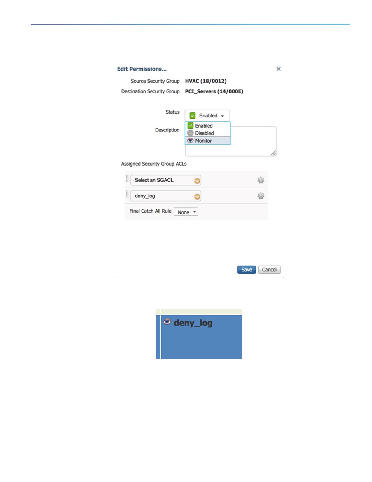
To enable SGACL Monitor Mode using the Cisco Identity Services Engine (ISE) GUI, select Monitor as shown below:
278
Configuring SGACL Monitor Mode and SGACL Logging
SGACL Monitor Mode
An eye icon indicates that Monitor mode is enabled.
The policy matrix change needs to be pushed to network devices by using the Deploy function at the top of the matrix.
This utilizes RADIUS CoA to inform the devices that a change has been made.
After the update is downloaded to the switch, use the show cts role-based permissions command to verify the
configuration. The policy permissions show the specific policy in Monitor Mode by appending the term “monitored”.
279
Configuring SGACL Monitor Mode and SGACL Logging
SGACL Logging
Verifying Configuration
The following examples are output from the show cts role-based permissions and show cts role-based counters
commands, which you can use to display SGACL Monitor Mode status.
Switch#show cts role-based permissions
IPv4 Role-based permissions default:
Permit IP-00
IPv4 Role-based permissions from group 18:HVAC to group 14:PCI_Servers (monitored):
deny_log-10
RBACL Monitor All for Dynamic Policies : FALSE
RBACL Monitor All for Configured Policies : FALSE
The HW-Monitor column of show cts role-based counters displays the count of enforcement events that are being
monitored in hardware and not actually enforced.
Switch#show cts role-based counters
Role-based IPv4 counters
From
To
SW-Denied HW-Denied SW-Permitt HW-Permitt SW-Monitor HW-Monitor
0
0
5378613
6291011
0
0
18
14
0
0
0
0
0
84
SGACL Logging
The log option in cts applies to individual ACEs and causes packets that match the ACE to be logged. The first packet
logged by the log keyword generates a syslog message.
SGACL Logging is only triggered when the Cisco ACE Application Control Engine has the logging keyword.
When logging is enabled in SGACL, the switch logs the following information:
The source security group tag (SGT) and destination SGT
The SGACL policy name
The packet protocol type
The action performed on the packet
To enable Cisco TrustSec role-based (security group) access control enforcement, use the
cts role-based enforcement command in global configuration mode. To configure a logging interval for an SGACL,
enter:
cts role-based enforcement [logging-interval interval ]
The valid values for the interval argument are from 5 to 86400 seconds. The default is 300 seconds.
To enable logging, use the log keyword before the ACE definition in the SGACL configuration. For example, permit ip log.
The following is a sample log, displaying source and destination SGTs, ACE matches for deny action). The
logging rate-limit command can be used to limit the rate of messages logged per second.
Switch(config)# cts role-based enforcement logging-interval 90
Switch(config)# logging rate-limit
May 27 10:19:21.509: %RBM-6-SGACLHIT:
ingress_interface='GigabitEthernet1/0/2' sgacl_name='sgacl2' action='Deny'
protocol='icmp' src-ip='16.16.1.3' src-port='8' dest-ip='17.17.1.2' dest-port='0'
sgt='101' dgt='202' logging_interval_hits='5'
280
Configuring SGT Exchange Protocol over
TCP (SXP) and Layer 3 Transport
You can use the SGT Exchange Protocol (SXP) to propagate the SGTs across network devices that do not have hardware
support for Cisco TrustSec. This section describes how to configure Cisco TrustSec SXP on switches in your network.
This section includes the following topics:
Cisco TrustSec SGT Exchange Protocol Feature Histories, page 281
Configuring Cisco TrustSec SXP, page 281
Configuring the Default SXP Password, page 284
Configuring the Default SXP Source IP Address, page 284
Changing the SXP Reconciliation Period, page 284
Changing the SXP Retry Period, page 285
Creating Syslogs to Capture Changes of IP Address to SGT Mapping Learned Through SXP, page 285
Verifying the SXP Connections, page 285
Configuring Cisco TrustSec Caching, page 286
Cisco TrustSec SGT Exchange Protocol Feature Histories
For a list of supported TrustSec features per platform and the minimum required Cisco IOS release, see
the Cisco TrustSec Platform Support Matrix at the following URL: (final URL posted with TS 4.0)
Otherwise, see product release notes for detailed feature introduction information.
Note: vrf aware sgt is currently not supported.
Configuring Cisco TrustSec SXP
To configure Cisco TrustSec SXP, follow these steps:
1. Enable the Cisco TrustSec feature (see the “Configuring Identities, Connections, and SGTs” chapter in the Cisco
TrustSec Switch Configuration Guide at:
ml#wpxref29406).
2. Enable Cisco TrustSec SXP (see Enabling Cisco TrustSec SXP, page 282).
281

Configuring SGT Exchange Protocol over TCP (SXP) and Layer 3 Transport
Configuring Cisco TrustSec SXP
3. Configure SXP peer connections (see Configuring an SXP Peer Connection, page 282).
Enabling Cisco TrustSec SXP
You must enable Cisco TrustSec SXP before you can configure peer connections. To enable Cisco TrustSec SXP, perform
this task:
Command
Purpose
Router# configure terminal
1.
Enters global configuration mode.
2.
Router(config)# [no] cts sxp enable
Enables SXP for Cisco TrustSec.
Router(config)# exit
3.
Exits configuration mode.
Configuring an SXP Peer Connection
You must configure the SXP peer connection on both of the devices. One device is the speaker and the other is the
listener. When using password protection, make sure to use the same password on both ends.
Note: If a default SXP source IP address is not configured and you do not configure an SXP source address in the
connection, the Cisco TrustSec software derives the SXP source IP address from existing local IP addresses. The SXP
source address might be different for each TCP connection initiated from the switch.
To configure the SXP peer connection, perform this task:
282

Configuring SGT Exchange Protocol over TCP (SXP) and Layer 3 Transport
Configuring Cisco TrustSec SXP
Command
Purpose
Router# configure terminal
1.
Enters global configuration mode.
2.
Router(config)# cts sxp connection
Configures the SXP address connection.
peer peer-ipv4-addr
[source src-ipv4-addr]
The optional source keyword specifies the IPv4
password {default | none] mode {local |
address of the source device. If no address is
peer} {speaker | listener}
specified, the connection will use the default source
[vrf vrf-name]
address, if configured, or the address of the port.
The password keyword specifies the password that
SXP will use for the connection using the following
options:
default—Use the default SXP password you
configured using the cts sxp default password
command.
none—Do not use a password.
The mode keyword specifies the role of the remote
peer device:
local—The specified mode refers to the local
device.
peer—The specified mode refers to the peer
device.
speaker—Default. Specifies that the device is the
speaker in the connection.
listener—Specifies that the device is the listener in
the connection.
The optional vrf keyword specifies the VRF to the
peer. The default is the default VRF.
Router(config)# exit
3.
Exits configuration mode.
Router# show cts sxp connections
4.
(Optional) Displays the SXP connection information.
This example shows how to enable SXP and configure the SXP peer connection on Switch A, a speaker, for connection
to Switch B, a listener:
Router# configure terminal
Router(config)# cts sxp enable
Router(config)# cts sxp default password Cisco123
Router(config)# cts sxp default source-ip 10.10.1.1
Router(config)# cts sxp connection peer 10.20.2.2 password default mode local speaker
This example shows how to configure the SXP peer connection on Switch B, a listener, for connection to Switch A, a
speaker:
Router# configure terminal
Router(config)# cts sxp enable
Router(config)# cts sxp default password Cisco123
Router(config)# cts sxp default source-ip 10.20.2.2
Router(config)# cts sxp connection peer 10.10.1.1 password default mode local listener
283

Configuring SGT Exchange Protocol over TCP (SXP) and Layer 3 Transport
Configuring the Default SXP Password
Configuring the Default SXP Password
By default, SXP uses no password when setting up connections. You can configure a default SXP password for the
switch. In Cisco IOS Release 12.2(50)SY and later releases, you can specify an encrypted password for the SXP default
password.
To configure a default SXP password, perform this task:
Command
Purpose
Router# configure terminal
1.
Enters configuration mode.
2.
Router(config)# cts sxp default
Configures the SXP default password. You can enter
password [0 | 6 | 7] password
either a clear text password (using the 0 or no option)
or an encrypted password (using the 6 or 7 option).
The maximum password length is 32 characters.
Router(config)# exit#
3.
Exits configuration mode.
This example shows how to configure a default SXP password:
Router# configure terminal
Router(config)# cts sxp default password Cisco123
Configuring the Default SXP Source IP Address
SXP uses the default source IP address for all new TCP connections where a source IP address is not specified. There
is no effect on existing TCP connections when you configure the default SXP source IP address.
To configure a default SXP source IP address, perform this task:
Command
Purpose
Router# configure terminal
1.
Enters configuration mode.
2.
Router(config)# cts sxp default
Configures the SXP default source IP address.
source-ip src-ip-addr
Router(config)# exit
3.
Exits configuration mode.
This example shows how to configure an SXP default source IP address:
Router# configure terminal
Router(config)# cts sxp default source-ip 10.20.2.2
Changing the SXP Reconciliation Period
After a peer terminates an SXP connection, an internal hold-down timer starts. If the peer reconnects before the internal
hold-down timer expires, the SXP reconciliation period timer starts. While the SXP reconciliation period timer is active,
the Cisco TrustSec software retains the SGT mapping entries learned from the previous connection and removes invalid
entries. The default value is 120 seconds (2 minutes). Setting the SXP reconciliation period to 0 seconds disables the
timer and causes all entries from the previous connection to be removed.
To change the SXP reconciliation period, perform this task:
284

Configuring SGT Exchange Protocol over TCP (SXP) and Layer 3 Transport
Changing the SXP Retry Period
Command
Purpose
Router# configure terminal
1.
Enters configuration mode.
2.
Router(config)# cts sxp reconciliation
Changes the SXP reconciliation timer. The default
period seconds
value is 120 seconds (2 minutes). The range is from 0
to 64000.
Router(config)# exit
3.
Exits configuration mode.
Changing the SXP Retry Period
The SXP retry period determines how often the Cisco TrustSec software retries an SXP connection. When an SXP
connection is not successfully set up, the Cisco TrustSec software makes a new attempt to set up the connection after
the SXP retry period timer expires. The default value is 120 seconds. Setting the SXP retry period to 0 seconds disables
the timer and retries are not attempted.
To change the SXP retry period, perform this task:
Command
Purpose
Router# configure terminal
1.
Enters configuration mode.
Router(config)# cts sxp retry period
2.
Changes the SXP retry timer. The default value is 120
seconds
seconds (2 minutes). The range is from 0 to 64000.
Router(config)# exit
3.
Exits configuration mode.
Creating Syslogs to Capture Changes of IP Address to SGT
Mapping Learned Through SXP
When the cts sxp log binding-changes global configuration command is executed, SXP syslogs (sev 5 syslog) are
generated whenever a change to IP address to SGT binding occurs (add, delete, change). These changes are learned
and propagated on the SXP connection.
The default is no cts sxp log binding-changes.
To enable logging of binding changes, perform the following task:
Command
Purpose
Router# configure terminal
1.
Enters configuration mode.
2.
Router(config)# cts sxp log binding-changes
Turns on logging for IP to SGT binding changes.
Verifying the SXP Connections
To view the SXP connections, perform this task:
285

Configuring SGT Exchange Protocol over TCP (SXP) and Layer 3 Transport
Configuring Cisco TrustSec Caching
Command
Purpose
Router# show cts sxp connections
1.
Displays SXP status and connections.
[brief]
This example shows how to view the SXP connections:
Router# show cts sxp connections
SXP
: Enabled
Default Password : Set
Default Source IP: 10.10.1.1
Connection retry open period: 10 secs
Reconcile period: 120 secs
Retry open timer is not running
----------------------------------------------
Peer IP
: 10.20.2.2
Source IP
: 10.10.1.1
Conn status
: On
Conn Version
: 2
Connection mode
: SXP Listener
Connection inst# : 1
TCP conn fd
: 1
TCP conn password: default SXP password
Duration since last state change: 0:00:21:25 (dd:hr:mm:sec)
Total num of SXP Connections = 1
Configuring Cisco TrustSec Caching
Feature Name
Releases
Feature Information
TrustSec Caching
12.2(50) SY
This feature was introduced on the Catalyst 6500 series
switches.
Enabling Cisco TrustSec Caching
For quick recovery from brief outages, you can enable caching of authentication, authorization, and policy information for
Cisco TrustSec connections. Caching allows Cisco TrustSec devices to use unexpired security information to restore
links after an outage without requiring a full reauthentication of the Cisco TrustSec domain. The Cisco TrustSec devices
will cache security information in DRAM. If non-volatile (NV) storage is also enabled, the DRAM cache information will
also be stored to the NV memory. The contents of NV memory populate DRAM during a reboot.
Note: During extended outages, the Cisco TrustSec cache information is likely to become outdated.
To enable Cisco TrustSec caching, perform this task:
286

Configuring SGT Exchange Protocol over TCP (SXP) and Layer 3 Transport
Configuring Cisco TrustSec Caching
Command
Purpose
Router# configure terminal
1.
Enters configuration mode.
2.
Router(config)# [no] cts cache enable
Enables caching of authentication, authorization and
environment-data information to DRAM. The default is
disabled.
The no form of this command deletes all cached
information from DRAM and non-volatile storage.
Router(config)# [no] cts cache
3.
When DRAM caching is enabled, enables DRAM
nv-storage {bootdisk: | bootflash: |
cache updates to be written to non-volatile storage.
disk0:} [directory dir-name]
Also enables DRAM cache to be initially populated
from non-volatile storage when the device boots.
Router(config)# exit
4.
Exits configuration mode.
This example shows how to configure Cisco TrustSec caching, including non-volatile storage:
Router# configure terminal
Router(config)# cts cache enable
Router(config)# cts cache nv-storage bootdisk:
Router(config)# exit
Clearing the Cisco TrustSec Cache
To clear the cache for Cisco TrustSec connections, perform this task:
Command
Purpose
1.
Router# clear cts cache
Clears the cache for Cisco TrustSec connection
[authorization-policies [peer] |
information.
environment-data | filename filename |
interface-controller [type slot/port]]
This example shows how to clear the Cisco TrustSec cache:
Router# clear cts cache
287
Configuring SGT Exchange Protocol over TCP (SXP) and Layer 3 Transport
Configuring Cisco TrustSec Caching
288
Configuring VLANs
Information About Configuring VLANs
VLANs
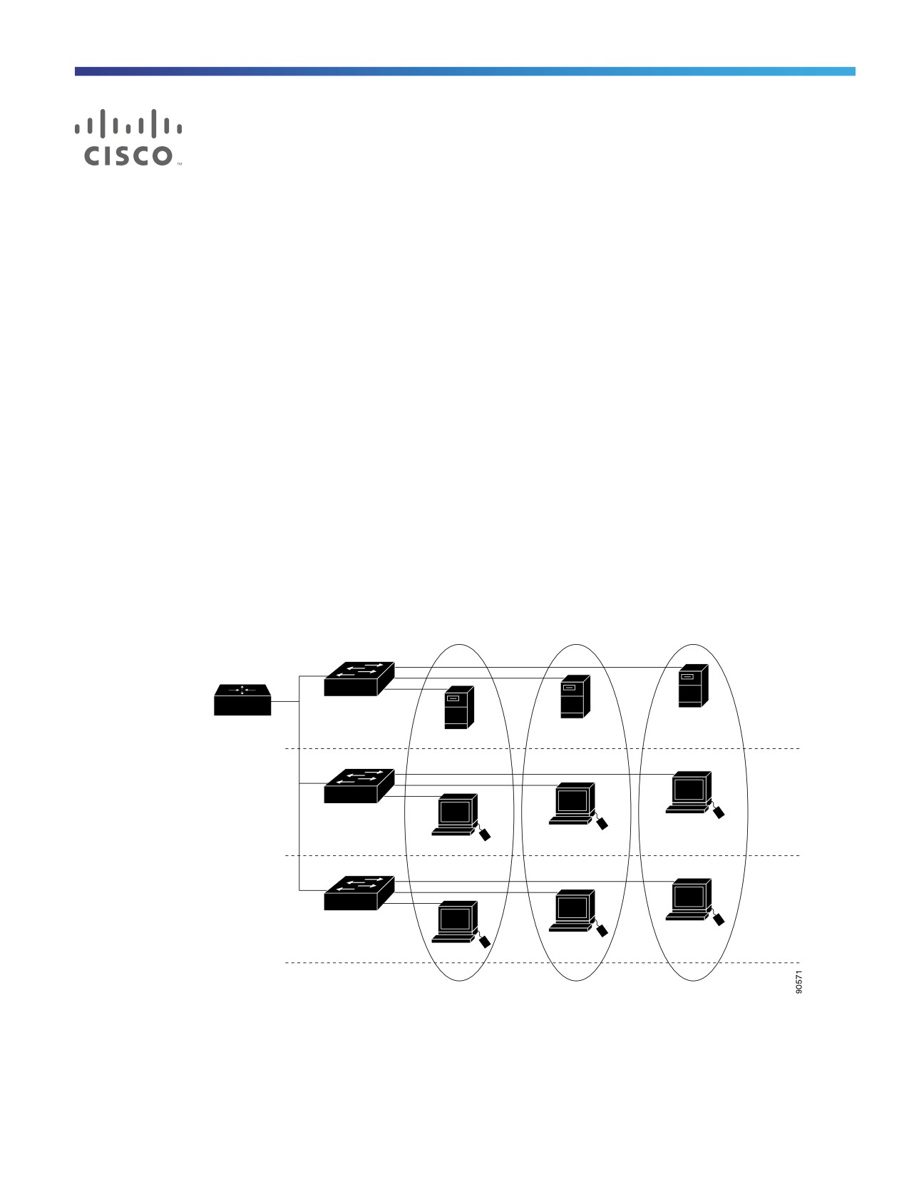
A VLAN is a switched network that is logically segmented by function, project team, or application, without regard to the
physical locations of the users. VLANs have the same attributes as physical LANs, but you can group end stations even
if they are not physically located on the same LAN segment. Any switch port can belong to a VLAN, and unicast,
broadcast, and multicast packets are forwarded and flooded only to end stations in the VLAN. Each VLAN is considered
a logical network, and packets destined for stations that do not belong to the VLAN must be forwarded through a router
or a switch supporting fallback bridging, as shown in Figure 29 on page 289. Because a VLAN is considered a separate
logical network, it contains its own bridge Management Information Base (MIB) information and can support its own
implementation of spanning tree. See Configuring STP, page 333
Note: Before you create VLANs, you must decide whether to use VLAN Trunking Protocol (VTP) to maintain global VLAN
configuration for your network.
Figure 29
VLANs as Logically Defined Networks
Engineering
Marketing
Accounting
VLAN
VLAN
VLAN
Cisco router
Floor 3
Gigabit
Ethernet
Floor 2
Floor 1
VLANs are often associated with IP subnetworks. For example, all the end stations in a particular IP subnet belong to the
same VLAN. Interface VLAN membership on the switch is assigned manually on an interface-by-interface basis. When
you assign switch interfaces to VLANs by using this method, it is known as interface-based, or static, VLAN membership.
289
Configuring VLANs
VLANs
Traffic between VLANs must be routed or fallback bridged. The switch can route traffic between VLANs by using switch
virtual interfaces (SVIs). An SVI must be explicitly configured and assigned an IP address to route traffic between VLANs.
Note: If you plan to configure many VLANs on the switch and to not enable routing, you can use the sdm prefer vlan
global configuration command to set the Switch Database Management (sdm) feature to the VLAN template, which
configures system resources to support the maximum number of unicast MAC addresses. For more information on the
SDM templates, see Configuring SDM Templates, page 137
Supported VLANs
The switch supports VLANs in VTP client, server, and transparent modes. VLANs are identified by a number from 1 to
4096. VLAN IDs 1002 through 1005 are reserved for Token Ring and FDDI VLANs.
VTP version 1 and version 2 support only normal-range VLANs (VLAN IDs 1 to 1005). In these versions, the switch must
be in VTP transparent mode when you create VLAN IDs from 1006 to 4096.
This release supports VTP version 3. VTP version 3 supports the entire VLAN range (VLANs 1 to 4096). Extended range
VLANs (VLANs 1006 to 4096) are supported only in VTP version 3. You cannot convert from VTP version 3 to VTP version
2 if extended VLANs are configured in the domain.
Although the switch supports a total of 1005 (normal range and extended range) VLANs, the number of routed ports,
SVIs, and other configured features affects the use of the switch hardware.
The switch supports per-VLAN spanning-tree plus (PVST+) or rapid PVST+ with a maximum of 128 spanning-tree
instances. One spanning-tree instance is allowed per VLAN. See Normal-Range VLAN Configuration Guidelines,
page 293 for more information about the number of spanning-tree instances and the number of VLANs.
VLAN Port Membership Modes
You configure a port to belong to a VLAN by assigning a membership mode that specifies the kind of traffic the port
carries and the number of VLANs to which it can belong. Table 33 on page 291 lists the membership modes and
membership and VTP characteristics.
290

Configuring VLANs
VLANs
Table 33
Port Membership Modes and Characteristics
Membership Mode
VLAN Membership Characteristics
VTP Characteristics
Static-access
A static-access port can belong to one VLAN and is
VTP is not required. If you do not want VTP
manually assigned to that VLAN.
to globally propagate information, set the
VTP mode to transparent. To participate in
For more information, see Assigning Static-Access Ports
VTP, there must be at least one trunk port
to a VLAN, page 303.
on the switch connected to a trunk port of
a second switch.
Trunk (ISL or
A trunk port is a member of all VLANs by default, including
VTP is recommended but not required.
IEEE 802.1Q)
extended-range VLANs, but membership can be limited
VTP maintains VLAN configuration
by configuring the allowed-VLAN list. You can also modify
consistency by managing the addition,
the pruning-eligible list to block flooded traffic to VLANs
deletion, and renaming of VLANs on a
on trunk ports that are included in the list.
network-wide basis. VTP exchanges VLAN
configuration messages with other
For information about configuring trunk ports, see
switches over trunk links.
Configuring an Ethernet Interface as a Trunk Port,
page 304.
Dynamic access
A dynamic-access port can belong to one VLAN and is
VTP is required.
dynamically assigned by a VMPS (VLAN Membership
Policy Server). The VMPS can be a Catalyst 5000 or
Configure the VMPS and the client with the
Catalyst 6500 series switch, for example, but never an
same VTP domain name.
IE 2000 switch. The IE 2000 switch is a VMPS client.
To participate in VTP, at least one trunk port
You can have dynamic-access ports and trunk ports on
on the switch must be connected to a trunk
the same switch, but you must connect the
port of a second switch.
dynamic-access port to an end station or hub and not to
another switch.
For configuration information, see Configuring
Dynamic-Access Ports on VMPS Clients, page 308.
Voice VLAN
A voice VLAN port is an access port attached to a Cisco
VTP is not required; it has no effect on a
IP Phone, configured to use one VLAN for voice traffic and
voice VLAN.
another VLAN for data traffic from a device attached to the
phone.
For more information about voice VLAN ports, see
Configuring Voice VLAN, page 327
For more detailed definitions of access and trunk modes and their functions, see Table 35 on page 296.
When a port belongs to a VLAN, the switch learns and manages the addresses associated with the port on a per-VLAN
basis. For more information, see Changing the Address Aging Time, page 115.
Normal-Range VLANs
Normal-range VLANs are VLANs with VLAN IDs 1 to 1005. If the switch is in VTP server or VTP transparent mode, you
can add, modify or remove configurations for VLANs 2 to 1001 in the VLAN database. (VLAN IDs 1 and 1002 to 1005
are automatically created and cannot be removed.)
Configurations for VLAN IDs 1 to 1005 are written to the vlan.dat file (VLAN database), and you can display them by
entering the show vlan privileged EXEC command. The vlan.dat file is stored in flash memory.
Caution: You can cause inconsistency in the VLAN database if you attempt to manually delete the vlan.dat file. If you
want to modify the VLAN configuration, use the commands described in these sections.
291
Configuring VLANs
VLANs
You use the interface configuration mode to define the port membership mode and to add and remove ports from VLANs.
The results of these commands are written to the running-configuration file, and you can display the file by entering the
show running-config privileged EXEC command.
You can set these parameters when you create a new normal-range VLAN or modify an existing VLAN in the VLAN
database:
VLAN ID
VLAN name
VLAN type (Ethernet, Fiber Distributed Data Interface [FDDI], FDDI network entity title [NET], TrBRF, or TrCRF, Token
Ring, Token Ring-Net)
VLAN state (active or suspended)
Maximum transmission unit (MTU) for the VLAN
Security Association Identifier (SAID)
Bridge identification number for TrBRF VLANs
Ring number for FDDI and TrCRF VLANs
Parent VLAN number for TrCRF VLANs
Spanning Tree Protocol (STP) type for TrCRF VLANs
VLAN number to use when translating from one VLAN type to another
You configure VLANs in vlan global configuration command by entering a VLAN ID. Enter a new VLAN ID to create a
VLAN, or enter an existing VLAN ID to modify that VLAN. You can use the default VLAN configuration (Table 34 on
page 294) or enter multiple commands to configure the VLAN. When you have finished the configuration, you must exit
VLAN configuration mode for the configuration to take effect. To display the VLAN configuration, enter the show vlan
privileged EXEC command.
The configurations of VLAN IDs 1 to 1005 are always saved in the VLAN database (vlan.dat file). If the VTP mode is
transparent, they are also saved in the switch running configuration file. You can enter the copy running-config
startup-config privileged EXEC command to save the configuration in the startup configuration file. To display the VLAN
configuration, enter the show vlan privileged EXEC command.
When you save VLAN and VTP information (including extended-range VLAN configuration information) in the startup
configuration file and reboot the switch, the switch configuration is selected as follows:
If the VTP mode is transparent in the startup configuration, and the VLAN database and the VTP domain name from
the VLAN database matches that in the startup configuration file, the VLAN database is ignored (cleared), and the
VTP and VLAN configurations in the startup configuration file are used. The VLAN database revision number remains
unchanged in the VLAN database.
If the VTP mode or domain name in the startup configuration does not match the VLAN database, the domain name
and VTP mode and configuration for the first 1005 VLANs use the VLAN database information.
In VTP versions 1 and 2, if VTP mode is server, the domain name and VLAN configuration for only the first 1005
VLANs use the VLAN database information. VTP version 3 also supports VLANs 1006 to 4096.
Token Ring VLANs
Although the switch does not support Token Ring connections, a remote device such as a Catalyst 6500 series switch
with Token Ring connections could be managed from one of the supported switches. Switches running VTP Version 2
advertise information about these Token Ring VLANs:
Token Ring TrBRF VLANs
292
Configuring VLANs
VLANs
Token Ring TrCRF VLANs
For more information on configuring Token Ring VLANs, see the Catalyst 6500 Series Software Configuration Guide.
Normal-Range VLAN Configuration Guidelines
Follow these guidelines when creating and modifying normal-range VLANs in your network:
The switch supports 1005 VLANs in VTP client, server, and transparent modes.
Normal-range VLANs are identified with a number between 1 and 1001. VLAN numbers 1002 through 1005 are
reserved for Token Ring and FDDI VLANs.
VLAN configuration for VLANs 1 to 1005 are always saved in the VLAN database. If the VTP mode is transparent,
VTP and VLAN configuration are also saved in the switch running configuration file.
With VTP versions 1 and 2, the switch supports VLAN IDs 1006 through 4096 only in VTP transparent mode (VTP
disabled). These are extended-range VLANs and configuration options are limited. Extended-range VLANs created
in VTP transparent mode are not saved in the VLAN database and are not propagated. VTP version 3 supports
extended range VLAN (VLANs 1006 to 4096) database propagation. If extended VLANs are configured, you cannot
convert from VTP version 3 to version 1 or 2. See Creating an Extended-Range VLAN, page 303.
Before you can create a VLAN, the switch must be in VTP server mode or VTP transparent mode. If the switch is a
VTP server, you must define a VTP domain or VTP will not function.
The switch does not support Token Ring or FDDI media. The switch does not forward FDDI, FDDI-Net, TrCRF, or
TrBRF traffic, but it does propagate the VLAN configuration through VTP.
The switch supports 128 spanning-tree instances. If a switch has more active VLANs than supported spanning-tree
instances, spanning tree can be enabled on 128 VLANs and is disabled on the remaining VLANs. If you have already
used all available spanning-tree instances on a switch, adding another VLAN anywhere in the VTP domain creates
a VLAN on that switch that is not running spanning-tree. If you have the default allowed list on the trunk ports of that
switch (which is to allow all VLANs), the new VLAN is carried on all trunk ports. Depending on the topology of the
network, this could create a loop in the new VLAN that would not be broken, particularly if there are several adjacent
switches that all have run out of spanning-tree instances. You can prevent this possibility by setting allowed lists on
the trunk ports of switches that have used up their allocation of spanning-tree instances.
If the number of VLANs on the switch exceeds the number of supported spanning-tree instances, we recommend
that you configure the IEEE 802.1s Multiple STP (MSTP) on your switch to map multiple VLANs to a single
spanning-tree instance. For more information about MSTP, see Configuring MSTP, page 351
Default Ethernet VLAN Configuration
Note: The switch supports Ethernet interfaces exclusively. Because FDDI and Token Ring VLANs are not locally
supported, you only configure FDDI and Token Ring media-specific characteristics for VTP global advertisements to other
switches.
293

Configuring VLANs
VLANs
Table 34
Ethernet VLAN Defaults and Ranges
Parameter
Default
Range
VLAN ID
1
1 to 4096.
Note: Extended-range VLANs (VLAN IDs
1006 to 4096) are only saved in the VLAN
database in VTP version 3.
VLAN name
VLANxxxx, where xxxx represents four numeric
No range
digits (including leading zeros) equal to the VLAN ID
number
IEEE 802.10 SAID
100001 (100000 plus the VLAN ID)
1 to 4294967294
MTU size
1500
1500 to 18190
Translational bridge 1
0
0 to 1005
Translational bridge 2
0
0 to 1005
VLAN state
active
active, suspend
Remote SPAN
disabled
enabled, disabled
Ethernet VLANs
Each Ethernet VLAN in the VLAN database has a unique, 4-digit ID that can be a number from 1 to 1001. VLAN IDs 1002
to 1005 are reserved for Token Ring and FDDI VLANs. To create a normal-range VLAN to be added to the VLAN database,
assign a number and name to the VLAN.
Note: With VTP version 1 and 2, if the switch is in VTP transparent mode, you can assign VLAN IDs greater than 1006,
but they are not added to the VLAN database. See Creating an Extended-Range VLAN, page 303.
For the list of default parameters that are assigned when you add a VLAN, see Normal-Range VLANs, page 291.
VLAN Removal
When you delete a VLAN from a switch that is in VTP server mode, the VLAN is removed from the VLAN database for all
switches in the VTP domain. When you delete a VLAN from a switch that is in VTP transparent mode, the VLAN is deleted
only on that specific switch.
You cannot delete the default VLANs for the different media types: Ethernet VLAN 1 and FDDI or Token Ring VLANs 1002
to 1005.
Caution: When you delete a VLAN, any ports assigned to that VLAN become inactive. They remain associated with
the VLAN (and thus inactive) until you assign them to a new VLAN.
Static-Access Ports for a VLAN
You can assign a static-access port to a VLAN without having VTP globally propagate VLAN configuration information by
disabling VTP (VTP transparent mode).
If you are assigning a port on a cluster member switch to a VLAN, first use the rcommand privileged EXEC command to
log in to the cluster member switch.
Note: If you assign an interface to a VLAN that does not exist, the new VLAN is created. (See Creating or Modifying an
Ethernet VLAN, page 302.)
294
Configuring VLANs
VLANs
Extended-Range VLANs
With VTP version 1 and version 2, when the switch is in VTP transparent mode (VTP disabled), you can create
extended-range VLANs (in the range 1006 to 4096). VTP version supports extended-range VLANs in server or
transparent move. Extended-range VLANs enable service providers to extend their infrastructure to a greater number of
customers. The extended-range VLAN IDs are allowed for any switchport commands that allow VLAN IDs.
With VTP version 1 or 2, extended-range VLAN configurations are not stored in the VLAN database, but because VTP
mode is transparent, they are stored in the switch running configuration file, and you can save the configuration in the
startup configuration file by using the copy running-config startup-config privileged EXEC command. Extended-range
VLANs created in VTP version 3 are stored in the VLAN database.
Default VLAN Configuration
See Table 34 on page 294 for the default configuration for Ethernet VLANs. You can change only the MTU size, private
VLAN, and the remote SPAN configuration state on extended-range VLANs; all other characteristics must remain at the
default state.
Extended-Range VLAN Configuration Guidelines
Follow these guidelines when creating extended-range VLANs:
VLAN IDs in the extended range are not saved in the VLAN database and are not recognized by VTP unless the switch
is running VTP version 3.
You cannot include extended-range VLANs in the pruning eligible range.
In VTP version 1 and 2, a switch must be in VTP transparent mode when you create extended-range VLANs. If VTP
mode is server or client, an error message is generated, and the extended-range VLAN is rejected. VTP version 3
supports extended VLANs in server and transparent modes.
For VTP version 1 or 2, you can set the VTP mode to transparent in global configuration mode. See Adding a VTP
Client Switch to a VTP Domain, page 321. You should save this configuration to the startup configuration so that the
switch boots up in VTP transparent mode. Otherwise, you lose the extended-range VLAN configuration if the switch
resets. If you create extended-range VLANs in VTP version 3, you cannot convert to VTP version 1 or 2.
STP is enabled by default on extended-range VLANs, but you can disable it by using the no spanning-tree vlan
vlan-id global configuration command. When the maximum number of spanning-tree instances are on the switch,
spanning tree is disabled on any newly created VLANs. If the number of VLANs on the switch exceeds the maximum
number of spanning-tree instances, we recommend that you configure the IEEE 802.1s Multiple STP (MSTP) on your
switch to map multiple VLANs to a single spanning-tree instance.
Each routed port on the switch creates an internal VLAN for its use. These internal VLANs use extended-range VLAN
numbers, and the internal VLAN ID cannot be used for an extended-range VLAN. If you try to create an
extended-range VLAN with a VLAN ID that is already allocated as an internal VLAN, an error message is generated,
and the command is rejected.
— Because internal VLAN IDs are in the lower part of the extended range, we recommend that you create
extended-range VLANs beginning from the highest number (4096) and moving to the lowest (1006) to reduce
the possibility of using an internal VLAN ID.
— Before configuring extended-range VLANs, enter the show vlan internal usage privileged EXEC command to
see which VLANs have been allocated as internal VLANs.
— If necessary, you can shut down the routed port assigned to the internal VLAN, which frees up the internal VLAN,
and then create the extended-range VLAN and re-enable the port, which then uses another VLAN as its internal
VLAN. See Creating an Extended-Range VLAN with an Internal VLAN ID, page 304.
295

Configuring VLANs
VLANs
Although the switch supports a total of 1005 (normal-range and extended-range) VLANs, the number of routed
ports, SVIs, and other configured features affects the use of the switch hardware. If you try to create an
extended-range VLAN and there are not enough hardware resources available, an error message is generated, and
the extended-range VLAN is rejected.
VLAN Trunks
Trunking Overview
A trunk is a point-to-point link between one or more Ethernet switch interfaces and another networking device such as
a router or a switch. Ethernet trunks carry the traffic of multiple VLANs over a single link, and you can extend the VLANs
across an entire network.
You can configure a trunk on a single Ethernet interface or on an EtherChannel bundle.
Ethernet trunk interfaces support different trunking modes (see Table 35 on page 296). You can set an interface as
trunking or nontrunking or to negotiate trunking with the neighboring interface. To autonegotiate trunking, the interfaces
must be in the same VTP domain.
Trunk negotiation is managed by the Dynamic Trunking Protocol (DTP), which is a Point-to-Point Protocol. However,
some internetworking devices might forward DTP frames improperly, which could cause misconfigurations.
To avoid this, you should configure interfaces connected to devices that do not support DTP to not forward DTP frames,
that is, to turn off DTP.
If you do not intend to trunk across those links, use the switchport mode access interface configuration command
to disable trunking.
To enable trunking to a device that does not support DTP, use the switchport mode trunk and switchport
nonegotiate interface configuration commands to cause the interface to become a trunk but to not generate DTP
frames.
Table 35
Layer 2 Interface Modes
Mode
Function
switchport mode access
Puts the interface (access port) into permanent nontrunking mode and negotiates to
convert the link into a nontrunk link. The interface becomes a nontrunk interface
regardless of whether or not the neighboring interface is a trunk interface.
switchport mode dynamic auto
Makes the interface able to convert the link to a trunk link. The interface becomes a trunk
interface if the neighboring interface is set to trunk or desirable mode. The default switch
port mode for all Ethernet interfaces is dynamic auto.
switchport mode dynamic
Makes the interface actively attempt to convert the link to a trunk link. The interface
desirable
becomes a trunk interface if the neighboring interface is set to trunk, desirable, or auto
mode.
switchport mode trunk
Puts the interface into permanent trunking mode and negotiates to convert the
neighboring link into a trunk link. The interface becomes a trunk interface even if the
neighboring interface is not a trunk interface.
switchport nonegotiate
Prevents the interface from generating DTP frames. You can use this command only when
the interface switchport mode is access or trunk. You must manually configure the
neighboring interface as a trunk interface to establish a trunk link.
IEEE 802.1Q Configuration Guidelines
The IEEE 802.1Q trunks impose these restrictions on the trunking strategy for a network:
296

Configuring VLANs
VLANs
In a network of Cisco switches connected through IEEE 802.1Q trunks, the switches maintain one spanning-tree
instance for each VLAN allowed on the trunks. Non-Cisco devices might support one spanning-tree instance for all
VLANs.
When you connect a Cisco switch to a non-Cisco device through an IEEE 802.1Q trunk, the Cisco switch combines
the spanning-tree instance of the VLAN of the trunk with the spanning-tree instance of the non-Cisco IEEE 802.1Q
switch. However, spanning-tree information for each VLAN is maintained by Cisco switches separated by a cloud of
non-Cisco IEEE 802.1Q switches. The non-Cisco IEEE 802.1Q cloud separating the Cisco switches is treated as a
single trunk link between the switches.
Make sure the native VLAN for an IEEE 802.1Q trunk is the same on both ends of the trunk link. If the native VLAN
on one end of the trunk is different from the native VLAN on the other end, spanning-tree loops might result.
Disabling spanning tree on the native VLAN of an IEEE 802.1Q trunk without disabling spanning tree on every VLAN
in the network can potentially cause spanning-tree loops. We recommend that you leave spanning tree enabled on
the native VLAN of an IEEE 802.1Q trunk or disable spanning tree on every VLAN in the network. Make sure your
network is loop-free before you disable spanning tree.
Default Layer 2 Ethernet Interface VLAN Settings
Feature
Default Setting
Interface mode
switchport mode dynamic auto
Allowed VLAN range
VLANs 1 to 4096
VLAN range eligible for pruning
VLANs 2 to 1001
Default VLAN (for access ports)
VLAN 1
Native VLAN (for IEEE 802.1Q trunks)
VLAN 1
Ethernet Interface as a Trunk Port
Because trunk ports send and receive VTP advertisements, to use VTP you must ensure that at least one trunk port is
configured on the switch and that this trunk port is connected to the trunk port of a second switch. Otherwise, the switch
cannot receive any VTP advertisements.
Note: By default, an interface is in Layer 2 mode. The default mode for Layer 2 interfaces is switchport mode dynamic
auto. If the neighboring interface supports trunking and is configured to allow trunking, the link is a Layer 2 trunk or, if
the interface is in Layer 3 mode, it becomes a Layer 2 trunk when you enter the switchport interface configuration
command.
Trunking Interaction with Other Features
Trunking interacts with other features in these ways:
A trunk port cannot be a secure port.
A trunk port cannot be a tunnel port.
Trunk ports can be grouped into EtherChannel port groups, but all trunks in the group must have the same
configuration. When a group is first created, all ports follow the parameters set for the first port to be added to the
group. If you change the configuration of one of these parameters, the switch propagates the setting you entered to
all ports in the group:
— Allowed-VLAN list.
— STP port priority for each VLAN.
297
Configuring VLANs
VLANs
— STP Port Fast setting.
— Trunk status. If one port in a port group ceases to be a trunk, all ports cease to be trunks.
We recommend that you configure no more than 24 trunk ports in PVST mode and no more than 40 trunk ports in
MST mode.
If you try to enable IEEE 802.1x on a trunk port, an error message appears, and IEEE 802.1x is not enabled. If you try
to change the mode of an IEEE 802.1x-enabled port to trunk, the port mode is not changed.
A port in dynamic mode can negotiate with its neighbor to become a trunk port. If you try to enable IEEE 802.1x on
a dynamic port, an error message appears, and IEEE 802.1x is not enabled. If you try to change the mode of an IEEE
802.1x-enabled port to dynamic, the port mode is not changed.
Allowed VLANs on a Trunk
By default, a trunk port sends traffic to and receives traffic from all VLANs. All VLAN IDs, 1 to 4096, are allowed on each
trunk. However, you can remove VLANs from the allowed list, preventing traffic from those VLANs from passing over the
trunk. To restrict the traffic a trunk carries, use the switchport trunk allowed vlan remove vlan-list interface
configuration command to remove specific VLANs from the allowed list.
Note: VLAN 1 is the default VLAN on all trunk ports in all Cisco switches, and it has previously been a requirement that
VLAN 1 always be enabled on every trunk link. You can use the VLAN 1 minimization feature to disable VLAN 1 on any
individual VLAN trunk link so that no user traffic (including spanning-tree advertisements) is sent or received on VLAN 1.
To reduce the risk of spanning-tree loops or storms, you can disable VLAN 1 on any individual VLAN trunk port by
removing VLAN 1 from the allowed list. When you remove VLAN 1 from a trunk port, the interface continues to send and
receive management traffic, for example, Cisco Discovery Protocol (CDP), Port Aggregation Protocol (PAgP), Link
Aggregation Control Protocol (LACP), DTP, and VTP in VLAN 1.
If a trunk port with VLAN 1 disabled is converted to a nontrunk port, it is added to the access VLAN. If the access VLAN
is set to 1, the port will be added to VLAN 1, regardless of the switchport trunk allowed setting. The same situation
applies for any VLAN that has been disabled on the port.
A trunk port can become a member of a VLAN if the VLAN is enabled, if VTP knows of the VLAN, and if the VLAN is in
the allowed list for the port. When VTP detects a newly enabled VLAN and the VLAN is in the allowed list for a trunk port,
the trunk port automatically becomes a member of the enabled VLAN. When VTP detects a new VLAN and the VLAN is
not in the allowed list for a trunk port, the trunk port does not become a member of the new VLAN.
Native VLAN for Untagged Traffic
A trunk port configured with IEEE 802.1Q tagging can receive both tagged and untagged traffic. By default, the switch
forwards untagged traffic in the native VLAN configured for the port. The native VLAN is VLAN 1 by default.
Note: The native VLAN can be assigned any VLAN ID.
For information about IEEE 802.1Q configuration issues, see IEEE 802.1Q Configuration Guidelines, page 296.
Load Sharing Using Trunk Ports
Load sharing divides the bandwidth supplied by parallel trunks connecting switches. To avoid loops, STP normally blocks
all but one parallel link between switches. Using load sharing, you divide the traffic between the links according to which
VLAN the traffic belongs.
You configure load sharing on trunk ports by using STP port priorities or STP path costs. For load sharing using STP port
priorities, both load-sharing links must be connected to the same switch. For load sharing using STP path costs, each
load-sharing link can be connected to the same switch or to two different switches.
298
Configuring VLANs
VLANs
Load Sharing Using STP Port Priorities
When two ports on the same switch form a loop, the switch uses the STP port priority to decide which port is enabled
and which port is in a blocking state. You can set the priorities on a parallel trunk port so that the port carries all the traffic
for a given VLAN. The trunk port with the higher priority (lower values) for a VLAN is forwarding traffic for that VLAN. The
trunk port with the lower priority (higher values) for the same VLAN remains in a blocking state for that VLAN. One trunk
port sends or receives all traffic for the VLAN.
Figure 30 on page 299 shows two trunks connecting supported switches. In this example, the switches are configured
as follows:
VLANs 8 through 10 are assigned a port priority of 16 on Trunk 1.
VLANs 3 through 6 retain the default port priority of 128 on Trunk 1.
VLANs 3 through 6 are assigned a port priority of 16 on Trunk 2.
VLANs 8 through 10 retain the default port priority of 128 on Trunk 2.
In this way, Trunk 1 carries traffic for VLANs 8 through 10, and Trunk 2 carries traffic for VLANs 3 through 6. If the active
trunk fails, the trunk with the lower priority takes over and carries the traffic for all of the VLANs. No duplication of traffic
occurs over any trunk port.
Figure 30
Load Sharing by Using STP Port Priorities
Switch A
Trunk 1
Trunk 2
VLANs 8 - 10 (priority 16)
VLANs 3 - 6 (priority 16)
VLANs 3 - 6 (priority 128)
VLANs 8 - 10 (priority 128)
Switch B
Load Sharing Using STP Path Cost
You can configure parallel trunks to share VLAN traffic by setting different path costs on a trunk and associating the path
costs with different sets of VLANs, blocking different ports for different VLANs. The VLANs keep the traffic separate and
maintain redundancy in the event of a lost link.
In Figure 31 on page 300, Trunk ports 1 and 2 are configured as 100BASE-T ports. These VLAN path costs are assigned:
VLANs 2 through 4 are assigned a path cost of 30 on Trunk port 1.
VLANs 8 through 10 retain the default 100BASE-T path cost on Trunk port 1 of 19.
VLANs 8 through 10 are assigned a path cost of 30 on Trunk port 2.
VLANs 2 through 4 retain the default 100BASE-T path cost on Trunk port 2 of 19.
299
Configuring VLANs
VLANs
Figure 31
Load-Sharing Trunks with Traffic Distributed by Path Cost
Switch A
Trunk port 1
Trunk port 2
VLANs 2 - 4 (path cost 30)
VLANs 8 - 10 (path cost 30)
VLANs 8 - 10 (path cost 19)
VLANs 2 - 4 (path cost 19)
Switch B
See Configuring Load Sharing Using STP Path Cost, page 306.
VMPS
The VLAN Query Protocol (VQP) is used to support dynamic-access ports, which are not permanently assigned to a
VLAN, but give VLAN assignments based on the MAC source addresses seen on the port. Each time an unknown MAC
address is seen, the switch sends a VQP query to a remote VMPS; the query includes the newly seen MAC address and
the port on which it was seen. The VMPS responds with a VLAN assignment for the port. The switch cannot be a VMPS
server but can act as a client to the VMPS and communicate with it through VQP.
Each time the client switch receives the MAC address of a new host, it sends a VQP query to the VMPS. When the VMPS
receives this query, it searches its database for a MAC-address-to-VLAN mapping. The server response is based on this
mapping and whether or not the server is in open or secure mode. In secure mode, the server shuts down the port when
an illegal host is detected. In open mode, the server simply denies the host access to the port.
If the port is currently unassigned (that is, it does not yet have a VLAN assignment), the VMPS provides one of these
responses:
If the host is allowed on the port, the VMPS sends the client a vlan-assignment response containing the assigned
VLAN name and allowing access to the host.
If the host is not allowed on the port and the VMPS is in open mode, the VMPS sends an access-denied response.
If the VLAN is not allowed on the port and the VMPS is in secure mode, the VMPS sends a port-shutdown response.
If the port already has a VLAN assignment, the VMPS provides one of these responses:
If the VLAN in the database matches the current VLAN on the port, the VMPS sends a success response, allowing
access to the host.
If the VLAN in the database does not match the current VLAN on the port and active hosts exist on the port, the
VMPS sends an access-denied or a port-shutdown response, depending on the secure mode of the VMPS.
If the switch receives an access-denied response from the VMPS, it continues to block traffic to and from the host MAC
address. The switch continues to monitor the packets directed to the port and sends a query to the VMPS when it
identifies a new host address. If the switch receives a port-shutdown response from the VMPS, it disables the port. The
port must be manually reenabled by using Network Assistant, the CLI or SNMP.
Dynamic-Access Port VLAN Membership
A dynamic-access port can belong to only one VLAN with an ID from 1 to 4096. When the link comes up, the switch
does not forward traffic to or from this port until the VMPS provides the VLAN assignment. The VMPS receives the source
MAC address from the first packet of a new host connected to the dynamic-access port and attempts to match the MAC
address to a VLAN in the VMPS database.
300

Configuring VLANs
VLANs
If there is a match, the VMPS sends the VLAN number for that port. If the client switch was not previously configured, it
uses the domain name from the first VTP packet it receives on its trunk port from the VMPS. If the client switch was
previously configured, it includes its domain name in the query packet to the VMPS to obtain its VLAN number. The VMPS
verifies that the domain name in the packet matches its own domain name before accepting the request and responds
to the client with the assigned VLAN number for the client. If there is no match, the VMPS either denies the request or
shuts down the port (depending on the VMPS secure mode setting).
Multiple hosts (MAC addresses) can be active on a dynamic-access port if they are all in the same VLAN; however, the
VMPS shuts down a dynamic-access port if more than 20 hosts are active on the port.
If the link goes down on a dynamic-access port, the port returns to an isolated state and does not belong to a VLAN. Any
hosts that come online through the port are checked again through the VQP with the VMPS before the port is assigned
to a VLAN.
Dynamic-access ports can be used for direct host connections, or they can connect to a network. A maximum of 20 MAC
addresses are allowed per port on the switch. A dynamic-access port can belong to only one VLAN at a time, but the
VLAN can change over time, depending on the MAC addresses seen.
Default VMPS Client Settings
Feature
Default Setting
VMPS domain server
None
VMPS reconfirm interval
60 minutes
VMPS server retry count
3
Dynamic-access ports
None configured
VMPS Configuration Guidelines
These guidelines and restrictions apply to dynamic-access port VLAN membership:
You should configure the VMPS before you configure ports as dynamic-access ports.
When you configure a port as a dynamic-access port, the spanning-tree Port Fast feature is automatically enabled
for that port. The Port Fast mode accelerates the process of bringing the port into the forwarding state.
IEEE 802.1x ports cannot be configured as dynamic-access ports. If you try to enable IEEE 802.1x on a
dynamic-access (VQP) port, an error message appears, and IEEE 802.1x is not enabled. If you try to change an IEEE
802.1x-enabled port to dynamic VLAN assignment, an error message appears, and the VLAN configuration is not
changed.
Trunk ports cannot be dynamic-access ports, but you can enter the switchport access vlan dynamic interface
configuration command for a trunk port. In this case, the switch retains the setting and applies it if the port is later
configured as an access port.
You must turn off trunking on the port before the dynamic-access setting takes effect.
Dynamic-access ports cannot be monitor ports.
Secure ports cannot be dynamic-access ports. You must disable port security on a port before it becomes dynamic.
Private VLAN ports cannot be dynamic-access ports.
Dynamic-access ports cannot be members of an EtherChannel group.
Port channels cannot be configured as dynamic-access ports.
301

Configuring VLANs
How to Configure VLANs
A dynamic-access port can participate in fallback bridging.
The VTP management domain of the VMPS client and the VMPS server must be the same.
The VLAN configured on the VMPS server should not be a voice VLAN.
VMPS Reconfirmation Interval
VMPS clients periodically reconfirm the VLAN membership information received from the VMPS.You can set the number
of minutes after which reconfirmation occurs.
If you are configuring a member switch in a cluster, this parameter must be equal to or greater than the reconfirmation
setting on the command switch. You must also first use the rcommand privileged EXEC command to log in to the member
switch.
Dynamic-Access Port VLAN Membership
The VMPS shuts down a dynamic-access port under these conditions:
The VMPS is in secure mode, and it does not allow the host to connect to the port. The VMPS shuts down the port
to prevent the host from connecting to the network.
More than 20 active hosts reside on a dynamic-access port.
To reenable a disabled dynamic-access port, enter the shutdown interface configuration command followed by the no
shutdown interface configuration command.
How to Configure VLANs
Creating or Modifying an Ethernet VLAN
Command
Purpose
1.
configure terminal
Enters global configuration mode.
2.
vlan vlan-id
Enters a VLAN ID, and enters VLAN configuration mode.
Note: The available VLAN ID range for this command is 1 to 4096. For
information about adding VLAN IDs greater than 1005 (extended-range
VLANs), see Creating an Extended-Range VLAN, page 303.
3.
name vlan-name
(Optional) Enters a name for the VLAN. If no name is entered for the
VLAN, the default is to append the vlan-id with leading zeros to the
word VLAN. For example, VLAN0004 is a default VLAN name for VLAN
4.
4.
mtu mtu-size
(Optional) Changes the MTU size (or other VLAN characteristic).
5.
remote-span
(Optional) Configures the VLAN as the RSPAN VLAN for a remote SPAN
session.
Note: For more information on remote SPAN, see Configuring SPAN and
RSPAN, page 491
6.
end
Returns to privileged EXEC mode.
302

Configuring VLANs
How to Configure VLANs
Deleting a VLAN
Command
Purpose
1.
configure terminal
Enters global configuration mode.
2.
no vlan vlan-id
Removes the VLAN by entering the VLAN ID.
3.
end
Returns to privileged EXEC mode.
Assigning Static-Access Ports to a VLAN
Command
Purpose
1.
configure terminal
Enters global configuration mode
2.
interface interface-id
Enters the interface to be added to the VLAN.
3.
switchport mode access
Defines the VLAN membership mode for the port (Layer 2 access
port).
4.
switchport access vlan vlan-id
Assigns the port to a VLAN. Valid VLAN IDs are 1 to 4096.
5.
end
Returns to privileged EXEC mode.
Creating an Extended-Range VLAN
Command
Purpose
1.
configure terminal
Enters global configuration mode.
2.
vtp mode transparent
Configures the switch for VTP transparent mode and disables VTP.
Note: This step is not required for VTP version 3.
3.
vlan vlan-id
Enters an extended-range VLAN ID and enters VLAN configuration mode.
The range is 1006 to 4096.
4.
mtu mtu-size
(Optional) Modifies the VLAN by changing the MTU size.
Note: Although all VLAN commands appear in the CLI help, only the mtu
mtu-size, private-vlan, and remote-span commands are supported for
extended-range VLANs.
5.
remote-span
(Optional) Configures the VLAN as the RSPAN VLAN. See Configuring a
VLAN as an RSPAN VLAN, page 505.
6.
end
Returns to privileged EXEC mode.
303

Configuring VLANs
How to Configure VLANs
Creating an Extended-Range VLAN with an Internal VLAN ID
Command
Purpose
1.
show vlan internal usage
Displays the VLAN IDs being used internally by the switch. If the VLAN ID
that you want to use is an internal VLAN, the display shows the routed
port that is using the VLAN ID. Enter that port number in Step 3.
2.
configure terminal
Enters global configuration mode.
3.
interface interface-id
Specifies the interface ID for the routed port that is using the VLAN ID,
and enters interface configuration mode.
4.
shutdown
Shuts down the port to free the internal VLAN ID.
5.
exit
Returns to global configuration mode.
6.
vtp mode transparent
Sets the VTP mode to transparent for creating extended-range VLANs.
Note: This step is not required for VTP version 3.
7.
vlan vlan-id
Enters the new extended-range VLAN ID, and enters VLAN configuration
mode.
8.
exit
Exits from VLAN configuration mode, and returns to global configuration
mode.
9.
interface interface-id
Specifies the interface ID for the routed port that you shut down in Step
4, and enters interface configuration mode.
10.
no shutdown
Reenables the routed port. It will be assigned a new internal VLAN ID.
11.
end
Returns to privileged EXEC mode.
Configuring an Ethernet Interface as a Trunk Port
Command
Purpose
1.
configure terminal
Enters global configuration mode.
2.
interface interface-id
Specifies the port to be configured for trunking, and enters interface
configuration mode.
3.
switchport mode {dynamic {auto |
Configures the interface as a Layer 2 trunk (required only if the interface
desirable} | trunk}
is a Layer 2 access port or tunnel port or to specify the trunking mode).
dynamic auto—Sets the interface to a trunk link if the neighboring
interface is set to trunk or desirable mode. This is the default.
dynamic desirable—Sets the interface to a trunk link if the
neighboring interface is set to trunk, desirable, or auto mode.
trunk—Sets the interface in permanent trunking mode and negotiate
to convert the link to a trunk link even if the neighboring interface is
not a trunk interface.
4.
switchport access vlan vlan-id
(Optional) Specifies the default VLAN, which is used if the interface stops
trunking.
5.
switchport trunk native vlan vlan-id
Specifies the native VLAN for IEEE 802.1Q trunks.
6.
end
Returns to privileged EXEC mode.
304

Configuring VLANs
How to Configure VLANs
Defining the Allowed VLANs on a Trunk
Command
Purpose
1.
configure terminal
Enters global configuration mode.
2.
interface interface-id
Specifies the port to be configured, and enters interface configuration
mode.
3.
switchport mode trunk
Configures the interface as a VLAN trunk port.
4.
switchport trunk allowed vlan {add | all
(Optional) Configures the list of VLANs allowed on the trunk.
| except | remove} vlan-list
5.
end
Returns to privileged EXEC mode.
Changing the Pruning-Eligible List
Command
Purpose
1.
configure terminal
Enters global configuration mode.
2.
interface interface-id
Selects the trunk port for which VLANs should be pruned, and enters
interface configuration mode.
3.
switchport trunk pruning vlan {add |
Configures the list of VLANs allowed to be pruned from the trunk. (See
except | none | remove} vlan-list
VTP Pruning, page 318.)
[,vlan[,vlan[,,,]]
4.
end
Returns to privileged EXEC mode.
Configuring the Native VLAN for Untagged Traffic
Command
Purpose
1.
configure terminal
Enters global configuration mode.
2.
interface interface-id
Defines the interface that is configured as the IEEE 802.1Q trunk, and
enters interface configuration mode.
3.
switchport trunk native vlan vlan-id
Configures the VLAN that is sending and receiving untagged traffic
on the trunk port.
4.
end
Returns to privileged EXEC mode.
305