Kawasaki Robot Controller E Series. Reference Manual (2015) - page 12

6. Program Instructions
SLOAD/IF/ARC device number = file name, status variable
Function
Reads from external memory device, the file specified by the character string and loads it on
to the robot memory.
Parameter
Device number
Specifies where to display the current processing situation. Specify either 1 or 2:
1:Standard terminal (PC)
2:Teach pendant
When omitted, it is displayed where the program is executed.
File name
Specifies the file to load on to robot memory. Only one file can be specified.
Status variable
Specifying 0 for this parameter allows continuing program execution even when error occurs.
The error code is saved. When omitted, program execution stops at error occurrence.
Explanation
Loads on to robot memory the contents (program and variables) of the specified file.
Specifying a program with the same name as a program already in the robot memory results
in error, and no new program is read.
1. Specifying SLOAD/IF loads interface panel data.
2. Specifying SLOAD/ARC loads arc welding data.
When there is a step that is not readable in a program being loaded, error message and
message “Step format incorrect. (0: Comment-out the step and continue reading, 1: Delete
program and terminate) appears. When continuing by selecting “0”, modify the program
via editor after loading is completed.
[ NOTE ]
Pose variable, real variable, or a string variable with the same name as the
variable being read is over-written by the new data without any warning.
Example
SLOAD $str1
When $str1=”pallet.as”, loads content of file pallet.as.
SLOAD $str2
When $str2=”f3.pg”, loads contents of file f3.pg.
6-129
6. Program Instructions
6-130
7. System Switches
7.0 SYSTEM SWITCHES
㻌
This chapter describes the function of each system switch. For setting ON/OFF or checking
the status of switches, refer to the SWITCH, ON and OFF monitor commands/ program
instructions.
CP
Enables or disables continuous path (CP) function.
CHECK.HOLD
Enables or disables input of commands from the keyboard
when HOLD/RUN is in HOLD state.
CYCLE.STOP
Stops cycle with External HOLD.
MESSAGES
Enables or disables terminal output.
OX.PREOUT
Sets the timing of output signal generation.
PREFETCH.SIGINS
Enables or disables early processing of I/O signals in AS
programs.
QTOOL
Enables or disables tool transformation during block teaching.
RPS
Enables or disables the random selection of programs.
SCREEN
Control terminal display.
REP_ONCE
Sets if repeat cycle is done once or continuously.
STP_ONCE
Sets the execution as one step at a time or continuous.
AUTOSTART.PC
Enables the PC program to start automatically at control
power ON.
ERRSTART.PC
Determines if the selected PC program is executed when an
error occurs.
TRIGGER
Displays the ON/OFF status of
TRIGGER switch.
CS
Displays the ON/ OFF status of CYCLE START.
POWER
Displays the ON/ OFF status of the motor power.
RGSO
Displays the ON/OFF status of servoing.
TEACH_LOCK
Displays the ON/OFF status of
TEACH LOCK.
ERROR
Displays if the program is in error status or not.
REPEAT
Displays the status of
TEACH/REPEAT switch.
RUN
Displays the current HOLD/RUN state.
PNL_CYCST
Displays the ON/ OFF status of CYCLE START.
7-1
7. System Switches
PNL_MPOWER
Displays the ON/ OFF status of the motor power.
PNL_ERESET
Displays the ON/ OFF status of
ERRORRESET on operation
panel.
TPKEY_A
Displays the ON/ OFF status of
A key on teach pendant.
DISPIO_01
Changes the display mode of IO command.
HOLD.STEP
Enables display of the step in execution when the program is
held. (Option)
WS_COMPOFF
Changes the output timing of WS signal. (Option)
FLOWRATE
Changes from flow rate control mode to speed output mode
(and vice versa). (Option)
WS.ZERO
Changes the weld processing that is done when WS=0.㻌
(Option)
ABS.SPEED
Enables use of absolute speed.
SLOW_START
Enables or disables the slow start function.
AFTER.WAIT.TMR
Sets how timers begin in block step programs.
SF_OPEN_ERROR
Give error when safety fence is open
STAT_ON_KYBD
Displays status data on the keyboard screen.
WAITREL_AUTO
Displays the wait release popup window.
REP_ONCE.RPS_LAST
Selects the terminating step in repeat once operation.
Determines the pose where the DEST/#DEST function
DEST_CIRINT
returns.
Determines if the date is added to the program information or
PROGDATE
not.
Determines if confirmation message for inset is displayed or
INSERT_NO_CONFIRM
not.
Switches between enable/ disable of signal operation from
SIGMON_TEACH
signal monitor
Switches between enable/ disable of touch panel operation of
TOUCH.ENA
teach pendant repeat condition.
Switches between enable/ disable of touch panel operation of
TOUCHST.ENA
teach pendant status lamp.
Determines if slow speed is set automatically for teach or
TPSPEED.RESET
check speed.
Switches the collective reset function for external output signal
OXZERO
(OX).
IFAKEY
In I/F panel, switches the function to allow with A key.
7-2
7. System Switches
DISP.EXESTEP
Switches the step display at time of program execution
Switches enable/ disable of the file character code conversion
NO_SJISCONV
at time of save/ load
Determines if configuration change is allowed or not during
CONF_VARIABLE
linear motion
Determines whether SHIFT status is invalid when A key is
INVALID.TPKEY_S
pressed
Determines whether the information of the two A keys are
DIVIDE.TPKEY_S
allocated separately or not
Switches the number of signals to reset when signal 0 is
SIGRSTCONF
output
SINGULAR
Switches the enable/ disable of singular point check function.
USE_ISO8859_5
Switches the ASCII8 bit display font to Cyrillic font.
7-3
7. System Switches
CP
Function㻌
Enables or disables continuous path (CP) function.
Explanation㻌
This switch is used to turn ON (enable) or OFF (disable) the CP function. When this switch
is changed in a program, the CP function is enabled /disabled starting from the next motion.
The default setting for this switch is ON.
Example㻌
CP OFF
Disables the CP function.
CHECK. HOLD
Function㻌
Enables or disables the use of the keyboard to enter the EXECUTE, DO, STEP, MSTEP, and
CONTINUE commands when the HOLD/RUN state is in HOLD.
Explanation㻌
When this switch is ON, the following commands entered from the keyboard are accepted
only when HOLD/RUN is in HOLD. (The commands are accepted, but the motion does not
start unless HOLD/RUN is changed to RUN.)
EXECUTE, DO, STEP, MSTEP, CONTINUE
When this switch is OFF, the commands above are accepted regardless of the state of
HOLD/RUN. Operations not done by keyboard are not affected by this command. (If in
RUN state, the robot starts moving as soon as the command is input.)
Default setting is OFF.
7-4

7. System Switches
CYCLE. STOP
㻌
Function㻌
Determines whether or not to continue repeating the execution cycle after an HOLD is
applied.
Explanation㻌
When this switch is OFF, the robot stops when the external HOLD signal is input, but
CYCLE START remains ON. Therefore, when the external HOLD signal is turned OFF,
the robot resumes program execution.
When this switch is ON, the robot stops when the external HOLD signal is input, and
CYCLE START is turned OFF. Therefore, even if the external HOLD is released, CYCLE
START remains OFF, so the robot does not resume program execution. To resume program
execution, follow regular program execution procedures (i.e. press
A
+
CYCLE START on teach pendant).
This switch has effect only on external HOLD and not when HOLD/RUN state is changed to
HOLD. If HOLD/RUN is changed to HOLD, robot stops, but CYCLE START remains ON,
regardless of the condition of this system switch. The robot resumes program execution
when HOLD/RUN is changed to RUN.
Default setting is OFF.
㻌
MESSAGES
㻌
Function㻌
Enables or disables the output of message on the terminal.
Explanation㻌
When this switch is ON, the messages are displayed on the terminal when the PRINT or
TYPE command is used. When this switch is OFF, messages are not displayed on the
terminal.
Default setting is ON.
7-5
7. System Switches
OX. PREOUT
㻌
Function㻌
Determines the timing for turning ON/OFF OX signals in block step instruction.
Explanation㻌
When running programs taught by block step instructions and this switch is ON, the OX
signal taught for a given pose is turned ON as soon as the robot begins motion toward the
pose.
When this switch is OFF, the signal is not turned ON until the axes coincide with the pose
taught at that step.
Default setting is ON.
㻌
㻌
㻌
PREFETCH. SIGINS
㻌
Function㻌
Enables or disables early processing of signal input and output commands in AS programs.
Explanation㻌
When this switch is OFF, commands for signal input/ output and synchronization listed below
are not executed until the axis coincides with the pose taught to the current motion instruction.
SWAIT, SIGNAL, TWAIT, PULSE, DLYSIG, RUNMASK, RESET, BITS
When this switch is ON, all commands including the commands above are executed and the
program is processed up to the step before the next motion instruction as soon as the
movement towards a taught point starts.
Default setting is OFF.
7-6
7. System Switches
QTOOL
㻌
Function㻌
Enables or disables tool transformation during block teaching.
Explanation㻌
When this switch is ON, the following functions come into effect for the tool coordinates
being taught:
1. Automatic selection of the tool coordinates
(1) If the current step is taught in block teaching, the robot is moved according to the tool data
registered for the currently selected tool (1 - 9).
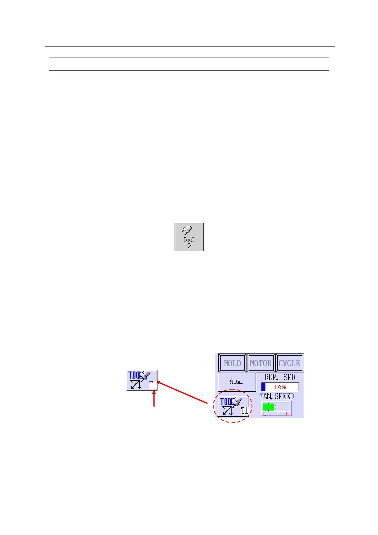
(2) If an AS language instruction is taught at the current step, the tool changes to the tool
specified by the button below. Therefore, when using only the tool taught by AS language,
turn this switch OFF.
(3)
(3) If nothing is taught yet in the current step, and the teach pendant is displaying the
auxiliary data screen, the robot is moved according to the tool coordinates registered as the
tool data for the tool (1 - 9) currently shown on screen.
(4) If nothing is taught yet in the current step and the teach pendant is not at the auxiliary data
screen, the tool coordinates remain unchanged.
2. The tool number currently effective is displayed in the status area, on the upper right corner
of the teach pendant screen.
The tool number is displayed here after “T”.
When this switch is OFF, the tool coordinates change when the TOOL command is executed,
or when the TOOL instruction or when a block instruction is executed within a program.
Default setting is ON.
7-7

7. System Switches
㻌
RPS
㻌
Function㻌
Enables or disables the random selection of programs (JMP, RPS).
Explanation㻌
When this switch is OFF, the EXTCALL instruction and JUMP/ END of the auxiliary data
are ignored.
Default setting is OFF.
㻌
SCREEN
㻌
Function㻌
Enables or disables scrolling of the screen.
Explanation㻌
If the switch is ON, the scrolling of the screen stops when the display is full. Press
Spacebar
to show the next page.
Default setting is ON.
7-8
7. System Switches
㻌
REP_ONCE
㻌
Function㻌
Determines whether the program is run one time or continuously.
Explanation㻌
When this switch is ON, the program runs one time.
When this switch is OFF, the program runs continuously.
Default setting is OFF.
㻌
STP_ ONCE
㻌
Function㻌
Determines whether the program steps are run one step at a time or continuously.
Explanation㻌
When this switch is ON, the program steps are run one step at a time.
When this switch is OFF, the program runs continuously through all the steps.
Default setting is OFF.
7-9
7. System Switches
㻌
AUTOSTART. PC
AUTOSTART2. PC
AUTOSTART3. PC
AUTOSTART4. PC
AUTOSTART5. PC
㻌
Function㻌
Determines if the selected PC program starts automatically when the control power is turned
ON.
Explanation㻌
When this switch is ON, the PC program named AUTOSTART.PC starts automatically when
the controller power is turned ON. Program AUTOSTART.PC should be created
beforehand. Five different PC programs can be selected to start automatically, each named
AUTOSTART.PC and AUTOSTART2.PC to AUTOSTART5.PC. Create a program named
accordingly and turn ON each corresponding switch to start the desired program.
Default setting is OFF.
㻌
[ NOTE ]
When this switch is turned ON but the corresponding program does not exist, an
error occurs and the message “Program does not exist” appears.
7-10
7. System Switches
ERRSTART. PC
㻻㼜㼠㼕㼛㼚㻌
Function㻌
Determines if the selected PC program is executed or not when an error occurs.
Explanation㻌
When this switch is ON, the PC program named ERRSTART.PC is automatically executed
when an error occurs. Create a PC program named ERRSTART.PC in advance.
Once the ERRSTART.PC program is executed, this switch is turned OFF automatically.
Beware that ERRSTART.PC program is executed as the fifth PC program, so if five PC
program are already running, ERRSTART.PC cannot be executed.
To reset automatic execution of the ERRSTART.PC program, be sure to set this switch to ON
again.
Default setting is OFF.㻌 㻌 㻌 㻌 㻌
㻌
[ NOTE ]
When this switch is turned ON but the corresponding ERRSTART. PC
program does not exist, an error occurs and the message “Program does not
exist” appears.
㻌
㻌
SWITCH(TRIGGER)
Function㻌
Displays if
TRIGGER (DEADMAN)
switch on the teach pendant is ON or OFF.
This function does not turn ON/OFF the switch.
When used with SWITCH function, 1 is returned if the
TRIGGER switch is ON, and 0 if it
is OFF.
7-11
7. System Switches
SWITCH㻌 (CS)
㻌
Function㻌
Displays if CYCLE START is ON or OFF.
This function does not turn ON/OFF the switch.
When used with SWITCH function, 1 is returned if CYCLE START is ON, and 0 if it is
OFF.
㻌
㻌
㻌
SWITCH (POWER)
㻌
Function㻌
Displays if the motor power is ON or OFF.
This function does not turn ON/OFF the switch.
When used with SWITCH function, 1 is returned if the motor power is ON, and 0 if it is
OFF.
㻌
7-12
7. System Switches
㻌
SWITCH (RGSO)
㻌
Function㻌
Displays if servo motor power is ON or OFF.
This function does not turn ON/OFF the switch.
When used with SWITCH function, 1 is returned if the servo motor power is ON, and 0 if it
is OFF.
SWITCH (TEACH_LOCK)
㻌
Function㻌
Displays if
TEACH LOCK switch is ON or OFF.
This function does not turn ON/OFF the switch.
When used with SWITCH function, 1 is returned if the switch is ON, and 0 if it is OFF.
㻌
㻌
㻌
7-13
7. System Switches
㻌
SWITCH (ERROR)
㻌
Function㻌
Displays whether or not an error is currently occurring.
This function does not turn ON/OFF the switch.
When used with SWITCH function, 1 is returned if error is occurring, and 0 if not occurring.
㻌
SWITCH (REPEAT)
㻌
Function㻌
Displays if
TEACH /REPEAT is in TEACH position or in REPEAT position.
This function does not turn ON/OFF the switch.
When used with SWITCH function, 1 is returned if the switch is in REPEAT position, and 0
if it is in TEACH position.
7-14
7. System Switches
SWITCH (RUN)
㻌
Function㻌
Displays if HOLD/ RUN is in RUN state or in HOLD state.
This function does not the state of the switch.
When used with SWITCH function, 1 is returned if the switch is in RUN state, and 0 if it is
in HOLD state.
SWITCH (PNL_CYCST)
㻌 㻌 㻌 㻌 㻌 㻌 㻌 㻌 㻌 㻌 㻌 㻌 㻌 㻌 㻌 㻌 㻌 㻌 㻌 㻌 㻌 㻌 㻌 㻌 㻌 㻌 㻌 㻌 㻌 㻌 㻌 㻌 㻌 㻌 㻌 㻌 㻌 㻌 㻌 㻌 㻌 㻌 㻌 㻌 㻌 㻌 㻌 㻌 㻌 㻌 㻌 㻌 㻌 㻌
Function
Displays if CYCLE START is ON or OFF.
The switch cannot be turned ON/OFF with this instruction.
When used with SWITCH function, -1 is returned when the switch is ON, and 0 when it is
OFF.
㻌
7-15
7. System Switches
SWITCH
(PNL_MPOWER)
㻌 㻌 㻌 㻌 㻌 㻌 㻌 㻌 㻌 㻌 㻌 㻌 㻌 㻌 㻌 㻌 㻌 㻌 㻌 㻌 㻌 㻌 㻌 㻌 㻌 㻌 㻌 㻌 㻌 㻌 㻌 㻌 㻌 㻌 㻌 㻌 㻌 㻌 㻌 㻌 㻌 㻌 㻌 㻌 㻌 㻌 㻌 㻌 㻌 㻌 㻌 㻌 㻌 㻌 㻌 㻌 㻌 㻌 㻌 㻌 㻌 㻌
Function
Displays if the motor power is ON or not OFF.
The switch cannot be turned ON/OFF with this instruction.
When used with SWITCH function, -1 is returned when the switch is ON, and 0 when it is
OFF.
㻌
SWITCH
(PNL_ERESET)
㻌 㻌 㻌 㻌 㻌 㻌 㻌 㻌 㻌 㻌 㻌 㻌 㻌 㻌 㻌 㻌 㻌 㻌 㻌 㻌 㻌 㻌 㻌 㻌 㻌 㻌 㻌 㻌 㻌 㻌 㻌 㻌 㻌 㻌 㻌 㻌 㻌 㻌 㻌 㻌 㻌 㻌 㻌 㻌 㻌 㻌 㻌 㻌 㻌 㻌 㻌 㻌 㻌 㻌 㻌 㻌 㻌 㻌 㻌 㻌 㻌
Function
Displays if
ERROR RESET is ON or not (OFF).
The switch cannot be turned ON/OFF with this instruction.
When used with SWITCH function, -1 is returned when the switch is ON, and 0 when it is
OFF.
㻌
7-16
7. System Switches
SWITCH
(TPKEY_A)
㻌 㻌 㻌 㻌 㻌 㻌 㻌 㻌 㻌 㻌 㻌 㻌 㻌 㻌 㻌 㻌 㻌 㻌 㻌 㻌 㻌 㻌 㻌 㻌 㻌 㻌 㻌 㻌 㻌 㻌 㻌 㻌 㻌 㻌 㻌 㻌 㻌 㻌 㻌 㻌 㻌 㻌 㻌 㻌 㻌 㻌 㻌 㻌 㻌 㻌 㻌 㻌 㻌 㻌 㻌 㻌 㻌 㻌 㻌 㻌 㻌
Function
Displays if
A switch on the teach pendant is pressed (ON) or not (OFF).
The switch cannot be turned ON/OFF with this instruction.
When used with SWITCH function, -1 is returned when the switch is ON, and 0 when it is
OFF.
㻌
7-17
7. System Switches
㻌
DISPIO_ 01
㻌
Function㻌
Changes how signals (external I/O and internal signals) are displayed with the IO command.
Explanation㻌
If the system switch DISPIO_01 is OFF, “o” is displayed for signals that are ON.
“x” is
displayed for signals that are OFF. The dedicated signals are displayed in uppercase letters
(“O” and “X”).
If the system switch DISPIO_01 is ON, “1” is displayed for the signals that are ON and “0”
for those that are OFF.
“-” is displayed for external I/O signals that are not installed.
Default setting is OFF.
(See also 5.6 IO monitor command.)
Example㻌
When DISPIO_01 is OFF
>IO
32 -
1
xxxx
xxxx
xxxx
xxXX xxxx
XXXX XXXO XXXO
1032 - 1001
xxxx
xxxx
xxxx
xxXX xxxx
XXXX XXXX OXXX
2032 - 2001
xxxx
xxxx
xxxx
xxxx
xxxx
xxxx
xxxx
xxxx
>
When DISPIO_01 is ON
>IO
32-
0
0000
0000
0000
0000
0000
0000
0001
0001
1032-1001
0000
0000
0000
0000
0000
0000
0000
1000
2032-2001
0000
0000
0000
0000
0000
0000
0000
0000
>
7-18
7. System Switches
HOLD. STEP
Function㻌
Selects the step to display when the program execution is held.
Explanation㻌
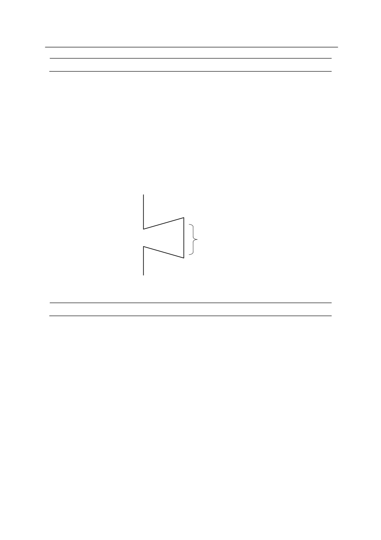
When this switch is ON and program execution is held during execution of a non-motion step, the
step in the currently executed stepper is displayed instead of the motion instruction just completed.
For example in the situation below, if the switch is ON, the stepper step of SWAIT is displayed
(SWAIT can be skipped). If the switch is OFF, the motion step A is displayed.
Motion step A
×
(completed)
×
Subroutine without a motion instruction
×
SWAIT䊹Stepper
×
×
Default setting is OFF.
㻌
WS_COMPOFF
㻻㼜㼠㼕㼛㼚㻌
Function㻌
Changes the output condition of the welding signal (WS).
Explanation㻌
When this switch is ON, WS signal is output from the moment memory change occurs until
the welding complete signal is input.
When this switch is OFF, WS signal is output from the moment memory change occurs until
the next memory change.
Default setting is OFF.
7-19
7. System Switches
㻌
FLOWRATE
㻻㼜㼠㼕㼛㼚㻌
Function㻌
Switches between flow rate control mode and speed output mode.
Explanation㻌
When this switch is ON, the flow rate control mode is selected.
When this switch is OFF, the speed output mode is selected.
Default setting is OFF.
㻌
㻌
㻌
㻌
㻌
㻌
㻌
WS.ZERO
Option
Function㻌
Changes the operation done when the WS signal is 0.
Explanation㻌
When this switch is ON, the welding is done when WS=0, as well as when WS0.
(Pressurizing and welding)
When this switch is OFF, welding is not done when WS=0. (Pressurizing only)
Default setting is OFF.
7-20
7. System Switches
㻌
ABS.SPEED
㻌
Function㻌
Enables or disables the use of absolute speed. This function enables execution of motion
steps at a low, pre-defined speed setting, taking precedence over the monitor speed setting.
Explanation㻌
When this switch is ON, the robot moves at the absolute speed specified for the program
when the below condition is true.
Maximum speed Monitor Speed > Program Speed
Also, when this switch is ON, the acceleration speed stays at the speed equivalent to monitor
speed 100%, independent from the change in monitor speed.
Example㻌
If Max speed 2400 mm/s, Monitor Speed 10 %, Program Speed 100 mm/s, then
2400 0.1 > 100
The robot moves at the program speed 100 mm/s.
If Max speed 100 %, Monitor Speed 10 %, Program Speed 5 %, then
100 0.1 >5
The robot moves at the program speed 5 %.
If Max speed 2400 mm/s, Monitor Speed 2 %, Program Speed 100 mm/s, then
2400 0.02 < 100
The robot moves at the monitor speed 48 mm/s.
7-21
7. System Switches
㻌
SLOW_START
㻌
Function㻌
Enables (ON) or disables (OFF) the slow start function. If the slow start function is enabled,
the robot starts motion at slow repeat speed in the first motion step or during a specified time
at the beginning of the motion.
Explanation㻌
When this switch is turned ON, the slow start function is enabled in repeat mode or in fast
check mode (option).
Set the speed in slow repeat mode using SLOW_REPEAT command or Aux. 0508 Slow
Repeat.
Also, in Aux. 0508, the time to operate in slow speed can be set (slow speed repeat time at
startup). When slow speed repeat time at startup is set as 0, only the first motion step is
executed in slow speed.
If a program is stopped and then restarted, the first motion step to be executed will start at the
slow repeat speed.
AFTER.WAIT.TIMR
㻌
Function㻌
Sets the timing for starting timers in block instructions.
Explanation㻌
When this switch is OFF, the timer starts when the axes coincide. If it is ON, the timer starts
when the axes coincide and all the set conditions (e.g. WX, WAIT, RPS ON) are fulfilled.
Default setting is OFF.
7-22
7. System Switches
SF_OPEN_ERROR
㻌
Function㻌
Determines if error is given or not when the safety fence is open in repeat mode. If this
switch is ON, error “(E1326) Safety fence is open.” Occurs when the safety fence is open in
repeat mode.
Explanation㻌
This switch is used to determine whether error “(E1326) Safety fence is open.” is given or not
when the safety fence is open in repeat mode.
When this switch is ON, “(E1326) Safety fence is open.” is given and the robot control
program stops.
When this switch is OFF, error is not given. The robot control program does not stop, but the
error “(E1326) Safety fence is open.” Is displayed in the system area of the teach pendant.
Default setting is ON.
Example㻌
SF_OPEN_ERROR ON
Error “(E1326) Safety fence is open.” When the safety fence is
open in repeat mode.
7-23
7. System Switches
STAT_ON_KYBD
㻌
Function㻌
Sets if the status information is displayed on the keyboard screen or not.
Explanation㻌
When this switch is OFF, the status information is not displayed and the keyboard screen is
displayed at full-screen. If it is ON, the status information is displayed on the top part of the
keyboard screen, as in the teach screen. The keyboard screen will be smaller by 4 lines than
the full-screen display.
Default setting is ON.
㻌
WAITREL_AUTO
㻌
Function㻌
Sets if the wait release popup window is displayed or not when the robot comes to a wait in
teach or check mode.
Explanation㻌
When this switch is ON, the popup window appears when the robot is in wait status. If it is
OFF, the popup window is not displayed.
Default setting is ON.
7-24
7. System Switches
REP_ONCE.RPS_LAST
㻌
Function㻌
Sets on which step to end the program execution when the program is repeated once via RPS
function.
Explanation㻌
When this switch is ON with REP_ONCE switch ON (repeat once) the program is repeated
once and then ends execution with the program that the END step is taught, without moving
on to the next program.
If it is OFF, the program moves on to the next program after executing the END step and
stops at the first step of that program.
Default setting is OFF.
7-25
7. System Switches
DEST_CIRINT
㻌
Function㻌
Determines the pose where the DEST/#DEST function returns on the circular trajectory
within the accuracy circle in Motion type 2.
Explanation㻌
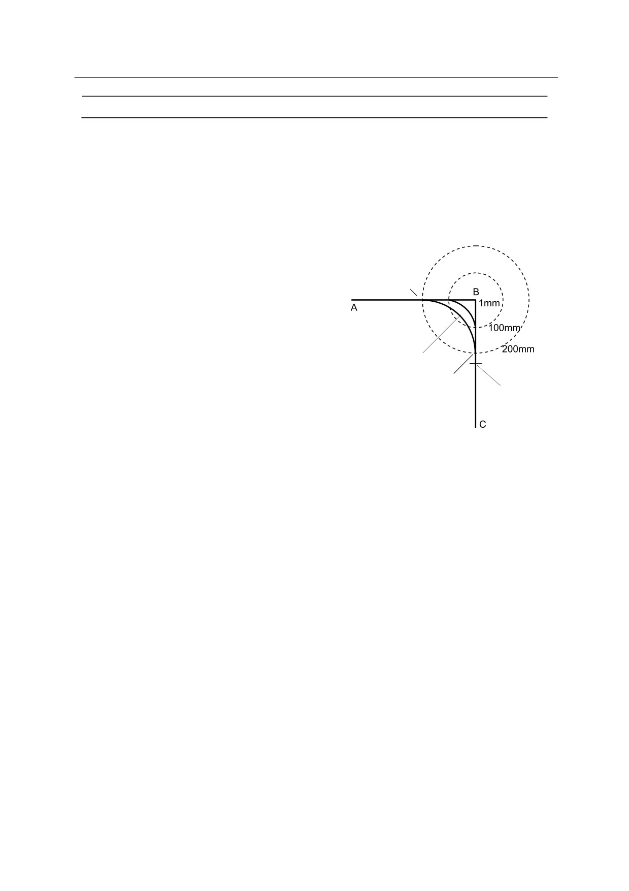
The robot’s motion trajectory when moving in
Linear
linear interpolation motion along A→B→C in
Interpolated
motion type 2 will be as shown in the figure below.
motion
㻭’
This figure shows the example when the accuracy
setting at point B is 1 mm, 100 mm, 200 mm. The
robot starts to shortcut to the next path when as
soon as it enters the accuracy circle of the set
Circular arc
accuracy. The robot will follow a circular
㻮’㻌
Maximum shortcut:
trajectory within the accuracy circle. See also
half the distance of
“4.5.4 Relation between CP Switch and
next path
ACCURACY, ACCEL, DECEL”.
When DEST/#DEST functions are used in the following two timing, the returned pose can be
changed by setting this switch ON or OFF.
1. When the robot is between point A and the point starting circular motion
2. When the robot is following the circular trajectory (within the accuracy circle)
When this switch is ON, at accuracy setting of 200 mm, point A’ is returned at timing 1, and
point B’ is returned for timing 2.
When this switch is OFF, at accuracy setting of 200 mm, point B is returned at timing 1, and
point C is returned for timing 2.
Default setting is ON.
7-26

7. System Switches
PROG.DATE
㻌 㻌 㻌 㻌 㻌 㻌 㻌 㻌 㻌 㻌 㻌 㻌 㻌 㻌 㻌 㻌 㻌 㻌 㻌 㻌 㻌 㻌 㻌 㻌 㻌 㻌 㻌 㻌 㻌 㻌 㻌 㻌 㻌 㻌 㻌 㻌 㻌 㻌 㻌 㻌 㻌 㻌 㻌 㻌 㻌 㻌 㻌 㻌 㻌 㻌 㻌 㻌 㻌 㻌 㻌 㻌 㻌 㻌 㻌 㻌 㻌
Function㻌
Determines if the date of program modification is added to the program information or not.
Explanation㻌
When this switch is ON, an item selection button is displayed in the program list screen.
Pressing this button will display the total number of execution times and the program
modification date.
When this switch is OFF, the item selection button is not displayed on the program list screen.
The number of steps in the program and its comment are displayed instead of the program list.
Default setting is OFF.
INSERT_NO_CONFIRM
㻌 㻌 㻌 㻌 㻌 㻌 㻌 㻌 㻌 㻌 㻌 㻌 㻌 㻌 㻌 㻌 㻌 㻌 㻌 㻌 㻌 㻌 㻌 㻌 㻌 㻌 㻌 㻌 㻌 㻌 㻌 㻌 㻌 㻌 㻌 㻌 㻌 㻌 㻌 㻌 㻌 㻌 㻌 㻌 㻌 㻌 㻌 㻌 㻌 㻌 㻌 㻌 㻌 㻌 㻌 㻌 㻌 㻌 㻌 㻌 㻌
Function㻌
Selects whether confirmation message is displayed or not when insertion operation is done in
teach operation.
㻌
Explanation㻌
When this switch is ON, the confirmation message is not displayed when insertion operation
is done in teach operation.
When this switch is OFF, the confirmation message is displayed when insertion operation is
done in teach operation.
㻌
Default setting is OFF.
㻌
7-27
7. System Switches
SIGMON_TEACH
㻌 㻌 㻌 㻌 㻌 㻌 㻌 㻌 㻌 㻌 㻌 㻌 㻌 㻌 㻌 㻌 㻌 㻌 㻌 㻌 㻌 㻌 㻌 㻌 㻌 㻌 㻌 㻌 㻌 㻌 㻌 㻌 㻌 㻌 㻌 㻌 㻌 㻌 㻌 㻌 㻌 㻌 㻌 㻌 㻌 㻌 㻌 㻌 㻌 㻌 㻌 㻌 㻌 㻌 㻌 㻌 㻌 㻌 㻌 㻌 㻌
Function㻌
Selects whether operation of hard key in O signal. I/O name and KLogic monitor is nullify or
not in teach repeat or teach lock disabled.㻌 㻌
㻌
Explanation㻌
㻌
When this switch is ON, signal operation from monitor screen is not allowed when repeat
mode is enabled or teach lock is disabled. Operation can be done only when in teach/ check
mode or when teach lock is valid.
When this switch is OFF, the robot can be operated both in repeat mode and teach mode.
Default setting is OFF.
㻌
TOUCH.ENA
㻌 㻌 㻌 㻌 㻌 㻌 㻌 㻌 㻌 㻌 㻌 㻌 㻌 㻌 㻌 㻌 㻌 㻌 㻌 㻌 㻌 㻌 㻌 㻌 㻌 㻌 㻌 㻌 㻌 㻌 㻌 㻌 㻌 㻌 㻌 㻌 㻌 㻌 㻌 㻌 㻌 㻌 㻌 㻌 㻌 㻌 㻌 㻌 㻌 㻌 㻌 㻌 㻌 㻌 㻌 㻌 㻌 㻌 㻌 㻌 㻌
Function㻌
Selects whether touch panel operation of the repeat conditions are enabled or disabled.
When set to disable, avoids mistaken operation of the touch panel when the touch panel is
touched accidently.
㻌
Explanation㻌
When this switch is ON, all the items of repeat conditions can be operated from the touch
panel.
When this switch is OFF, touch panel operation is disable except for “speed specification”,
“䕦+10%”, “䕦-10%”. However operation using the cursor keys are possible.
Default setting is ON.
7-28