Kawasaki Robot Controller E Series. Reference Manual (2015) - page 11
6. Program Instructions
Explanation
IFPWPRINT command can be used only when the interface panel is available for use. If the
parameters are not specified, the last setting of that particular window is selected (for first time
use, the above default values are set). If the character string does not fit in one row, its display
overflows to the next line (indenting to the selected column). Strings that extend beyond the
size of the window are not displayed. Control characters in the string are displayed as blanks.
6-99
6. Program Instructions
IFPWOVERWRITE window number, row, column, background color,
label color = “character string”, “character string”, ……
Function
Displays by overwriting the specified character string in the string window set by Auxiliary
Function 0509 (Interface panel screen).
Parameter
Window number
Corresponds to the window number specified in Auxiliary Function 0509 as the window
specification used to display the string. Select from 1to 8 (standard).
Row
Specifies the row in the window for displaying the string. Acceptable number is from 1 to 4,
though it depends on the window size. If not specified, 1 is assumed.
Column
Specifies the column in the window for displaying the string. Acceptable number is from
1 to 78, though it depends on the window size. If not specified, 1 is assumed.
Background color
Selects the color of the background of the selected window. Acceptable numbers are from
0 to 15. If not specified, the background is white.
No.
Color
No.
Color
No.
Color
No.
Color
0
Grey
4
Green
8
Pink
12
Navy
1
Blue
5
Pale Blue
9
White
13
Reddish Brown
2
Red
6
Yellow
10
Black
14
Deep Green
3
Orange
7
White
11
Cyan
15
Lavender
Label color
Selects the color of the characters displayed. Acceptable numbers are from 0 to 15
(See chart
above). If not specified, the characters are displayed in black.
Character string
Specifies the character string to display. All strings after the first string are displayed on the next
row starting at specified column.
6-100
6. Program Instructions
Explanation
IFPWOVERWRITE command can be used only when the interface panel is available for use. If
the parameters are not specified, the last setting of that particular window is selected (for first
time use, the above default values are set). If the character string does not fit in one row, its
display overflows to the next line (indenting to the selected column). Strings that extend beyond
the size of the window are not displayed. Control characters in the string are displayed as blanks.
Unlike IFPWPRINT command/ instruction, the rows other than the row specified for display are
displayed unchanged as before executing IFPWOVERWRITE.
Example
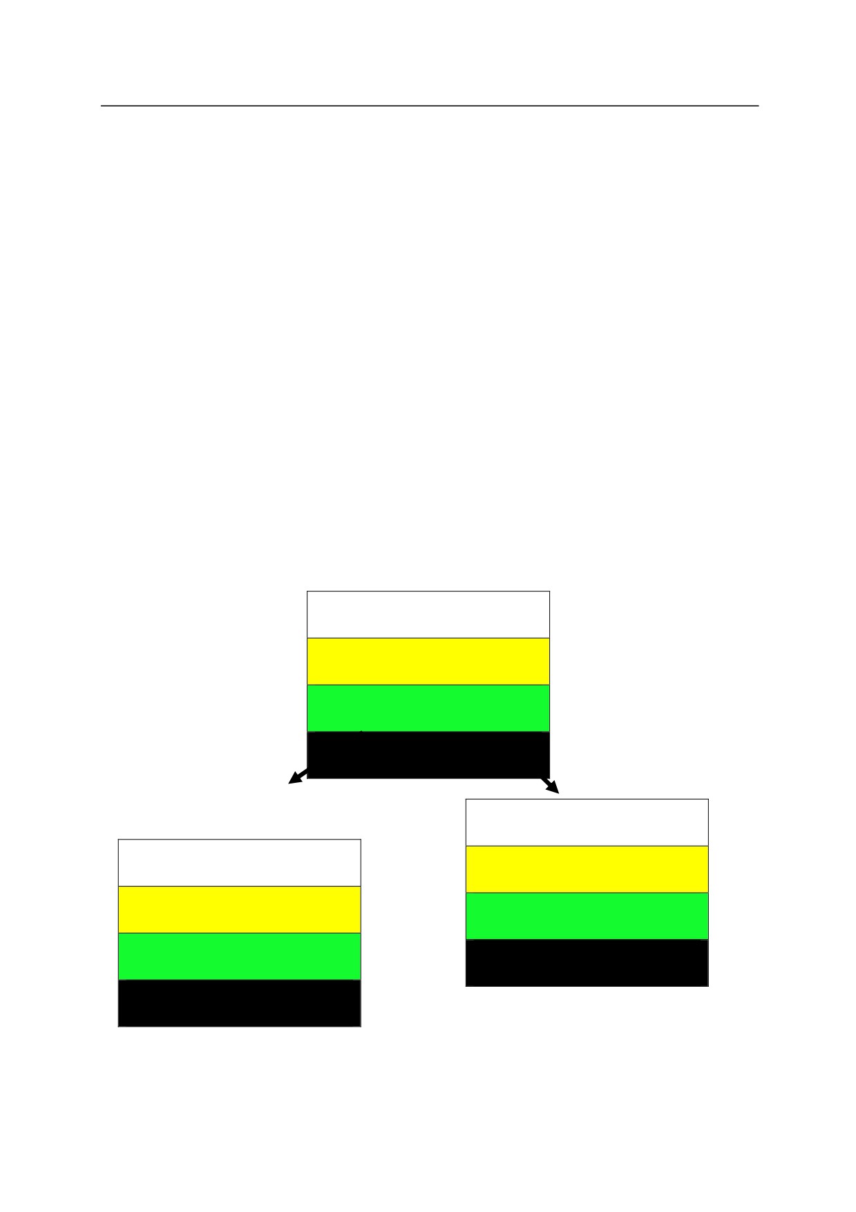
The figures below show the screens displayed when executing IFPWPRINT and
IFPWOVERWRITE command/ instruction from the screen showing “This is a pen”. The left
figure is the figure after executing ”IFPWPRINT 1,3,1,7,10=”my”. The characters on lines 1, 2,
and 4 disappear and line 3 shows ”my”. On the other hand, the right figure shows the screen
after executing “IFPWOVERWRITE 1,3,1,7,10=”my”. The characters on lines 1, 2, and 4 are
displayed as they wer
e before executing the instruction and only line 3 has changed to ”my”.
This
is
a
pen
Displays
“This is a pen”
This
is
my
pen
my
Screen after executing
Screen after executing
IFPWPRINT 1,3,1,7,10 =“my”
IFPWOVERWRITE 1,3,1,7,10 =“my”
6-101
6. Program Instructions
IFPLABEL position, "label 1", "label 2", "label 3", "label 4"
Function
Sets and modifies the label of the icon at the specified position on the interface panel.
Parameter
Position
Specifies the display position on the interface panel of the icon to set/ modify the label.
Setting range: 1 - 112.
Displays
“This is a pen”
“Label 1”, “Label 2”…
Specifies the character string to display on the interface panel as the label of the specified icon.
Omitted label will not be changed.
Explanation
Sets and modifies the label for the icons displayed on the interface panel. When a position with
no icon set or when an icon with no label is specified, nothing occurs.
See also 5.8 IFPLABEL monitor command.
Screen after executing
Screen after executing
IFPWPRINT 1,3,1,7,10 =“my”
IFPWOVERWRITE 1,3,1,7,10 =“my”
6-102
6. Program Instructions
IFPTITLE page no., "title"
Function
Sets and modifies the title for the specified page of the interface panel.
Parameter
Page no.
Specifies the page of the interface panel to change the title. Setting range: 1- 4.
“Title”
Specifies the character string to display on the page as the title. Default setting is “Interface
Panel”. When NULL string (“”) is specified, this default setting is also displayed.
Explanation
Sets and modifies the title for the specified page of the interface panel.
See also 5.8 IFPTITLE monitor command.
6-103
6. Program Instructions
SETOUTDA port No. = LSB, No. of bits, logic, max. voltage, min. voltage
Option
Function
Specifies the analog output environment including: port number and LSB, number of bits and
logic voltage for signal output, maximum and minimum voltage.
Parameter
Port No.
Specifies port number. Setting range: integer between 1 and 10.
LSB
Specifies as an integer the first signal number to be output for D/A conversion. Setting range:
OUT 1 - OUT 125, 2001 - 2125, 3000 (1st channel of 1TW), 3001 (2nd channel of 1TW/ 1 UR).
Default value is 3000. Previous setting remains in effect if not specified.
Number of bits
Specifies the integer number of bits output for each signal to be D/A converted. Setting range: 4
bits - 16 bits. Set to 12 bits when specifying 3000 - [3000 + number of DA channel on 1TW/ 1
UR board] for parameter LSB above. Default value is 8 bits. Previous setting remains in
effect if not specified.
Logic
Sets output data either to positive logic (1) or negative logic (0). Initial set value is 0 (negative
logic). Previous setting remains in effect if not specified. Set the logic to positive for 1TW/ 1
UR.
Maximum voltage
Specifies the maximum voltage of hardware (D/A output). Setting range: -15 - +15V. Unit: V.
Initial set value is 13V. Round off to first decimal place. Previous setting remains in effect if
not specified.
Minimum voltage
Specifies the minimum voltage of hardware (D/A output). Setting range: -15 - +15V. Unit: V.
Initial set value is 0V. Round off to first decimal place. Previous setting remains in effect if
not specified.
[ NOTE ]
1. Actual voltage output depends on the hardware used.
2. An error will occur if the value for maximum voltage is set lower than the minimum
voltage.
6-104

6. Program Instructions
OUTDA voltage, port no.
Option
Function
Outputs voltage according to the conditions set to the specified port number.
Parameter
Voltage
Specifies the voltage to be output from D/A port. Setting range: -15 - +15 V. Unit: 0.1 V.
Round off to first decimal place.
Port No.
Specifies port number. Setting range: integers between 1-16. If not specified, 1 is assumed.
[NOTE]
Confirm that command voltage and actual output voltage are the same by setting
output environment to correspond with the hardware settings via SETOUTDA
instruction (command).
6-105
6. Program Instructions
6.9 POSE INFORMATION INSTRUCTIONS
HERE
Assigns the current pose to the specified variable.
POINT
Defines a pose variable.
POINT/X
Sets the X value of a transformation value variable.
POINT/Y
Sets the Y value of a transformation value variable.
POINT/Z
Sets the Z value of a transformation value variable.
POINT/OAT
Sets the OAT values of a transformation value variable.
POINT/O
Sets the O value of a transformation value variable.
POINT/A
Sets the A value of a transformation value variable.
POINT/T
Sets the T value of a transformation value variable.
POINT/7
Sets the value of seventh axis of a transformation value variable.
POINT/18
Sets the value of 18th axis of a transformation value variable.
Sets the value of external axes (7 䇵 18th axes)of a transformation
POINT/EXT
value variable.
DECOMPOSE
Assigns the components of pose information to elements of array
variable.
BASE
Changes the robots base coordinate system.
TOOL
Defines the pose of TCP.
SET_TOOLSHAPE
Sets tool shape data.
ENA_TOOLSHAPE
Enables/ disables speed control by tool shape.
TOOLSHAPE
Sets data for speed control by tool shape.
SETHOME
Sets pose for HOME.
SET2HOME
Sets pose for HOME 2.
LLIMIT
Sets the upper limit of the robot motion.
ULIMIT
Sets the lower limit of the robot motion.
TIMER
Sets the timer.
UTIMER
Sets the timer value of user timer.
ON
Turns ON system switch.
OFF
Turns OFF system switch.
NCHON
Turns ON notch filter. (Option)
NCHOFF
Turns OFF notch filter. (Option)
WEIGHT
Sets the weight load data.
6-106
6. Program Instructions
MC
Executes monitor commands from PC programs.
TPLIGHT
Turns on teach pendant backlight.
CURLIM
Changes the motor current limit of the external axis.
SETTIME
Sets the time and date
ENVCHKRATE
Magnification ratio to the threshold value for external axis
d i i
6-107
6. Program Instructions
HERE pose variable
Function
Assigns the current pose to the specified variable. The pose may be expressed in transformation
values, joint displacement values or compound transformation values.
Parameter
Pose variable
Can be defined in transformation values, joint displacement values, or compound transformation
values.
[ NOTE ]
Only the right most variable in the compound transformation value is defined. If the
other variables used in the compound value are not defined, this command results in
an error.
㻌
See also 5.5 HERE monitor command.
6-108
6. Program Instructions
POINT pose variable 1= pose variable 2, joint displacement value variable
Function
Assigns the values of pose variable 2 to pose variable 1.
Parameter
Pose variable 1
Specifies the name of pose variable to be defined (by joint displacement values, transformation
values, or compound transformation values). In the case of compound transformation values,
POINT specifies the rightmost variable value.
Pose variable 2
Specify the name of variable defined by joint displacement values or transformation values.
Joint displacement value variable
This parameter must be set if the values of pose variable 1 are in joint displacement values and
the values of pose variable 2 are in transformation values (if pose variable 1 is not defined by
joint displacement values, this parameter cannot be set). The joint displacement values specified
here expresses the configuration of the robot at the pose. If not specified, the current
configuration is used to define the pose variable.
Explanation
An error is returned if pose variable 2 is not defined.
When pose variable 1 is defined in compound transformation values, the right most variable is
defined. If the other variables used in the compound variables are not defined, this command
will result in an error.
See also 5.5 POINT monitor command.
6-109
6. Program Instructions
POINT/ X transformation value variable 1 = transformation value variable 2
POINT/ Y transformation value variable 1 = transformation value variable 2
POINT/ Z transformation value variable 1 = transformation value variable 2
POINT/ OAT transformation value variable 1 = transformation value variable 2
POINT/ O transformation value variable 1 = transformation value variable 2
POINT/ A transformation value variable 1 = transformation value variable 2
POINT/ T transformation value variable 1 = transformation value variable 2
POINT/ 7 transformation value variable 1 = transformation value variable 2
䞉
䞉
䞉
POINT/18 transformation value variable 1 = transformation value variable 2
POINT/EXT transformation value variable 1 = transformation value variable 2
Function
Assigns the specified component(s) of transformation value variable 2 to the corresponding
component(s) of transformation value variable 1. The values will be displayed on the terminal
for correction.
Parameter
Transformation value variable 1
Specifies a single transformation value variable, or a variable defined by compound
transformation values with the last component defined in transformation values.
Transformation value variable 2
Specifies the name of a variable defined by transformation value, compound transformation value
or transformation value function. 㻌 The name of this variable must be defined beforehand.
Explanation
Error occurs if any pose variable on the right side of the “=” is not defined.
If compound transformation value variables are specified for transformation value variable 1, this
instruction assigns values to only the rightmost variable. Also, error occurs if any variable other
than the rightmost variable is undefined.
Example
POINT/X temp=tempx㻌 㻌 Assigns the x component of transformation value variable “tempx”
to the x component of transformation value variable “temp”.
POINT/EXT temp=tempx Assigns the external axes components of transformation value
variable tempx to the external axes components of transformation
value variable temp.
6-110
6. Program Instructions
DECOMPOSE array variable [element number] = pose variable
Function
Stores as elements of an array variable, each component of the values of the specified pose
variable (X, Y, Z, O, A, T for transformation values; JT1, JT2, JT3, JT4, JT5, JT6 for joint
displacement values).
Parameter
Array variable
Specifies the name of the array variable into which the values of each component will be
assigned.
Element number
Specifies the first element in which to store the components.
Pose variable
Specifies the name of the pose variable from which to extract each component (transformation
values, joint displacement values).
Explanation
This assigns the components of the specified pose information to the elements of the array
variable.
In case of transformation values, six elements are assigned from each of the XYZOAT values.
In case of joint displacement values, the elements are each assigned from the values of each joint
in the robot arm.
Example
DECOMPOSE X[0]=part
Assigns the components of transformation value variable “part”
to the first six elements in the array variable “x”.
DECOMPOSE angles[4]=#pick Assigns the components of joint displacement value variable
“#pick” to array variable “angles”, starting from element
number 4.
For example, in the above instruction, if the values of #pick are (10,20,30,40,50,60) then,
angles[4]=10
angles[7]=40
angles[5]=20
angles[8]=50
angles[6]=30
angles[9]=60
6-111
6. Program Instructions
BASE transformation value variable
Function
Defines the base transformation values.
Parameter
Transformation value variable
Specifies a transformation value variable or compound transformation value variables. Defines
the new base coordinates. The pose variable here describes the pose of the base coordinates
with respect to the null base coordinates, expressed in null base coordinates.
Explanation
The CP movement is stopped (BREAK) and the base transformation values are changed to the
specified transformation values when this instruction is executed.
See also 5.6 BASE monitor command.
6-112
6. Program Instructions
TOOL transformation value variable, tool shape number
Function
Defines the transformation values that shows the pose of the tool tip (tool transformation values)
as seen from the tool mounting flange surface (null tool coordinates).
Parameter
Transformation value variable
Specifies a transformation value variable or compound transformation value variable to define the
new tool coordinates. The transformation value variable here describes the pose of the tool
coordinates with respect to the null tool coordinates, expressed in null tool coordinates. If
“NULL” is specified for the parameter, the tool coordinates will be set same as the null tool
coordinates.
Tool shape number
Specifies the tool shape to use for speed control in teach and check mode. This may be omitted.
If not specified, speed control by tool shape will not be done.
Explanation
The continuous path (CP) movement is stopped (BREAK) and the tool transformation values are
changed to the specified transformation values when this instruction is executed.
See also 5.6 TOOL monitor command.
6-113
6. Program Instructions
SET_TOOLSHAPE 㻌 tool shape no. = transformation value variable 1,㻌
transformation value variable 2,㻌 …,㻌 transformation value variable 8
Function
Registers the tool shape used to control speed in teach mode and check mode.
Parameter
Tool shape no.
Specifies the number of tool shape to register. Setting range: 1 to 9.
Transformation value variables 1-8
Specifies transformation value variables for the points on the tool shape. Maximum of 8 points
can be specified. The points are specified in transformation values as seen from the center of the
flange surface. However, only the X,Y, Z values of the transformation values are used for the
tool shape registration.
Explanation
Defines the tool shape used for speed control in teach and check modes by maximum 8 points
specified in pose variables defined by transformation values.
See also 5.6 SET_TOOLSHAPE command.
6-114
6. Program Instructions
ENA_TOOLSHAPE tool shape no. = TRUE/ FALSE
Function
Enables/ disables speed control in teach and check mode.
Parameter
Tool shape number
Specifies the number of the tool shape to set enable/ disable.
TRUE/FALSE
Specify TRUE to enable speed control by the specified tool shape. Specify FALSE to disable
the speed control.
Explanation
Selects if speed control in teach and check modes are done by the specified tool shape or not.
FALSE is selected for all tool shapes as default setting. If TRUE is selected for a tool shape
number with not even one point specified, error E1356 Tool shape not set occurs when the robot
is operated in teach or check mode. To avoid this, always set at least one tool point via
SET_TOOLSHAPE command or change from TRUE to FALSE via this command an d then
execute TOOL or TOOLSHAPE command specifying the relevant tool shape number. (Once set
to TRUE, the setting will not be changed to FALSE unless TOOL/TOOLSHAPE command is
executed.)
TOOLSHAPE tool shape no.
Function
Selects the tool shape used to control speed in teach mode and check mode.
Parameter
Tool shape no.
Specifies the number of the tool shape used for speed control. Setting range: 1 to 9.
Explanation
To enable speed control in teach mode and check mode, the function must be enabled by
ENA_TOOLSHAPE command/ instruction (ENA_TOOLSHAPE n =TRUE). Error E1356 Tool
shape not set occurs if a tool shape with no point registered (all points set to 0) is selected.
See also 5.6 TOOLSHAPE command.
6-115
6. Program Instructions
SETHOME accuracy, joint displacement value variable
SET2HOME accuracy, joint displacement value variable
Function
Sets HOME pose.
Parameter
Accuracy
Sets the accuracy range of the HOME pose in millimeters.
Joint displacement value variable
Specifies a joint displacement value variable to set the pose for HOME.
Explanation
Sets robot’s HOME pose by specifying its joint displacement values (in units of degrees).
See also 5.6 SETHOME/ SET2HOME command.
Example
SETHOME 10, #place
Records the pose determined by joint displacement value variable
#place as HOME. The accuracy is set to the range of within 10 mm
of HOME.
6-116
6. Program Instructions
ULIMIT joint displacement value variable
LLIMIT joint displacement value variable
Function
Sets and displays the upper/lower limit of the robot motion range.
Parameter
Joint displacement value variable
Specifies a joint displacement value variable for software limit (upper or lower).
Explanation
Sets the upper (lower) limit of the robot motion range in joint displacement values (in degrees).
See also 5.6 ULIMIT/LLIMIT monitor commands
TIMER timer number 䠙 time
Function
Sets the time of the specified timer.
Parameter
Timer number
Specifies the number of the timer to set the time. Acceptable numbers are 1 to 10.
Time
Specifies the time to set to the timer in seconds.
Explanation
When this instruction is executed, the timer is immediately set to the specified time. Check the
value of the timer using TIMER function.
Example
The example below holds the program execution for the specified time using the TIMER
instruction and TIMER function.
TIMER
1=0
Sets Timer 1 to 0 (seconds)
WAIT TIMER(1)>delay
Waits until the value of Timer 1 is greater than
delay.
6-117

6. Program Instructions
UTIMER
@timer variable = timer value
Function
Sets the default value for the user timer. The user timer can be named freely using the timer
variable. More than one user timer can be used at a time.
Parameter
@Timer variable
Specified the variable or array variable name to use as the timer name. Enter @ in front of a
whole number variable.
Timer value
Specifies the default value for the timer. Acceptable numbers are 0 to 2147483647 (seconds).
switch name, ……ON
switch name, ……OFF
Function
Turns ON (OFF) the specified system switch.
Parameter
Switch name
Turns ON (OFF) the switch specified here. More than one switch name can be entered
separating each switch name by commas.
The current setting of the switch can be checked using the SWITCH command.
See also 5.6 ON/OFF monitor commands.
6-118
6. Program Instructions
NCHON
NCHOFF
Option
Function
Turns ON (or OFF) the notch filter in the motion steps following the specified step. NCHON
enables the notch filter, NCHOFF disables it.
Example
10
SPEED
100 ALWAYS
20
HOME
30
DRIVE5,90
40
NCHOFF
50
SPEED
10
This linear movement is done with the notch filter OFF.
60
DRAW 1000
70
NCHON
80
DRAW,-500
[ NOTE ]
Normally use with NCHON.
NCHOFF is used when small vibration can be seen in low speed operations, or when an
external force is being applied to the robot.
The filter is reset with the execution of EXECUTE command. It is also reset when
PRIME, STEP, MSTEP commands are first executed. The default setting is ON (notch
filter enabled).
6-119
6. Program Instructions
WEIGHT load mass䠈center of gravity X, center of gravity Y,
center of gravity Z, inertia moment ab. X axis,
inertia moment ab. Y axis, inertia moment ab. Z axis
Function
Sets the load mass data (weight of the tool and workpiece). The data is used to determine the
optimal acceleration/deceleration of the robot arm.
Parameter
Load mass
The mass of the tool and workpiece (in kilograms). Range: 0.0 to the maximum load capacity
(kg).
Center of gravity (unit = mm)
X: the x value of the center of gravity in tool coordinates
Y: the y value of the center of gravity in tool coordinates
Z: the z value of the center of gravity in tool coordinates
Inertia moment about X axis, inertia moment about Y axis, inertia moment about Z axis
(Option)
Sets the inertia moment around each axis. Unit is kg·m2. The inertia moment about each axis
is defined as the moment around the coordinates axes parallel to the null tool coordinates with the
center of rotation at the tool’s center of gravity.
Explanation
If the parameters are not specified when using WEIGHT as a program instruction, the setting
defaults to the maximum load capacity for that robot model.
!
DANGER
Always set the correct load mass and center of gravity. Incorrect data may
weaken or shorten the longevity of parts or cause overload / deviation errors.
6-120
6. Program Instructions
MC monitor command
Function
Enables execution of monitor commands from PC programs. Monitor commands that can be
used with this instruction are: ABORT, CONTINUE, ERESET, EXECUTE, HOLD, and SPEED.
Explanation
This instruction is used in cases when a robot program is executed (EXECUTE command) from
program AUTOSTART.PC. MC instruction cannot be used in robot programs.
Example
Robot programs can be executed from AUTOSTART.PC using this command. However, the
motor power has to be ON to execute robot programs, so when using MC instruction, add the
following steps to check if the power is ON.
autostart.pc()
1 10 IF SWITCH(POWER)==FALSE GO TO 10
2 MC EXECUTE pg1
.END
TPLIGHT
Function
Turns on the teach pendant backlight.
Explanation
If the backlight of the teach pendant screen is OFF, this instruction turns ON the light. If this
instruction is executed when the backlight is ON, the light stays ON for the next 600 seconds.
6-121
6. Program Instructions
CURLIM axis number,㻌 positive current limit, negative current limit
㻌
Function
Changes the motor current limit of the external axis.
Parameter
Axis number
Specifies the number of the external axis. Acceptable range: 7-18.
Positive current limit
Specifies the positive limit of the motor current. The limit is set as percentage of current limit
set in the external axis servo parameter. Unit: %. Acceptable range: greater than 0 and less
than equal to 100.
Negative current limit
Specifies the negative limit of the motor current. The limit is set as percentage of current limit
set in the external axis servo parameter. Unit: %. Acceptable range: greater than 0 and less
than equal to 100.
Explanation
This instruction is valid only for external axis with KHI amplifier.
The changed limits are reflected on the current limit values of external axis servo parameters at
the following timing:
䞉 When program is executed via EXECUTE command
䞉 When a new program is reselected and executed via cycle start.
䞉 When program execution is reset.
䞉 When controller power is turned OFF/ON.
6-122
6. Program Instructions
㻌
SETTIME year, month, day, hour, minute, second
㻌
Function
Sets the current time and date.
Parameter
year, month, day, hour, minute, second
Sets the time and date as shown below. Both the date and the time have to be entered as the
parameter even when changing only the time. The parameter values must be real values or real
variables.
Explanation
Specifying the time and date via this instruction changes the internal calendar of the robot.
Each element for setting the calendar is as below:
Year
(00 - 99) The last two digits of the year
Month
(01 - 12)
Day
(01 - 31)
Hour
(0 - 23)
Minute
(0 - 59)
Second
(0 - 59)
Example
SETTIME
14, 10, 29, 9, 45, 46
Sets the current time to October 29, 2014 9:45:46
6-123
6. Program Instructions
㻌
ENVCHKRATE axis number, coefficient
㻌
Function
Specifies the magnification ratio to the initial value of the threshold for detection of deviation
abnormality in the external axis.
Parameter
Axis number
Specifies the number of the external axis. Acceptable range: 7-18.
Coefficient
Specifies the desired magnification ratio to the initial value of the deviation abnormality detection
threshold. Acceptable range: 0 - 9.999. The default value is 1.0. The deviation abnormality
detection threshold is in its initial value when the magnification is set to the default. Specifying 0
nullifies the deviation abnormality check.
!
CAUTION
When the coefficient is set to greater than 1.0, the deviation error detection may
be delayed. If set to 0, deviation error check is invalidated. Be careful with the
motion of the set axis when setting the coefficient larger than 1.0 or to 0.
Explanation
This instruction is valid only for external axis with KHI amplifier. Also, this instruction is
executed only in repeat mode. This instruction is not executed in check mode.
The changed limits return to their initial values at the following timings:
䞉 When program is executed via EXECUTE command
䞉 When a new program is reselected and executed via cycle start.
䞉 When program execution is reset.
䞉 When the control power is turned OFF then ON.
䞉 When switched to teach mode.
6-124
6. Program Instructions
6.10 PROGRAM AND DATA CONTROL INSTRUCTIONS㻌
DELETE
Deletes programs and variables in robot memory.
DELETE/P
Deletes programs in robot memory.
DELETE/L
Deletes pose variables in robot memory.
DELETE/R
Deletes real variables in robot memory.
DELETE/S
Deletes string variables in robot memory.
DELETE/INT
Deletes integer variables in robot memory.
TRACE
Turns ON/OFF the TRACE function.
NLOAD
Reads specified file onto robot memory.
SLOAD
Reads specified file onto robot memory. File is specified in character
string.
6-125
6. Program Instructions
DELETE program name,
DELETE/P program name,
㻌
DELETE/L pose variable[array elements] ,
㻌
DELETE/R real variable [array elements] ,
㻌
DELETE/S string variable [array elements] ,
㻌
DELETE/INT string variable [array elements] ,
Function㻌
Deletes the specified data from the memory.
Parameters㻌
Program name (/P), pose variable (/L), real variable (/R), string variable (/S), integer variable
(/INT)
Specifies the type and name of the data to delete.
See also 5.2 DELETE monitor commands.
6-126
6. Program Instructions
㻌
TRACE stepper number䠖 ON/OFF
Function
Starts (ON) or ends (OFF) logging of robot or PC program to allow program tracing.
Parameters㻌
Stepper number
Specifies the program to log using the following number selection:
1: Robot program
1001: PC program 1
1004: PC program 4
1002: PC program 2
1005: PC program5
1003: PC program 3
If the program is not specified, the program currently in execution is logged.
ON/OFF
Starts/ ends logging.
Explanation㻌
If the necessary memory is not reserved using the SETTRACE command before TRACE ON, the
error (P2034) “Memory undefined” occurs. Execute SETTRACE before retrying.
See also 5.2 TRACE/SETTRACE monitor commands.
6-127
6. Program Instructions
NLOAD/IF/ARC device number = file name + file name + ···, status variable
Function
Reads the specified file from external memory device and loads it on to robot memory.
Parameter
Device number
Specifies where to display the current processing situation. Specify either 1 or 2:
1: Standard terminal (PC)
2: Teach pendant
When omitted, it is displayed where the program is executed.
File name
Specifies the file to load on to robot memory. When specifying more than one file, separate the
file names using +.
Status variable
Specifying 0 allows continuing program execution even when error occurs. The error code
is saved. When omitted, program execution stops at error occurrence.
Explanation
Loads on to robot memory the contents (program and variables) of the specified file.
Specifying a program with the same name as a program in the robot memory results in error,
and no new program is read.
1. Specifying NLOAD/IF loads interface panel data.
2. Specifying NLOAD/ARC loads arc welding data.
When there is a step that is not readable in a program being loaded, error message and
message “Step format incorrect. (0: Comment-out the step and continue reading, 1: Delete
program and terminate) appears. When continuing by selecting zero (0), modify the
program via editor after loading is completed.
[ NOTE ]
Pose variable, real variable, or a string variable with the same name as the
variable being read is over-written by the new data without any warning.
Example
NLOAD pallet
Reads the contents of file pallet.as on to the robot memory.
NLOAD f3.pg
Reads all the programs in file f3.pg on to the robot memory.
6-128