Kawasaki Robot Controller E Series. Reference Manual (2015) - page 10
6. Program Instructions
[ NOTE ]
ANY statement and its program instructions can be omitted.
ANY statement can be used only once in the structure. The statement must be at the
end of the structure as shown in the example below.
The colon “:” after the ANY statement can be omitted. When entering the colon,
always leave a space after ANY. Without a space, ANY: is taken as a label.
Both the ANY and END statements must be entered on their own line.
Example㻌
In the program below, if the value of real variable x is negative, the program execution stops after
the message is displayed. If the value is positive, the program is processed according to these 3
cases:
1. if the value is an even number between 0 and 10
2. if the value is an odd number between 1 and 9
3. if the value is a positive number other than the above.
IF x<0 GOTO 10
CASE x OF
VALUE 0,2,4,6,8,10:
PRINT "The number x is EVEN"
VALUE 1,3,5,7,9:
PRINT "The number x is ODD䇿
ANY :
PRINT "The number x is larger than 10"
END
STOP
10 PRINT "Stopping because of negative value"
STOP
6-69
6. Program Instructions
SCASE index variable OF
SVALUE string_1䠈……:
program instructions
SVALUE string_2䠈……:
program instructions
:
SVALUE string_n䠈……:
program instructions
ANY
:
program instructions
END
㻌 㻌 㻌 㻌 㻌 㻌 㻌 㻌 㻌 㻌 㻌 㻌 㻌 㻌 㻌 㻌 㻌 㻌 㻌 㻌 㻌 㻌 㻌 㻌 㻌 㻌 㻌 㻌 㻌 㻌 㻌 㻌 㻌 㻌 㻌 㻌 㻌 㻌 㻌 㻌 㻌 㻌 㻌 㻌 㻌 㻌 㻌 㻌 㻌 㻌 㻌 㻌 㻌 㻌 㻌 㻌 㻌 㻌 㻌 㻌 㻌 Option㻌
Function㻌
Executes program based on condition specified by the character string.
Parameter㻌
Index variable
Specifies character string variable or expression. Decides which SCASE structure to execute
according to character string of this variable.
Program instructions
Executes these program instructions when the string of the index variable equals one of the values
after the SVALUE statement.
Explanation㻌
Unlike CASE structure described before, the execution condition for SCASE structure is set as
character string. See also CASE structure.
If there is no string that matches the string character, the program instructions after the ANY
statement are executed. If there is not an ANY statement, none of the steps in the SCASE
structure is executed.
6-70
6. Program Instructions
[ NOTE ]
ANY statement and its program instructions can be omitted.
ANY statement can be used only once in the structure. The statement must be at the end
of the structure.
The colon “:” after the ANY statement can be omitted. When entering the colon, always
leave a space after ANY. Without a space, ANY: is taken as a label.
Both the ANY and END statements must be entered on their own line.
Example㻌
In the program below, if character string variable $str is equal to the string of $a+”c”, the program
pc is executed. If character string variable $str is equal to the string of $a+”g”, the program pg is
executed.
SCASE $str OF
SVALUE $a+”c”:
CALL pc
SVALUE $a+”g”:
CALL pg
END
6-71
6. Program Instructions
6.7 BINARY SIGNAL INSTRUCTIONS
RESET
Turns OFF all external output signals.
SIGNAL
Turns ON/OFF external I/O signals and internal signals.
PULSE
Turns ON output signal for the specified amount of time.
DLYSIG
Turns signal after the specified time has passed.
RUNMASK
Specifies the signals to mask.
BITS
Sets a group of signals to equal the specified value (Max. 16 signals )
BITS32
Sets a group of signals to equal the specified value (Max. 32 signals )
SWAIT
Suspends program execution until specified condition is set.
EXTCALL
Calls the program selected by external signal.
ON
Sets interruption condition.
ONI
Sets interruption condition.
IGNORE
Cancels ON or ONI instruction.
SCNT
Outputs counter signal at the specified counter value.
SCNTRESET
Clears the counter signal number.
SFLK
Turns ON/OFF the flicker signal in cycle of specified time.
SFLP
Turns ON/OFF signals with SET/RESET signals.
SOUT
Outputs signal when specified condition is set.
STIM
Turns ON timer signal when the specified signal is ON for specified
period of time.
SETPICK
Sets the time to start clamp close control. (Option)
SETPLACE
Sets the time to start clamp open control.
(Option)
CLAMP
Controls open/close of clamp signals. (Option)
HSENSESET
Starts monitoring of specified sensor signal. (Option)
HSENSE
Reads the data stored in buffer by HSENSESET. (Option)
6-72

6. Program Instructions
RESET
Function
Turns OFF all the external output signals. This command does not have effect on signals used
as dedicated signals, clamp signals and antinomy of multifunction OX/WX.
By using the optional setting, the signals used in the Interface Panel screen are not affected by this
command.
(Option)
SIGNAL signal number, ……
Function
Turns ON/OFF the specified external output signals (OX) or internal signals.
Parameter
Signal number
Selects the number of external output signal or internal signal. Selecting a dedicated signal
results in error.
Acceptable Signal Numbers
External output signal
1 㻌 actual number of signals
Internal signal
20012960
See also 5.7㻌 SIGNAL monitor command.
6-73

6. Program Instructions
PULSE signal number, time
Function
Turns ON the specified external output signal or internal signal for the given period of time.
Parameter
Signal number
Selects the number of external output signal or internal signal. Selecting a dedicated signal
results in error.
Acceptable Signal Numbers
External output signal
1 㻌 actual number of signals
Internal signal
20012960
Time
Sets for how long the signal is output (in seconds). If not specified, it is automatically set at 0.2
seconds.
See also 5.7㻌 PULSE monitor command
DLYSIG signal number, time
Function
Outputs the specified signal after the given time has passed.
Parameter
Signal number
Selects the number of the external output signal or internal signal. If the signal number is
positive, the signal is turned ON; if negative, the signal is turned OFF Selecting a dedicated signal
results in error.
Acceptable Signal Numbers
1 㻌 actual number of signals
External output signal
Internal signal
20012960
Time
Specifies the time to delay the output of the signal in seconds.
See also 5.7 DLYSIG monitor command.
6-74
6. Program Instructions
RUNMASK starting signal number, number of signals
Function
Allows signals to be ON only while the program is executing. The signals can be turned ON
using the SIGNAL, PULSE or DLYSIG command, but the signal turns OFF when the program
execution stops (if this instruction is not used, the signals remain ON once they are turned ON).
Parameter
Starting signal number
Specifies the number of the first external output signal or internal signal in the group of signals to
mask. Entering a negative number cancels the mask function for that signal number and the
signal does not become OFF when the program stops.
Acceptable Signal Numbers
External output signal
1 actual number of signals
Internal signal
20012960
Number of signals
Specifies how many signals are masked. If not specified 1 is assumed.
Explanation
The signals selected by this instruction always turns OFF when the program execution stops.
However, dedicated signals are not affected by this instruction.
If the program execution is interrupted, the masked signals turn OFF. When the program is
resumed using the CONTINUE command, the signals return to the status they were in when the
program was running. The same occurs with DO command or STEP command.
(Restarting
program via EXECUTE command nullifies the RUNMASK instruction.)
Example
RUNMASK
5,2
Masks the external output signal 5 and the next signal 6, specified by 2 bits.
While the program is running these signals can be turned ON by SIGNAL,
PULSE, or DLYSIG command. They are turned OFF when the program
execution stops.
6-75

6. Program Instructions
BITS starting signal number, number of signals = decimal value
Function
Arranges a group of external output signals or internal signals in a binary pattern. The signal
states are set ON/OFF according to the binary equivalent of the decimal value specified.
Parameter
Starting signal number
Specifies the first signal to set the signal state.
Acceptable Signal Numbers
External output signal
1 㻌 actual number of signals
Internal signal
20012960
Number of signals
Specifies the number of signals to be set ON/OFF. The maximum number allowed is 16. To
set more than 16 signals, use BITS32 instruction, explained next.
Decimal value
Specifies the decimal value used to set the desired ON/OFF signal states. The decimal value is
transformed into binary notation and each bit of the binary value sets the signal state starting from
the least significant bit. If the binary notation of this value has more bits than the number of
signals, only the state of the given number of signals (starting from the specified signal number)
is set and the remaining bits are ignored.
See also 5.7 BITS monitor command.
6-76

6. Program Instructions
BITS32 starting signal number, number of signals = value
Function
Arranges a group of external output signals or internal signals in binary pattern. The signal
states are set ON/OFF according to the binary equivalent to the specified value.
Parameter
Starting signal number
Specifies the first signal to set the signal state.
Number of signals
Specifies the number of signals to be set ON/OFF. The maximum number allowed is 32.
Decimal value
Specifies the value used to set the desired ON/OFF signal states. The value is transformed into
binary notation and each bit of the binary value sets the signal state. The least significant bit
corresponds to the smallest signal number, and so on. If the binary notation of this value has
more bits than the number of signals, only the state of the given number of signals (starting from
the specified signal number) is set and the remaining bits are ignored.
Explanation
Sets (or resets) the signal state of one or more external output signals or internal signals according
to the given value.
Acceptable Signal Numbers
External output signal
1 㻌 actual number of signals
Internal signal
2001 2960
Specifying a signal number greater than the number of signals actually installed results in error.
Selecting a dedicated signal also results in error.
See also 5.7㻌 BITS, BITS32 commands.
6-77

6. Program Instructions
SWAIT signal number, ……
Function
Waits until the specified external I/O or internal signal meets the set condition.
Parameter
Signal number
Specifies the number of the external I/O or internal signal to monitor. Negative numbers
indicate that the conditions are satisfied when the signals are OFF.
Acceptable Signal Numbers
External output signal
1 㻌 actual number of signals
Internal signal
20012960
Explanation
If all the specified signals meet the set conditions, this instruction is ended and the program
executes the next step. If the conditions are not satisfied, the program waits in that step until
they are set.
SWAIT instruction in execution can be skipped using CONTINUE NEXT command.
The same result can be gained using the WAIT instruction.
Example
SWAIT
1001,1002
Waits until the external input signals 1001(WX) and 1002
(WX2) are turned ON.
SWAIT
1,-2001
Waits until external output signal 1(OX1) is ON and the
internal signal 2001(WX1) is OFF.
6-78
6. Program Instructions
EXTCALL
Function
Calls the program selected by the external input signal.
Explanation
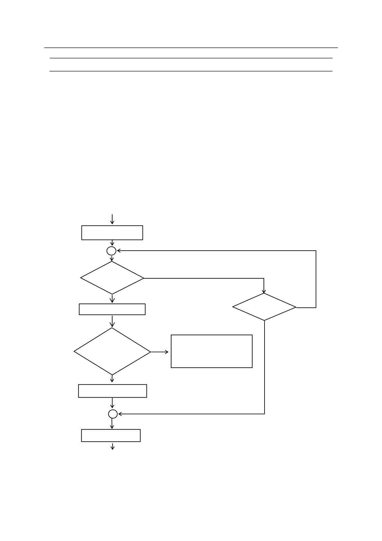
EXTCALL instruction is processed as shown in the following procedure:
1. Outputs JUMP-ST signal, allowing input at an external program.
2. Waits for JUMP-ON signal to be input.
3. When JUMP-ON is input, the program number input by RPS-CODE is read. If the number
input is 100 or higher, programs pgxxx are called. If the number is 99 - 10, programs pgxx
are called and if the number is smaller than 9, pgx.
JUMP-ST output
JUMP䠉ON
OFF
input
ON
OFF
JUMP-OFF?
read RPS code
Error (P1014)
current program
Yes Cannot execute because the
= new program
ON
program is already in use.
?
No
change program
JUMP-ST OFF
6-79
6. Program Instructions
[ NOTE ]
This instruction can be skipped by entering the CONTINUE NEXT command when
waiting for JUMP_ON signal.
This instruction is effective only when RPS mode is ON and the RPS signal is set as
software dedicated signal. An error occurs if this instruction is executed when
RPS is not defined as a dedicated signal.
If RPS mode is OFF, this instruction is ignored.
EXTCALL is used to call a subroutine. After the completion of this subroutine (or
when a RETURN instruction is processed in the subroutine), the execution returns
to the original program.
6-80

6. Program Instructions
ON mode signal number CALL program name, priority
ON mode signal number GOTO label, priority
ONI mode signal number CALL program name, priority
ONI mode signal number GOTO label, priority
Function
Monitors the specified external input signal or internal signal and upon input of the signal,
branches to the specified subroutine (CALL) or jumps to the specified label (GOTO).
ONI stops the current motion instruction, while ON waits for the current motion to be completed
before jumping to the subroutine or label.
Parameter
Mode
(not specified)
Monitors the rising and trailing edges of the specified signal.
/ERR (option)
Returns an error if the status of the signal already meets the set
condition when monitoring starts.
/LVL (option)
Immediately jumps to the specified subroutine or label if the status of
the signal already meets the set condition when monitoring starts.
Signal number
Specifies the number of the signal to monitor.
If the number is positive, the rising edge of signal or the change from OFF to ON is monitored.
If the number is negative, the trailing edge or the change from ON to OFF is monitored.
Acceptable signal numbers
External input signal
1001 - actual number of signals
Internal signal
2001 - 2960
Program name
Specifies the name of the subroutine to branch to when the specified signal is input. If omitted,
the program goes on to the next step in the program and does not branch to a subroutine.
Label
Specifies which label to jump to when the specified signal is input.
Priority
Specifies the priority of the program, setting range: 1 to 127. If not specified, 1 is assumed.
The greater the number is, the higher the priority becomes. Priority is ignored when a label is
6-81
6. Program Instructions
entered as the destination.
Explanation
For ON…CALL instruction, if change is detected in the monitored signal, the program is
interrupted and the specified subroutine is executed. This functions the same as CALL
instruction after the monitored signal is detected.
(See also 6.5 CALL program instruction).
If the RETURN instruction is executed in the called subroutine, the execution returns to the
program step after the step that was running before the subroutine was called (See also 11.3
External Interlock.)
ONI instruction can be used only in robot motion programs and not in PC programs.
Signal monitoring is canceled in any of the following cases:
1. IGNORE instruction is executed for the signal specified in ON and ONI instructions.
2. The ON and ONI instructions are executed and the program has branched to a subroutine.
3. A new ON or ONI instruction specifies the same signal as an earlier ON (ONI) instruction
(the older setting is canceled).
6-82
6. Program Instructions
[ NOTE ]
1. When monitoring the rising and trailing edge of the signal, the program branches
only when there is a change in the signal state. Therefore, if the leading edge is
to be detected, branching does not occur if that signal is already ON when the ON
instruction is executed. No branching will occur until the signal is turned OFF
then turned ON again.
2. To detect signal changes accurately, the signal must be stable for at least 50 msec.
3. Monitoring starts as soon as the ON (ONI) instruction is executed. Since in the
AS system, non-motion instructions are read and executed together with the
preceding motion, the monitoring starts at the same time as the motion right before
ON (ONI) instruction is executed.
4. The signals are not monitored while the program is not executed.
5. For ON and ONI instruction set in the main program, the signal status is monitored
also in the subroutine. However, when the signal signified in the subroutine is
input, the execution timing of the interruption process will be right after returning
to the main program. To execute the interruption process immediately in the
subroutine, set ON and ONI instructions in the subroutine in the same way as in the
main program.
6. The robot moves in standard motion type instead of motion type 2 while the signals
are monitored by ON instruction. Therefore, the robot motion may differ when
monitoring and not monitoring the signals.
Example
ONI -1001 CALL alarm
Monitors external input signal 1001(WX1). As soon as this signal
changes from ON to OFF (the signal number is negative so the
trailing edge is detected), the motion stops and the program
branches to subroutine “alarm”.
ON test CALL delay
Monitors the signal assigned to the variable “test”. If the signal
changes as desired (the condition depends on the value of “test”,
since it could be negative or positive), the program branches to
subroutine “delay” after execution of the current motion step is
completed. It returns to the original program when the subroutine
“delay” is completed.
6-83

6. Program Instructions
IGNORE signal number
Function
Cancels the monitoring of signals set by ON or ONI instruction.
Parameter
Signal numbers
Specifies the number of the signal to cancel monitoring.
Acceptable signal numbers
External input signal
1001 - actual number of signals
Internal signal
2001 - 2960
Explanation
This instruction nullifies the effect of the recent ON or ONI instruction set to the specified signal.
(See also 11.3 External Interlock.)
[ NOTE ]
The ON(ONI) monitoring function is only effective with binary I/O signals
actually installed as input signal.
Example
IGNORE
1005
Cancels monitoring of external input signal (Channel 5).
IGNORE test
Cancels the monitoring of the signal specified by the value of variable “test”.
6-84
6. Program Instructions
SCNT counter signal number = count up signal, count down signal,
counter clear signal, counter value
Function
Outputs counter signal when the specified counter value is reached.
Parameter
Counter signal number
Specifies the signal number to output. Setting range for counter signal numbers: 3097 to 3128.
Count up signal
Specified by signal number or logical expressions. Each time this signal changes from OFF to
ON, the counter counts up by 1.
Count down signals
Specified by signal number or logical expressions. Each time this signal changes from OFF to
ON, the counter counts down by 1.
Counter clear signals
Specified by signal number or logical expressions. If this signal is turned ON, the internal
counter is reset to 0.
Counter value
When the internal counter reaches this value, the specified counter signal is output. If “0”is
given, the signal is turned OFF.
Explanation
If the count up signal changes from OFF to ON when the SCNT command is executed, then the
internal counter value increases by 1. If the count down signal changes from OFF to ON, the
internal counter value decreases by 1. When the internal counter value reaches the value
specified in the parameter (counter value), the counter signal is output. If the counter clear
signal is output, value of the internal counter is set at 0. Each counter signal has its own
individual counter value. To force reset of the internal counter to 0, use SCNTRESET
command.
To check the states of signals 3001 to 3128, use the IO/E command. (Option)
See 5.7 also SCNT monitor command.
6-85
6. Program Instructions
SCNTRESET counter signal number
Function
Resets to 0 the internal counter value corresponding to the specified counter signal.
Parameter
Counter signal number
Selects the number of the counter signal to reset. Setting range for counter signal numbers: 3097
to 3128.
See also 5.7 SCNTRESET monitor command.
SFLK signal number = time
Function
Turns ON/OFF (flicker) the specified signal in specified time cycle.
Parameter
Signal number
Specifies the number of the signal to flicker. Setting range: 3065 to 3096.
Time
Specifies the time to cycle ON/OFF (real values). If a negative value is set, flickering is
canceled.
Explanation
The process of ON/ OFF is considered one cycle, and the cycle is executed in the specified time.
See also5.7 SFLK monitor command.
6-86
6. Program Instructions
SFLP output signal = set signal expression, reset signal expression
Function
Turns ON/OFF an output signal using a set signal and a reset signal.
Parameter
Output signal
Specifies the number of the signal to output. A positive number turns ON the signal; a negative
number turns it OFF. Only output signals can be specified (1 to actual number of signals).
Set signal expression
Specifies the signal number or logical expression to set the output signal.
Reset signal expression
Specifies the signal or logical expression to reset the output signal.
Explanation
If the set signal is ON, the output signal is turned ON. If the reset signal is ON, the output signal
is turned OFF. If both the set and reset signal are ON, then the output signal turns OFF. The
output signal is turned ON or OFF when the SFLP command is executed, and not when the set
signal or the reset signal is turned ON.
See also 5.7 SFLP monitor command.
6-87
6. Program Instructions
SOUT signal number = signal expression
Function
Outputs the specified signal when the specified condition is set.
Parameter
Signal number
Specifies the number of the signal to output. Only output signals can be specified (1 to actual
number of signals).
Signal expressions
Specifies a signal number or a logical expression.
Explanation
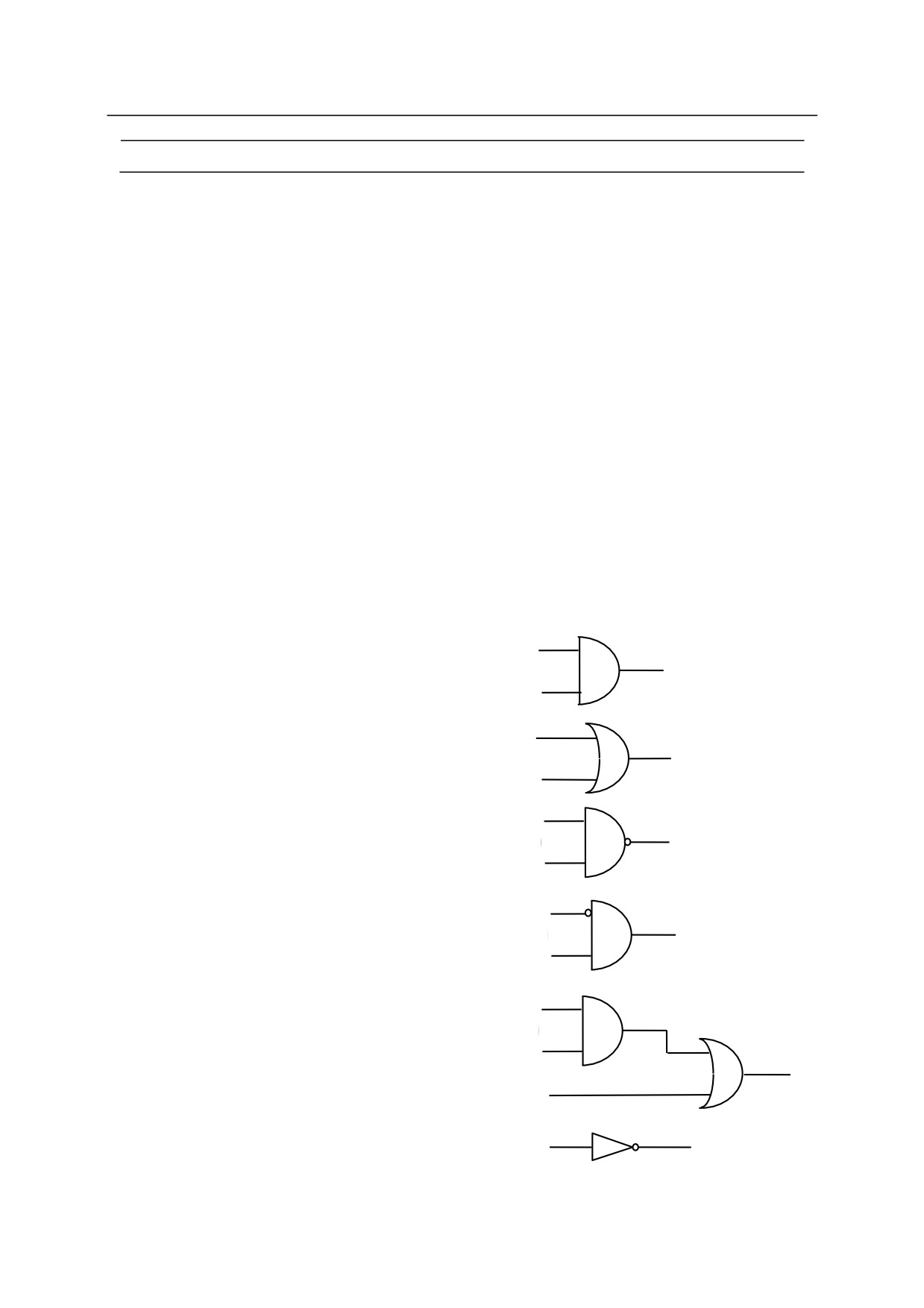
This instruction is for logical calculation of signals. Logical expressions such as AND and OR
are used. The specified signal is output when that condition is set. (See also 5.7 SOUT monitor
command.)
Example
1001
SOUT 1 = 1001 AND
1002
1
1002
1001
SOUT 1 = 1001 OR
1002
1
1002
1001
SOUT 1 = 1001 AND
1002
1
1002
SOUT
1 = NOT(1001 AND
1002)
1001
1
SOUT 1 = 1001 AND
1002
1002
1001
1002
SOUT 1 = (1001 AND
1002) OR
1003
1
1003
SOUT 1 = 1001 or SOUT
1= 1001 or
1001
1
SOUT 1 = NOT(1001)
6-88

6. Program Instructions
STIM timer signal = input signal number, time
Function
Turns ON the timer signal if the specified input signal is ON for the given time.
Parameter
Timer signal
Selects the signal number to turn ON. Setting range: 3001 to 3064.
Input signal number
Specifies in whole numbers the input signal number or logical expression to monitor as a
condition to turn ON the timer signal. The value cannot exceed the number of signals actually
installed.
Time
Specifies in real values the time (sec) the input signal is to be ON.
See also 5.7 STIM monitor command.
SETPICK
time1, time2, time3, time4, 䈈, time8
SETPLACE
time1, time2, time3, time4, 䈈, time8
Option
Function
Sets the time to start clamp close control (SETPICK) or clamp open control (SETPLACE) for
each of the 8 clamps.
Parameter
Time 1 to 8
Sets the control time to open/close clamps 1 to 8 in seconds. Setting range: 0.0 to 10.0 seconds.
Explanation
See also CLAMP instruction.
6-89
6. Program Instructions
CLAMP clamp number 1, clamp number 2, clamp number 3,
clamp number 4,
……, clamp number 8
Option
Function
Outputs clamp signal for opening/ closing the hand specified by the parameter clamp number x.
The output timing is set by the SETPICK/SETPLACE instruction; i.e. the signal is output x
seconds before the current motion is completed.
Parameter
Clamp number 1 to 8
Specifies the clamp number. If the number is positive, the robot hand is opened. If the number
is negative, the robot hand is closed.
Explanation
This instruction outputs signals to the control valve to open and close the pneumatic hand. The
signal is output immediately if the robot is not in motion, or if the remaining motion time is less
than the time set by SETPICK/SETPLACE instructions. The signal is output when the axes
coincide if the superposing of the next motion begins before the time set by
SETPICK/SETPLACE instructions is reached. If an irrational setting such as “CLAMP 1, 1”
is made, the latter clamp number will be valid.
Example
12 SETPICK 4, 3, 2, 1
13 SETPLACE 0.2, 0.4, 0.6, 0.8
14 LMOVE a
15 CLAMP 1, 2, 3, 4
By executing the above program, the robot will move as follows:
Closes clamp 2, 3 seconds before reaching pose a.
Closes clamp 3, 2 seconds before reaching pose a.
Opens clamp 4, 0.8 seconds before reaching pose a.
Opens clamp 1, 0.2 seconds before reaching pose a.
6-90
6. Program Instructions
HSENSESET no. = input signal number, output signal number,
signal output delay time
Option
Function
Declares the starting of signal detection to AS system. When this instruction is executed, AS
system starts to watch the sensor signal and accumulates the data such as pose, etc, into the buffer
memory at signal transaction. The data saved in the buffer memory can be read using HSENSE
instruction. Buffer memory can save up to 20 data.
Parameter
No.
Specifies the number for the monitoring results. Up to 2 input signals can be monitored.
Instruction for each signal is written as HSENSESET 1 or HSENSESET 2. Acceptable range is
1 or 2.
Input signal number
Set the signal number to monitor. Setting zero (0) terminates the monitoring.
Output signal number
Set the number of the signal to be output after system gets the joint angle. The specified signal
turns ON for 0.2 seconds. This may be omitted.
Signal output delay time
Set the time to delay the output of signal after acquiring the pose data. Acceptable range is 0 to
9999 ms. This may be omitted.
[ NOTE ]
Even when the controller power becomes OFF during watching, buffer
memory keeps the read data. It is possible to read the kept data by HSENSE
instruction after turning ON㻌 the controller power again. 㻌 However, watching
does not restart automatically, so HSENSESET should be executed again.
See also 5.7 HSENSESET monitor command.
Example
HSENSESET 1 = wx_sens
Starts watching for input signal wx_sens.
6-91
6. Program Instructions
HSENSE no. result variable, signal status variable,
pose variable, error variable, memory remainder variable
Option
Function
Reads the data saved in the buffer memory by HSENSESET instruction.
Parameter
No.
Specifies the monitoring number. To read data saved by HSENSESET 1 specify HSENSE 1.
To read data saved by HSENSESET 2, specify HSENSE 2.
Result variable
Specifies the name of the real variable to which the watch result is assigned. After executing
HSENSE instruction, numerical value is assigned to this variable. Zero (0) is assigned to this
variable when AS system does not detect the signal transaction.
-1 is assigned to this variable
when AS system detects the signal transaction.
Signal status variable
Specifies the name of the real variable to which the status of signal transaction is assigned.
After executing HSENSE instruction, a numerical value is assigned to this variable. When the
signal(s) is turned from OFF to ON, ON (-1) is assigned. When the signal(s) is turned from ON
to OFF, OFF (0) is assigned to this variable.
Pose variable
Specifies the name of the pose variable to which the joint values at time of HSENSE signal input
are assigned.
Error variable
Specifies the name of the real variable to which the buffer overflow error result is assigned.
When no error occurs, 0 is assigned to this variable. When buffer memory overflows, a
numerical value (other than 0) is assigned to this variable. The buffer memory overflows after
accumulating data from more than 20 transactions.
Memory remainder variable
Specifies the name of the real variable to which the number of used memory in the buffer is
assigned. The value assigned to this variable shows the number of memory in the buffer that is
already used. When only one memory is used, 0 will be assigned to the variable. When all
the memories are used, the value of the variable will be 19.
6-92
6. Program Instructions
Example
In this program, sensor signal wx_senser is monitored while the robot moves from
#p2_1 to
#p4_1 and the pose data of JT3 is saved in the array hsens_jt[ ] when the signal is detected. This
program uses many local variables (local variable names are written with a period (.) at the
beginning of the name).
.err = 0
;Initialize
IF SIG(wx_senser) THEN
;When sensor signal keeps ON
.err=4
;Incorrect starting point
RETURN
END
;
HSENSESET 1 = wx_senser
;Start watching
JMOVE #p2_1
;Move to starting point
BREAK
SPEED sens_sp
ABS.SPEED ON
JMOVE #p4_1
;Move to finishing point
.num = 0
loop:
HSENSE 1 .stat,hsens_onoff[.num+1],#hsens[.num+1] ,.serr,.rest
IF .serr <> 0 THEN
.err = 3
;Memory buffer over㻌 "(HSENS)"
RETURN
END
IF .stat==ON THEN
hsens_jt[.num+1] = DEXT(#hsens[.num+1],3)
;Save pose in Z direction when signal detected
.num = .num + 1
END
IF .rest GOTO loop
;Loop when buffer keeps data
IF DISTANSE(DEST,HERE) > 0.1 GOTO loop
;
HSENSESET 1 = 0
;Finish watching
6-93
6. Program Instructions
6.8 MESSAGE CONTROL INSTRUCTIONS
PRINT
Displays message on terminal.
TYPE
Displays message on terminal.
PROMPT
Displays message on terminal and waits for input from the keyboard.
IFPWPRINT
Displays specified character string in a display window.
IFPWOVERWRITE Displays by overwriting character string in a display window.
IFPLABEL
Sets the labels for the icons on interface panel.
IFPTITLE
Sets the title for the specified page of the interface panel.
SETOUTDA
Sets analog output environment. (Option)
OUTDA
Outputs voltage at set conditions. (Option)
6-94

6. Program Instructions
PRINT device number: print data, …….
TYPE device number: print data, …….
Function
Displays on the terminal the print data specified in the parameter.
Parameter
Device number
Select the device to display the data from below:
0: All terminals that are connected
1: Personal computer
2: Teach pendant
3: - 5: Terminals connected via Ethernet
If not specified, the data will be displayed on the currently selected device.
Print data
Select one or more from below. Separate the data with commas when specifying more than one.
(1) Character string
e.g.
“count =”
(2) Real value expressions (the value is calculated and displayed)
e.g.
count
(3) Format information (controls the format of the output message) e.g.
/D, /S
A blank line is displayed if no parameter is specified.
Explanation
See 5.8 PRINT/TYPE Monitor Command.
[ NOTE ]
If the MESSAGES switch is OFF, no message appears on the terminal screen.
6-95
6. Program Instructions
PROMPT device number: character string, variables
Function
Displays the specified character strings on the terminal followed by the prompt ”>” and waits for
input from the keyboard.
Parameter
Device number
Select the device to display the data from below:
1: Personal computer
2: Teach pendant
If not specified, the data will be displayed on the currently selected device.
Character string
Specifies the characters to display on the terminal.
Variables
Specifies to which variable the data input from the keyboard is substituted. It can be a series of
real variables or a single string variable.
Explanation
The specified character strings are displayed on the terminal and waits for data and
to be input
from the keyboard.
The data input is processed in one of the following ways.
1. When PROMPT is used to ask for values for a series of real variables, the system reads the
input line as a series of numbers separated by spaces or commas. Each input number is
converted into internal expressions according to its notation, and then they are assigned to the
variables one by one.
2. If the number of values input is greater than the number of variables, the excess values are
ignored. If the number of values input is less than the number of variables, “0” is assigned
to the remaining variables. If data other than numeric values are input, an error occurs, and
the program stops execution. To avoid confusion and error, it is advisable that one
PROMPT instruction is used to assign one value to one variable.
When using a character string variable as the variable parameter for PROMPT, the characters
input are read as a single data unit and all the characters are assigned to the character string
variable. At the screen prompt, if only the
key or
CTRL +
C is pressed, “0” is assigned to real
6-96
6. Program Instructions
variables, and a null string is assigned to character string variables.
If “2” is entered for device number, the teach pendant screen changes automatically to keyboard
screen. Press <NEXT PAGE> to return to the regular screen.
Example
The character string in quotations is displayed on the terminal, and asks for data to be input.
When the data (number of parts) is input and the
key is pressed, the value entered is substituted
to the variable “part.count”. The program execution then proceeds.
PROMPT "Enter the number of parts: ", part.count
The instruction below asks for the value of a character string variable. Alphanumeric characters
can be input without causing an error.
PROMPT "Enter the number of parts: ", $input
6-97
6. Program Instructions
IFPWPRINT window number, row, column, background color,
label color, = “character string”, “character string”, ……
Option
Function
Displays the specified character string in the string window set in Auxiliary Function 0509
(Interface panel screen).
Parameter
Window number
Corresponds to the window number specified in Auxiliary Function 0509 as the window
specification used to display the string. Select from 1to 8 (standard).
Row
Specifies the row in the selected window to display the string. Enter from 1 to 4; available rows
depend on the window size. If not specified, 1 is assumed.
Column
Specifies the column in the selected window to display the string. Enter from 1 to 70, though
available columns depend on the window size. If not specified, 1 is assumed.
Background color
Selects the background color of the selected window. Colors are numbered from 0 to 15. If
not specified, the background is white.
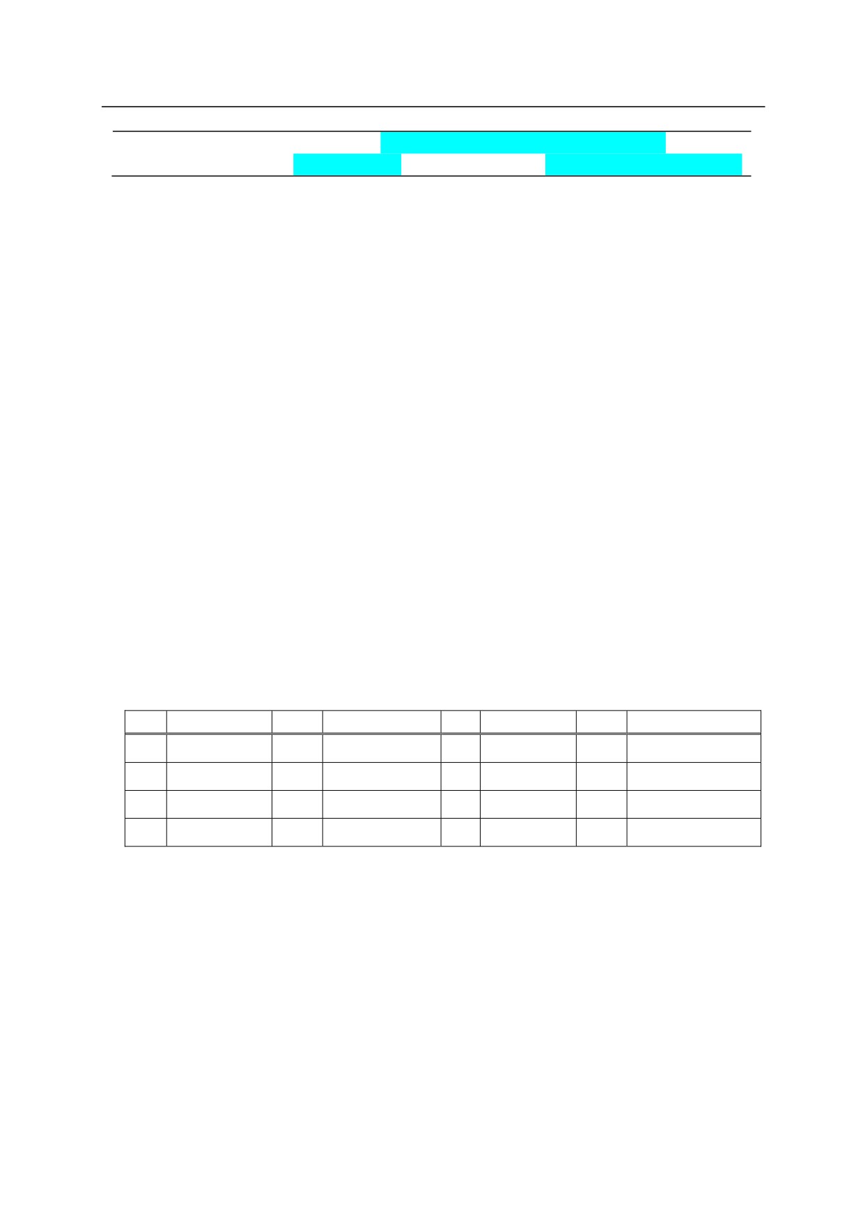
No.
Color
No.
Color
No.
Color
No.
Color
0
Grey
4
Green
8
Pink
12
Navy
1
Blue
5
Pale Blue
9
White
13
Reddish Brown
2
Red
6
Yellow
10
Black
14
Deep Green
3
Orange
7
White
11
Cyan
15
Lavender
Label color
Selects the color of the characters displayed. Colors are numbered from 0 to 15 (See chart
above). If not specified, the characters are displayed in black.
Character string
Specifies the character string to display. All strings after the first string are displayed on the next
row starting at specified column. Execution of IFWPRINT clears the non-display area in the
specified window.
6-98