Kawasaki Robot Controller E Series. Reference Manual (2015) - page 8
6. Program Instructions
DRAW X translation, Y translation, Z translation
X rotation, Y rotation, Z rotation, speed
TDRAW X translation, Y translation, Z translation
X rotation, Y rotation, Z rotation, speed
Function
Moves the robot in linear movement from the current pose and at the specified speed, the distance
specified in the direction of the X, Y, Z axes and rotates the specified amount around each axis.
DRAW instruction moves the robot based on the base coordinates, TDRAW instruction moves
the robot based on the tool coordinates.
Parameter
X translation
Specifies the amount to move on the X axis in mm. If not specified, 0 mm is entered.
Y translation
Specifies the amount to move on the Y axis in mm. If not specified, 0 mm is entered.
Z translation
Specifies the amount to move on the Z axis in mm. If not specified, 0 mm is entered.
X rotation
Specifies the amount to rotate around the X axis in deg. Acceptable range is less than 180.
If not specified, 0 deg is entered.
Y rotation
Specifies the amount to rotate around the Y axis in deg. Acceptable range is less than 180.
If not specified, 0 deg is entered.
Z rotation
Specifies the amount to rotate around the Z axis in deg. Acceptable range is less than 180.
If not specified, 0 deg is entered.
Speed
Specifies the speed in %, mm/s, mm/min, cm/min, or s. If not specified, the robot moves at the
program speed.
6-9
6. Program Instructions
Explanation
The robot moves from the current pose to the specified pose in linear movement.
Example
DRAW 50,,-30
Moves from the current pose in linear motion 50 mm in the direction of
the X axis and -30 mm in the direction of the Z axis of the base
coordinates.
6-10

6. Program Instructions
ALIGN
Function
Moves the Z axis of the tool coordinates to be parallel with the closest axis of the base
coordinates.
Explanation
In each application, if the reference motion direction is set along the tool Z direction, DO ALIGN
enables easy alignment of the tool direction to the base coordinates before teaching the pose data.
HMOVE pose variable, clamp number
Function
Moves the robot to the specified pose. The robot moves in hybrid motion: major axes in linear
interpolation, and the wrist joints in joint interpolation.
Parameter
Pose variable
Specifies the destination of the robot motion.
(Can be in transformation values, compound
transformation values, joint displacement values or pose information functions.)
Clamp number
Specifies the clamp number to open or close at the destination pose. Positive number closes the
clamp, and negative number opens it. Any clamp number can be set up to the maximum
number set via HSETCLAMP command (or the auxiliary function 0605). If omitted, the clamp
does not open or close.
Explanation
This instruction moves the robot in linear interpolated motion. The origin of the tool
coordinates draws a linear trajectory. However, the wrist joints move in joint interpolation.
This instruction is used when the robot is to be moved in linear motion but the angles of the wrist
joints change greatly between the beginning and end of the motion.
6-11
6. Program Instructions
XMOVE mode pose variable TILL signal number
Function
Moves the robot towards the specified pose in linear movement, stops motion when the specified
signal condition is set even if the pose has not been reached, and skips to the next step.
Parameter
Mode
(Not specified)
Monitors for the rising or trailing edge of the specified input signal. Positive signal number
monitors rising edge, and negative number monitors trailing edge.
/ERR (Option)
Returns an error if the signal condition is already set when the monitoring starts.
/LVL (Option)
Immediately skips to the next step if the signal condition is already set when the monitoring
starts.
Pose variable
Specifies the destination pose of the robot motion. (Can be in transformation values, compound
transformation values, joint displacement values or pose information functions.)
Signal number
Specifies the number of external input signal or internal signal.
Acceptable signal numbers
External input signal
1001 to actual number of installed signals or 1064 (the smaller
of the two).
Internal signal
2001 to 2960
6-12
6. Program Instructions
[ NOTE ]
. When monitoring the rising and trailing edge of the signal, the program branches only when
there is a change in the signal status. Therefore, if the rising edge of signal is monitored and
the signal is ON at the time XMOVE is executed, the program will not be interrupted until that
signal turns OFF and then ON again.
The input signal should be stable for at least 50 msec for accurate monitoring.
Example
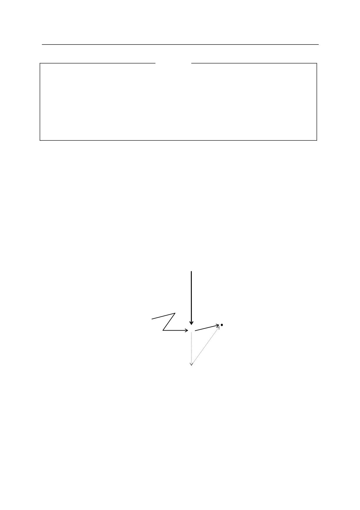
XMOVE end TILL
1001
LMOVE skip
Moves from the current pose to pose “end” in linear motion. As soon as the input signal 1001 is
turned ON, the program execution skips to the next step (LMOVE skip) even if the robot has not
reached “end”.
X (current pose)
Input signal
WX1 (1001)
skip
×
end
6-13
6. Program Instructions
C1MOVE pose variable, clamp number
C2MOVE pose variable, clamp number
Option
Function
Moves the robot to the specified pose following a circular path.
Parameter
Pose variable
Specifies the destination of the robot motion.
(Can be in transformation values, compound
transformation values, joint displacement values or pose information functions.)
Clamp number
Specifies the clamp number to open or close at the destination pose. Positive number closes the
clamp, and negative number opens it. Any clamp number can be set, up to the maximum
number set via HSETCLAMP command (or the auxiliary function 0605). If omitted, the clamp
does not open or close.
Explanation
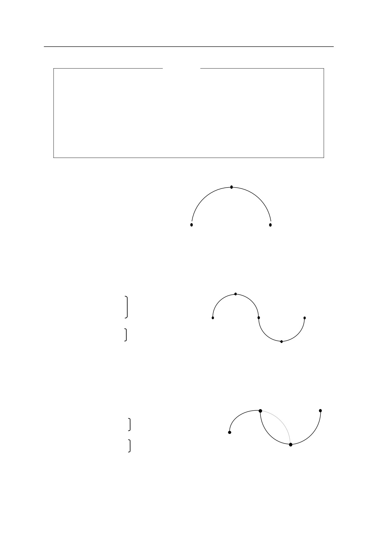
C1MOVE instruction moves to a point midway on the circular trajectory, C2MOVE instruction
moves to the end of the trajectory.
To move the robot in a circular interpolated motion, three poses must be taught. The three poses
differ in C1MOVE and C2MOVE instructions.
C1MOVE䠖
1. Pose of the latest motion instruction.
2. Pose to be used as the parameter of C1MOVE instruction.
3. Pose of the next motion instruction. (C1MOVE or C2MOVE instruction)
C2MOVE䠖
1. Pose of the latest C1MOVE instruction.
2. Pose of the motion instruction before C1MOVE instruction.
3. Pose of C2MOVE instruction.
6-14
6. Program Instructions
[ NOTE ]
The following motion instructions are needed before the C1MOVE instruction:
ALIGN, C1MOVE, C2MOVE, DELAY, DRAW, TDRAW, DRIVE, HOME,
JMOVE, JAPPRO, JDEPART, LMOVE, LAPPRO, LDEPART, STABLE,
XMOVE
C1MOVE instruction must be followed by C1MOVE or C2MOVE instruction.
C1MOVE instruction must precede a C2MOVE instruction.
Example
c2
JMOVE c1
C1MOVE c2
C2MOVE c3
c3
c1
The robot moves in joint interpolated motion to c1 and
then moves in a circular interpolated motion following the
arc created by c1, c2, c3.
b
JMOVE
#a
C1MOVE #b
arc a,b,c
C2MOVE #c
c
e
a
C1MOVE #d
arc c,d,e
C2MOVE #e
d
p2
p4
LMOVE
#p1
arc p1,p2,p3
C1MOVE #p2
p1
C1MOVE #p3
arc p2,p3,p4
C2MOVE #p4
p3
6-15
6. Program Instructions
6.2 SPEED AND ACCURACY CONTROL INSTRUCTIONS
SPEED
Sets the motion speed (program speed).
ACCURACY
Sets the accuracy range.
ACCEL
Sets the acceleration.
DECEL
Sets the deceleration.
BREAK
Holds execution of the next step until the current motion
is completed.
BRAKE
Stops the current motion and skips to the next step.
BSPEED
Sets the block speed. (Option)
REFFLTSET
Specifies the moving average for robot command values.
REFFLTRESET
Resets the robot’s moving average span.
FFSET
Sets the speed/ acceleration feed forward gain.
FFRESET
Resets the robot speed/ acceleration feed forward gain.
6-16
6. Program Instructions
SPEED speed, rotational speed, ALWAYS
Function
Specifies the robot motion speed.
Parameter
Speed
Specifies the program speed. Usually it is specified in percentages between 0.01 to 100 (%).
Absolute speed can be set by specifying the speeds with these units: MM/S and MM/MIN. The
unit S (seconds) specifies the motion time. The input range for motion time is 0.1 S to 3601 S.
If the unit is omitted, it is read as percent (%).
Rotational speed (Option)
Specifies the rotational speed of the tool orientation in linear and circular interpolated motions.
Usually it is specified in percentages between 0.01 to 100 (%). Absolute speed can be set by
specifying the speed with these units: DEG/S and DEG/MIN. If the unit is omitted, it is read as
percent (%). If this parameter is omitted, the rotational speed is set at 100 %.
ALWAYS
If this parameter is entered, the speed set in this instruction remains valid until the next SPEED
instruction is executed. If not entered, the speed is effective only for the next motion instruction.
Explanation
The actual speed of the robot motion is determined by the product of the monitor speed and the
motion speed set by this instruction (Monitor speed Program speed). However, full speed is
not guaranteed in cases such as below:
1.㻌 when the distance between the two taught poses is too short,
2.㻌 when a linear motion exceeding the maximum speed of axis rotation is taught.
The motion speed is determined differently in joint interpolated motion and linear movement. In
joint interpolated motion, the motion speed is determined as a percentage of the maximum speed
of each axis. In linear movement, the motion speed is determined as a percentage of the
maximum speed at the origin of the tool coordinates.
When the speed is specified in distance per unit time or in seconds, the speed in linear movement
at the origin of the tool coordinates is set. When moving in joint interpolated motions, set the
speed in percent.
(Even if the speed is set in absolute speed or in motion time, the robot will not
move in the set speed. Instead, the speed is processed as a percentage of the given value to the
6-17
6. Program Instructions
maximum speed.)
The absolute speed expressed in values with MM/ S and MM/MIN, and time specified speed
expressed in values with S, describe the speed when the monitor speed is 100 %. If the monitor
speed is decreased, these speeds decrease in the same proportion.
[ NOTE ]
Even if the product of program speed and the speed set by SPEED command (monitor
speed) exceeds 100 % the actual motion speed does not exceed 100 %.
The rotational speed cannot be set without the rotational speed control option ON. If the
option is not ON, error occurs.
Example
The speed is set as follows when the monitor speed is 100%:
SPEED
50
Sets the speed of the next motion to 50 % of the maximum speed.
SPEED 100
Sets the speed of the next motion to 100 % of the maximum speed.
SPEED 200
Sets the speed of the next motion to 100 % of the maximum speed
(speed over 100 % is considered 100 %).
SPEED 20MM/S ALWAYS
The speed of the origin of the tool coordinate (TCP) is set at 20
mm/sec until it is changed by another SPEED instruction (when
the monitor speed is 100 % ).
SPEED 6000 MM/MIN
Sets the speed of the next robot motion to 6000 mm / min.
(The
speed of linear motion of the origin of the tool coordinates).
SPEED
5 S
Sets the speed of the next robot motion so that the destination is
reached in 5 seconds. (The speed of linear motion of the origin of the
tool coordinates).
6-18
6. Program Instructions
ACCURACY distance ALWAYS㻌 FINE
Function
Sets the accuracy when determining the robot pose.
Parameter
Distance
Specifies the distance of accuracy range in millimeters.
ALWAYS
If this parameter is entered, the accuracy setting remains valid until the next ACCURACY
instruction is executed. If not entered, the accuracy setting is valid only for the next motion
instruction.
FINE
If this parameter is entered, the robot pose is determined only when the current values match the
taught pose regardless of the “distance” parameter setting.
Explanation
When the parameter ALWAYS is entered, all the proceeding motions are controlled by the
accuracy set by this instruction. The default accuracy setting is 1 mm.
There is a limit to the effect of the accuracy setting, since in AS system the accuracy check is not
started until the robot decelerates as it approaches the taught pose.
(See also 4.5.4㻌 Relation
between CP Switch and ACCURACY, ACCEL, DECEL Instructions.)
[ NOTE ]
When the accuracy is set at 1 mm, the robot sets the pose after each motion instruction,
coming to a pause in between the motion segments. To assure CP motion, set the
accuracy range greater.
Setting the accuracy range too small may result in non-coincidence of the axes.
The accuracy set by this instruction is not the accuracy for repetition but for
positioning the robot; therefore do not set values of 1 mm or less.
Example
ACCURACY
10 ALWAYS The accuracy range is set at 10 mm for all motion instructions
after this instruction.
6-19
6. Program Instructions
ACCEL acceleration ALWAYS
DECEL deceleration ALWAYS
Function
Sets the acceleration (or deceleration) of the robot motion.
Parameter
Acceleration (ACCEL) / deceleration (DECEL)
Specifies the acceleration or deceleration in percentages of the maximum acceleration
(deceleration). Acceptable range is from 0.01 to 100. Values over this limit are assumed as
100, values below the limit are assumed as 0.01.
ALWAYS
If this parameter is entered, the acceleration (or deceleration) here is valid until the next ACCEL
(or DECEL) instruction. If not entered, this instruction affects only the next motion instruction.
Explanation
ACCEL instruction sets the acceleration when the robot starts a motion as a percentage of the
maximum acceleration. DECEL instruction sets the deceleration when the robot is at the end of
a motion as a percentage of the maximum deceleration.
Example
ACCEL
80 ALWAYS The acceleration is set at 80% for all motions after this instruction.
DECEL
50
The deceleration for the next motion instruction is set at 50 %.
6-20
6. Program Instructions
BREAK
Function
Holds execution of the next step in the program until the current robot motion is completed.
Explanation
This instruction has the following two effects:
1. Holds the execution of the program until the robot reaches the destination of the current motion
instruction.
2. The CP motion from the current motion to the next motion is interrupted. The robot comes to
a stop in between the motion segments.
BRAKE
Function
Stops current robot motion.
Explanation
Stops current robot motion immediately and skips to the next step in program.
6-21
6. Program Instructions
BSPEED speed
Option
Function
Sets the robot’s motion speed (block speed). The robot motion speed is calculated by
monitor speed program speed block speed.
Parameter
Speed
Sets the speed (acceptable range: 1 to 1000%). The speed set by this instruction is valid until the
next BSPEED instruction is executed.
Explanation
The robot motion speed is calculated by monitor speed program speed block speed.
However, the total speed cannot exceed 100 %. Values up to 1000 can be entered for each
speed, but if the total speed exceeds 100 %, it is automatically cut down to 100 %. For example,
if the monitor speed is 100 % and the program speed 50 %, the motion speed is calculated by
100 %50 %block speed. If the block speed is less than 200 %, the speed varies following the
result of the above expression, but if it is over 200 %, the motion speed always becomes 100 %.
[ NOTE ]
1. When the program selection is reset, and a new program is executed (e.g. via EXECUTE
command or by program selection via the teach pendant), the block speed is set at the
default value of 100 %. When the program is selected externally, the block speed is set at
the default value if the program is selected by external program reset, but not with RPS and
JUMP signals.
2. Note that the robot may not move in the specified program speed if the program is not
executed from the beginning of the program or when the steps are skipped. In the example
below, the robot is stopped while in step 3 and the motion is resumed after jumping to step
25. Then, the block speed at step 25 will be the speed of block 1.
Step 1
BSPEED block1
; Sets the speed for block 1.
Step 2
Joint Speed 9……
Step 3
Linear Speed 9……
Step 12
BSPEED block2
; Sets the speed for block 2.
Step 13
Joint Speed 9……
Step 14
Linear Speed 9……
Step 24
BSPEED block3
; Sets the speed for block 3.
Step 25
Joint Speed 9……
Step 26
Linear Speed 9……
6-22
6. Program Instructions
Example
Write the program as follows so that the speed is changed by 4 bits from an external signal.
a=BITS(first signal for external speed selection,4)
BSPEED block1[a]
The following program enables selecting speed from an external device:
BSPEED block1
; Sets the default value for the block.
IF SIG(External_speed ON)THEN
; Determines if external speed selection is enabled.
a=BITS(first signal for external speed selection,4) ; Acquires the number used for external selection
IF(a<11)THEN
; Setting not possible if a is 11+
BSPEEDblock11[a]
; Sets the selected block speed.
END
END
Joint Speed 9……
; Moves in selected block speed.
Joint Speed 9……
Real number variable “block 1” must be defined in advance.
block1=50
block11[0]=10
block11[1]=20
block11[2]=30
block11[3]=40
For example, if the first signal for external program selection is 1010, and the signals are inputs
as:
1010䞉䞉䞉OFF
1011䞉䞉䞉ON
1012䞉䞉䞉OFF
1013䞉䞉䞉OFF
then a = 2, therefore block 11[2] is chosen and the motion speed becomes 30 %.
6-23
6. Program Instructions
REFFLTSET joint value moving average span, position moving average span ,
orientation moving average span , signal moving average span
Function
Specifies the moving average for robot command values. This instruction is valid only when the
moving average option for command value is enabled.
Parameter
Joint value moving average span
Specifies the moving average span for the joint angles when the robot is moving in joint
interpolation motion. Unit: [ms]. Acceptable range: integer between 1 through 254. The
specified value is rounded up depending on the AS system control cycle.
(This is the same for
parameters 2 -4).
Position moving average span
Specifies the moving average span for position values when the robot is moving in linear
interpolation or circular motion. Unit: [ms]. Acceptable range: integer between 1 through 254.
When omitted, the same value as joint value moving average span is set.
Orientation moving average span
Specifies the moving average span for orientation values when the robot is moving in linear
interpolation or circular motion. Unit: [ms]. Acceptable range: integer between 1 through 254.
When omitted, the same value as position moving average span is set.
Signal moving average span (Option)
Specifies the moving average span for signal outputs. Unit: [ms]. Acceptable range: integer
between 1 through 254. When omitted, this parameter value is set by multiplying the ratio
between the default value of joint value moving average span and its current setting to the default
value of the signal moving average span.
[ NOTE ]
The relative relation between the above four parameters are balanced for the default
setting. Therefore, when making any modifications, it is usually only necessary to
specify the parameter for the joint value moving average span. This way, the relative
relation between the parameters will be kept adequate.
The default and current values for each parameter can be checked via
REFFLTSET_STATUS command.
6-24
6. Program Instructions
Explanation
Moving average span is set to make the robot reach the specified pose smoothly. When this
span is set longer, the robot’s vibration is reduced and the robot makes a smoother motion.
However, the cycle time will also become longer and there is a tendency that the robot takes a
greater shortcut than the taught path.
On the other hand, when the span is set shorter, the cycle time is shortened and the robot follows
a trajectory that is more precise to the taught path. However, the robot vibration tends to be
greater.
[ NOTE ]
Normally do not use this instruction, because using this instruction changes the dynamic
characteristics. When using this instruction, follow the below procedure:
䞉Gradually change the values, in about 8 ms increments, and confirm the robot motion after
making the changes.
䞉When checking the robot motion, start at a low monitor speed of about 20 % and
gradually raise the speed.
[ NOTE ]
The values set by executing this instruction apply to all robot motions, as is with SPEED
ALWAYS instruction. To reset to the default value, use REFFLTRESET instruction.
The continuous path motion between the current motion and the next motion instruction is
interrupted when REFFLTSET instruction is executed. That is, the two motions will not
be followed in a one consecutive motion, but the robot will stop once at the end of the first
motion before entering the second motion.
Example
REFFLTSET
64
Sets the robot’s joint value, position, and orientation average
span to 64 ms. The signal average span is set to the default
value.
REFFLTSET
64, 64, 64, 32
Sets the robot’s joint value, position, and orientation average
span to 64 ms and sets the signal average span to 32 ms.
6-25
6. Program Instructions
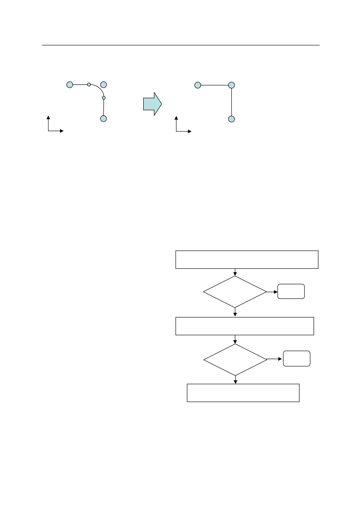
Average span between P1 and P2
䠙Default setting
p1
p2
p1
p2
Average span between
P2and P3=X1
Y
Y
p3
p3
X
X
Robot motion program
Robot motion program
JMOVE㻌 p1
JMOVE㻌 p1
LMOVE p2
LMOVE p2
LOMVE p3
REFFLTSET㻌 X1
LOMVE p3
Take the countermeasures for vibration following the below procedure:
1)
Reduce the vibration by reducing the acceleration and deceleration.
Use AS instructions ACCEL/ DECEL to change them.
For block teaching, change them via
Aux. 0301 Acceleration/
Deceleration setting.
(Aux.0301
1) Reduce acceleration/ deceleration
can be used only when [ACCEL and
DECEL] setting in Aux. 0399 is set
Yes
to [Enable].)
Problem
End
solved
When the vibration is not reduced or
No
the cycle time is too long, reset them
to the original setting and perform
2) Use REFFLTSET instruction.
the next adjustment.
Yes
Problem
2)
Smooth the robot motion via
End
solved
REFFLTSET instruction.
No
Set the moving average span larger via
REFFLTSET instruction.
3) Use FFSET instruction.
This is effective when the section
where the average span is set larger
(i.e. the section between
REFFLTSET and REFFLTRESET)
satisfies the below condition:
6-26
6. Program Instructions
䞉 There is more than one step.
䞉 Few steps that require axis coincidence with the current pose.㻌
䞉 There are many steps with short distance below 50 mm.
䞉 The accuracy setting is small in the motion step before REFFLTSET/REFFLTRESET
instruction.
It is recommended to adjust the acceleration and deceleration together with the moving
average span. Executing REFFLTSET instruction changes the robot’s path, so be careful
when confirming the motion.
When the vibration is not reduced or the cycle time is too long after using REFFLTSET
instruction and changing the acceleration and deceleration, reset the REFFLTSET instruction
and acceleration/ deceleration setting to the original setting and perform the next adjustment
using FFSET instruction. FFSET instruction is explained later in this section.
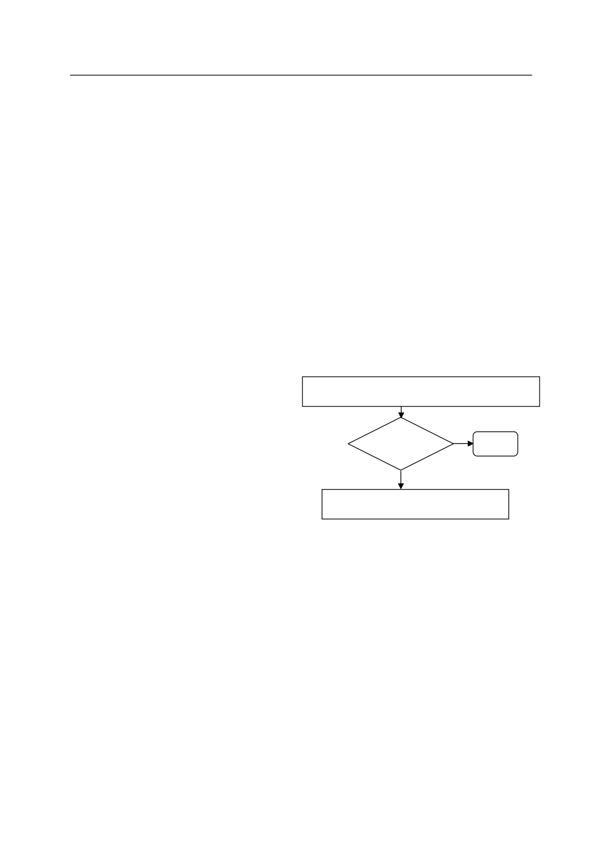
Take the countermeasures for accuracy following the below procedure:
1)
Confirm the path accuracy at a low speed.
1) Reduce acceleration/ deceleration
Use AS instruction SPEED or
speed instruction in block teaching
Yes
to change the speed.
Problem
End
solved
If the path accuracy does not
No
improve or the speed setting does
2) Use REFFLTSET instruction.
not match with the application
conditions , set the speed back to
the original setting and perform the
next adjustment.
2)
Improve the path accuracy via
REFFLTSET instruction.
Use REFFLTSET instruction to
reduce the moving average span
and improve the path accuracy.
The vibration tends to increase when this setting is done, so be careful when checking the
robot motion.
6-27
6. Program Instructions
REFFLTRESET
Function
Resets the robot’s moving average span to the default value.
Parameter
Resets to the default value the moving average span changed by REFFLTSET instruction.
As with the REFFLTSET instruction, the continuous path motion between the current motion and
the next motion instruction is interrupted when this instruction is executed. That is, the two
motions will not be followed in a one consecutive motion, but the robot will stop once at the end
of the first motion before entering the second motion.
Example
In the sample program below, the moving average span from p2 to p3 is X1, and the moving
average span between p3 to p1 is set at the default value.
Robot motion program
JMOVE㻌 p1
LMOVE p2
REFFLTSET㻌 X1
LOMVE p3
REFFLTRESET
JMOVE p1
6-28
6. Program Instructions
FFSET JT1 gain, JT2 gain, JT3 gain, JT4 gain, JT5 gain,
JT6 gain, JT7 gain, JT8 gain, JT9 gain
Function
Sets the speed/ acceleration feed forward gain for when the robot starts moving.
Parameter
JT 1 gain, JT 2 gain, JT 3 gain, JT 4 gain, JT 5 gain, JT 6 gain, JT 7 gain, JT 8 gain, JT 9 gain
Specifies the speed/ acceleration feed forward gain for each axis in real values. Acceptable
range: 0 -1 (valid to the third decimal place). Values for the axes other than JT1 can be omitted.
The values will be set as follow when omitted.
When parameters for robot axes are omitted:
Sets the same value as the setting for JT1.
When parameters for external axes are omitted: The ratio between the default and current value
of JT1 is multiplied to the default value for the
omitted external axis.
[ NOTE ]
The gains for the robot axes should be set equal to JT1. The default and current setting
for each parameter can be checked via FFSET_STATUS command.
Explanation㻌
When the speed/acceleration feed forward gain is set smaller, the robot’s vibration is reduced and
the robot makes a smoother motion. However, the cycle time will also become longer and there
is a tendency that the robot takes a greater shortcut than the taught path.
On the other hand, when the gain is set greater, the cycle time is shortened and the robot follows a
trajectory that is more precise to the taught path. However, the robot vibration tends to be
greater.
6-29

6. Program Instructions
[ NOTE ]
Normally do not use this instruction, because using this instruction changes the dynamic
characteristics. When using this instruction, follow the below procedure:
䞉Gradually change the values, in about 0.1 increments, and confirm the robot motion
after making the changes.
䞉When checking the robot motion, start with a low monitor speed of about 20 % and
gradually raise the speed.
This instruction changes the dynamic characteristics; therefore confirm the robot speed
does not change suddenly at the beginning and end of the modification.
[ NOTE ]
The values set by executing this instruction apply to all robot motions, as is with SPEED
ALWAYS instruction. To reset to the default value, use FFRESET instruction.
Example
FFSET㻌 0.5
㻌 㻌 Sets all the speed/ acceleration feed forward value to 0.5.
FFSET㻌 0.5,0.49
Sets the speed/ acceleration feed forward value to 0.5 for all the axes
except for JT2, and sets the speed/ acceleration feed forward value to 0.5
for JT2 to 0.49.
In the sample robot motion program below, the speed/ acceleration feed forward gain is changed
to 0.5 after axis coincidence in #p1.
JMOVE㻌 #p1
FFSET㻌 0.5
JMOVE #p2
FFRESET
JMOVE #p3
6-30
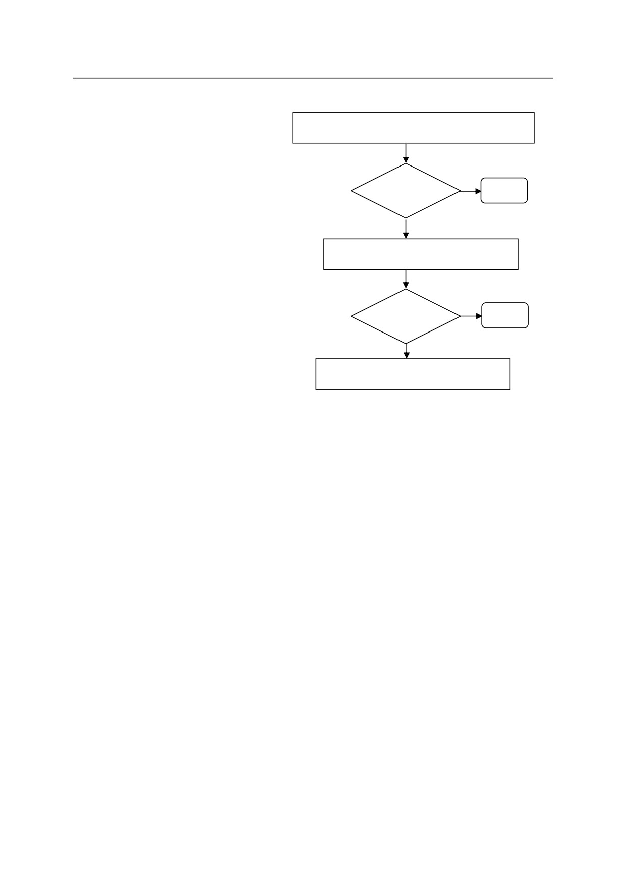
6. Program Instructions
Take the countermeasures for vibration
following the below procedure:
1) Reduce acceleration/ deceleration
1) Reduce the vibration by reducing
the deceleration.
Problem
End
Follow the procedures explained for
solved
Yes
REFFLTSET instruction.
No
2) Smoothen the motion via
2) Use REFFLTSET instruction.
REFFLTSET instruction.
Follow the procedures explained for
Yes
REFFLTSET instruction.
Problem
End
solved
3)
㻌 Smoothen the motion via FFSET instruction.
No
Set the speed/ acceleration feed
3) Use FFSET instruction.
forward gain via FFSET instruction
to smoothen the robot motion.
Using FFSET instruction changes
the robot path so carefully confirm
the robot motion after executing the
instruction.
6-31
6. Program Instructions
FFRESET
Function
Resets the robot speed/ acceleration feed forward gain to the default value.
Explanation
Resets the robot speed/ acceleration feed forward gain changed by FFSET instruction to the
default value. This works as setting the default value via FFSET instruction.
Example
In the sample robot motion program below, the speed/ acceleration feed forward gain is changed
to 0.5 after axis coincidence in #p1. The feed forward gain is reset to the default value after axis
coincidence in #p2.
JMOVE㻌 #p1
FFSET㻌 0.5
JMOVE #p2
FFRESET
JMOVE #p3
6-32
6. Program Instructions
Kawasaki Robot AS Language Manual
6.3 CLAMP CONTROL INSTRUCTIONS
OPEN
Outputs clamp open signal when next motion instruction begins.
OPENI
Outputs clamp open signal when current motion instruction is
completed.
CLOSE
Outputs clamp close signal when next motion instruction begins.
CLOSEI
Outputs clamp close signal when current motion instruction is
completed.
RELAX
Turns OFF clamp signals when next motion instruction begins.
RELAXI
Turns OFF clamp signals when current motion instruction is
completed.
OPENS
Output clamp open signal during execution of motion instruction.
CLOSES
Output clamp close signal during execution of motion instruction.
RELAXS
Turns OFF clamp signals during execution of motion instruction.
GUNON
Turns ON gun signal and controls gun output timing by distance.
(Option)
GUNOFF
Turns OFF gun signal and controls gun output timing by distance.
(Option)
GUNONTIMER
Controls gun output ON timing by timer. (Option)
GUNOFFTIMER
Controls gun output OFF timing by timer. (Option)
6-33
6. Program Instructions
Kawasaki Robot AS Language Manual
OPEN clamp number
OPENI clamp number
Function
Opens robot clamps (outputs clamp open signal).
Parameter
Clamp number
Specifies the number of the clamp. If omitted, 1 is assumed.
Explanation
This instruction outputs signals to the control valve of pneumatic hand to open the clamp.
With the OPEN instruction, the signal is not output until the next motion starts.
The timing for signal output using the OPENI instruction is as follows:
1. If the robot is currently in motion, the signal is output after that motion is completed. If the
robot is moving in CP motion, the CP motion is suspended (BREAK).
2. If the robot is not in motion, the signal is sent immediately to the control valve.
Example
OPEN
The clamp open signal is sent to the control valve of clamp 1 when the robot
starts the next motion.
OPENI 2
The clamp open signal is sent to the control valve of clamp 2 as soon as the
robot completes the current motion.
6-34
6. Program Instructions
Kawasaki Robot AS Language Manual
CLOSE clamp number
CLOSEI clamp number
Function
Closes robot clamps (outputs clamp close signal).
Parameter
Clamp number
Specifies the number of the clamp. If omitted, 1 is assumed.
Explanation
This instruction outputs signals to the control valve of pneumatic hand to close the clamp.
With the CLOSE instruction, the signal is not output until the next motion starts.
The timing for signal output using the CLOSEI instruction is as follows:
1. If the robot is currently in motion, the signal is output after that motion is completed. If the
robot is moving in CP motion, the CP motion is suspended (BREAK).
2. If the robot is not in motion, the signal is sent immediately to the control valve.
Example
CLOSE 3
The clamp close signal is sent to the control valve of clamp 3 when the robot
starts the next motion.
CLOSEI
The clamp close signal is sent to the control valve of clamp 1 as soon as the
robot completes the current motion.
6-35
6. Program Instructions
Kawasaki Robot AS Language Manual
RELAX clamp number
RELAXI clamp number
Function
Turns OFF the pneumatic solenoid valves for both OPEN and CLOSE signals (turns the clamp
signal OFF. In double solenoid specification, both clamp open and close signals are turned
OFF).
Parameter
Clamp number
Specifies the clamp number. If omitted, 1 is assumed.
Explanation
With the RELAX instruction, the signal is not output until the next motion starts.
The timing for signal output using the RELAXI instruction is as follows:
1. If the robot is currently in motion, the signal is output after that motion is completed. If the
robot is moving in CP motion, the CP motion is suspended (BREAK).
2. If the robot is not in motion, the signal is sent immediately to the control valve.
6-36
6. Program Instructions
Kawasaki Robot AS Language Manual
OPENS clamp number
CLOSES clamp number
RELAXS clamp number
Function
Turns ON/OFF the open and close signals of the pneumatic solenoid valves.
Clamp number
Specifies the number of the clamp. If omitted, 1 is assumed.
Explanation
This instruction is different from the OPEN/ CLOSE/ RELAX and OPENI/ CLOSEI/ RELAXI
instruction in the following ways:
1. OPEN/ CLOSE/ RELAX instructions:
The signal is output when the next motion starts.
2. OPENI/CLOSEI/RELAXI instructions:
If the robot is in motion, the signal is output when that motion is completed. The CP motion
is interrupted (BREAK).
3. OPENS/CLOSES/RELAXS instructions:
The signal is output immediately after this instruction is executed.
This instruction is not affected by the PREFETCH.SIGINS switch.
6-37
6. Program Instructions
Kawasaki Robot AS Language Manual
GUNON gun number, distance
GUNOFF gun number, distance
Option
Function
Turns ON/OFF the gun signal and controls the gun output timing by the specified distance.
Parameter
Gun number
Specifies gun number 1 or 2.
Distance
Specifies the distance (in mm) to adjust the ON/OFF timing of the GUN. Negative value
advances the timing, and the positive value delays the timing. If not specified, 0 is assumed.
Explanation
The gun signal is turned ON/ OFF when the motion instruction after the GUNON/GUNOFF
instruction is executed. The output timing is determined by the distance specified in the
instruction and the time set by GUNONTIMER/GUNOFFTIMER.
Example
GUNON 2,100
Turns ON the ON signal of gun 2 delaying the ON timing
by 100 mm.
6-38