Kawasaki Robot Controller E Series. Reference Manual (2015) - page 7
5. Monitor Commands
SCNTRESET counter signal number
Function
Resets the internal counter value of the specified counter signal number to 0.
Parameter
Counter signal number
Select the number of the counter signal to reset. Setting range for counter signal numbers:
3097 to 3128.
SFLK signal number = time
Function
Turns ON/OFF (flickers) the specified signal in specified time cycle.
Parameter
Signal number
Specifies the number of signal to flicker. Setting range: 3065 to 3096.
Time
Specifies the time to cycle ON/OFF (real values). If a negative value is set, flickering is
canceled.
Explanation
The process of ON/ OFF is considered one cycle, and the cycle is executed in the specified time.
5-103
5. Monitor Commands
SFLP output signal = set signal expression, reset signal expression
Function
Turns ON/OFF an output signal using a set signal and a reset signal.
Parameter
Output signal
Specifies the signal number of the signal to output. A positive number turns ON the signal; a
negative number turns OFF. Only the signal numbers for output signals can be specified (from
1 to actual number of signals).
Set signal expression
Specifies the signal number or logical expression to set the output signal.
Reset signal expression
Specifies the signal number or logical expression to reset the output signal.
Explanation
If the set signal is ON, the output signal is turned ON. If the reset signal is ON, the output signal
is turned OFF. The output signal is turned ON or OFF when the SFLP command is executed,
and not when the set signal or the reset signal is turned ON.
5-104
5. Monitor Commands
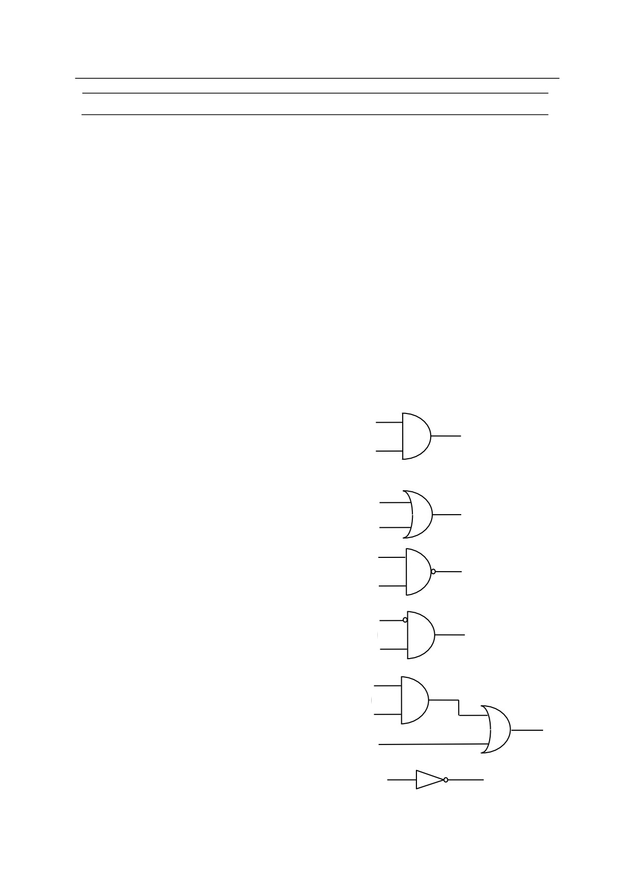
SOUT signal number䠙signal expression
Function
Outputs the specified signal when the specified condition is set.
Parameter
Signal number
Specifies the signal number of the signal to output. Only the signal numbers for output signals
can be specified. (1 to actual number of signals).
Signal expression
Specifies a signal number or a logical expression.
Explanation
This command is for logical calculation of signals. Logical expressions such as AND and OR
are used. The specified signal is output when that condition is set.
Example
1001
SOUT 1 = 1001 AND
1002
1
1002
1001
SOUT 1 = 1001 OR
1002
1
1002
1001
SOUT -1 = 1001 AND
1002
1
SOUT
1 = NOT(1001 AND
1002)
1002
1001
1
SOUT 1 = -1001 AND
1002
1002
1001
1002
SOUT 1 = (1001 AND
1002) OR
1003
1
1003
SOUT -1 = 1001 or SOUT
1= -1001 or
1001
1
SOUT 1 = NOT(1001)
5-105
5. Monitor Commands
STIM timer signal䠙input signal number, time
Function
Turns ON the timer signal if the specified input signal is ON for the given time.
Parameter
Timer signal
Selects the signal to turn ON. Acceptable signal numbers are from 3001 to 3064.
Input signal number
Specifies in whole numbers the input signal number or logical expression to monitor as a
condition for turning ON the timer signal. The value cannot exceed the number of signals
actually installed.
Time
Specifies in real numbers the time (sec) the input signal must be ON before turning ON the timer
signal.
Explanation
The monitored input signal has to be ON continuously in order for the timer signal to be turned
ON. If the input signal turns OFF before the given time passes, the time count restarts when that
signal turns ON again. If the input signal turns OFF, the timer signal turns OFF immediately.
However, the input signal affects the timer signal only when STIM is executed. Unless STIM is
executed, the timer signal remains ON even when the input signal turns OFF.
To check the state of signals 3001 to 3128, use the IO/E command.
Example
STIM 3001 = 1,5
sig2 turns ON if sig1 is ON for 5 seconds.
SOUT 2 = 3001
>PCEXECUTE
5-106
5. Monitor Commands
SETPICK
time1, time2, time3, time4, 䈈, time8
SETPLACE
time1, time2, time3, time4, 䈈, time8
Function
Sets the time to start clamp close control (SETPICK) or clamp open control (SETPLACE) for
each of the 8 clamps.
Parameter
Time 1 to 8
Sets the control time to open/close clamps 1 to 8 in seconds. Setting range: 0.0 to 10.0 seconds.
Explanation
See CLAMP instruction for more details.
5-107

5. Monitor Commands
HSENSESET no. = input signal number , output signal number,
signal output delay time
Option
Function
Declares the starting of signal detection to AS system. When this instruction is executed, AS
system starts to watch the sensor signal and accumulates the data such as pose, etc, into the buffer
memory at signal transaction. The data saved in the buffer memory can be read using HSENSE
instruction. Buffer memory can save up to 20 data.
Parameter
No.
Specifies the number for the monitoring results. Up to 2 input signals can be monitored.
Command for each signal is written as HSENSESET 1 or HSENSESET 2. Acceptable range is
1 or 2.
Input signal number
Set the signal number to monitor. Setting zero (0) terminates the monitoring.
Output signal number
Set the number of the signal to be output after system acquires the joint angle. The specified
signal turns ON for 0.2 seconds. This may be omitted.
Signal output delay time
Set the time to delay the output of signal after acquiring the pose data. Acceptable range is 0 to
9999 ms. This may be omitted.
[ NOTE ]
Even when the control power becomes OFF during watching, buffer memory
keeps the read data. It is possible to read the kept data by HSENSE
instruction after turning ON the control power again. However, watching
does not restart automatically, so HSENSESET should be executed again
Example
>HSENSESET 1 = wx_senser
Starts watching for input signal wx_senser.
5-108
5. Monitor Commands
HSENSE no. result variable, signal status variable, pose variable,
error variable, memory usage variable
Option
Function
Reads the data saved in the buffer memory by HSENSESET instruction.
Parameter
No.
Sets the monitoring number. To read data saved by HSENSESET 1, specify HSENSE1. To
read data saved by HSENSESET 2, specify HSENSE 2.
Result variable
Specifies the name of the real variable to which the watch result is assigned. After executing
HSENSE instruction, numerical value is assigned to this variable. Zero (0) is assigned to this
variable when AS system does not detect the signal transaction.
-1 is assigned to this variable
when AS system detects the signal transaction.
Signal status variable
Specifies the name of the real variable to which the status of signal transaction is assigned.
After executing HSENSE instruction, a numerical value is assigned to this variable. When the
signal(s) is turned from OFF to ON, ON (-1) is assigned. When the signal(s) is turned from ON
to OFF, OFF (0) is assigned to this variable.
Pose variable
Specifies the name of the pose variable to which the joint values at time of HSENSE signal input
are assigned.
Error variable
Specifies the name of the real variable to which the buffer overflow error result is assigned.
When no error occurs, 0 is assigned to this variable. When buffer memory overflows, a
numerical value (other than 0) is assigned to this variable. The buffer memory overflows after
accumulating data from more than 20 transactions.
Memory usage variable
Specifies the name of the real variable to which the number of used memory in the buffer is
assigned. The value assigned to this variable shows the number of memory in the buffer that is
already used. When only one memory is used, 0 will be assigned to the variable. When all the
memories are used, the value of the variable will be 19.
5-109
E Series Controller㻌 㻌 㻌 㻌 㻌 㻌 㻌 㻌 㻌 㻌 㻌 㻌 㻌 㻌 㻌 㻌 㻌 㻌 㻌 㻌 㻌 㻌 㻌 㻌 㻌 㻌
5. Monitor Commands
Kawasaki Robot AS Language Manual
5.8 MESSAGE DISPLAY COMMANDS
PRINT
Displays data.
TYPE
Displays data.
IFPWPRINT
Displays specified character string in a display window.
IFPWOVERWRITE
Displays by overwriting character string in a display
window.
IFPLABEL
Sets the labels for the icons on interface panel.
IFPTITLE
Sets the title for the specified page of the interface
panel.
IOBOARD_STATUS
Displays the mounting status of IO boards
SETOUTDA
Sets analog output environment. (Option)
OUTDA
Outputs voltage at set condition. (Option)
5-110
E Series Controller㻌 㻌 㻌 㻌 㻌 㻌 㻌 㻌 㻌 㻌 㻌 㻌 㻌 㻌 㻌 㻌 㻌 㻌 㻌 㻌 㻌 㻌 㻌 㻌 㻌 㻌
5. Monitor Commands
Kawasaki Robot AS Language Manual
PRINT device number: print data, …….
TYPE device number: print data, …….
Function
Displays on the terminal the print data specified in the parameter.
Parameter
Device number
Select the device for displaying the data:
0: All terminals that are connected
1: Personal computer
2: Teach pendant
3: - 5: Terminals connected via Ethernet
If not specified, the data is displayed on the currently selected device.
Print data
Select one or more from below. Separate the data with commas when specifying more than one.
(1) character string
e.g.
“count =”
(2) real value expressions (the value is calculated and displayed)
e.g.
count
(3) Format information (controls the format of the output message)
e.g.
/D, /S
A blank line is displayed if no parameter is specified.
Explanation
If “2” is entered for device number, the teach pendant screen changes automatically to keyboard
screen. Press <NEXT PAGE> to return to the regular screen.
The following codes are used to specify the output format of numeric expressions. The same
format is used until a different code is specified. In any format, if the value is too large to be
displayed in the given width, asterisks () will fill the space. In this case, change the number of
characters that can be displayed. The maximum number of characters displayed in one line is
128. To display more than 128 characters in a line, use the /S code explained on the following
page.
[ NOTE ]
If the MESSAGES switch is OFF, no message appears on the terminal screen.
5-111
E Series Controller㻌 㻌 㻌 㻌 㻌 㻌 㻌 㻌 㻌 㻌 㻌 㻌 㻌 㻌 㻌 㻌 㻌 㻌 㻌 㻌 㻌 㻌 㻌 㻌 㻌 㻌
5. Monitor Commands
Kawasaki Robot AS Language Manual
Format Specification Codes
/D
Uses the default format. This is the same as specifying the format as /G15.8
except that zeros following numeric values and all spaces but one between
numeric values are removed.
/Em.n
Displays the numeric values in scientific notation 䠄e.g. -1.234E+02䠅.
“m”
describes the total number of characters shown on the terminal and “n” the
number of decimal places.
“m” should be greater than n by five or more.
/Fm.n
Displays the numeric values in fixed point notation (e.g. -1.234).
“m” describes
the total number of characters shown on the terminal and “n” the number of
digits in the fraction part.
/Gm.n
If the value is greater than 0.01 and can be displayed in Fm.n format within m
digits, the value is displayed in that format. Otherwise, the value is displayed in
Gm.n format.
/Hn
Displays the values as a hexadecimal number in the n digit field.
/In
Displays the values as a decimal number in the n digit field.
The following parameters are used to insert certain characters between character strings.
/Cn
Inserts line feed n times in the place where this code is entered, either in front or
after the print data. If this code is placed within print data, n-1blank lines are
inserted.
/S
The line is not fed.
/Xn
Inserts n spaces.
/Jn
Displays the value as a hexadecimal number in the n digit field. Zeros are
displayed in place of blanks.
(Option)
/Kn
Displays the value as a decimal number in the n digit field. Zeros are displayed
in place of blanks.
(Option)
/L
This is the same as /D except that all the spaces are removed with this code.
(Option)
5-112
E Series Controller㻌 㻌 㻌 㻌 㻌 㻌 㻌 㻌 㻌 㻌 㻌 㻌 㻌 㻌 㻌 㻌 㻌 㻌 㻌 㻌 㻌 㻌 㻌 㻌 㻌 㻌
5. Monitor Commands
Kawasaki Robot AS Language Manual
Example
In this example the value of real variable “i” is 5, the fifth element of array variable “point” is
12.66666.
>PRINT "point", i, "=" , /F5.2, point [i]
point 5 = 12.67
㻌 㻌 㻌 㻌 㻌 The display should look like this.
point 5 =
If the value of point[5] is 1000 (1000.00), the display
should look like this. The value is too large to display (i.e.
the number of digits is greater than 5).
In the following example code /S is used to display the data without changing the lines after the
data.
>PRINT “ABC”
>PRINT/S, “DEF”
>PRINT “GHI”
ABC
DEFGHI
The display should look like this, with “GHI” displayed on
the same line as “DEF”.
5-113
E Series Controller㻌 㻌 㻌 㻌 㻌 㻌 㻌 㻌 㻌 㻌 㻌 㻌 㻌 㻌 㻌 㻌 㻌 㻌 㻌 㻌 㻌 㻌 㻌 㻌 㻌 㻌
5. Monitor Commands
Kawasaki Robot AS Language Manual
IFPWPRINT window number, row, column, background color, label color =
“character string”, “character string”, ……
Function
Displays the specified character string in the string window set by Auxiliary Function 0509
(Interface panel screen).
Parameter
Window number
Corresponds to the window number specified in Auxiliary Function 0509 as the window
specification used to display the string. Select from 1to 8 (standard).
Row
Specifies the row in the window for displaying the string. Acceptable number is from 1 to 4,
though it depends on the window size. If not specified, 1 is assumed.
Column
Specifies the column in the window for displaying the string. Acceptable number is from
1 to 70, though it depends on the window size. If not specified, 1 is assumed.
Background color
Selects the color of the background of the selected window. Acceptable numbers are from
0 to 15. If not specified, the background is white.
No.
Color
No.
Color
No.
Color
No.
Color
0
Grey
4
Green
8
Pink
12
Navy
1
Blue
5
Pale Blue
9
White
13
Reddish Brown
2
Red
6
Yellow
10
Black
14
Deep Green
3
Orange
7
White
11
Cyan
15
Lavender
Label color
Selects the color of the characters displayed. Acceptable numbers are from 0 to 15㻌 (See chart
above).㻌 If not specified, the characters are displayed in black.
Character string
Specifies the character string to display. All strings after the first string are displayed on the next
row starting at specified column. Execution of IFWPRINT clears all items, except the specified
character strings, from the specified window.
5-114
E Series Controller㻌 㻌 㻌 㻌 㻌 㻌 㻌 㻌 㻌 㻌 㻌 㻌 㻌 㻌 㻌 㻌 㻌 㻌 㻌 㻌 㻌 㻌 㻌 㻌 㻌 㻌
5. Monitor Commands
Kawasaki Robot AS Language Manual
Explanation
IFPWPRINT command can be used only when the interface panel is available for use. If the
parameters are not specified, the last setting of that particular window is selected (for first time
use, the above default values are set). If the character string does not fit in one row, its display
overflows to the next line (indenting to the selected column). Strings that extend beyond the
size of the window are not displayed. Control characters in the string are displayed as blanks.
5-115
E Series Controller㻌 㻌 㻌 㻌 㻌 㻌 㻌 㻌 㻌 㻌 㻌 㻌 㻌 㻌 㻌 㻌 㻌 㻌 㻌 㻌 㻌 㻌 㻌 㻌 㻌 㻌
5. Monitor Commands
Kawasaki Robot AS Language Manual
IFPWOVERWRITE window number, row, column, background color, label
color = “character string”, “character string”, ……
Function
Displays by overwriting the specified character string in the string window set by Auxiliary
Function 0509 (Interface panel screen).
Parameter
Window number
Corresponds to the window number specified in Auxiliary Function 0509 as the window
specification used to display the string. Select from 1to 8 (standard).
Row
Specifies the row in the window for displaying the string. Acceptable number is from 1 to 4,
though it depends on the window size. If not specified, 1 is assumed.
Column
Specifies the column in the window for displaying the string. Acceptable number is from
1 to 78, though it depends on the window size. If not specified, 1 is assumed.
Background color
Selects the color of the background of the selected window. Acceptable numbers are from
0 to 15. If not specified, the background is white.
No.
Color
No.
Color
No.
Color
No.
Color
0
Grey
4
Green
8
Pink
12
Navy
1
Blue
5
Pale Blue
9
White
13
Reddish Brown
2
Red
6
Yellow
10
Black
14
Deep Green
3
Orange
7
White
11
Cyan
15
Lavender
Label color
Selects the color of the characters displayed. Acceptable numbers are from 0 to 15㻌 (See chart
above).㻌 If not specified, the characters are displayed in black.
Character string
Specifies the character string to display. All strings after the first string are displayed on the next
row starting at specified column.
5-116
E Series Controller㻌 㻌 㻌 㻌 㻌 㻌 㻌 㻌 㻌 㻌 㻌 㻌 㻌 㻌 㻌 㻌 㻌 㻌 㻌 㻌 㻌 㻌 㻌 㻌 㻌 㻌
5. Monitor Commands
Kawasaki Robot AS Language Manual
Explanation
IFPWOVERWRITE command can be used only when the interface panel is available for use. If
the parameters are not specified, the last setting of that particular window is selected (for first
time use, the above default values are set). If the character string does not fit in one row, its
display overflows to the next line (indenting to the selected column). Strings that extend beyond
the size of the window are not displayed. Control characters in the string are displayed as blanks.
Unlike IFPWPRINT command/ instruction, the rows other than the row specified for display are
displayed unchanged as before executing IFPWOVERWRITE.
Example
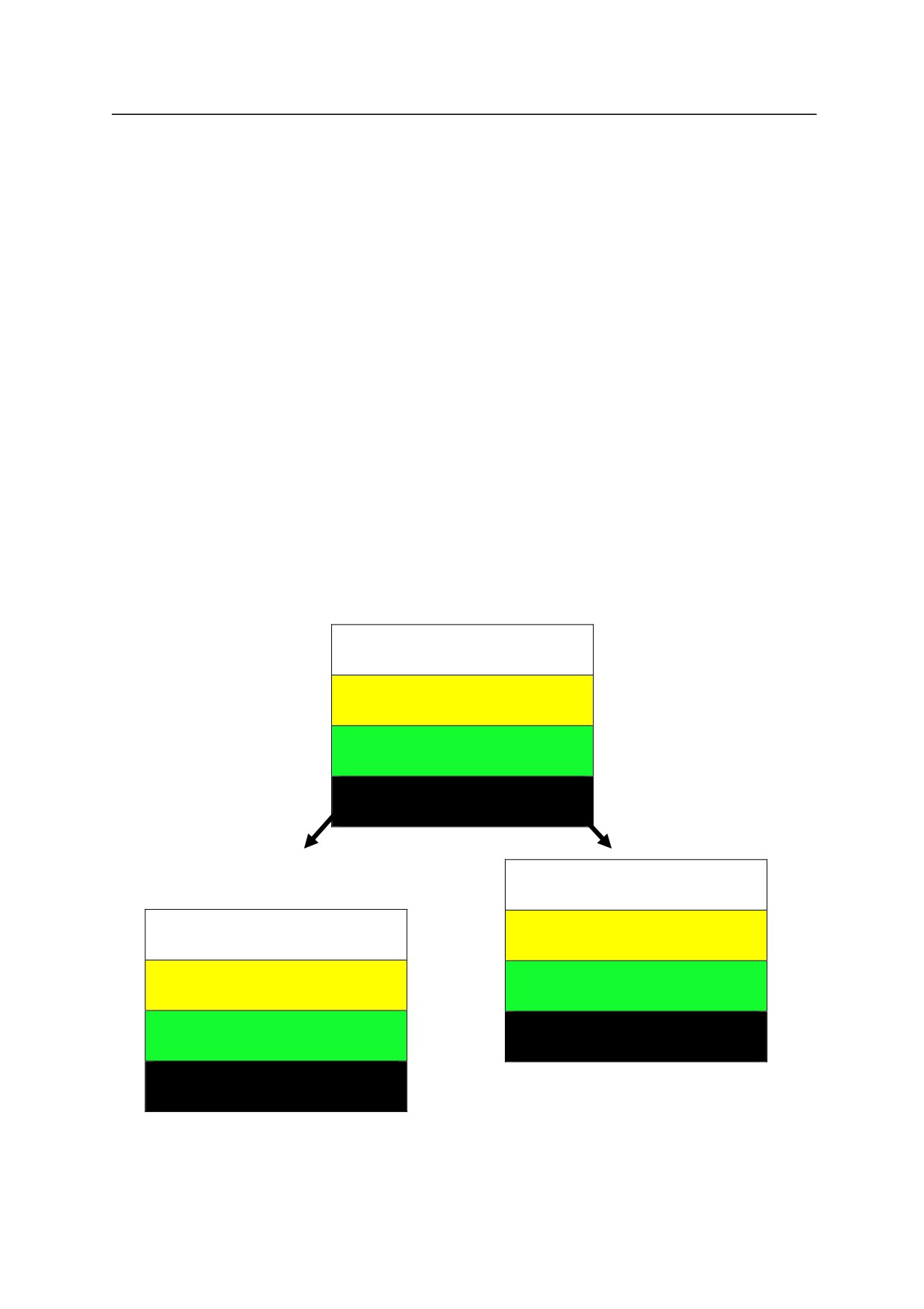
The figures below show the screens displayed when executing IFPWPRINT and
IFPWOVERWRITE command/ instruction from the screen showing “This is a pen”. The left
figure is the figure after executing ”IFPWPRINT 1,3,1,7,10=”my”. The characters on lines 1, 2,
and 4 disappear and line 3 shows ”my”. On the other hand, the right figure shows the screen
after executing “IFPWOVERWRITE 1,3,1,7,10=”my”. The characters on lines 1, 2, and 4 are
displayed as they were before executing the instruction and only line 3 has changed to ”my”.
This
is
a
pen
Displays
“This is a pen”
This
is
my
pen
my
Screen after executing
Screen after executing
IFPWPRINT 1,3,1,7,10 =“my”
IFPWOVERWRITE 1,3,1,7,10 =“my”
5-117
E Series Controller㻌 㻌 㻌 㻌 㻌 㻌 㻌 㻌 㻌 㻌 㻌 㻌 㻌 㻌 㻌 㻌 㻌 㻌 㻌 㻌 㻌 㻌 㻌 㻌 㻌 㻌
5. Monitor Commands
Kawasaki Robot AS Language Manual
IFPLABEL position, "label 1", "label 2", "label 3", "label 4"
㻌 㻌 㻌 㻌 㻌 㻌 㻌 㻌 㻌 㻌 㻌 㻌 㻌 㻌 㻌 㻌 㻌 㻌 㻌 㻌 㻌 㻌 㻌 㻌 㻌 㻌 㻌 㻌 㻌 㻌 㻌 㻌 㻌 㻌 㻌 㻌 㻌 㻌 㻌 㻌 㻌 㻌 㻌 㻌 㻌 㻌 㻌 㻌 㻌 㻌 㻌 㻌 㻌 㻌 㻌 㻌 㻌 㻌 㻌 㻌
Function
Sets and modifies the label of the icon at the specified position on the interface panel.
Parameter
Position
Specifies the display position on the interface panel of the icon to set/ modify the label.
Setting range: 1 - 112.
Displays
“This is a pen”
“Label 1”, “Label 2”…
Specifies the character string to display on the interface panel as the label of the specified icon.
Omitted label will not be changed.
Explanation
Sets and modifies the label for the icons displayed on the interface panel. When a position with
no icon set or when an icon with no label is specified, nothing occurs.
Example
>IFP
Screen after executing
Screen after executing
㻌
IFPWPRINT 1,3,1,7,10 =“my”
IFPWOVERWRITE 1,3,1,7,10 =“my”
Icon at position 10 on the interface panel is changed to “label 3” (label 1, label 2 is not changed
because the parameters are omitted.)
㻌
㻌
㻌
㻌
㻌
㻌
㻌
㻌
㻌
㻌
㻌
㻌
㻌
㻌
㻌
5-118
E Series Controller㻌 㻌 㻌 㻌 㻌 㻌 㻌 㻌 㻌 㻌 㻌 㻌 㻌 㻌 㻌 㻌 㻌 㻌 㻌 㻌 㻌 㻌 㻌 㻌 㻌 㻌
5. Monitor Commands
Kawasaki Robot AS Language Manual
㻌
IFPTITLE page no., "title"
㻌 㻌 㻌 㻌 㻌 㻌 㻌 㻌 㻌 㻌 㻌 㻌 㻌 㻌 㻌 㻌 㻌 㻌 㻌 㻌 㻌 㻌 㻌 㻌 㻌 㻌 㻌 㻌 㻌 㻌 㻌 㻌 㻌 㻌 㻌 㻌 㻌 㻌 㻌 㻌 㻌 㻌 㻌 㻌 㻌 㻌 㻌 㻌 㻌 㻌 㻌 㻌 㻌 㻌 㻌 㻌 㻌 㻌 㻌 㻌
Function
Sets and modifies the title for the specified page of the interface panel.
Parameter㻌
Page no.
Specifies the page of the interface panel to change the title. Setting range: 1- 4.
“Title”
Specifies the character string to display on the page as the title. Default setting is “Interface
Panel”. When NULL string (“”) is specified, this default setting is also displayed.
㻌
Explanation
Sets and modifies the title for the specified page of the interface panel.
㻌
Example
>IFPTITLE 1, "Page 1"
The title of the first page of the interface
panel is changed to “Page 1”.
㻌
>IFPTITLE 2, ""
The title of the second page of the
interface panel is changed to “Interface
Panel”.㻌
㻌
㻌
㻌
㻌
㻌
5-119
E Series Controller㻌 㻌 㻌 㻌 㻌 㻌 㻌 㻌 㻌 㻌 㻌 㻌 㻌 㻌 㻌 㻌 㻌 㻌 㻌 㻌 㻌 㻌 㻌 㻌 㻌 㻌
5. Monitor Commands
Kawasaki Robot AS Language Manual
IOBOARD_STATUS
Function
Displays the installation status of IO board when IOBOARD_STATUS command is executed.
Explanation
Displays the correspondence between IO board address and IO signal number/ analog output
channel number. When using 1TW and 1UR board at the same time, use this command to
confirm the correspondence between each board and the signal numbers.
Example
>IOBOARD_STATUS<ret>
IO
1- 16
17- 32
33- 48
49- 64
65- 80
81- 96
97-112
113-128
1TWn
1TWn
1URn
1URn
1TWn
1TWn NON NON
DA
1- 4
5-
8
9- 12
13- 16
1TWn
1URn NON NON
Title䠖 IO indicates the signal numbers, DA indicates the channel numbers
1TWn: Corresponds to 1TW board (32 signals)
1URn: Corresponds to 1UR board (16 signals)
NON : Not used
n 䠖 Board address for each aboard (1 to 4)
If the board addresses for 1TW board and 1UR board are set to the first and third boards
respectively, the following signal numbers are used.
>IOBOARD_STATUS<ret>
IO
1- 16
17- 32
33- 48
49- 64
65- 80
81- 96
97-112
113-128
1TW1
1TW1
1UR3 NON NON
NON NON NON
DA
1- 4
5-
8
9- 12
13- 16
1TW1
1UR3 NON
NON
At this time, if 1UR board is set as the second board, signal numbers 17-32 duplicate with 1TW
board so error (D2056) 䇾[I/O board(No.XX)]Several boards have same ID address.” occurs.
5-120
E Series Controller㻌 㻌 㻌 㻌 㻌 㻌 㻌 㻌 㻌 㻌 㻌 㻌 㻌 㻌 㻌 㻌 㻌 㻌 㻌 㻌 㻌 㻌 㻌 㻌 㻌 㻌
5. Monitor Commands
Kawasaki Robot AS Language Manual
SETOUTDA port No. = LSB, No. of bits, logic, max. voltage, min. voltage
㻌 㻌 㻌 㻌 㻌 㻌 㻌 㻌 㻌 㻌 㻌 㻌 㻌 㻌 㻌 㻌 㻌 㻌 㻌 㻌 㻌 㻌 㻌 㻌 㻌 㻌 㻌 㻌 㻌
Option
Function
Specifies the analog output environment including: port number and LSB, number of bits and
logic voltage for signal output, maximum and minimum voltage.
Parameter
Port No.
Specifies port number. Setting range: integer between 1 and 16.
LSB
Specifies as an integer the first signal number to be output for D/A conversion. Setting range:
OUT 1- OUT 125, 2001 - 2125, 3000 (1st channel of 1TW), 3001 (2nd channel of 1TW), hereafter
increment by one up to the number of DA channels of 1TW board. Default value is 3000.
Previous setting remains in effect if not specified.
Number of bits
Specifies the integer number of bits output for each signal to be D/A converted. Setting range: 4
bits - 16 bits. Set to 12 bits when specifying 3000 - [3000 + number of DA channel on 1TW
board] for parameter LSB above. Default value is 8 bits. Previous setting remains in effect if
not specified.
Logic
Sets output data either to positive logic (1) or negative logic (0). Initial set value is 0 (negative
logic). Previous setting remains in effect if not specified. Set the logic to positive for 1TW.
Maximum voltage
Specifies the maximum voltage of hardware (D/A output). Setting range: -15 - +15V. Unit: V.
Default value is 13V. Round off to first decimal place. Previous setting remains in effect if
not specified.
Minimum voltage
Specifies the minimum voltage of hardware (D/A output). Setting range: -15 - +15V. Unit: V.
Default value is 0V. Round off to first decimal place. Previous setting remains in effect if not
specified.
See also 6.8 SETOUTDA, OUTDA instructions.
5-121
E Series Controller㻌 㻌 㻌 㻌 㻌 㻌 㻌 㻌 㻌 㻌 㻌 㻌 㻌 㻌 㻌 㻌 㻌 㻌 㻌 㻌 㻌 㻌 㻌 㻌 㻌 㻌
5. Monitor Commands
Kawasaki Robot AS Language Manual
[ NOTE ]
1. Actual voltage output depends on the hardware used.
2. Error occurs if the value for maximum voltage is set lower than the minimum
voltage.
5-122
E Series Controller㻌 㻌 㻌 㻌 㻌 㻌 㻌 㻌 㻌 㻌 㻌 㻌 㻌 㻌 㻌 㻌 㻌 㻌 㻌 㻌 㻌 㻌 㻌 㻌 㻌 㻌
5. Monitor Commands
Kawasaki Robot AS Language Manual
OUTDA㻌 㻌 voltage, port number
㻌 㻌 㻌 㻌 㻌 㻌 㻌 㻌 㻌 㻌 㻌 㻌 㻌 㻌 㻌 㻌 㻌 㻌 㻌 㻌 㻌 㻌 㻌 㻌 㻌 㻌 㻌 㻌 㻌 㻌 㻌 㻌 㻌 㻌 㻌 㻌 㻌 㻌 㻌 㻌 㻌 㻌 㻌 㻌 㻌 㻌 㻌 㻌 㻌 㻌 㻌 㻌 㻌 㻌 㻌 㻌 㻌 㻌 㻌 㻌 Option㻌
Function
Outputs the voltage according to the condition set to the specified port.
Parameter
Voltage
Specifies the voltage to be output from D/A port. Setting range: -15 - +15 V. Unit: 0.1 V.
Round off to first decimal place.
㻌
Port number
Sets the port number. Setting range: integer between 1 and 16. If not specified, 1 is assumed.
[ NOTE ]
Confirm that command voltage and actual output voltage are the same by setting
output environment to correspond with the hardware settings via SETOUTDA
instruction (command).
5-123
E Series Controller㻌 㻌 㻌 㻌 㻌 㻌 㻌 㻌 㻌 㻌 㻌 㻌 㻌 㻌 㻌 㻌 㻌 㻌 㻌 㻌 㻌 㻌 㻌 㻌 㻌 㻌
5. Monitor Commands
Kawasaki Robot AS Language Manual
5-124
6. Program Instructions
6.0 PROGRAM INSTRUCTIONS
This chapter groups the program instructions in the following categories, and
describes each instruction in detail. A program instruction consists of a keyword
expressing the instruction and parameter(s) following that key word, as shown in
the example below.
Example
Keyword Parameter
JMOVE pose variable, clamp number
Parameters marked with
can be omitted.
Always enter a space between the keyword and the parameter.
in the examples represent the
Enter
key.
6-1
6. Program Instructions
6.1 MOTION INSTRUCTIONS
JMOVE
Moves robot in joint interpolated motion.
LMOVE
Moves robot in linear interpolated motion.
DELAY
Stops robot motion for specified time.
STABLE
Stops robot motion for specified time after the axes coincide.
JAPPRO
Approach the destination in joint interpolated motion.
LAPPRO
Approach the destination in linear interpolated motion.
JDEPART
Leaves the current pose in joint interpolated motion.
LDEPART
Leaves the current pose in linear interpolated motion.
HOME
Moves to the home pose.
DRIVE
Moves in the direction of a single axis.
DRAW
Moves the specified amount in the direction of the X, Y, Z, axis of the
base coordinates.
TDRAW
Moves the specified amount in the direction of the X, Y, Z, axis of the
tool coordinates.
ALIGN
Aligns the tool Z axis with the base coordinate axis.
HMOVE
Moves in linear interpolated motion (the wrist joint moves in joint
interpolated motion.)
XMOVE
Moves in linear movement to the specified pose.
C1MOVE
Moves in circular interpolated motion. (Option)
C2MOVE
Moves in circular interpolated motion.
(Option)
6-2
6. Program Instructions
JMOVE pose variable, clamp number
LMOVE pose variable, clamp number
Function
Moves the robot to the specified pose.
JMOVE: Moves in joint interpolated motion.
LMOVE: Moves in linear interpolated motion.
Parameter
Pose variable
Specifies the destination pose of the robot.
(Can be in transformation values, compound
transformation values, joint displacement values or pose information functions.)
Clamp number
Specifies the clamp number to open or close at the destination pose. Positive number closes the
clamp, and negative number opens it. Any clamp number can be set, up to the maximum
number set via HSETCLAMP command (or auxiliary function 0605). If omitted, the clamp
does not open or close.
Explanation
The robot moves in joint interpolated motion when JMOVE instruction is executed. The robot
moves so that the ratios of distance traveled to the total distance are equal at all joints throughout
the movement from the starting pose to the end pose.
The robot moves in linear interpolated motion when LMOVE instruction is executed. The
origin of the tool coordinates (TCP) moves along a linear trajectory.
Example
JMOVE
#pick
Moves to pose described by joint displacement values “#pick” in joint
interpolated motion.
LMOVE ref+place
Moves to the pose described by the compound transformation values
“ref + place” in linear interpolated motion.
LMOVE
#pick,1
Moves to the pose described by joint displacement values “#pick” in
linear interpolated motion. Upon reaching the pose, clamp 1 is closed.
6-3
6. Program Instructions
DELAY time
Function
Stops the robot motion for the specified time.
Parameter
Time
Specifies in seconds for how long the robot motion is stopped.
Explanation
In AS system, DELAY instruction is considered as a motion instruction that “moves to nowhere”.
Even if the robot motion is stopped by DELAY instruction, all the program steps before the next
motion instruction are executed before stopping.
Example
DELAY 2.5
Stops the robot motion for 2.5 seconds.
STABLE time
Function
Postpones execution of next motion instruction until the specified time elapses after the axes
coincide.
(Waits until the robot is stable.)
Parameter
Time
Specifies in seconds for how long the robot motion is kept stable.
Explanation
If coincidence of the axes fails while the robot is stopped by this command, the time is counted
from when the axes coincide again.
6-4
6. Program Instructions
JAPPRO pose variable , distance
LAPPRO pose variable , distance
Function
Moves in tool Z direction to a specified distance from the taught pose.
JAPPRO: Moves in joint interpolated motion.
LAPPRO: Moves in linear interpolated motion.
Parameter
Pose variable
Specifies the end pose (in transformation values or joint displacement values)
Distance
Specifies the offset distance between the end pose and the pose the robot actually reaches on the
Z axis direction of the tool coordinates (in millimeters). If the specified distance is a positive
value, the robot moves towards the negative direction of the Z axis. If the specified distance is a
negative value, the robot moves towards the positive direction of the Z axis.
Explanation
In these commands, tool orientation is set at the orientation of the specified pose, and the position
is set at the specified distance away from the specified pose in the direction of the Z axis of the
tool coordinates.
Example
JAPPRO place,100
Moves in joint interpolated motion to a pose 100 mm away from the
pose “place” in the direction of the Z axis of the tool coordinates.
Pose “place” is described in transformation values.
LAPPRO place, offset
Moves in linear interpolated motion to a pose away from the pose
“place”, described in transformation values, at the distance defined by
the variable “offset” in the direction of the Z axis of the tool
coordinates.
6-5
6. Program Instructions
JDEPART distance
LDEPART distance
Function
Moves the robot to a pose at a specified distance away from the current pose along the Z axis of
the tool coordinates.
JDEPART : Moves in joint interpolated motions.
LDEPART : Moves in linear interpolated motions.
Parameter
Distance
Specifies the distance in millimeters between the current pose and the destination pose along the
Z axis of the tool coordinates. If the specified distance is a positive value, the robot moves
“back” or towards the negative direction of the Z axis. If the specified distance is a negative
value, the robot moves “forward” or towards the positive direction of the Z axis.
Example
JDEPART
80
The robot tool moves back 80 mm in Z direction of the tool coordinates
in joint interpolated motion.
LDEPART
2offset
The robot tool moves back 2offset (200 mm if offset = 100) in Z
direction of the tool coordinates in linear interpolated motion.
6-6
6. Program Instructions
HOME home pose number
Function
Moves in joint interpolated motion to pose defined as HOME or HOME2.
Parameter
Home pose number
Specifies the home pose number (1 or 2). If omitted, HOME 1 is selected.
Explanation
Two home poses can be set (HOME 1 and HOME 2). This instruction moves the robot to one
of the home poses in joint interpolated motion. The home pose should be defined beforehand
using the SETHOME or SET2HOME command/ instruction. If the home pose is not defined,
the null origin (all joints at 0) is assumed as the home pose.
Example
HOME
Moves to the home pose defined by SETHOME command/
instruction in joint interpolated motion.
HOME 2
Moves to the home pose defined by SET2HOME command/
instruction in joint interpolated motion.
6-7
6. Program Instructions
DRIVE joint number, displacement, speed
Function
Moves a single joint of the robot.
Parameter
Joint number
Specifies the joint number to move. (In a six-joint robot, the joints are numbered 1 to 6, starting
from the joint furthest from the tool mounting flange.)
Displacement
Specifies the amount to move the joint, as either a positive or negative value.
The unit for this value is the same as the value that describes the pose of the joint; i.e. if the joint
is a rotational joint, the value is expressed in degrees (), and if the joint is a slide joint, the value
is expressed in distance (mm).
Speed
Specifies the speed for this motion. As in regular program speed, it is expressed as a percentage
of the monitor speed. If not specified, 100㻌 % of the monitor speed is assumed.
Explanation
This instruction moves only one specified joint.
The motion speed for this instruction is combination of the speed specified in this instruction and
the monitor speed. The program speed set in the program does not affect this instruction.
Example
DRIVE
2,-10,75
Moves joint 2 (JT2) 10 from the current pose. The speed is 75 %㻌
of the monitor speed.
6-8