Kawasaki Robot Controller E Series. Reference Manual (2015) - page 5

5. Monitor Commands
CONTINUE NEXT
Function
Resumes execution of a program stopped by PAUSE instruction, ABORT or HOLD command,
or as a result of an error. This command can also be used to start programs made ready to
execute by PRIME, STEP or MSTEP command.
Parameter
NEXT
If NEXT is not entered, execution resumes from the step at which execution stopped. If it is
entered, execution resumes from the step following the step at which execution stopped.
Explanation
The effect that keyword NEXT has on restart of the program differs depending on how the
program was stopped.
1. Program stopped during execution of a step or of a motion:
CONTINUE restarts the program and re-executes the interrupted step.
CONTINUE NEXT restarts at the step after the step where program stopped.
2. Program execution is stopped after a step or a motion is completed:
CONTINUE and CONTINUE NEXT restarts program from the step immediately after the
completed step, regardless of NEXT.
3. Program suspended by a WAIT, SWAIT or TWAIT instruction:
CONTINUE NEXT skips the above instructions and resumes execution from the next step.
[ NOTE ]
The CONTINUE command cannot resume the program execution when:
The program ended properly
The program was stopped using the HALT instruction
The KILL command was used
When the program is executed by CONTINUE command, the last step is displayed when the
program is completed normally. On the other hand, the first step of the program is displayed
when the program completes normally by
A +
CYCLE START.
5-43
5. Monitor Commands
STPNEXT
Function
Executes the next step when the system switch STP_ONCE is ON.
Explanation
When the system switch STP_ONCE is ON, the program can be executed in one step increment.
This command advances the execution to the next step in the program.
KILL
Function
Initializes the stack of the robot program.
Explanation
If the program is stopped by PAUSE instruction, ABORT command, or an error, the program
stack is kept at the current status. The KILL command is used to initialize the stack. Once the
KILL command is used, the CONTINUE command is ineffective, since there is no program on
the stack.
5-44
5. Monitor Commands
DO program instruction
Function
Executes a single program instruction. (Some program instructions cannot be used with this
command.)
Parameter
Program instruction
Executes the specified program instruction. If omitted, the program instruction last executed
using the DO command is executed again.
Explanation
Program instructions are typically written within the programs and executed as program steps.
However the DO command enables execution of a single instruction without having to create a
program to run that instruction.
The robot moves in speed equivalent to monitor speed 10 % when operated by DO command.
When the monitor speed is set below 10%, then the robot moves at that set monitor speed.
Example
>DO JMOVE safe
The robot moves to the pose “safe” in joint interpolation
motion.
>DO HOME
The robot moves to the home pose in joint interpolation
motion.
5-45
5. Monitor Commands
5.5 POSE INFORMATION COMMANDS
HERE
Assigns the current pose to the specified variable.
POINT
Defines a pose variable.
POINT/X
Sets the X value of a transformation value variable.
POINT/Y
Sets the Y value of a transformation value variable.
POINT/Z
Sets the Z value of a transformation value variable.
POINT/OAT
Sets the OAT values of a transformation value variable.
POINT/O
Sets the O value of a transformation value variable.
POINT/A
Sets the A value of a transformation value variable.
POINT/T
Sets the T value of a transformation value variable.
POINT/7
Sets the seventh axis value for a transformation value variable.
POINT/18
Sets JT18 value of a transformation value variable.
POINT/EXT
Sets the external axis (JT7 - JT18) value of a transformation
value variable.
5-46
5. Monitor Commands
HERE pose variable
Function
Assigns the current pose to the pose variable with the specified variable name. The pose may be
expressed in transformation values, joint displacement values or compound transformation
values.
Parameter
Pose variable
Variable value can be specified in transformation values, joint displacement values, or compound
transformation values.
Explanation
The pose may be expressed in transformation values, joint displacement values or compound
transformation values.
[ NOTE ]
Only the right most variable in the compound transformation values is
defined. (See example below). If the other variables used in the compound
values are not defined, this command results in an error.
The values of the variable are displayed on the terminal followed by the message “Change?”
The values can be changed by entering the values separating each value with a comma. The
value that is not changed may be skipped. Press
after the message “Change?” to finish editing
the values.
If the variable is defined in joint displacement values (variable name starting with #), the joint
values of the current pose are displayed. If the variable is transformation values, the XYZOAT
values are displayed. The XYZ values describe the position of the origin of the tool coordinates
with respect to the base coordinates. The OAT values describe the orientation of the tool
coordinates.
Example
>HERE
#pick
Assigns the robot’s current pose to variable “#pick” (joint
displacement values)
>HERE place
Assigns the robot’s current pose to variable “place”
(transformation values)
HERE plate+object
Pose “object ” is defined so that its relative pose to the pose
“plate” becomes the robot’s current pose. Error occurs if
“plate ” is undefined.
5-47
5. Monitor Commands
POINT pose variable 1䠙pose variable 2, joint displacement value variable
Function㻌
Assigns the pose information on the right of “=” to the pose variable on the left side of “=”.
Parameter㻌
Pose variable 1
Specifies the name of pose variable to be defined by joint displacement values, transformation
values, or compound transformation values.
Pose variable 2
If not specified, the “=” sign is also omitted.
Joint displacement value variable
Specifies a variable defined by joint displacement values. This parameter must be set if the pose
variable values on the left are in joint displacement values and the pose variable values on the
right are in transformation values (if the parameter on the left is not in joint displacement values,
this parameter cannot be set). The joint displacement values specified here expresses the
configuration of the robot at the pose. If not specified, the current configuration is used to define
the pose variable.
Explanation㻌
Assigns pose values specified by the parameter on the right to the pose variable specified as pose
variable 1. When pose variable 2 is not specified, any value already defined for pose variable 1
is displayed on the terminal, and can be edited. If pose variable 1 is undefined, the values
displayed will be 0, 0, 0, 0, 0, 0.
Once POINT is executed, the pose values appear followed by the message “Change?” and a
prompt. The values can then be edited. Exit by pressing only
at the prompt.
If pose variable 1 is defined by joint displacement values, joint values appear on the display. If
the variable is specified by transformation values, the XYZOAT values are displayed. The XYZ
values describe the position of the origin of the tool coordinates with respect to the base
coordinates. The OAT values describe the orientation of the tool coordinates. When the
variable is expressed in compound transformation values, the right most variable in the compound
transformation value is defined. If the other variables used in the compound value are not
defined, this command results in error.
5-48
5. Monitor Commands
[ NOTE ]
When value types on the right and the left side of ”=” differ, this command works as follows:
1.
POINT transformation values=joint displacement values
㻌
The joint displacement values on the right are transformed into transformation values and
assigned to pose variable 1 on the left.
2.
POINT joint displacement values=transformation values, joint displacement values
The transformation values on the right are transformed into joint displacement values and
assigned to pose variable 1 on the left. If pose variable 3 is specified, the transformation
value of pose variable 2 is transformed with the robot taking the configuration determined
by the specified joint displacement values. If not specified, the transformation value is
transformed with the robot in its current configuration.
When specifying values, maximum of nine decimal digits can be entered. The accuracy of
entries with more than nine digits cannot be guaranteed.
Example
>POINT
#park
Displays the values of joint displacement value
variable “#park”.㻌 (0,0,0,0,0,0 is displayed if it is
undefined)
JT1
JT2
JT3
JT4
JT5
JT6
10.000
15.000
20.000
30.000
50.000
40.000
Change?(If not, hit RETURN only)
>,,,-15
JT1
JT2
JT3
JT4
JT5
JT6
10.000
15.000
20.000
-15.000
50.000
40.000
Change?(If not, hit RETURN only)
>
>POINT pick1=pick
㻌 㻌 㻌 㻌 Assigns the transformation values of “pick” as
transformation values of “pick1” and displays the
values for correction.
>POINT pos0=#pos0
Transforms the joint displacement values of variable
#pos0 into transformation values and assigns them to
variable “pos0”.
>POINT
#pos1=pos1,#pos2
Transforms the transformation values of variable
“pos1” into joint displacement values using the
robot configuration given by variable #pos2 and
assigns the values to variable #pos1.
5-49
5. Monitor Commands
POINT/ X transformation value variable 1= transformation value variable 2
POINT/ Y transformation value variable 1= transformation value variable 2
POINT/ Z transformation value variable 1= transformation value variable 2
POINT/ OAT transformation value variable 1= transformation value variable 2
POINT/ O transformation value variable 1= transformation value variable 2
POINT / A transformation value variable 1= transformation value variable 2
POINT / T transformation value variable 1= transformation value variable 2
POINT/ 7 transformation value variable 1= transformation value variable 2
䞉㻌
䞉㻌
䞉㻌
POINT/ 18 transformation value variable 1= transformation value variable 2
POINT/ EXT transformation value variable 1= transformation value variable 2
Function㻌
Assigns the components of the transformation values of pose variable 2 to the corresponding
components of the transformation values of pose variable 1. The values will be displayed on the
terminal for editing.
Parameter
Transformation value variable 1
Specifies the variable to be defined by transformation values. (variable defined by transformation
values or compound transformation values)
Transformation value variable 2
If not specified, the “=” sign can be also omitted.
Explanation㻌
Assigns only the specified components (X, Y, Z, O, A, T, 7 - 18th axes, all external axes) of the
transformation values. Once this command is executed, the values of each component are
displayed followed by the message “Change?” and a prompt. These values can then be edited.
Exit by pressing only
key at the prompt.
Example
The following command assigns the OAT values of a1 to a2. The transformation values of a1
and a2 are as below:
a1 = (1000, 2000, 3000, 10, 15, 30) , a2 = undefined
>POINT/OAT a2 = a1
X[mm] Y[mm] Z[mm] O[deg] A[deg] T[deg]
0.
0.
0.
10.
15.
30.
Change? (If not, hit RETURN only)
>
5-50
5. Monitor Commands
5.6 SYSTEM CONTROL COMMANDS
㻌
STATUS
Displays system status.
WHERE
Displays the current pose data for the robot.
IO
Displays the status of the binary signals.
FREE
Displays amount of free memory.
TIME
Displays and sets the current time and date.
ULIMIT
Sets the upper limit of the robot motion.
LLIMIT
Sets the lower limit of the robot motion.
BASE
Changes the base transformation values.
TOOL
Defines the tool transformation values.
SET_TOOLSHAPE
Sets tool shape data.
ENA_TOOLSHAPE
Enables/ disables speed control by tool shape.
TOOLSHAPE
Sets data for speed control by tool shape.
SETHOME
Sets the home pose.
SET2HOME
Sets the home pose no.2.
ERRLOG
Displays a history of error conditions.
OPLOG
Displays a history of operations.
SWITCH
Displays the system switch setting.
ON
Enable the system switch.
OFF
Disables the system switch.
ZSIGSPEC
Sets and displays the total number of I/O signals.
HSETCLAMP
Sets the default clamp specifications.
DEFSIG
Displays or sets software dedicated signals.
ZZERO
Displays or sets the zeroing data.
ERESET
Resets the error condition.
SYSINIT
Initializes the entire system.
HELP
Displays a listing of AS language commands/instructions.
ID
Displays the version information of the software.
WEIGHT
Sets the weight load data.
5-51
5. Monitor Commands
ENCCHK_ EMG
Sets an acceptable deviation range when checking the robot’s
pose at an emergency stop versus the pose when the robot is
restart.
ENCCHK_ PON
Sets the acceptable range for the difference in encoder value
when the control power is turned ON versus the value when the
power was turned OFF the last time.
SLOW_ REPEAT
Sets slow repeat mode speed.
REC_ ACCEPT
Enables/disables recording and or changing programs.
ENV_ DATA
Sets auto servo off timer and teach pendant connect/
disconnect.
ENV_ 2DATA
Sets terminal connect/disconnect.
CHSUM
Clears check sum error.
TPLIGHT
Turns on teach pendant backlight.
IPEAKLOG
Displays peak current values. (Option)
IPEAKCLR
Resets peak current values. (Option)
OPEINFO
Displays operation information.
OPEINFOCLR
Clears operation information.
REFFLTSET_STATUS
Displays values for moving average span of the command
values.
FFSET_STATUS
Displays of robot speed/ acceleration speed feed forward gain.
5-52
5. Monitor Commands
STATUS
㻌
Function㻌
Displays the status of the system and the current robot program.
Explanation㻌
The system and the robot program status are displayed in the following format:
1.…
Robot status:
REPEAT mode:
2.…
Environment:
Monitor Speed(%) = 10.0
Program Speed(%)ALWAYS = 100.0
ALWAYS Accu.[mm]䠙
1.0
3.…
Stepper status: Program is not running.
4.…
Execution cycles
Completed cycles:
3
Remaining cycles䠖 Infinite
5.…
Program name
Prio
Step number
test
0
1
WAIT sig(1001)
1. Robot status
The current robot status is one of the following:
Error state:
An error has occurred; try the error reset operation.
Motor power off:
Motor power is OFF.
Teach mode:
Motor power is ON; the robot is controlled using the teach pendant.
Repeat mode:
Motor power is ON; the robot is controlled by the robot program.
Repeat mode cycle start ON: Motor power is ON; the robot program is running.
Program waiting:
Motor power is ON; the robot program is running and in wait condition
(executing a WAIT, SWAIT, or TWAIT instruction).㻌
2. Environment㻌
The current monitor speed (in percentages)
3. Stepper status
The current status of step execution.
4. Execution cycles
Completed cycles:
Execution cycles already completed(0 to 32767)
Remaining cycles:
Remaining execution cycles. If a negative number was specified for
execution cycles in the EXECUTE command, “infinite” is displayed.
5. Program name
The name of the program or step currently being executed or in wait condition.
5-53
5. Monitor Commands
WHERE display mode
Function㻌
Displays the current robot pose.
Parameter㻌
Display mode
Selects the mode in which the data is displayed. There are 16 modes as shown below (modes 7
to 16 are options). If the mode is not specified, transformation values of the TCP in the base
coordinates and the joint angles (JT1,㻌 JT2, …, JT3) are displayed. The display mode does not
change until
is pressed again.
WHERE
…… Displays the current robot pose in transformation values in the base
coordinates and the joint angles.
WHERE
1
…… Displays the current pose by joint angles (deg).
WHERE
2
…… Displays the current pose in XYZOAT in the base coordinates (mm, deg).
WHERE
3
…… Displays the current command values (deg).
WHERE
4
…… Displays deviations from the command values (bit).
WHERE
5
…… Displays encoder values of each joint (bit).
WHERE
6
…… Displays speed of each joint (deg/s).
WHERE
7
…… Displays the current pose including the external axis. (Option)
WHERE
8
…… Displays current pose in the fixed workpiece coordinates.
(Option)
WHERE
9
…… Displays the instructed value of each joint for transformation values.
WHERE
10
……Displays the motor current.
WHERE
11
……Displays the motor speed.
WHERE
12
……Displays the current transformation values expressed in base coordinates of
another robot. (Option)
WHERE
13
……Displays the current transformation values expressed in tool coordinates of
another robot. (Option)
WHERE
14
……Displays the instructed value of the motor current.
WHERE
15
……Displays the original data of the encoder.
WHERE
16
……Displays the speed of TCP.
WHERE
35
䈈䈈Displays the motor load arrival rate (%) for each joint
WHERE
43
䈈䈈Displays the encoder temperature (ºC) for each joint
5-54
5. Monitor Commands
Example
>WHERE
JT1
JT2
JT3
JT4
JT5
JT6
9.999
0.000
0.000
0.000
0.000
0.000
X[mm] Y[mm] Z[mm] O[deg] A[deg] T[deg]
15.627
88.633
930.000
-9.999
0.000
0.000
5-55
5. Monitor Commands
IO/E signal number
Function㻌
Displays the current status of all the external and internal I/O signals.
Parameter㻌
Signal number
1………Displays 132, 10011032, 20012032
2………Displays 3364, 10331064, 20332064
3………Displays 6596, 10651096, 20652096
4………Displays 97128, 10971128, 20972128
If not specified……Displays 132, 10011032, 20012032
Explanation㻌
If the system switch DISPIO_01 is OFF, “o” will be displayed for signals that are ON, “x” is for
signals that are OFF. Dedicated signals are displayed in uppercase letters (“O” and “X”). If
the system switch DISPIO_01 is ON, “1” is displayed for signals that are ON and “0” for those
that are OFF.
“-” is displayed for external I/O signals that are not installed.
If “/E” is entered with the command, signal numbers 3001 and above are displayed along with the
signals numbered 1, 1001, 2001.
(Option)
The display updates continuously until the display is terminated with the
key.
(See 7.0 DISPIO_01㻌 system switch)
Example㻌
When DISPIO_01 is OFF
>IO
32 -
1
xxxx xxxx xxxx xxxx xxxx xxxx xxxo xxxo
1032 - 1001 xxxx xxxx xxxx xxxx xxxx xxxx xxxx oxxx
2032 - 2001 xxxx xxxx xxxx xxxx xxxx xxxx xxxx xxxx
>
5-56
5. Monitor Commands
>IO/E
32 -
1
xxxx xxxx xxxx xxXX xxxx XXXX XXXO XXXO
1032 - 1001 xxxx xxxx xxxx xxXX xxxx XXXX XXXO XXXO
2032 - 2001 xxxx xxxx xxxx xxxx
xxxx xxxx xxxx
xxxx
3032 - 3001 xxxx xxxx xxxx xxxx
xxxx xxxx xxxx
xxxx
>
When DISPIO_01 is ON
>IO
32 -
1
0000
0000
0000
0000
0000
0000
0001
0001
1032 - 1001
0000
0000
0000
0000
0000
0000
0000
1000
2032 - 2001
0000
0000
0000
0000
0000
0000
0000
0000
>
5-57
5. Monitor Commands
FREE
Function
㻌
Displays the size of the memory currently not used in percentages and bytes.
Example㻌
>FREE
Total memory 8192 kbytes
Available memory size 8191 kbytes (99 %)
TIME year - month - day hour: minute: second
Function㻌
Sets and displays the current time and date.
Parameter㻌
year - month -day hour: minute: second
Sets the time and date in the format described below. When setting “hour: minute: second”, the
parameter “year - month -day” cannot be omitted. The values set are displayed followed by the
message “Change?” When all the parameters are omitted, the current time and date are
displayed.
Explanation㻌
This command sets the calendar within the robot. The range of values for each element are as
below:
Year
(00 - 99)
Month
(01 - 12)
Day
(01 - 31)
Hour
(0 - 23)
Minute
(0 - 59)
Second
(0 - 59)
5-58
5. Monitor Commands
The current time or the value input is displayed followed by the message “Change?” To change
the data, enter new values. Press the
key to terminate the command.
Example㻌
>TIME
02-04-29 09:45:46
>TIME
Current time 02-04-29 09:47:33
Change? (If not , hit RETURN only)
02-05-17
Current time 02-05-17 09:47:33
Change? (If not , hit RETURN only)
>
5-59
5. Monitor Commands
ULIMIT joint displacment value variable
LLIMIT joint displacment value variable
Function㻌
Sets and displays the upper/lower limits of the robot motion range.
㻌
Parameter㻌
Joint displacement value variable
Specifies a variable defined by joint displacement values. Sets the software limit (upper or
lower) in joint displacement values. If this parameter is not specified, the current values are
displayed.
Explanation㻌
If the parameter is specified, the values of the specified pose variable are displayed followed by
the message “Change?”. Enter the desired values after this message, as done in the POINT
command. To end the command, press the
key.
If the parameter is not specified, the values of the limit currently set are displayed, followed by
the message “Change?”
Example
>ULIMIT
㻌 Displays the current setting.
JT1 JT2 JT3
JT4 JT5
JT6
Maximum
120.00
60.00
60.00
190.00
115.00
270.00
(The maximum allowable limit)
Current
30.00
15.00
25.00
-40.00
60.00
15.00
(Current setting)
Change? (If not , hit RETURN only)
>110,50
JT1 JT2 JT3 JT4
JT5 JT6
Maximum
120.00
60.00
60.00
190.00
115.00
270.00
Current
110.00
50.00
25.00
-40.00
60.00
15.00
Change? (If not , hit RETURN only)
>ULIMIT #upper
Sets the upper software limit to the pose defined as variable
“#upper”.
>LLIMIT #low
Sets the lower software limit to the pose defined as
variable“#low”.
5-60

5. Monitor Commands
BASE transformation value variable
Function㻌
Defines the base transformation values, which specifies the pose relation between the base
coordinates and the null base coordinates.
Parameter㻌
Transformation value variable
Specifies a pose variable defined by transformation values or compound transformation values.
Defines the new base coordinates. The pose variable here describe the pose of the base
coordinates with respect to the null base coordinates, expressed in null base coordinates. If not
specified, the current base transformation values are displayed.
Explanation㻌
If “NULL” is designated for the parameter, the base transformation values are set as “null base”
(XYZOAT=0, 0, 0, 0, 0, 0,). When the system is initialized, the base transformation values are
set automatically as the null base.
After a new base transformation value is set, the values㻌 (XYZOAT) and the message “Change?”
are displayed. To change the values, enter new values separated by commas and press
. If no
parameter is specified, the current values are displayed.
When the robot moves to a pose defined by transformation values or is manually operated in base
mode, the system automatically calculates the robot pose taking in consideration the base
transformation values defined here.
When a pose variable is used as the parameter and if that pose variable is redefined, note that the
base transformation must also be redefined using the BASE command and the newly defined
pose as the parameter. The change made in the pose variable will then be reflected to the base
transformation.
The BASE command has no effect on poses defined by joint displacement values.
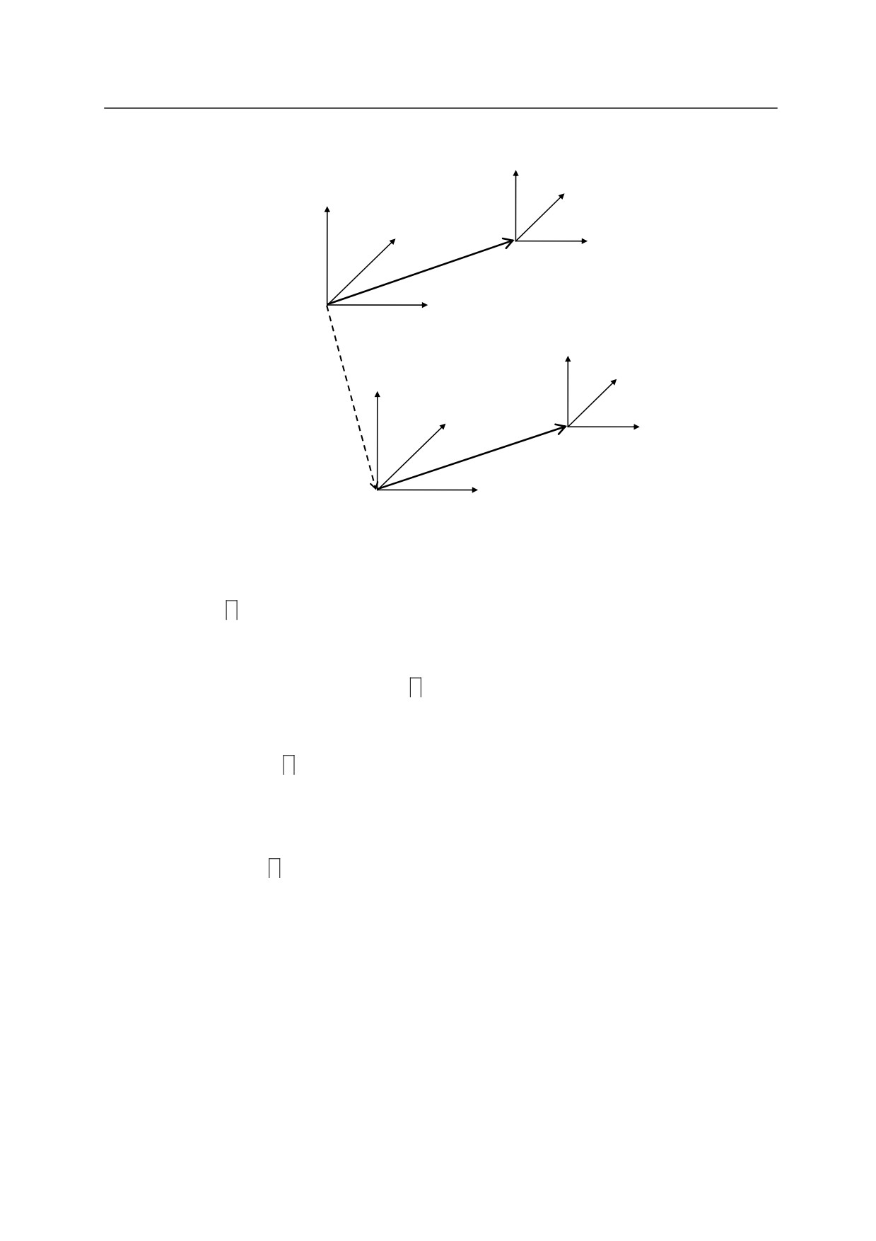
[ NOTE ]
BASE abc
BASE NULL
DO JMOVE def
DO JMOVE def
Even if the pose information “def ” are the same in both above examples, the destination of the
robot will differ according to the base transformation. See the diagram below.
5-61
5. Monitor Commands
Z
Y
Z
Y
X
def
Null base coordinate
X
Z
Y
abc
Z
Y
X
def
X
Example㻌
>BASE
Displays the current base transformation values.
X[mm] Y[mm] Z[mm] O[deg] A[deg] T[deg]
-300.
0.
0.
0.
0.
0.
Change? (If not , hit RETURN only)
>BASE NULL
Changes the base transformation value to the null base.
(X, Y, Z, O, A, T)=(0, 0, 0, 0, 0, 0)
>BASE abc
Changes the pose of the base coordinates to the pose described
by the base transformation value variable “abc”.
5-62
5. Monitor Commands
TOOL transformation value variable, tool shape number
Function㻌
Defines the tool transformation values, which specify the pose relation between the tool
coordinates and the null tool coordinates.
Parameter㻌
Transformation value variable
Specifies a pose variable defined by transformation values or compound transformation values.
Defines the new tool coordinates. The pose variable here describe the pose of the tool
coordinates with respect to the null tool coordinates, expressed in null tool coordinates. If no
pose variable is specified , the current tool transformation values are displayed.
Tool shape number
Specifies the tool shape to use for speed control in teach and check mode.
Explanation㻌
If “NULL” is designated for the parameter, the tool transformation values are set at “null tool”
(XYZOAT=0, 0, 0, 0, 0, 0,). The null tool coordinates have their origin at the center of the tool
mounting flange and the axes are parallel to the axes of the robot’s last joint. When the system
is initialized, the tool transformation values are set automatically at the null tool.
After a new tool transformation is set, the values (XYZOAT) and the message “Change?” are
displayed. To change the values, enter the new values separated by commas and press
. If no
parameter is specified, the current values are displayed.
When the robot moves to a pose defined by transformation values or is manually operated in base
mode or tool mode, the system automatically calculates the robot pose taking in consideration the
tool transformation values defined here.
When a pose variable is used as the parameter and if that pose variable is redefined, note that the
tool transformation must also be redefined using the TOOL command and the newly defined pose
as the parameter. The change made in the pose variable will then be reflected to the tool
transformation. See 11.4 Tool Transformation.
Example㻌
>TOOL grip
㻌 㻌
Changes the pose of the tool coordinates to the pose
described by the pose variable “grip”.
5-63
5. Monitor Commands
>TOOL NULL
Changes the tool transformation values to null tool.
(X, Y, Z, O, A, T)=(0, 0, 0, 0, 0, 0)
>TOOL tool1,1
Selects 1 for the tool shape number for the tool with tool
transformation values “tool1”
5-64
5. Monitor Commands
SET_TOOLSHAPE 㻌 tool shape no. = transformation value variable 1,㻌
transformation value variable 2,㻌 …,㻌 transformation value variable 8
Function㻌
Registers the tool shape used to control speed in teach mode and check mode.
Parameter㻌
Tool shape no.
Specifies the number of tool shape to register. Setting range: 1 to 9.
Transformation value variables 1-8
Specifies the points on the tool shape using transformation value variables. Maximum of 8
points can be specified. The points are specified in transformation values as seen from the
center of the flange surface. However, only the X,Y, Z values of the transformation values are
used for the tool shape registration.
Explanation
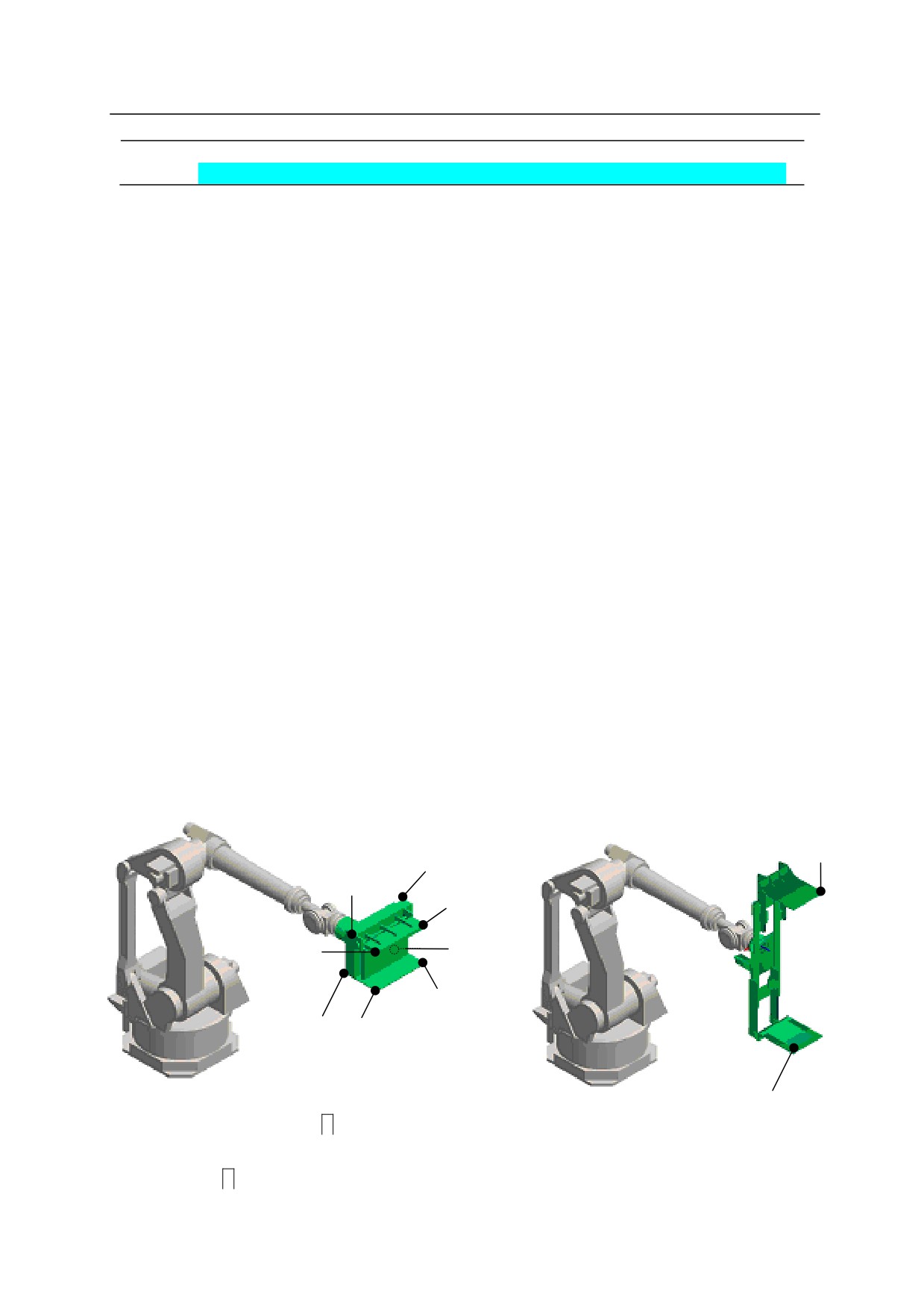
Defines the tool shape used for speed control in teach and check modes by maximum 8 points
specified in pose variables defined by transformation values (t1 to t8 in the figure below).
Speed should be controlled using tool shape in such cases where the tip of the tool is further away
from the flange surface than the TCP, or when the shape of the workpiece attached to the tool
should be put into consideration.
For tools registered via Aux. function 304, the tool shape can be registered via the screen that is
displayed when pressing <Tool Shape> on the same Aux. function 304 screen.
t2
t8
t7㻌
t6
t5㻌
t2
t4
t1
t3㻌
Example
t1
> SET_TOOLSHAPE 1=t1,t2,
Specifies tool edge positions of tool shape no.1 by
transformation value variables t1 and t2.
> TOOL tool1,1
Restricts the speed of edge points of tool shape no.1.
5-65
5. Monitor Commands
ENA_TOOLSHAPE tool shape no.㻌 = TRUE/ FALSE
Function㻌
Enables/ disables speed control in teach and check mode.
Parameter㻌
Tool shape number
Specifies in whole number from 1 to 9, the number of the tool shape to set enable/ disable.
TRUE/FALSE
Specify TRUE to enable speed control by the specified tool shape. Specify FALSE to disable
the speed control.
Explanation
Selects if speed control in teach and check modes are done by the specified tool shape or not.
FALSE is selected for all tool shapes as default setting. If TRUE is selected for a tool shape
number with not even one point specified, error E1356 Tool shape not set occurs when the robot
is operated in teach or check mode. To avoid this, always set at least one tool point via
SET_TOOLSHAPE command or change from TRUE to FALSE via this command an d then
execute TOOL or TOOLSHAPE command specifying the relevant tool shape number. (Once set
to TRUE, the setting will not be changed to FALSE unless TOOL/TOOLSHAPE command is
executed.)
5-66
5. Monitor Commands
TOOLSHAPE tool shape no.
Function㻌
Selects the tool shape used to control speed in teach mode and check mode.
Parameter㻌
Tool shape no.
Specifies the number of the tool shape used for speed control. Setting range: 1 to 9.
Explanation
To enable speed control in teach mode and check mode, the function must be enabled by
ENA_TOOLSHAPE command/ instruction (ENA_TOOLSHAPE n =TRUE). Error E1356 Tool
shape not set occurs if a tool shape with no point registered (all points set to 0) is selected.
Example
> TOOL tool1
Specifies the tool transformation values for the relevant tool as
> TOOLSHAPE 1
“tool1” and controls the speed using the tool points registered for
tool shape 1.
5-67
5. Monitor Commands
SETHOME accuracy, HERE
SET2HOME accuracy, HERE
Function㻌
Sets and displays the HOME pose.
Parameter㻌
Accuracy
Sets the accuracy range of the HOME pose in millimeters. The robot is at the HOME pose
when it nears HOME by the distance specified here. If not specified, the default value
1 mm is assumed.
HERE
Sets the current pose as HOME.
Explanation㻌
If no parameters are entered, the current values are displayed followed by the message “Change?”
Enter the desired value and press the
key. If no change is made, press only
.
Two HOME poses (HOME1 and HOME2) can be set in the AS system. HOME 1 is set using
SETHOME command, HOME 2 using SET2HOME command.
Example㻌
>SETHOME 2
Sets the accuracy at 2 mm, and changes the HOME pose
by entering the new values.
JT1 JT2 JT3
JT4
JT5
JT6 accuracy[mm]
0.
0.
0.
0.
0.
0.
2.
Change? (If not , hit RETURN only)
,90,-90
JT1 JT2 JT3
JT4
JT5
JT6 accuracy[mm]
0.
90.
-90.
0.
0.
0.
2.
Change? (If not , hit RETURN only)
>
>SETHOME
10,HERE
Sets the current pose as the HOME pose. The accuracy
is set at 10 mm; i.e. the dedicated signal HOME will be
output when the robot reaches the range of 10 mm from
the HOME pose.
5-68
5. Monitor Commands
ERRLOG
Function㻌
Displays the error log.
Explanation㻌
Displays the last one hundred errors. When the display reaches the end of the screen, press the
Spacebar to continue viewing. Errors are listed in chronological order.
(Auxiliary function 0702)
Example㻌
>ERRLOG
1-[02/07/17 09:55:45 (SIGNAL:00)
(D1016)
OPLOG
Function㻌
Displays the operation log.
Explanation㻌
Displays the last one hundred operations in the format shown below. When the display reaches
the end of the screen, press the
Spacebar to continue viewing.
(Auxiliary function 0703)
Example㻌
>OPLOG
1-[02/07/17 10:04:46](SIGNAL:00) [ PNL ]
5-69
5. Monitor Commands
SWITCH switch name, ……., switch name = ON
SWITCH switch name, ……., switch name = OFF
Function㻌
Displays and changes the system switches and their setting.
Parameter㻌
Switch name
Displays the specified switch. If not specified, all the switches are displayed. More than one
switch name can be entered separating each switch name by commas.
ON or OFF
Turns ON or OFF the specified system switch. If this parameter is not entered, the switch
setting is displayed.
Switches with * at the beginning of its name can be displayed only. The settings cannot be
changed.
Example
>SWITCH
Displays all system switches and their setting.
*POWER
ON
*REPEAT
ON
*RUN
ON
*CS
OFF
*RGSO
OFF
*ERROR
OFF
*TRIGGER
ON
*TEACH_LOCK OFF
CHECK.HOLD OFF
CP
ON
CYCLE.STOP OFF
OX.PREOUT ON
PREFETCH.SIGINS
OFF
QTOOL
OFF
REP_ONCE
OFF
RPS
OFF
STP_ONCE
OFF
AFTER.WAIT.TMR
ON
MESSAGES
ON
SCREEN
ON
AUTOSTART.PC OFF
AUTOSTART2.PC
OFF
AUTOSTART3.PCOFF
ERRSTART.PC OFF
DISPIO_01
OFF
HOLD.STEP OFF
FLOWRATE㻌 㻌 㻌 㻌 OFF
SPOT_OP
OFF
>
>SWITCH SCREEN,㻌 MESSAGE = OFF㻌
Turns OFF SCREEN and MESSAGE.
SCREEN
OFF
MESSAGE㻌 㻌 㻌 㻌 OFF
>
5-70
5. Monitor Commands
switch name, ……. ON
Function㻌
Turns ON the specified system switch.
Parameter㻌
Switch name
Turns ON the switch specified here. More than one switch name can be entered separating each
switch name with a comma.
The current setting of the switch can be checked using the SWITCH command.
Example㻌
>MESSAGES ON
Turns ON the switch MESSAGES.
㻌 㻌 㻌 㻌 㻌 㻌 >SCREEN, MESSAGES ON㻌
Turns ON the switches MESSAGES and
SCREEN.
switch name, ……. OFF㻌
Function㻌
Turns OFF the specified system switch.
Parameter㻌
Switch name
Turns OFF the switch specified here. More than one switch name can be entered separating
each switch name with a comma.
The current setting of the switch can be checked using the SWITCH command.
Example㻌
>MESSAGES OFF
Turns OFF the switch MESSAGES.
㻌 㻌 㻌 㻌 㻌 㻌 >SCREEN, MESSAGES OFF㻌
Turns OFF the switches MESSAGES and
SCREEN.
5-71
5. Monitor Commands
ZSIGSPEC
㻌
Function㻌
Displays and changes the total number of external and internal I/O signals.
Explanation㻌
The current setting and the message “Change?” are displayed. This command changes only the
software setting. Make sure the number of signals corresponds with the hardware setting.
Example㻌
>ZSIGSPEC
DO, DI, INT㻌 㻌
㻌 㻌 (DO=Ext. output signal, DI= Ext. input signal, INT=Int. signal)
64
64
128
Change? (If not , hit RETURN only)
32,32,32
DO, DI, INT
32
32
32
Change? (If not , hit RETURN only)
5-72