Kawasaki Robot Controller E Series. Reference Manual (2015) - page 3
4. AS Program
.PROGRAM demo
1 ? OPENI
2 ? JAPPRO #part, 50
3 ?
Enter the rest of the program in the same manner. Correct any mistakes when entering the steps
by pressing
Backspace before pressing
.
If the
key is hit at the end of an erroneous step, error message appears and that step is rejected.
In this case, enter the step again. When the entire program has been entered, the screen should
appear as follows:
>EDIT demo
.PROGRAM
1 ? OPENI
2 ? JAPPRO #part,50
3 ? LMOVE #part
4 ? CLOSEI
5 ? LDEPART 150
6 ? JAPPRO #box,200
7 ? LMOVE #box
8 ? OPENI
9 ? LDEPART 180
10 ? E
>
The last step “E
” is not a command for the robot but a command to exit the Editor mode (see
the table in 4.2.1). The program is now complete. When the program is executed, the AS
system follows the steps in order, from step 1 to step 9.
See 11.0 Sample Programs for further information on how to create programs.
4-7
4. AS Program
4.3 PROGRAM EXECUTION
The robot control programs and the PC programs are executed in different ways.
4.3.1 EXECUTING ROBOT CONTROL PROGRAMS
To execute a program, turn the
TEACH/REPEAT switch to REPEAT position. Next, ensure
the
TEACH LOCK switch on the teach pendant is in the OFF position. Then, turn ON the
motor power and change the HOLD/RUN state from HOLD to RUN.
1. Running program via EXECUTE command
First, set the monitor speed. The robot will move at this speed when the program is executed.
The speed should be set under 30%, with the initial setting at 10%.
> SPEED 10
To start execution, use the EXECUTE command. Type as below:
> EXECUTE demo
The robot should then perform the selected task. If it does not move as expected, change
from RUN to HOLD. The robot will decelerate and stop. In case of emergency, press the
EMERGENCY STOP button on the controller operation panel or on the teach pendant. The
brakes are applied and the robot stops immediately.
If the robot moves correctly at 10% speed, gradually raise the speed.
> SPEED 30
> EXECUTE demo
The robot operates at 30% speed.
> SPEED 80
> EXECUTE demo
The robot operates at 80% speed.
After the EXECUTE command has been issued at least once,
A +
CYCLE START can be
used to execute programs.
To execute the program more than once, enter the number of repetitions after the program
name:
> EXECUTE demo,5
Executes 5 times.
> EXECUTE demo,1
Runs the program continuously.
4-8
4. AS Program
2. Running program via PRIME command
Set the monitor speed in the same way as with the EXECUTE command, and execute PRIME
command.
>PRIME demo
Robot is now ready to execute the program. Pressing
A +
CYCLE START begins execution.
Execution can also be started using the CONTINUE command.
3. Running program via STEP command or
CHECK GO/BACK key
It is possible to check the motion and the contents of a program by executing the program step
by step. Use either the STEP monitor command or the
CHECK GO/BACK key* on the teach
pendant.
Note* When using the
CHECK GO/BACK key, the program execution pauses at the end of
each motion instruction.
During execution of the robot control program, some monitor commands are disabled. Likewise,
the EXECUTE command cannot be entered twice during execution.
4.3.2 STOPPING PROGRAMS
There are several ways to stop a program in progress. The following three are described in order
from most to least urgent.
1. Press the
EMERGENCY STOP button either on the controller panel or on the teach pendant.
Breaks are applied and robot stops immediately. Unless there is an emergency, use methods
2 and 3.
2. Change from RUN to HOLD. The robot slows down and stops.
3. Entering the ABORT command stops the program execution after the robot completes the
current step (motion instruction).
> ABORT
HOLD command can also be used to stop execution.
> HOLD
4-9
4. AS Program
4.3.3 RESUMING ROBOT CONTROL PROGRAMS
Depending on how the program was stopped, there are several methods to resume the program.
1. When the robot was stopped with
EMERGENCY STOP button, release the lock of
EMERGENCY STOP, and turn ON the motor power. Robot starts moving when you press
A +
CYCLE START.
2. When
HOLD was used to stop the robot, press
A+
RUN to change to RUN.
3. To resume after ABORT or HOLD command or when program execution was suspended by
an error, use CONTINUE command. 䠄When restarting after an error, the error should be
reset before resuming the program. 䠅
> CONTINUE
4.3.4 EXECUTING PC PROGRAMS
PC programs are executed by PCEXECUTE monitor command or by a program instruction that
is executed from within a robot control program. PCABORT command can be used to stop
execution of the PC program at any time. PCEND command ends the execution of the program
after the current cycle is completed.
PCCONTINUE command resumes execution of a program suspended by either PCABORT or
because of an error.
(When restarting after an error, the error should be reset before resuming
the program.)
4-10
4. AS Program
4.4 PROGRAM EXECUTION FLOW
The program instructions are regularly executed in order from top to bottom of the program.
This consecutive flow is changed when there is an instruction such as GOTO or IF
GOTO. A
CALL instruction calls up and executes a different program, but this does not change the order of
the flow. When a RETURN instruction is executed, the processing returns to the caller program
and resumes from where it has left.
WAIT instruction stops the program from proceeding to the next step until the specified condition
is met. PAUSE and HALT instructions stop the program at the step where these instructions are
used.
STOP instruction may not stop the execution in some cases. If the specified execution cycles
remain, execution continues with the first step in the main program.
(Even if the STOP
instruction is executed in a subroutine, the execution returns to the beginning of the main
program.) If there are no cycles remaining, the execution stops at the step where the instruction
is used.
4.4.1 SUBROUTINE
A main program can be temporarily suspended and a different program, called the subroutine, can
be called up and executed. By using the subroutine, you can make the program into a modular
structure that is easier to understand.
4.4.2 SUBROUTINE WITH PARAMETERS
Parameters can be used with subroutines for more convenience. For example, when a
calculation that uses different input data is done repetitively, create a subroutine to do the
calculation. Use the CALL instruction to branch to the subroutine, and use the input data as
parameters in the calculation.
(See examples 1 and 2 below)
Up to 25 parameters can be set using real variables, pose variables or string variables. The
variable type must be the same in the main program and the subroutine. When assigning
transformation values to a parameter put a “&” in front of the parameter variable name in order to
differentiate it from real number variables. Also, use local variables in the CALL destination
(subroutine).
4-11
4. AS Program
Example 1 The value of real number variable “c” is the sum of input data “a” and “b”.
main()
1 a=1
2 b=2
3 CALL calc(a,b,c)
4 TYPE c
calc(.aa,.bb,.cc)
1 .cc=.aa+.bb
Example 2
The value of transformation value variable “c” is the sum of transformation
value of “a” and “b”.
pose()
1 point a = trans(10)
2 point b = trans(0,20)
3 CALL add(&a,&b,&c)
4 point d = c
add(.&aa,.&bb,.&cc)
1 point .cc=.aa+.bb
[ NOTE ]
To set parameters in the subroutine, as in example 1 above, enter “EDIT calc,
0” then the following appears in the display:
0.()
0?
Enter (.aa,.bb,.cc) after the ?.
4.4.3 ASYNCHRONOUS PROCESS (INTERRUPTION)
Under certain conditions, like when an error occurs or when a specific external signal is input,
program execution may be interrupted and another program will be executed. This occurs
independently from the flow of execution of the main program and is called asynchronous
processing (interruption). As soon as the specified signal (e.g. an external signal or an error) is
detected, the interruption occurs regardless of the execution of the main program. This process
is activated using the ON (or ONI) ...CALL instruction.
4-12
4. AS Program
4.5 ROBOT MOTION
4.5.1 TIMING OF ROBOT MOTION AND PROGRAM STEP EXECUTION
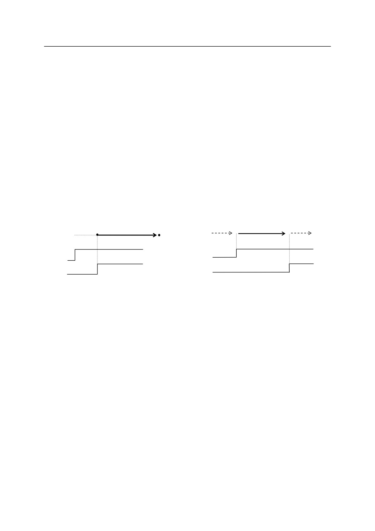
In the AS system, the timing of program execution and of the robot motion can be changed by
setting the system switches. For example, the timing of step execution changes as following
when PREFETCH.SIGINS switch is turned ON (allow early processing of signal I/O commands)
or OFF (not allow early processing of signal I/O commands).
JMOVE part1
SIGNAL 1
JMOVE part2
SIGNAL 2
PREFETCH.SIGINS ON
PREFETCH.SIGINS OFF
part.1
part.2
part.1
part.2
䞉
䞉
SIG 1
SIG 1
SIG 2
SIG 2
When PREFETCH.SIGINS is ON, the external signal 1 (SIGNAL 1) is output as soon as the
robot starts moving toward part1. When the program reaches the second JMOVE instruction, it
waits until the robot reaches part1 before performing that instruction. As soon as the robot
reaches part 1, it starts for part 2, and at the same time, external signal 2 (SIGNAL 2) is output.
When PREFETCH.SIGINS is OFF, the signals are output after the robot reaches the destination
of the motion instructions and the axes coincide.
The sample below demonstrates how the program steps are executed in AS system when
PREFETCH.SIGINS is ON.
4-13

4. AS Program
1 JMOVE
#b
Signal 2 output
2 SIGNAL
1
#a
#b
3 a=2
Signal 1 output
4 LMOVE
#c
5 SIGNAL
2
6 SPEED
50
7 LMOVE
#d
Signal 3 output
#c
Speed 50 %
8 SIGNAL
3
#d
after #c.
The signal is processed in advance when PREFETCH.SIGINS is ON, therefore all the
instructions up to the next motion instruction are executed as soon the robot starts executing the
current motion instruction. If the above program is executed when the robot is at #a, the steps
proceed in the following order:
1. At #a, the robot plans the motion for JMOVE #b and starts moving toward #b.
2. As soon as the motion starts, the next step, SIGNAL 1, is executed, i.e., signal 1 is turned on
right after the robot departs #a.
3. The execution proceeds to step 4, plans LMOVE #c and waits for the robot to reach #b.
4. As soon as the robot reaches #b, the robot starts moving toward #c. The execution proceeds
to step 7 (plans motion for LMOVE #d), and waits for the robot to reach #c.
[ NOTE ]
When PREFETCH.SIGINS is ON, the program processes the next step until it
has to wait for the robot to reach the specified pose. However, the timing is
affected by other settings and command/ instructions such as WAIT instruction or
the CP switch. WAIT instruction suspends the processing of steps until the
given condition is satisfied. When the CP switch is OFF, the program processes
all the steps before the step that includes motion instruction, and stops there
before proceeding. Keep in note the settings of the system switches and
instructions when programming.
As demonstrated here, it is important to note that the timing in which the AS system processes the
program and in which the robot moves are affected by the system switch settings and some
certain program instructions. Pay careful attention to the output timing of signals during
programming.
For details on each system switch, refer to 7.0 AS System Switch or the Operation Manual.
4-14

4. AS Program
4.5.2 CONTINUOUS PATH (CP) MOTION
This example shows the execution of one motion instruction.
Current pose
・pick
(v)
JMOVE pick
STOP
Speed
(t) time
When executing a motion instruction like the one above, the robot accelerates smoothly up to the
current speed setting as it moves towards the pose “pick”. As the robot approaches “pick”, it
gradually decelerates until it stops at the pose. Series of motions such as this, carried out by one
motion instruction, is called a “motion segment”.
In the case for the figure below, if the CP system switch is ON, the robot first accelerates to reach
the specified speed, but does not decelerate when it approaches pos.1. Instead, it makes a
smooth transition to the motion toward pos.2. When the robot approaches pos.2, it gradually
decelerates and stops at that point. This motion consists of two motion instructions, and is thus
structured by two motion segments.
(v)
JMOVE pos.1
Speed
JMOVE pos.2
STOP
(t) time
Motion like this, where the robot performs a series of motions making a smooth transition
between the motion segments without stopping at each destination, is called CP (Continuous
Path) motion. Turning OFF the CP system switch disables the CP function. If the CP switch is
turned OFF, the robot will decelerate and stop at the end of each motion segment.㻌 㻌 䠄See 5.6
SWITCH and ON/OFF command, 6.9 ON/OFF instruction on how to set the CP switch䠅.
CP motions can be used in both linear motions and joint interpolated motions or in a combination
of them. For example, CP motions can be used throughout all of the following steps:
linear motion (e.g. LDEPART) joint interpolated motion (e.g. JAPPRO) linear motion (e.g.
LMOVE).
4-15
4. AS Program
4.5.3 BREAKS IN CP MOTIONS
Some instructions can suspend the execution of a program until the robot actually reaches the
destination pose. This is called the break in CP motions. These instructions are useful when
the robot should be stationary while certain operations are performed (e.g. closing the hand).
See the example below.
Current pose
pos.1
JMOVE pos.1
BREAK
SIGNAL1
SIG1
The JMOVE instruction starts moving the robot toward pos.1. Next, the BREAK instruction is
executed. This instruction suspends the execution of the program until the movement towards
pos.1 is completed. In this way, the external signal is not output until the robot comes to a stop.
The following instructions suspend program execution until the robot movement is completed.
However, be careful not to use these instructions when the robot should be moving.
BASE BREAK BRAKE CLOSEI HALT OPENI PAUSE RELAXI
TOOL ABOVE BELOW DWRIST UWRIST LEFTY RIGHTY
In addition to the above, ONI instruction also interrupts the program execution, but note that the
break set by ONI instruction may occur at any place of the motion segment.
4-16
4. AS Program
1. The robot decelerates and stops if an instruction is not given before the
execution of the current motion is completed. Some of the reasons that
cause such situation are:
(1) The WAIT instruction is executed but the conditions to resume the program
are not set before robot movement is completed.
(2) Program steps before the next motion instruction are not completed before
the current motion finishes.
2. When moving in CP motion, a certain amount of time is required to
calculate the condition for smooth transition to the next motion segment.
Therefore, if the distance between the two points is too short, the calculation
time may become insufficient and cause the robot to stop in between the
motion segments. To avoid this, it is necessary to slow down the speed.
If the speed is not to be changed, do not specify the points unnecessarily
close together.
4.5.4 RELATION BETWEEN CP SWITCH AND ACCURACY, ACCEL, AND DECEL
INSTRUCTIONS
ACCURACY instruction: Sets the robot’s positioning accuracy at the end of each motion
segment.
(When the robot enters the range set by this instruction, it
considers that it has reached the destination, and starts the movement
for the next destination.)
·ACCEL instruction:
Sets acceleration of the robot at the beginning of a movement.
·DECEL instruction:
Sets deceleration of the robot at the end of a movement.
·CP Switch:
Enables or disables CP motion.
4.5.4.1 CP ON: MOTION TYPE 1 (STANDARD)
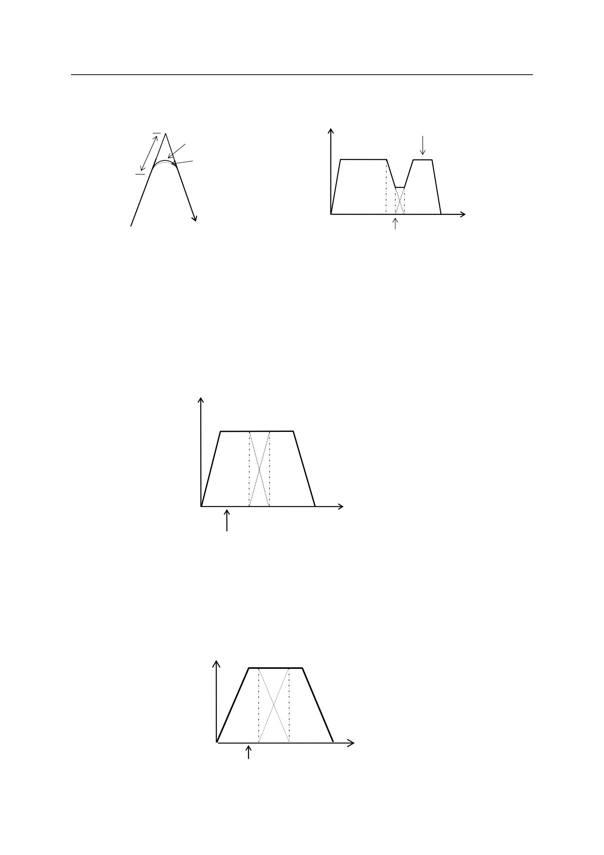
For example the robot takes the motions below with the CP switch ON: A BC.
As soon as the current pose values for the robot enters the accuracy range (i.e. robot reaches point
D), superposing begins of the values of the current motion path with the motion command values
for the next path. The robot will shift movement continuously toward the next path according to
4-17
4. AS Program
these command values.
Speed(v)
B
command value
Trajectory per instruction
ACCURACY
Actual trajectory
(deviation due to delay)
D
Time (t)
A
E
(B)
C
C
A
Robot reaches D
The greater the range specified by ACCURACY, the earlier the superposing will begin.
However, acceleration on the next path does not begin before the point where the robot starts to
decelerate (point E). Therefore, it can be said that the ACCURACY effect is saturated at a
certain value, i.e. there is no effect in setting the accuracy value greater than the distance between
point B and E. (See the diagram below.)
Speed(v)
A
E
(B)
C
Time (t)
Even if command value reaches the accuracy point at this time, acceleration for next
path will not start until deceleration begins at point E.
If the acceleration and the deceleration values are set smaller, the superposing begins earlier and
the robot will move in a trajectory with larger radius, but the total time it takes to reach C does not
differ significantly.
Speed(v)
Time(t)
A
E
(B)
C
ACCURACY
4-18
4. AS Program
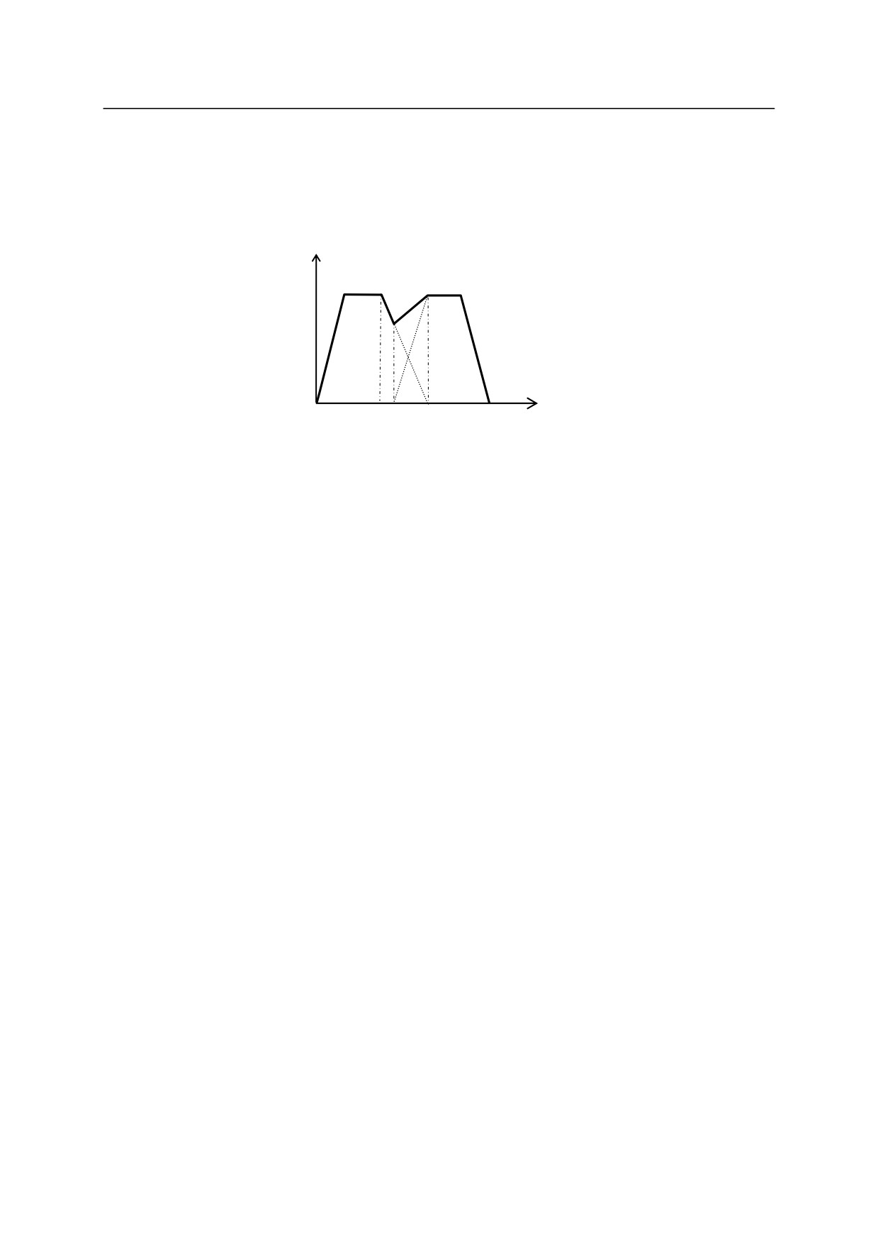
Even if the deceleration is decreased and the acceleration for the next path is increased, the
compound speed will not exceed the specified maximum speed, since the superposing does not
begin until the robot reaches point F (the point where acceleration starts). In other words, the
time taken to complete deceleration and acceleration is the same (point B).
Speed (v)
Time (t)
A
E F
(B)
C
4.5.4.2 CP ON: MOTION TYPE 2
In motion type 2, the concept of accuracy and velocity in linear motion and circular motion is
different from that of Standard motion type described above. Standard motion type and motion
type 2 can use the same programs without modifications, but the actual motion path and motion
speed will change.
1. Accuracy setting
(1) Accuracy in joint interpolated motion
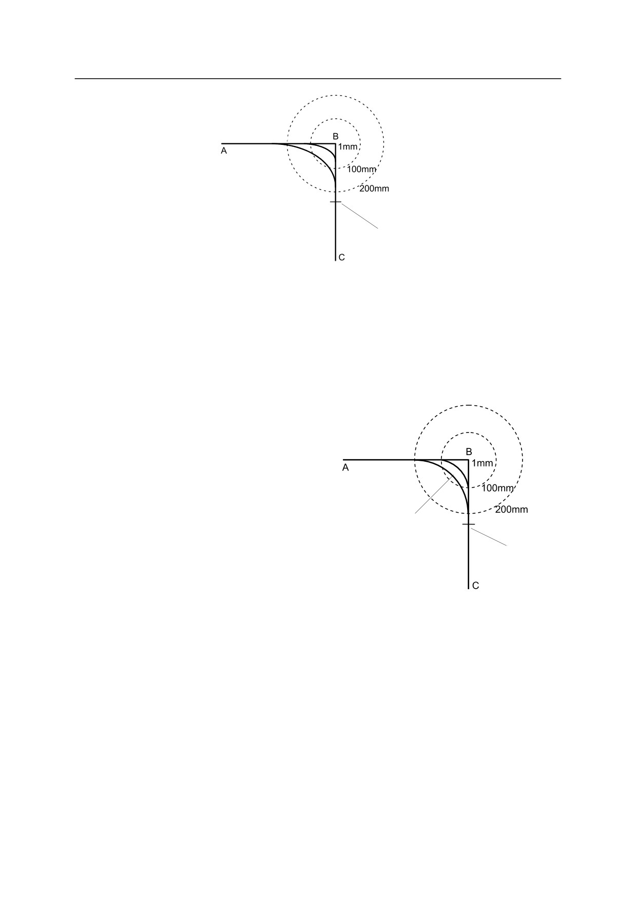
The motion path of the robot corresponding to the accuracy setting is shown in the figure
below. In this example the accuracy values at point B are 1 mm, 100 mm, and 200 mm.
In the same way as Standard motion, the robot starts to shortcut before reaching point B, but
does not necessarily start turning at the point where it enters the accuracy range. How close
the robot approaches point B before turning is determined by the angle of each axis
calculated proportionally to the accuracy value. By setting the accuracy value larger, the
robot can shortcut the shorter distance of either the remaining distance of the current path or
half the distance of the next path from B to C.
4-19
4. AS Program
Joint interpolated motion
Maximum shortcut:
half the distance of
next path
(2) Accuracy in linear and circular interpolation motion
The motion trajectory of the robot corresponding to the accuracy setting is as shown in the
figure below. In this example the accuracy values at point B are 1 mm, 100 mm, and 200
mm. The robot starts turning at the point where it enters the accuracy range. The robot
follows a circular trajectory within the radius of accuracy range.
By setting the accuracy range larger,
the robot can shortcut the shorter
Linear interpolated
distance of either the remaining
motion
distance of the current path or half
the distance of the next path from B
to C. The accuracy value can be set
up to the value equal to half the
Circular arc
distance of the second path.
Maximum shortcut
half the distance of
By shortcutting, the cycle time can
next path
be shortened. However, when the
following conditions are set, the processing of the accuracy setting will be the same as in
Standard motion:
· When a waiting instruction (TWAIT, SWAIT, etc.) is executed at point B.
· When a workpiece/tool is changed at point B.
· When the interpolation mode for the next point is changed to joint interpolation.
· When the motion mode is changed at point B. (ordinary mode motion based on the
fixed tool coordinates)
· When the processing branches due to conditions set by instruction such as IF and END.
4-20
4. AS Program
2. Speed setting
(1) Speed in joint interpolated motion
Same as in Standard motion type.
(2) Speed in linear and circular interpolated motion
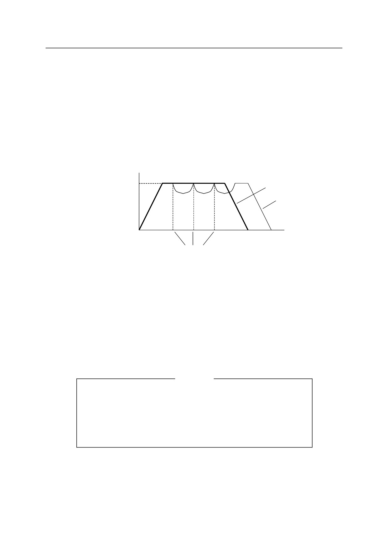
In motion type 2, if the accuracy value is set larger and the configuration of the robot does
not change between two defined poses, the specified speed is attained even if the distance
between the two poses is small.
Velocity
Motion type 2
Specified speed
Motion type 1
(standard)
Time
Axis coincidence
in motion type 1
However, when the following conditions are set, the process will be the same as in Standard
motion type:
· When a waiting instruction (TWAIT, SWAIT, etc.) is executed at point B.
· When a workpiece/tool in changed at point B.
· When the interpolation mode for the next point is changed to joint interpolation.
· When the motion mode is changed at point B. (ordinary mode motion based on the
fixed tool coordinates)
· When the processing branches due to conditions set by instruction such as IF and END.
[ NOTE ]
When attempting to execute a program where the robot orientation
changes greatly within a short distance, the time it takes to change the
orientation will exceed the time it takes to move that distance at the
specified speed. In this case, the joint movements are given priority, thus
the motion will not reach the specified speed.
4-21
4. AS Program
(3) 㻌 Speed in circular interpolation
In motion type 2 the maximum speed is automatically set according to the robot’s capacity
to carry out proper circular interpolation motion.
In motion type 2, the robot follows a circular trajectory within the accuracy range circle. The
maximum speed of this trajectory is also set by the robot’s capacity.
3. Precautions for programming in motion type 2
In motion type 2, the motion is planned with the next motion instruction as the target value. For
example, in the figure below, the pose information for point C is used as reference in motion from
point A to point B.
ACCURACY 100 ALWAYS
LMOVE A
LMOVE B
LMOVE C
When programming in motion type 2, make sure that the target value of the next motion is
determined (example: LMOVE C) before executing a motion instruction step (example: LMOVE
B).
For example, the following programming must not be done:
LMOVE B
POINT C = pos[1]
LMOVE C
In this example, the pose information (C) for the second motion instruction is set between motion
LMOVE B and LMOVE C. This is incorrect and error (E0102) “Variable is not defined” will
occur. This program must be written as below:
POINT C = pos[1]
LMOVE B
LMOVE C
As in the example above, the target value for the next motion instruction (example: LMOVE C)
should be defined before executing the motion instruction step (example: LMOVE B).
4-22
4. AS Program
4.5.4.3 CP OFF
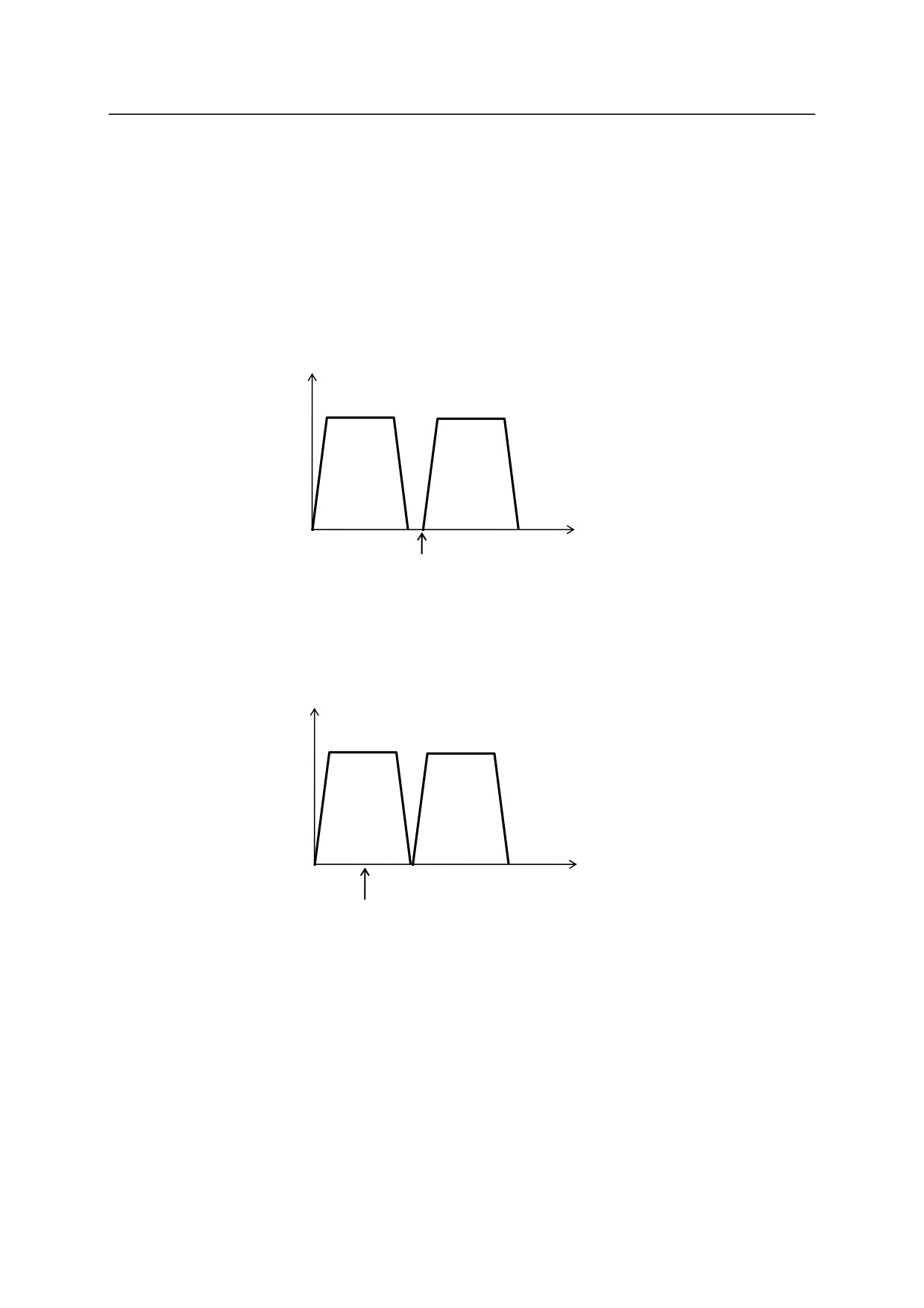
When the CP switch is OFF, there is no superposing of motions. The acceleration for the second
path starts after the first motion segment is completed and the current value enters the
ACCURACY* range.
Note* For example, for RS2ON, the default value is 1 mm.
Speed(v)
A
C
Time(t)
The point where the current value enters
the accuracy range of point B
When the CP switch is OFF, the motion for the second path begins only when the deceleration
speed of the first motion reaches zero, even if the accuracy range is set larger than the end of the
first path.
Speed(v)
A
B
C
Time(t)
Current value enters the
accuracy range
4-23
4. AS Program
4.5.5 MOTION ALONG SPECIFIED PATH
Linear interpolated and joint interpolated motions are standard functions on all the robots.
However, occasionally it is necessary to move the robot along a specified or calculated path.
The AS system can run calculations while the robot is moving, making it possible to realize
complex motions. This feature is called “Motion along a specified path”.
The system enables the motions via a program loop that performs a series of continuous
calculations of short-distance motions performed while motion instructions are executed. Such
a program loop is possible because AS can perform non-motion instructions while the robot is
moving. The calculated motion segments are connected smoothly using the CP function.
The following is an example of a program for motion along a specified path. The robot tool will
follow the path defined by a series of pose data specified by the array variable “path”.
FOR index=0 TO 10
LMOVE path[index]
END
Array variables path[0] to path[10] are to be defined by manual teaching or by
calculation.
In this example, END instruction exists between the first LMOVE and the next LMOVE, so the
motion type for this program is standard motion type and not motion type 2. (Refer to 4.5.4.2).
4.5.6 SETTING LOAD DATA
By setting the load data for the robot’s current motion, the optimal acceleration and deceleration
for the load are determined automatically. Set the correct load data according to the robot’s
current motion.
!
CAUTION
Always set the correct load mass and center of gravity location. Incorrect data
may weaken or shorten the longevity of parts or cause overload / deviation
errors. For detailed information see WEIGHT command / instruction.
The load data can be set automatically by using the auxiliary function 0406
Auto Load Measurement. See the Operation Manual for details.
4-24
5. Monitor Commands
5.0 MONITOR COMMANDS
This chapter groups the monitor commands in the following categories, and describes each
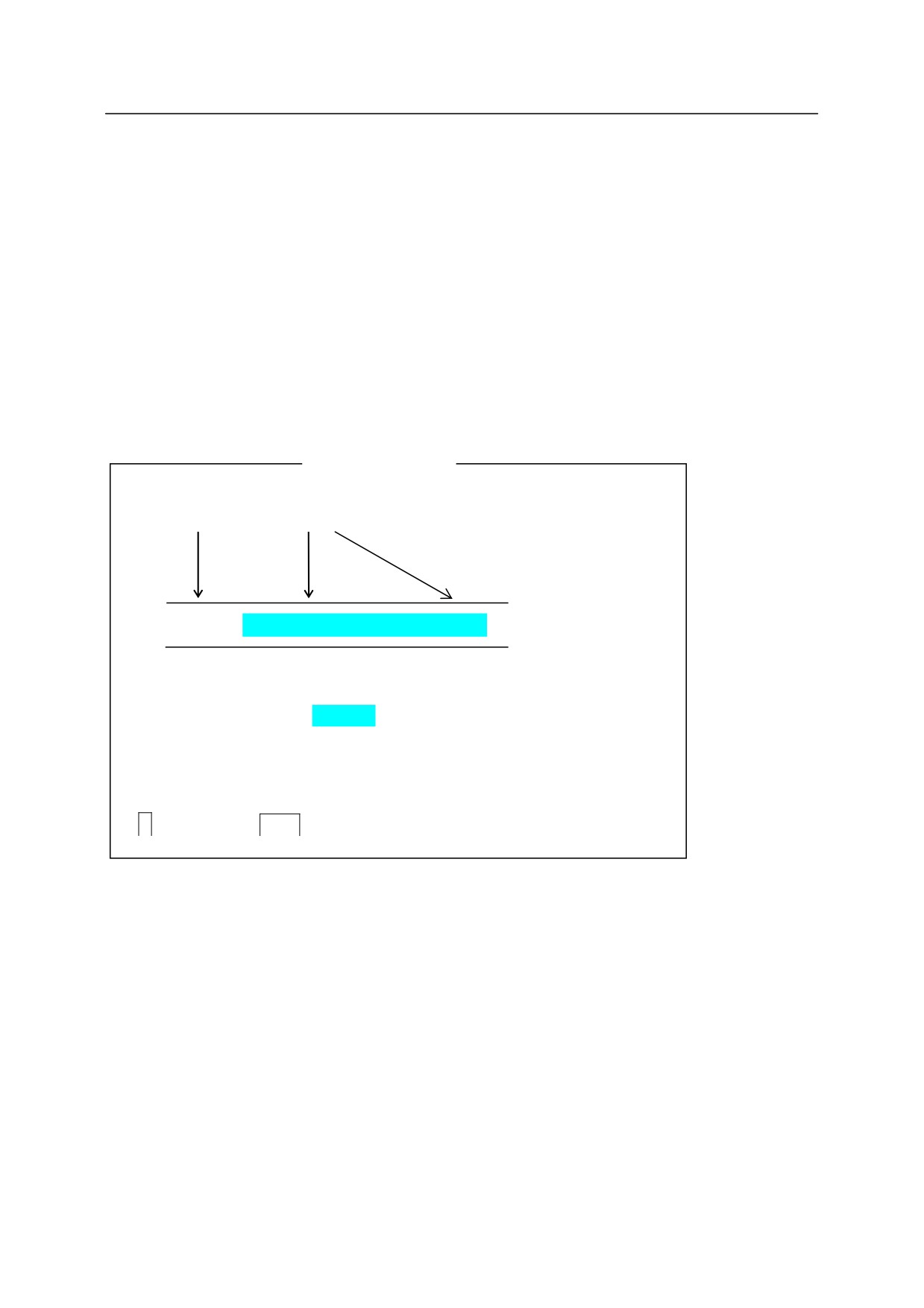
command in detail. A monitor command consists of a keyword expressing the command and
parameter(s) following that key word, as shown in the example below.
EXAMPLE
Keyword Parameter
EDIT program name, step number
Parameters marked with
can be omitted.
Always enter a space between the keyword and the parameter.
represents the
Enter key in the examples.
5-1
5. Monitor Commands
5.1 EDITOR
COMMANDS
EDIT
Starts program editor.
C
Finishes editing current program and changes to another
program (Change).
S
Selects program step to display (Step).
P
Displays specified number of program steps (Print).
L
Selects the previous step (Last).
I
Inserts a new step (Insert).
D
Deletes program steps (Delete).
F
Searches for characters (Find).
M
Replaces characters (Modify).
R
Replaces characters (Replace).
O
Places the cursor on the current step (One line).
E
Exits editor (Exit).
XD
Cuts and stores the selected step or steps in clipboard.
XY
Copies and stores the selected step or steps in clipboard.
XP
Pastes content of the clipboard.
XQ
Pastes content of the clipboard in the reverse order.
XS
Shows the contents of the clipboard.
T
Teaches motion instructions while in editor mode. (Option)
5-2
5. Monitor Commands
EDIT program name , step number
Function
Enters the editor mode that enables program creation and editing.
Parameter
Program name
Selects a program for editing. If a program name is not specified, then the last program edited
or held (or stopped by an error) is opened for editing. If the specified program does not exist, a
new program is created.
Step number
Selects the step number to start editing. If no step is specified, editing starts at the last step
edited. If an error occurred during the last program executed, the step where the error occurred
is selected.
[ NOTE ]
A program cannot be edited during execution.
A program cannot be executed or deleted while it is being edited. If a program calls a
program that is being edited, an error occurs, and the execution of that program stops.
5-3
5. Monitor Commands
C program name , step number
Function
Changes the program currently selected in editor mode.
Parameter
Program name
Selects the program to be edited.
Step number
Selects the step number to start editing. If no step is specified, the first step of the program is
selected.
S step number
Function
Selects and displays the specified step for editing. (Step)
Parameter
Step number
If no step is specified, the first step of the program is selected. If the step number is greater than
the number of steps in the program, a new step following the last step in the program is selected.
5-4

5. Monitor Commands
P number of steps
Function
Displays the specified number of steps starting with the current step.
Parameter
Number of steps
Sets the number of steps to display. If the number of steps is not specified, only the current step
is displayed.
Explanation
Displays only the specified number of steps. The last step on the list is ready for editing.
L
Function
Displays the previous (last) step for editing.
([Current step number] 1=[step number of the step to be displayed])
5-5

5. Monitor Commands
I
Function
Inserts lines before the current step.
Explanation
The steps after the inserted line are renumbered. To exit insert mode, press the
key.
All
lines written before exiting the insert mode are inserted in the program.
Example
CLOSEI instruction is inserted between steps 3 and 4.
1?OPENI
2?JAPPRO #PART, 500
3?LMOVE #PART
4?LDEPART 1000
5? S
4
;Display step 4 to insert a line before it.
4
LDEPART 1000
4? I
;Type the I command.
4I CLOSEI
;Type in the instructions for the inserted line.
5I
;Press enter to finish inserting the lines.
5
LDEPART 1000
;Step 4 is now renumbered as step 5.
5?
[ NOTE ]
To insert blank line, press
Spacebar or
TAB, then
while in the insert mode.
5-6
5. Monitor Commands
D number of steps
Function
Deletes the specified number of steps including the current step.
Parameter
Number of steps
Specifies number of steps to delete beginning with the current step. If no number is specified,
only the current step is deleted.
Explanations
Deletes only the specified number of steps beginning with the current step. Once deleted, all
remaining steps are automatically renumbered and displayed.
[ NOTE ]
If the number of steps specified is greater than the number of steps in the program,
all the steps after the current step are deleted.
F character string
Function
Searches (finds) the current program for the specified string from the current step to the last, and
displays the first step that includes the string.
Parameter
Character string
Specifies the string of characters to be searched.
Example
Searches for character string “abc” in steps after the current step and displays the step containing
that string.
1?F abc
3
JMOVE abc
3?
5-7
5. Monitor Commands
M /existing characters/ new characters
Function
Modifies the characters in the current step.
Parameter
Existing characters
Specifies which characters are overwritten in the current step.
New characters
Specifies the characters that replace the existing characters.
Example
Modifies step 4 by replacing the pose variable abc with def.
4
JMOVE abc
4?M/abc/def
4
JMOVE def
4?
5-8
5. Monitor Commands
R character string
Function
Replaces existing characters in the current step with the specified characters.
Parameter
Character string
Specifies the new characters that replace the existing characters.
Explanation
The procedure for using the R command is as follows:
1. Using the
Spacebar, move the cursor under the first character to replace.
2. Press the
R key and then the
Spacebar.
3. Enter the new replacement character(s). Note that the characters entered do not replace
characters above the cursor but those two spaces to the left, starting above the R. (See example
below)
4. Press
.
Once
is pressed, the AS system checks if the line is correct. If there is an error, the entry is
ignored.
Example
The speed is changed from 20 to 35 using the R command.
1
SPEED 20 ALWAYS
1?
R 35
1
SPEED 35 ALWAYS
1?
5-9
5. Monitor Commands
O
Function
Places the cursor on the current step for editing.
(“O” for “one line”, not zero).
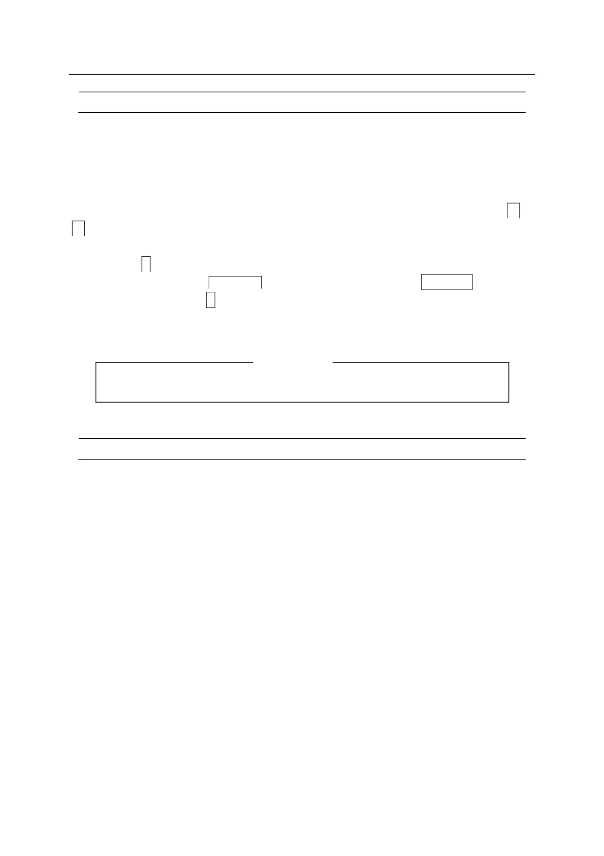
Example
The pose variable abc is changed to def using the O command. The cursor is moved using
or
key.
3
JMOVE abc
3?O
3
JMOVE abc
BackSpace
; delete “abc” using
Backspace
3
JMOVE def
; Enter “def”
3
JMOVE def
3?
[ NOTE ]
This command cannot be used via teach pendant.
E
Function
Exits from the editor mode and returns to monitor mode.
5-10
5. Monitor Commands
XD number of steps
Function
Cuts the specified number of steps from a program and stores them in the paste buffer.
Parameter
Number of steps
Specifies number of steps to cut and store in the paste buffer beginning with the current step.
Up to ten steps can be cut. If not specified, only the current step is cut.
Explanation
Cuts the specified number of steps and stores them in the paste buffer.
The XY command copies and does not cut the steps, but the XD command cuts the steps. The
remaining steps in the program are renumbered accordingly.
XY number of steps
Function
Copies the specified number of lines and stores in the paste buffer.
Parameter
Number of steps
Specifies number of steps to copy and store in the paste buffer. Up to ten steps can be copied.
If the number is not specified, only the current step is copied.
Explanations
Copies the specified number of steps including the current step and stores them in the paste
buffer.
The XD command cuts the steps, but XY command copies the steps. The program remains the
same and step count does not change after the XY command is used.
5-11
5. Monitor Commands
XP
Function
Inserts the contents of the paste buffer before the current step.
Explanation
Use the XD or XY command prior to this command to store the desired contents in the paste
buffer.
XQ
Function
Inserts the contents of the paste buffer before the current step with the contents being inserted in
reverse order.
Explanation
Inserts the contents of the paste buffer in reverse order as it would be inserted using XP
command.
5-12