Kawasaki Robot Controller E Series. Reference Manual (2015) - page 1
PREFACE
This manual describes the AS* language used in the Kawasaki Robot Controller E series. The
objective for this manual is to provide detailed information on the outline of the AS system, basic
usages, data types, robot trajectory control and all the commands/instruction to allow effective
usage of the AS system. The robot operation procedures are not included here, so refer to the
Operation Manual for that information. This manual should be read with careful review of the
related manuals listed below. Once the contents of all the manuals are thoroughly read and
understood the robot can be used.
1. Safety Manual
2. Installation and Connection Manual for Arm
3. Installation and Connection Manual for Controller
4. External I/O Manual (for connecting with peripheral devices)
5. Inspection and Maintenance Manual
The contents of this manual are described on condition that installation and connection of the
robot are done in accordance with the above listed manuals.
The explanations in this manual include information on optional functions, but depending on the
specification of each unit, not every optional function detailed here may be included with the
robot. Should any unexplained questions or problems arise during robot operation, please
contact Kawasaki Machine Systems. Refer to the contact information listed on the rear cover of
this manual for the nearest Kawasaki Machine Systems office.
Note* AS is pronounced [az].
1. This manual does not constitute a guarantee of the systems in which the robot is utilized.
Accordingly, Kawasaki is not responsible for any accidents, damages, and/or problems
relating to industrial property rights as a result of using the system.
2. It is recommended that all personnel assigned for activation of operation, teaching,
maintenance or inspection of the robot attend the necessary education/training course(s)
prepared by Kawasaki, before assuming their responsibilities.
3. Kawasaki reserves the right to change, revise, or update this manual without prior notice.
4. This manual may not, in whole or in part, be reprinted or copied without the prior written
consent of Kawasaki.
5. Store this manual with care and keep it available for use at any time. If the robot is
reinstalled or moved to a different site or sold off to a different user, attach this manual to the
robot without fail. In the event the manual is lost or damaged severely, contact Kawasaki.
All rights reserved. Copyright ©
2015 Kawasaki Heavy Industries Ltd.
i
SYMBOLS
The items that require special attention in this manual are designated with the following symbols.
Ensure proper and safe operation of the robot and prevent physical injury or property damage by
complying with the safety matters given within the boxes with these symbols.
!
DANGER
Failure to comply with indicated matters can result in
imminent injury or death.
!
WARNING
Failure to comply with indicated matters may possibly lead
to injury or death.
!
CAUTION
Failure to comply with indicated matters may lead to
physical injury and/or mechanical damage.
[ NOTE ]
Denotes precautions regarding robot specification,
handling, teaching, operation and maintenance.
!
WARNING
1. The accuracy and effectiveness of the diagrams, procedures, and detail
explanations given in this manual cannot be confirmed with absolute
certainty. Should any unexplained questions or problems arise, please
contact Kawasaki Machine Systems.
2. Safety related contents described in this manual apply to each individual
work and not to all robot work. In order to perform every work in safety,
read and fully understand the safety manual, all pertinent laws, regulations
and related materials as well as all the safety explanation described in each
chapter, and prepare safety measures suitable for actual work.
ii
CONTENTS
Preface ························································································· i
1.0
Overview of AS ············································································· 1-1
1.1
Overview of the AS System ······························································· 1-1
1.2
Characteristics of the AS System ························································· 1-2
1.3
AS System Configuration ································································· 1-3
2.0
AS System ··················································································· 2-1
2.1
AS System Status ··········································································· 2-1
2.2
AS System Switches ······································································· 2-2
2.3
AS System Setup ··········································································· 2-4
2.4
Input/ Output Control ······································································ 2-6
2.4.1
Terminal Control ··········································································· 2-6
2.4.2
External Memory Devices ································································· 2-7
2.5
Installing Terminal Software ······························································ 2-8
2.5.1
Installing KCwin32/KCwinTCP ·························································· 2-9
2.5.2
Installing KRterm··········································································· 2-9
2.6
Operations from Personal Computer ···················································· 2-10
2.6.1
System Setup ··············································································· 2-10
2.6.1.1
Connecting to RS-232C Port ····························································· 2-10
2.6.1.2
Connecting Robots Using the ETHERNET ············································ 2-13
2.6.2
Uploading and Downloading Data ······················································ 2-16
2.6.3
System Shutdown·········································································· 2-16
2.6.4
Useful Functions of KRterm ····························································· 2-18
2.6.4.1
Creating Logfiles ·········································································· 2-18
2.6.4.2
Macro Functions ··········································································· 2-20
3.0
Information Expressions in AS Language ··············································· 3-1
3.1
Notation and Conventions ································································· 3-1
3.2
Pose Information, Numeric Information, Character Information····················· 3-4
3.2.1
Pose Information············································································ 3-4
3.2.2
Numeric Information ······································································· 3-7
3.2.3
Character Information······································································ 3-9
3.3
Variables ···················································································· 3-10
3.3.1
Variables (Global Variables) ····························································· 3-10
3.3.2
Local Variables ············································································ 3-10
iii
3.4
Variable Names ············································································ 3-12
3.5
Defining Pose Variables ·································································· 3-13
3.5.1
Defining by Monitor Commands ························································ 3-13
3.5.2
Defining by Program Instructions ······················································· 3-15
3.5.3
Using Compound Transformation Values ·············································· 3-15
3.6
Defining Real Variables ·································································· 3-19
3.7
Defining Character String Variables ···················································· 3-20
3.8
Numeric Expressions······································································ 3-21
3.8.1
Operators ··················································································· 3-21
3.8.2
Order of Operations ······································································· 3-22
3.8.3
Logical Expressions ······································································· 3-23
3.9
String Expressions ········································································· 3-24
4.0
AS Program ················································································· 4-1
4.1
Types of AS Programs ····································································· 4-1
4.1.1
Robot Control Program ···································································· 4-1
4.1.2
PC Program (Process Control Program) ················································· 4-1
4.1.3
Autostart ····················································································· 4-2
4.2
Creating and Editing Programs ··························································· 4-3
4.2.1
AS Program Format ········································································ 4-3
4.2.2
Editor Commands ·········································································· 4-4
4.2.3
Programming Procedures ·································································· 4-5
4.2.4
Creating Programs ·········································································· 4-5
4.3
Program Execution ········································································· 4-8
4.3.1
Executing Robot Control Programs ······················································ 4-8
4.3.2
Stopping Programs ········································································· 4-9
4.3.3
Resuming Robot Control Programs ····················································· 4-10
4.3.4
Executing PC Programs··································································· 4-10
4.4
Program Execution Flow ································································· 4-11
4.4.1
Subroutine ·················································································· 4-11
4.4.2
Subroutine with Parameters ······························································ 4-11
4.4.3
Asynchronous Process (Interruption) ··················································· 4-12
4.5
Robot Motion ·············································································· 4-13
4.5.1
Timing of Robot Motion and Program Step Execution ······························· 4-13
4.5.2
Continuous Path (CP) Motion···························································· 4-15
4.5.3
Breaks in CP Motions ····································································· 4-16
4.5.4
Relation Between CP Switch and ACCURACY, ACCEL,
and DECEL Instructions ··········· 4-17
4.5.4.1
CP ON: Motion Type 1(Standard) ······················································ 4-17
iv
4.5.4.2
CP ON: Motion Type 2 ··································································· 4-19
4.5.4.3
CP OFF ····················································································· 4-23
4.5.5
Motion Along Specified Path ···························································· 4-24
4.5.6
Setting Load Data·········································································· 4-24
5.0
Monitor Commands ········································································ 5-1
5.1
Editor Commands ·········································································· 5-2
5.2
Program and Data Control Commands ················································· 5-15
5.3
Program and Data Storage Commands ················································· 5-29
5.4
Program Control Commands ····························································· 5-37
5.5
Pose Information Commands ···························································· 5-46
5.6
System Control Commands ······························································ 5-51
5.7
Binary Signal Commands ································································ 5-95
5.8
Message Display Commands ·························································· 5-110
6.0
Program Instructions ······································································· 6-1
6.1
Motion Instructions········································································· 6-2
6.2
Speed and Accuracy Control Instructions ·············································· 6-16
6.3
Clamp Control Instructions······························································· 6-33
6.4
Configuration Instructions ································································ 6-40
6.5
Program Control Instructions ···························································· 6-43
6.6
Program Structure Instructions ·························································· 6-59
6.7
Binary Signal Insturctions ································································ 6-72
6.8
Message Control Instructions ···························································· 6-94
6.9
Pose Information Instructions ·························································· 6-106
6.10
Program and Data Control Instructions ··············································· 6-125
7.0
System Switches ············································································ 7-1
8.0
Operators ···················································································· 8-1
8.1
Arithmetic Operators ······································································· 8-1
8.2
Relational Operators ······································································· 8-2
8.3
Logical Operators··········································································· 8-3
8.4
Binary Operators············································································ 8-5
8.5
Transformation Value Operators ························································· 8-6
8.6
String Operators ············································································ 8-8
9.0
Functions ···················································································· 9-1
9.1
Real Value Functions ······································································ 9-2
v
9.2
Pose Value Functions ····································································· 9-45
9.3
Mathematical Functions ·································································· 9-61
9.4
String Functions ··········································································· 9-64
10.0
Process Control Programs ································································ 10-1
11.0
Sample Programs ·········································································· 11-1
11.1
Initial Settings for Programs ····························································· 11-1
11.2
Palletizing··················································································· 11-3
11.3
External Interlocking ······································································ 11-5
11.4
Tool Transformations ····································································· 11-8
11.4.1
Tool Transformation Values-1 (When the Tool Size is Unknown) ················· 11-8
11.4.2
Tool Transformation Values-2 (When the Tool Size is Known) ·················· 11-10
11.5
Relative Poses ············································································ 11-11
11.5.1
Usage of Relative Poses ································································ 11-11
11.5.2
Example of Program Using Relative Poses ·········································· 11-12
11.6
Relative Pose Using the FRAME Function ·········································· 11-14
11.7
Setting Robot Configurations ·························································· 11-16
Appendix 1 Limitation of Signal Numbers ······················································· A1-1
Appendix 2 ASCII Codes ··········································································· A2-1
Appendix 3 Euler’s O, A, T Angles ······························································· A3-1
Appendix 4 Error Message List ···································································· A4-1
Appendix 5 AS Language List(Alphabetical Order) ············································ A5-1
vi
1. Overview of AS
1.0 OVERVIEW OF AS
The Kawasaki robots are controlled by a software-based system called AS. This chapter
describes the overall view of the AS system.
1.1 OVERVIEW OF THE AS SYSTEM
In the AS system, AS language is used for communication with robots or for programming. The
AS system is written in the nonvolatile memory in the robot control unit. When the controller
power is turned on, the AS system starts and waits for a command to be input.
The AS system controls the robot according to the given commands and programs. It can also
execute several types of functions while a program is running. Some of the functions that can be
used while a program is running are: displaying the system status, defining pose variable, saving
data in external memory devices, and writing/editing programs.
1-1
1. Overview of AS
1.2 CHARACTERISTICS OF THE AS SYSTEM
㻌
In the AS system, robots are controlled and operated based on a program. A program is
prepared before a robot operation is conducted and describes the necessary tasks for that
operation.
(Teaching Playback Method)
AS language can be divided into two types: monitor commands and program instructions.
Monitor commands: Used to write, edit, and execute programs. They are entered after
the prompt (>) shown on the screen, and are immediately executed.
Some of the monitor commands are used within the programs to
work as program instructions.
Program instructions: Used to direct the movements of the robot, to monitor or to control
external signals, etc. in programs. A program is a collection of
program instructions.
In this manual, monitor command is referred to as command, and program instruction as
instruction.
AS is unique in following ways:
1. Robot can be moved along a continuous path trajectory (CP motion: Continuous Path
motion).
2. Two coordinate systems are provided: base coordinates with its origin at the robot base,
and tool coordinates fixed on the tool attached to the end of the arm. The robot can be
moved based on either of the coordinate systems.
3. The coordinates can be shifted or rotated corresponding to the task situation.
4. When in teach or repeat mode, robot can be moved along a linear path. In teach mode,
this can be done while keeping the tool orientation.
5. Programs can be named freely and saved without limits in numbers within the memory
capacity.
6. Each operation unit can be defined as a program and these programs can be combined to
make a complex one.
(Subroutine)
7. By monitoring signals, programs can be interrupted and branched to a different program
suspending current motions when an external signal is input. (Interruption)
8. A Process Control program (PC program) without a motion instruction can be executed
simultaneously with a robot control program.
9. Programs and pose data can be displayed on terminals and saved in devices such as
USB flash drive memory.
10. Programming can be done using a personal computer loaded with the terminal software
(KRterm, KCwin32/KCwinTCP) provided by Kawasaki. (Off-line programming)
1-2
1. Overview of AS
㻌
1.3 AS SYSTEM CONFIGURATION
㻌
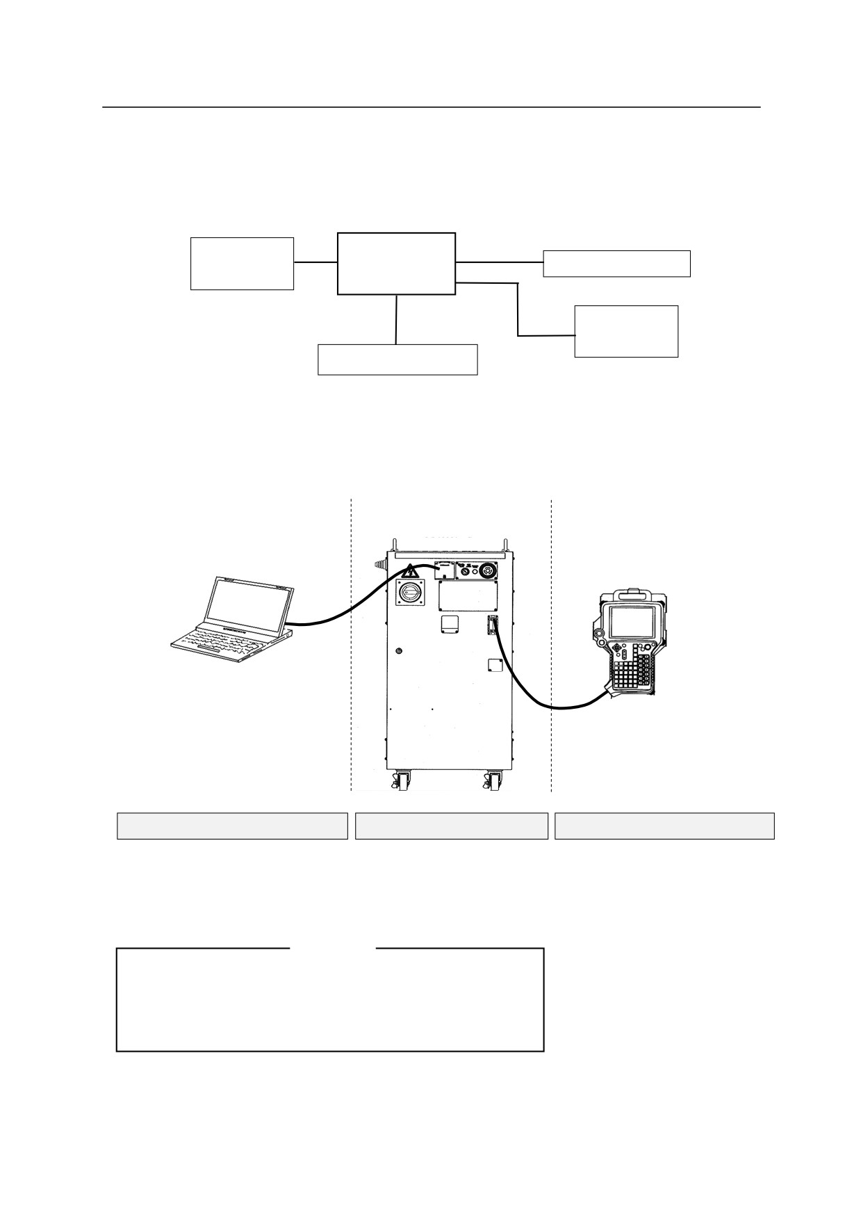
Kawasaki Robot controller E series is composed of following components:
㻌
㻌
E series
Kawasaki
Teach pendant
㻌
Controller
Robot
㻌
㻌
Personal
㻌
Computer
Peripheral Controller
㻌
By connecting a personal computer loaded with the terminal software (KRterm, KCwin32,
KCwinTCP) to a E series controller, the following operations can be done:
䞉 Writing AS commands and instructions
䞉 Saving and loading to and from personal computers
㻌
Personal computer
㻌
㻌
Terminal software
Teach Pendant
(KRterm, KCwin32 , KCwinTCP)
Personal computer
Controller
Teach Pendant
・
Enters AS commands
Daily operations
・Selects program
・
Creates AS programs
・Displays program names and
・Saves/loads programs
steps
・Manually controls the robot
[ NOTE ]
・Monitors signals
Monitor software for PC operates with Microsoft Windows
・Sets repeating conditions
95/98/Me/2000/XP㻌 (for KRterm,Windows 2000/XP/Vista).
・Teaches pose data
Please prepare the appropriate OS.
・Teaches auxiliary data (block
teaching)
1-3
E Series Controller㻌
㻌 㻌 㻌 㻌 㻌 㻌 㻌 㻌 㻌 㻌 㻌 㻌 㻌 㻌 㻌 㻌 㻌 㻌 㻌 㻌 㻌 㻌 㻌 㻌 㻌 㻌 㻌 㻌 㻌 㻌 㻌 㻌 㻌 2. AS System
2.0 AS SYSTEM
This chapter describes the AS system status, AS system switches and system setup.
㻌
2.1 AS SYSTEM STATUS
The AS system consists of the following three modes:
1. Monitor Mode
This is the basic mode in the AS system in which the execution of the AS system is controlled
and monitored. The Monitor commands are executed in this mode. Access to Editor Mode
(by executing EDIT command) or Playback Mode (by executing EXECUTE command) from
this mode.
2. Editor Mode
This mode enables you to create a new program or to modify an existing one. Only editor
commands are executed by the system in this mode.
3. Playback Mode
The system is in Playback Mode during program execution. Commands entered from the
terminal are processed in this mode. At the same time, computations for robot motion control
are performed at a certain cycle. Most monitor commands can be input in this mode. See
5.0 Monitor Commands for monitor commands that are allowed input during Playback Mode.
2-1
E Series Controller㻌
㻌 㻌 㻌 㻌 㻌 㻌 㻌 㻌 㻌 㻌 㻌 㻌 㻌 㻌 㻌 㻌 㻌 㻌 㻌 㻌 㻌 㻌 㻌 㻌 㻌 㻌 㻌 㻌 㻌 㻌 㻌 㻌 㻌 2. AS System
2.2 AS SYSTEM SWITCHES
The following system switches can be set in the AS System using the monitor command
SWITCH. The status and the conditions set for each switch can be checked or changed from the
terminal.
1.
CHECK.HOLD
Determines whether or not to accept input from the keyboard of EXECUTE, DO, STEP,
MSTEP, and CONTINUE commands only in HOLD state.
2.
CP
Enables or disables continuous path movement. When this switch is ON, the robot makes
smooth transitions between motion segments. When it is OFF, the robot decelerates and
stops at the end of each motion segment.
3.
CYCLE.STOP
Determines whether to keep CYCLE START in ON state or to turn it OFF when an external
hold signal is input to stop the motion of the robot.
4.
MESSAGES
Enables or disables message output to the terminal in response to the PRINT or TYPE
command.
5.
OX.PREOUT
Sets the timing for OX signal output in block instructions.
6.
PREFETCH.SIGINS
Determines whether to allow or not the early processing of signal input and output via AS
commands/ instructions.
7.
QTOOL
Determines whether the tool data is changed only when TOOL command/ instruction or block
instruction is executed in repeat mode, or to allow automatic change also in teach mode
according to the tool number taught in block instructions.
8. REP ONCE (Repeat Once)
When this switch is ON, the program runs once. When it is OFF, the program runs
continuously.
2-2
E Series Controller㻌
㻌 㻌 㻌 㻌 㻌 㻌 㻌 㻌 㻌 㻌 㻌 㻌 㻌 㻌 㻌 㻌 㻌 㻌 㻌 㻌 㻌 㻌 㻌 㻌 㻌 㻌 㻌 㻌 㻌 㻌 㻌 㻌 㻌 2. AS System
9. RPS (Random Program Selection)
Enables or disables the function to allow selection of programs via external signals.
10. SCREEN
Enables or disables the scrolling of the screen when the information is too large to fit in one
screen.
11. STP ONCE
Sets whether the program is performed one step at a time or continuously.
Refer to 5.6 Monitor Command SWITCH, ON, OFF for further information on how to set the
system switches.
2-3
E Series Controller㻌
㻌 㻌 㻌 㻌 㻌 㻌 㻌 㻌 㻌 㻌 㻌 㻌 㻌 㻌 㻌 㻌 㻌 㻌 㻌 㻌 㻌 㻌 㻌 㻌 㻌 㻌 㻌 㻌 㻌 㻌 㻌 㻌 㻌 2. AS System
2.3 AS SYSTEM SETUP
The following system settings can be changed depending on the need, using the monitor
commands.
1.
Zeroing (ZZERO command)
ZZERO command is used to set the encoder value corresponding to the mechanical origin of
each axis of a robot as zeroing data. When replacing the servo motor or performing
maintenance on an encoder, the encoder value will need adjustment using this command.
(This command is for maintenance purposes only.)
2.
Clamp setting (HSETCLAMP command)
This setting is made prior to shipment from the factory. The settings, single/double and
output spec (ON when closed /OFF when closed), can be changed using HSETCLAMP
command. However, the change will only affect the software, so be sure to check the
consistency with the hardware.
3.
Maximum number of input and output signals (ZSIGSPEC command)
ZSIGSPEC command sets the maximum number of input and output signals that can be used.
It is set prior to shipment from the factory. (This is a default setting that functions as a
software error check, thus be sure it is consistent with the hardware.)
4.
Software Dedicated Signals (DEFSIG command)
In addition to the hardware dedicated signals,㻌 there are I/O signals in the software that can be
used as dedicated signals (Software dedicated signals). The signals in the table below can be
used as Software dedicated signals. Note that since the number of I/O signals in the
software is the sum of Software dedicated signals and general purpose signals, the number of
general purpose signal decreases as more software dedicated signals are used.㻌 㻌 Please refer
to External I/O Manual for details of dedicated signals.
2-4

E Series Controller㻌
㻌 㻌 㻌 㻌 㻌 㻌 㻌 㻌 㻌 㻌 㻌 㻌 㻌 㻌 㻌 㻌 㻌 㻌 㻌 㻌 㻌 㻌 㻌 㻌 㻌 㻌 㻌 㻌 㻌 㻌 㻌 㻌 㻌 2. AS System
Software Dedicated Input Signal
Software Dedicated Output Signal
EXT. MOTOR ON
MOTOR_ON
EXT. ERROR RESET
ERROR
EXT. CYCLE START
AUTOMATIC
EXT. PROGRAM RESET
CYCLE START
Ext. prog. select (JUMP_ON, JUMP_OFF
TEACH MODE
RPS_ON, RPSxx)
HOME1, HOME2
EXT_IT
POWER ON
EXT. SLOW REPEAT MODE
RGSO
Ext. prog. select enable (RPS)
Ext. prog. select (JMP_ST, RPS_ST)㻌
2-5
E Series Controller㻌
㻌 㻌 㻌 㻌 㻌 㻌 㻌 㻌 㻌 㻌 㻌 㻌 㻌 㻌 㻌 㻌 㻌 㻌 㻌 㻌 㻌 㻌 㻌 㻌 㻌 㻌 㻌 㻌 㻌 㻌 㻌 㻌 㻌 2. AS System
2.4 INPUT/OUTPUT CONTROL
㻌
2.4.1 TERMINAL CONTROL
Data and commands input at a terminal are first received by the system buffer. Then they are
read by the monitor or program and echoed or displayed on the terminal screen. The maximum
number of characters that can be input at a terminal is 128, and additional characters input are
ignored.
Output of data to a terminal can be controlled using the PRINT and TYPE instructions.
8 bits
are displayed on the terminal screen. Unless format is specified using specification code “/S”
with the PRINT/TYPE instruction, data are displayed with a new line starting after each
command. (See 6.8 Message Control Instructions for detailed information.)
Terminal input and output can be controlled using the commands shown below. These are
called terminal control commands.
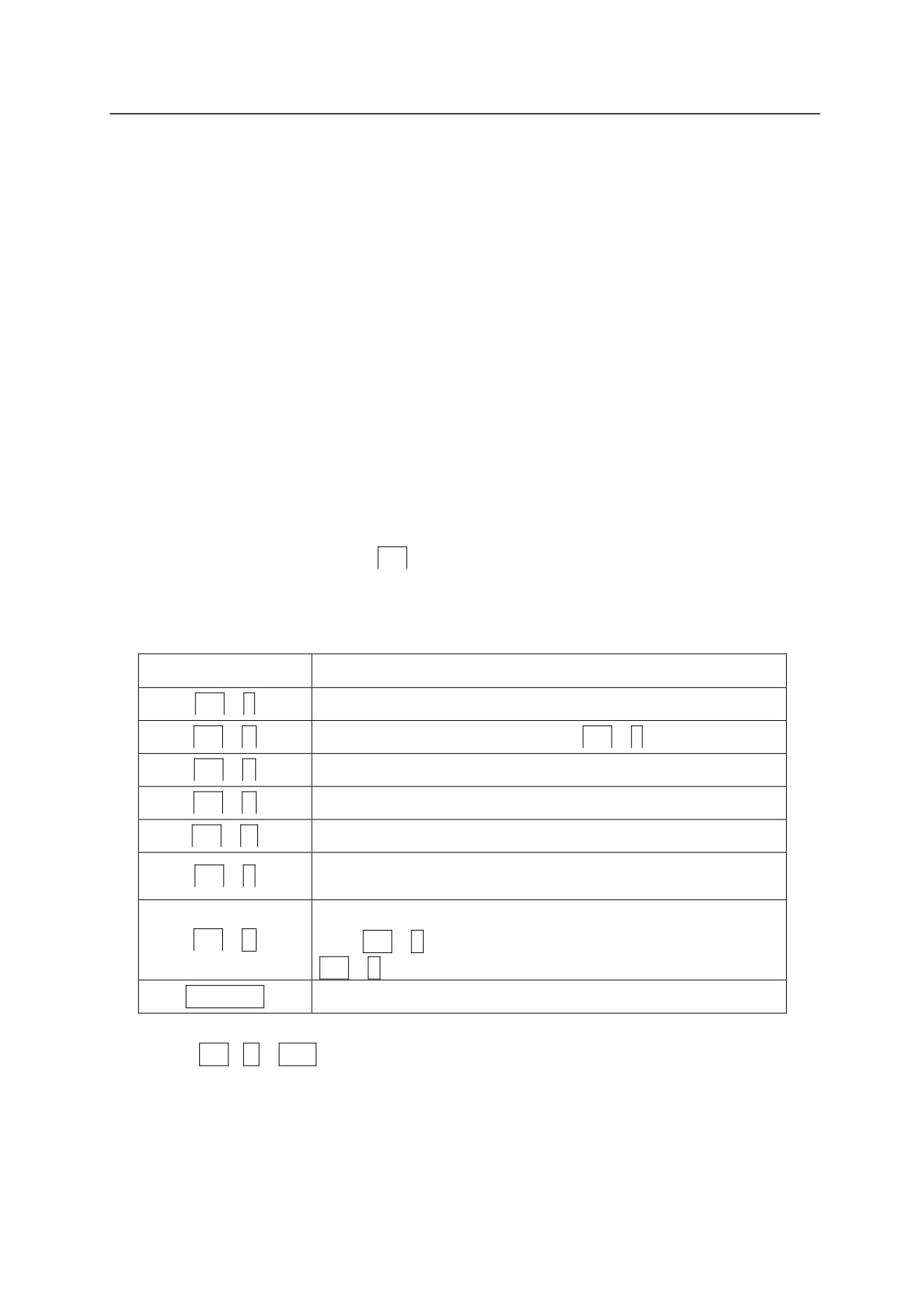
Ctrl (Control Key) is pressed with each alphabetical
character (the character may be either lower or upper case letters). Unlike other AS commands,
there is no need to press the ENTER key after these command.
Commands
Functions
Ctrl +
S
Stops the scrolling of the display terminal.
Ctrl +
Q
Resumes the data output stopped by
Ctrl +
S .
Ctrl +
C
Cancels the last input line.
Ctrl +
H
Deletes the last input character. (Backspace)
Ctrl +
M
Ends the input of the current line.
Displays the content of the line entered previously on the
Ctrl +
L
current input line. It can be used up to seven times. (Last)
Displays the content of the line input after the line displayed
Ctrl +
N
using
Ctrl +
L. This operation can be used only after
Ctrl +
L is used more than once. (Next)
Backspace
Deletes the last input character.
Input TAB (Ctrl + I
or
TAB) as space (blank).
2-6
E Series Controller㻌
㻌 㻌 㻌 㻌 㻌 㻌 㻌 㻌 㻌 㻌 㻌 㻌 㻌 㻌 㻌 㻌 㻌 㻌 㻌 㻌 㻌 㻌 㻌 㻌 㻌 㻌 㻌 㻌 㻌 㻌 㻌 㻌 㻌 2. AS System
2.4.2 EXTERNAL MEMORY DEVICES
The commands below are used to save programs, variables and pose information in the robot
memory, USB flash drive memory, or computer hard disk.
1. Displays the contents on the USB flash drive memory. (USB_FDIR)
2. Saves the data on the robot memory to PC or USB flash drive files. (SAVE䠆, USB_SAVE)
3. Loads the data on PC or USB flash drive to the robot memory. (LOAD, USB_LOAD)
4. Deletes the files on PC or USB flash drive. (USB_FDEL)
Commands with USB_ refer to USB flash drive memory.
Note䠆㻌 㻌 SAVE/ LOAD command may be used only when the computer is connected.
See also 5.2 Program and Data Control Commands, 5.3 Program and Data Storage Commands
2-7

E Series Controller㻌
㻌 㻌 㻌 㻌 㻌 㻌 㻌 㻌 㻌 㻌 㻌 㻌 㻌 㻌 㻌 㻌 㻌 㻌 㻌 㻌 㻌 㻌 㻌 㻌 㻌 㻌 㻌 㻌 㻌 㻌 㻌 㻌 㻌 2. AS System
2.5 INSTALLING TERMINAL SOFTWARE
The robot can be controlled from a personal computer using the AS language. To do so, load
KRterm, KCwin32 or KCwinTCP terminal software on to a PC and connect the PC to E series
controller. The operation environment needed for each of the software is as follows:
Hardware
Microsoft Windows running PC with 80486 or higher CPU
KCwin32/KCwinTCP
Microsoft Windows 95/98/NT4.0/2000/XP
OS
KRterm
Microsoft Windows 2000/XP/Vista/7/8/8.1
KCwin32/KCwinTCP
Toshiba Personal Computer Dynabook Satellite 2520 (Windows98)
Compaq Armada 1500C (Windows98)
IBM ThinkPad 365X (Windows95)
Tested
KRterm
models
DELL Inspiron 8000 (Windows2000)
Lenovo ThinkCentre (WindowXP)
Gateway GT5228J (Windows Vista)
NEC Mate, Panasonic CF(Windows 7)
Note* The software may not operate properly on untested models.
Connecting the computer and the controller using the RS-232C cable enables a single computer
to control a single robot. An Ethernet connection enables multiple computers to control multiple
robots.
Follow the below procedure to install the terminal software on to the PC.
2-8
E Series Controller㻌
㻌 㻌 㻌 㻌 㻌 㻌 㻌 㻌 㻌 㻌 㻌 㻌 㻌 㻌 㻌 㻌 㻌 㻌 㻌 㻌 㻌 㻌 㻌 㻌 㻌 㻌 㻌 㻌 㻌 㻌 㻌 㻌 㻌 2. AS System
2.5.1 INSTALLING KCWIN32/KCWINTCP
Install by copying the KCwin32/KCwinTCP software, provided by Kawasaki, to a file on a
Windows PC. After the installation is completed, an icon for KCwin32/KCwinTCP is created,
so double-click on it. KCwin32/KCwinTCP starts and the window as shown below is
displayed.
2.5.2 INSTALLING KRTERM
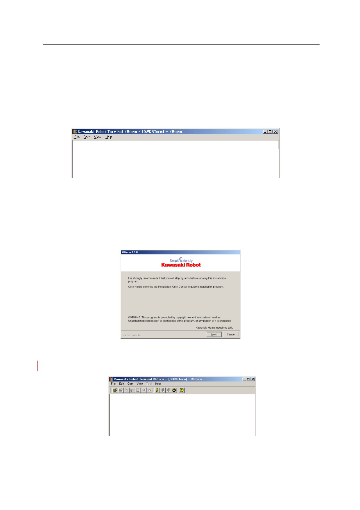
Copy the setup software for KRterm (SetupE.exe), provided by Kawasaki to a file on a Windows
PC and execute it. Follow the installer direction to complete the installation.
After the installation is completed, an icon for KRterm is created, so double-click on it. KRterm
starts and the window as shown below is displayed.
2-9
E Series Controller㻌
㻌 㻌 㻌 㻌 㻌 㻌 㻌 㻌 㻌 㻌 㻌 㻌 㻌 㻌 㻌 㻌 㻌 㻌 㻌 㻌 㻌 㻌 㻌 㻌 㻌 㻌 㻌 㻌 㻌 㻌 㻌 㻌 㻌 2. AS System
2.6 OPERATIONS FROM PERSONAL COMPUTER
2.6.1 SYSTEM SETUP
2.6.1.1 CONNECTING TO RS-232C PORT
The operation of the controller from a PC via RS-232C is possible by using KRterm or KCwin32
software.
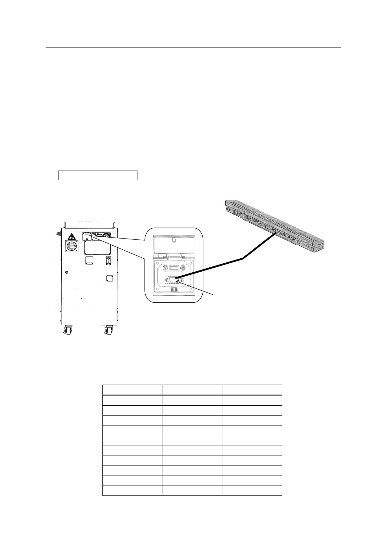
1. Connect the personal computer with the controller using the RS-232C cable. Make sure the
CONTROLLER POWER on the controller and the computer power are both turn off.
PC with built-in
RS-232C port
RS-232C
㻌
㻌
For PC connection cable, use straight cable with female- female Dsub9 pin connector. The
connectors are allocated as below:
Pin
Name
Content
1
CD
Carrier detection
2
RD
Receive data
3
SD
Send data
4
ER
Data terminal
ready
5
SG
Ground
6
DR
Data set ready
7
RS
Request send
8
CS
Send allowed
9
CI
Calling indicate
2-10
E Series Controller㻌
㻌 㻌 㻌 㻌 㻌 㻌 㻌 㻌 㻌 㻌 㻌 㻌 㻌 㻌 㻌 㻌 㻌 㻌 㻌 㻌 㻌 㻌 㻌 㻌 㻌 㻌 㻌 㻌 㻌 㻌 㻌 㻌 㻌 2. AS System
2. Turn on the computer, and start the terminal software by clicking on the icon.
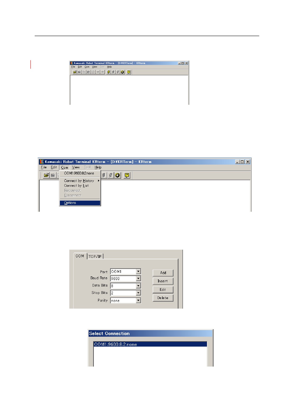
3.㻌 When the screen of the terminal software opens, set the connection. Select from the menu bar,
[Com(munication)] [Options].
Enter 9600 for <Baudrate>, 8 for <Data Bits>, 2 for <Stop Bits>, “none” for <Parity>. For
KRterm, select the <COM> tab and similarly set the parameters, then click <OK>.
Next, select [Com(munication)]䊻[Connect by List] and in the window that appears, select
the connection set above. Click <OK>.
2-11
E Series Controller㻌
㻌 㻌 㻌 㻌 㻌 㻌 㻌 㻌 㻌 㻌 㻌 㻌 㻌 㻌 㻌 㻌 㻌 㻌 㻌 㻌 㻌 㻌 㻌 㻌 㻌 㻌 㻌 㻌 㻌 㻌 㻌 㻌 㻌 2. AS System
5. Turn ON the
CONTROLLER POWER on the controller.㻌
(See “Operation Manual”㻌 3.1㻌 Power ON Procedure).
6.㻌 The initial screen the software will appear on the display.
When the
CONTROLLER POWER is turned ON before connecting the PC to the controller,
only the prompt “>” will appear and not the initial screen. However, the software works the
same.
2-12
E Series Controller㻌
㻌 㻌 㻌 㻌 㻌 㻌 㻌 㻌 㻌 㻌 㻌 㻌 㻌 㻌 㻌 㻌 㻌 㻌 㻌 㻌 㻌 㻌 㻌 㻌 㻌 㻌 㻌 㻌 㻌 㻌 㻌 㻌 㻌 2. AS System
2.6.1.2 CONNECTING ROBOTS USING THE ETHERNET
The operation of the controller from a PC via ETHERNET is possible by using KRterm or
KCwinTCP software.
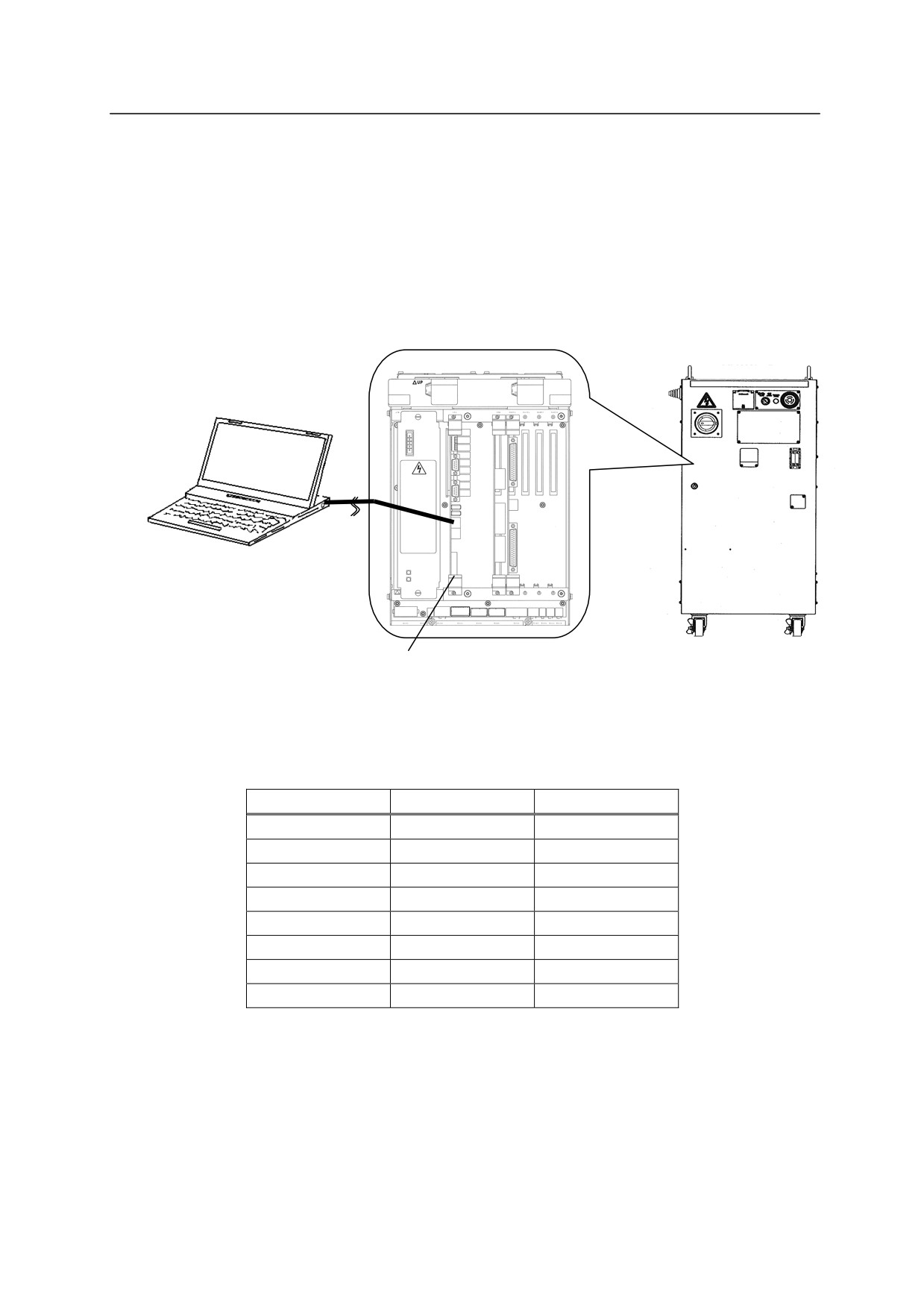
1. Connecting the cables.
㻌㻌
㻌
r
㻌
㻌
㻌
㻌
㻌
㻌
㻌
ETHERNET connector
㻌
on personal computer
㻌
㻌
1TA/1VA board
㻌
Front view of the controller
㻌
For ETHERNET cable, use straight cable with RJ45 connector.
The connectors are allocated as
below:
Pin
Name
Content
1
TD+
Send+
2
TD-
Send-
3
RD+
Receive+
4
Not used
5
Not used
6
RD-
Receive-
7
Not used
8
Not used
㻌
2. Turn ON the PC and double click on the icon for the terminal software.
2-13
E Series Controller㻌
㻌 㻌 㻌 㻌 㻌 㻌 㻌 㻌 㻌 㻌 㻌 㻌 㻌 㻌 㻌 㻌 㻌 㻌 㻌 㻌 㻌 㻌 㻌 㻌 㻌 㻌 㻌 㻌 㻌 㻌 㻌 㻌 㻌 2. AS System
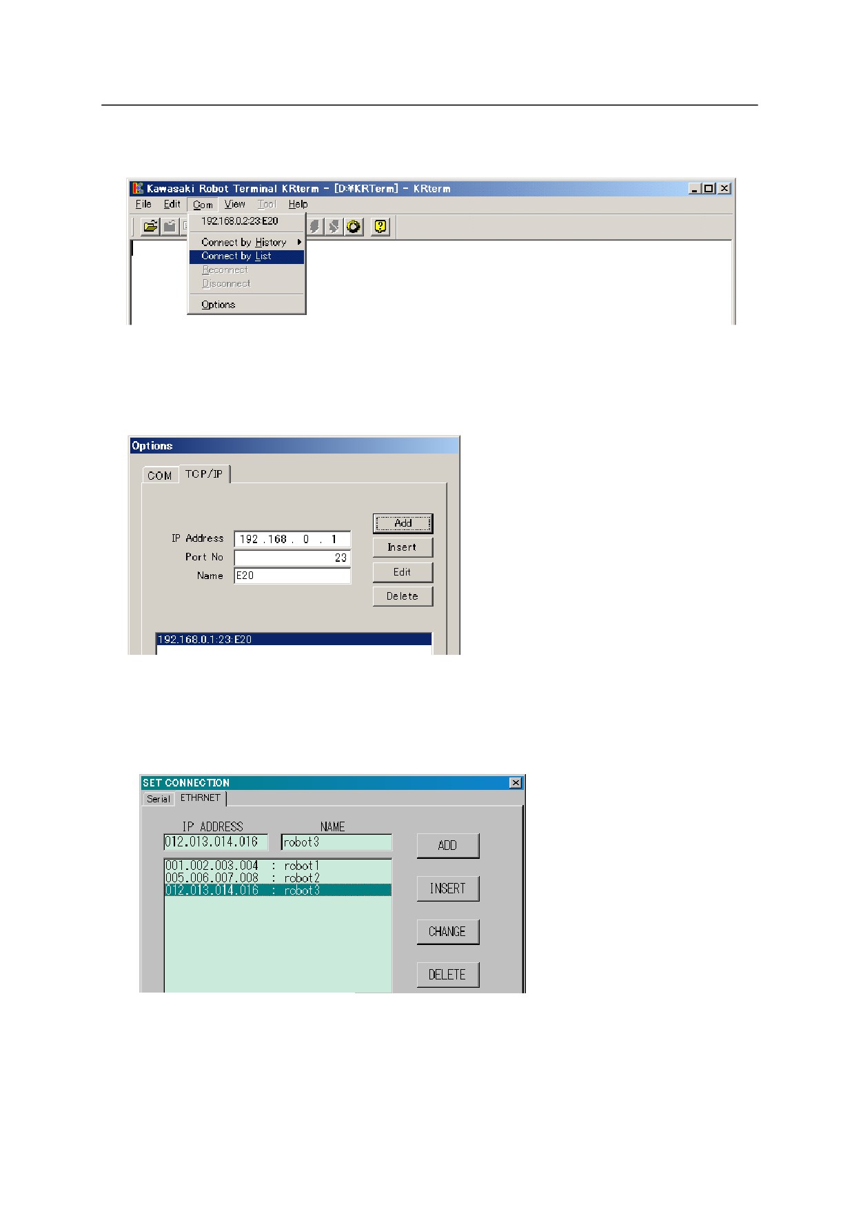
3. Next, register the IP address for the robot to connect.
Select [Com(munication)] [Options] from the menu bar.
For KRterm, click on [TCP/IP] tab and enter the IP address and name (optional) for the
robot controller to connect on the network. Click on <Add>.
For KCwinTCP the screen looks as shown below. Enter the IP address and name (optional)
for the robot controller to connect on the network, and then click on <Add>.
㻌 㻌 㻌
4.
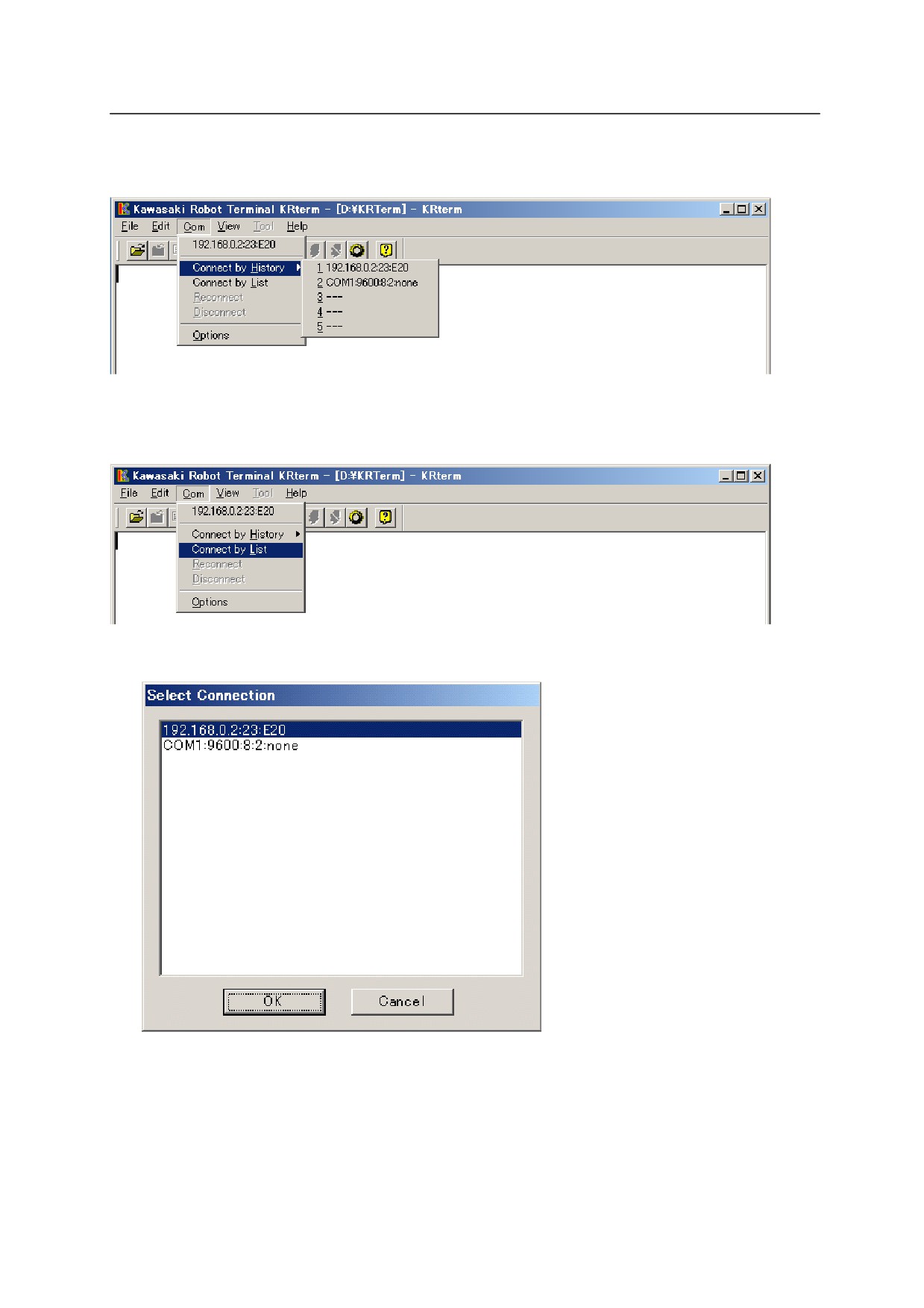
Connect to the registered robot on the network.
(1) The robot last used is displayed at the top of the drop-down list that is displayed when
clicking on [Com] on the menu bars. OR
2-14
E Series Controller㻌
㻌 㻌 㻌 㻌 㻌 㻌 㻌 㻌 㻌 㻌 㻌 㻌 㻌 㻌 㻌 㻌 㻌 㻌 㻌 㻌 㻌 㻌 㻌 㻌 㻌 㻌 㻌 㻌 㻌 㻌 㻌 㻌 㻌 2. AS System
(2) Select [Com] [Connect by History] to displayed a list of robots used in the past.
Select the robot to connect from this list.
㻌
(3) To connect to robots not in the list, select [Com(C)] [Connect by List].
Select the robot to connect and click on <OK>.
5. If the connection is established, robot information such as its name followed by the message
login : . Enter “as” after this message. A prompt “>” returned from the robot is then
displayed.
AS commands can be input once the prompt appears.
2-15
E Series Controller㻌
㻌 㻌 㻌 㻌 㻌 㻌 㻌 㻌 㻌 㻌 㻌 㻌 㻌 㻌 㻌 㻌 㻌 㻌 㻌 㻌 㻌 㻌 㻌 㻌 㻌 㻌 㻌 㻌 㻌 㻌 㻌 㻌 㻌 2. AS System
2.6.2 UPLOADING AND DOWNLOADING DATA
(1)㻌 SAVE command
To save the data on the computer, use the SAVE command (See 5.3㻌 SAVE command).
Example
>SAVE test.pg
This saves the data in the same directory as
the KRterm(KCwin32/KCwinTCP) in the
computer hard disk.
㻌 㻌
>SAVE My Documents¥ test.pg㻌 㻌 This saves the data in the specified file.
(2)㻌 LOAD command
To load data from the computer to the robot memory, use the LOAD command.
Example
>LOAD data01.as
2.6.3 SYSTEM SHUTDOWN
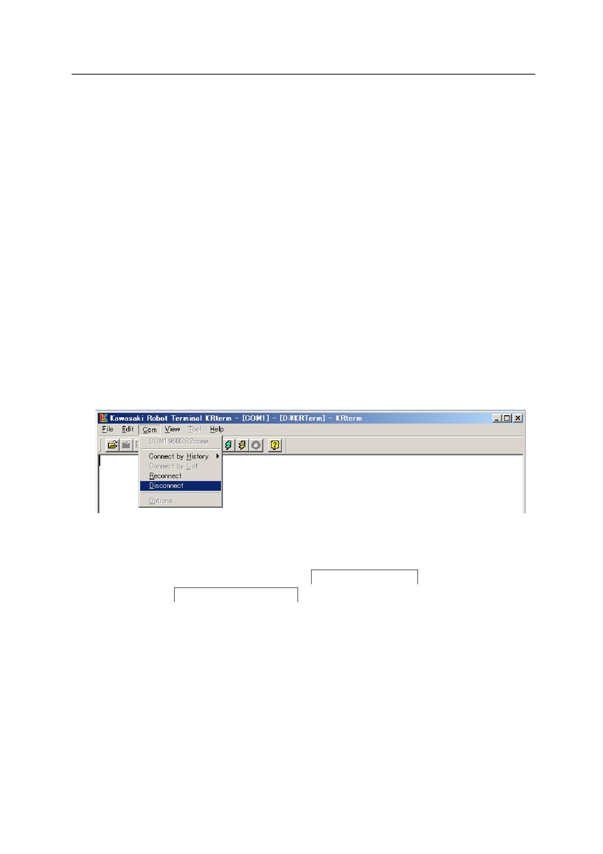
1. When the robot is connected, choose from the menu bar [Com(munication)]
[Disconnect] to disconnect the robot.
2. Turn off the robot controller. (See “ Operation Manual”㻌 3.2㻌 POWER OFF procedure).㻌 㻌
(1) Change HOLD/RUN state from RUN to HOLD.
(2) Turn OFF the motor power by pressing the
EMERGENCY STOP button.
(3) Turn OFF the
CONTROLLER POWER.
2-16
E Series Controller㻌
㻌 㻌 㻌 㻌 㻌 㻌 㻌 㻌 㻌 㻌 㻌 㻌 㻌 㻌 㻌 㻌 㻌 㻌 㻌 㻌 㻌 㻌 㻌 㻌 㻌 㻌 㻌 㻌 㻌 㻌 㻌 㻌 㻌 2. AS System
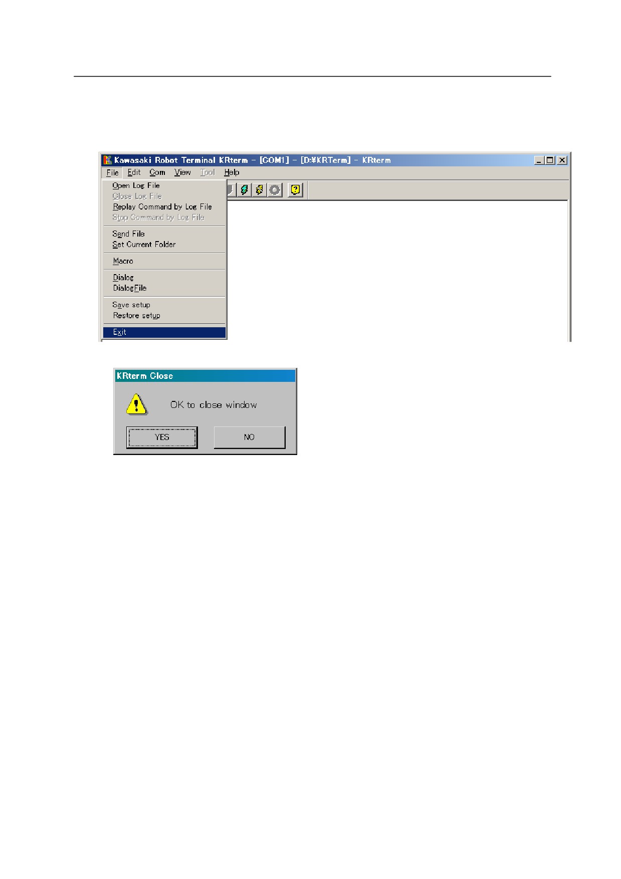
3. Shut down the terminal software.
(1) Choose from the menu bar [File] [Exit].
㻌 㻌
(2)㻌 Click <YES>.
4. Shut down the computer.
5. If there is no need to keep the computer connected to the controller, disconnect the cable.
Make sure the controller and the computer power are both turned off before disconnecting.
2-17
E Series Controller㻌
㻌 㻌 㻌 㻌 㻌 㻌 㻌 㻌 㻌 㻌 㻌 㻌 㻌 㻌 㻌 㻌 㻌 㻌 㻌 㻌 㻌 㻌 㻌 㻌 㻌 㻌 㻌 㻌 㻌 㻌 㻌 㻌 㻌 2. AS System
2.6.4 USEFUL FUNCTIONS OF KRTERM
2.6.4.1 CREATING LOGFILES
The contents displayed on the KRterm screen can be saved as a log file. This is useful when
making printout of the robot operation procedures.
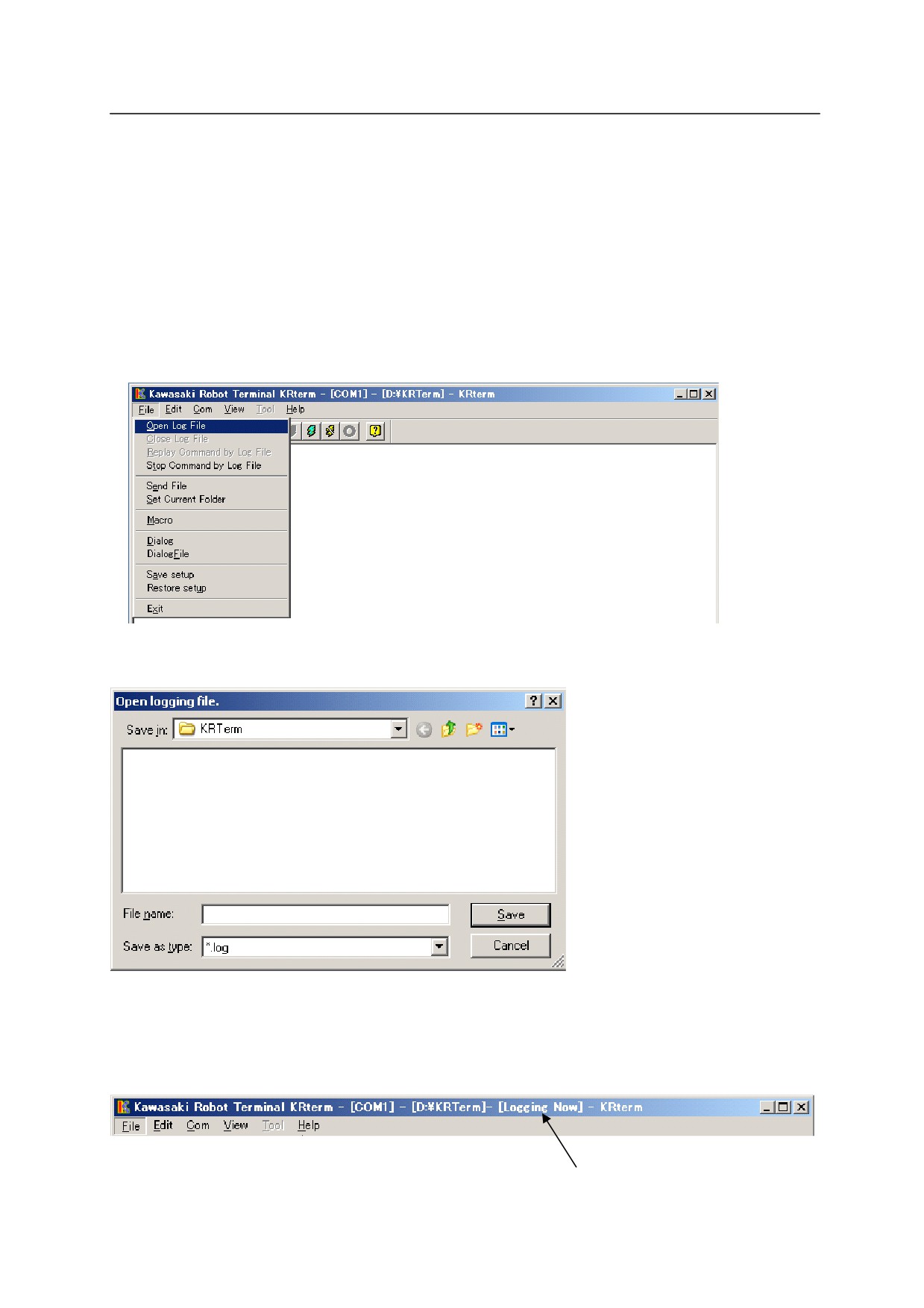
1. Start logging.
(1) Choose from the menu bar [File] [Open Log File].
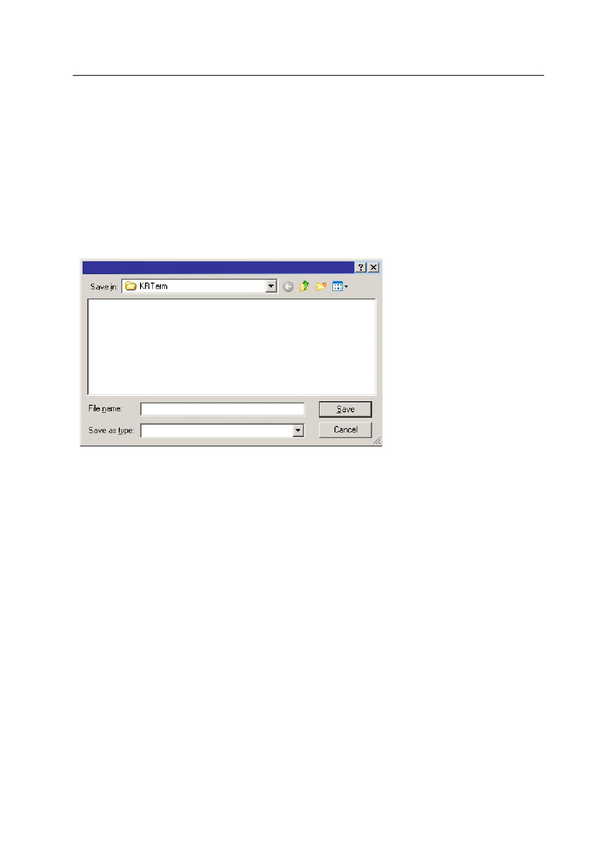
(2) Select the folder to save the log file, and name the file.㻌
㻌
㻌
(3)㻌 The message [Logging Now] appears on the title bar. The contents on the display are
recorded until the log file is closed.
㻌
㻌
The contents on the display are recorded while this message is shown.
㻌
2-18
E Series Controller㻌
㻌 㻌 㻌 㻌 㻌 㻌 㻌 㻌 㻌 㻌 㻌 㻌 㻌 㻌 㻌 㻌 㻌 㻌 㻌 㻌 㻌 㻌 㻌 㻌 㻌 㻌 㻌 㻌 㻌 㻌 㻌 㻌 㻌 2. AS System
2.㻌 End log㻌
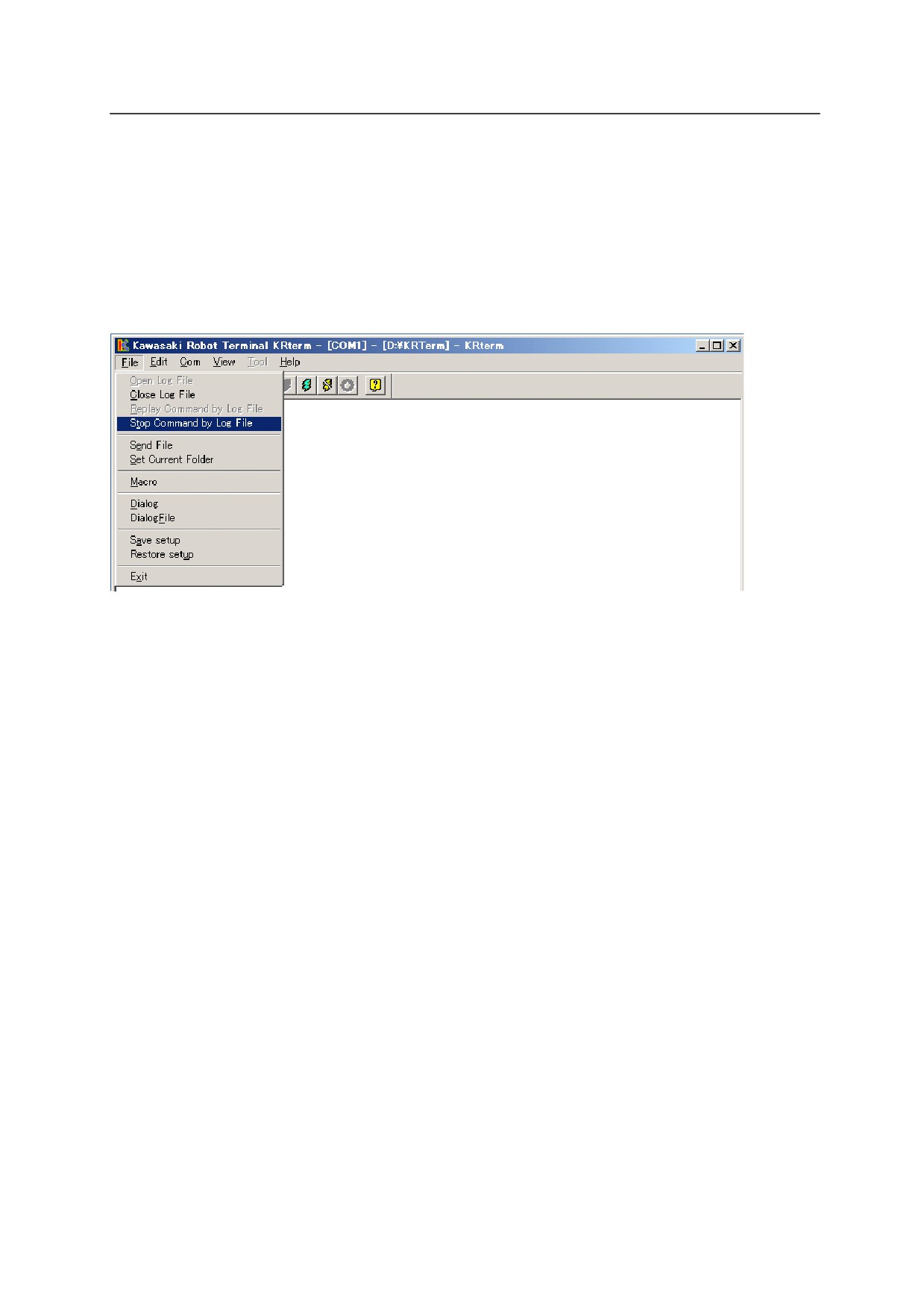
Once logging starts, all the contents on the KRterm display will be recorded until the log file is
closed.㻌
㻌
To close the log file and end log, choose from the menu bar [File]
[Stop Command by Log File].
2-19
E Series Controller㻌
㻌 㻌 㻌 㻌 㻌 㻌 㻌 㻌 㻌 㻌 㻌 㻌 㻌 㻌 㻌 㻌 㻌 㻌 㻌 㻌 㻌 㻌 㻌 㻌 㻌 㻌 㻌 㻌 㻌 㻌 㻌 㻌 㻌 2. AS System
2.6.4.2 MACRO FUNCTIONS
Macro functions are provided in KRterm and KCwin32/KCwinTCP systems. If a task needs to
be executed repeatedly, recording the series of instructions/commands for that task inside a macro
can be very useful and will increase efficiency.
To record a macro, choose from the menu bar [FILE (F)] [MACRO (M)] and enter the file
name to save that macro. To run a macro, use the SEND command on the KRterm screen.
Open Macro file
aaa.uas
*.uas
See Help in KRterm or KCwin32/KCwinTCP for more details.
㻌 㻌 㻌
2-20
///////////////////////////////////////