Kawasaki Robot Controller E Series. Reference Manual (2015) - page 2
3. Information Expressions in AS Language
3.0 INFORMATION EXPRESSIONS IN AS LANGUAGE
This chapter describes the types of information and variables used in AS language.
3.1 NOTATION AND CONVENTIONS
1.
Uppercase and lowercase letters
For easier understanding, the following rules apply to the usage of upper and the lowercase
letters in this manual. All AS keywords (commands, instructions, etc) are shown in
uppercase. Variables and any other items that can be specified are shown in lowercase.
However, both can be used when entering at an AS terminal.
2.
Keys and switches
The keys on the teach pendant or the computer keyboard and the switches on the controller
are expressed in this manual with their names surrounded by a
Example
Backspace,
CONTROLLER POWER
3.
Abbreviations
Keywords can be abbreviated. For example, EXECUTE command can be abbreviated as
EX. See Appendix 5 AS Language List.
4.
Space, Tab
At least one blank space or tab is necessary as a delimiter between the command (or
instruction) and the parameter*. Also, a space or tab is necessary between those parameters
not divided by commas or other delimiters. Excess spaces or tabs are ignored by the system.
Note* A parameter is a data necessary for completing commands or other functions.
For example, in SPEED command, parameter data is needed for specifying the
robot speed. When the command or function uses several parameters, a comma or
a space separates each parameter.
Example SPEED
50
5.
ENTER key
Monitor commands and program instructions are processed by pressing the
ENTER key.
In this manual, the
ENTER key is shown as
.
6.
Omitted Parameters
Many monitor commands and program instructions have parameters that can be omitted. If
there is a comma after these optional parameters, the comma should be retained even if the
3-1

3. Information Expressions in AS Language
parameter is omitted. If all successive parameters are omitted, comma may also be omitted.
7. Numeric values
Values are expressed in decimal notations, unless noted otherwise. Mathematical
expressions can be used to designate these values as parameters in AS monitor commands and
program instructions. However, note that acceptable values are restricted. The following
rules show how the values are interpreted in various cases.
(1) Distance
Used to define the length the robot moves between two points. The unit for distance is
millimeter (mm); the unit is omitted when entering. The input values can be either negative
or positive.
(2) Angles
Describes the tool orientation and axis value by Euler’s 3 angles and rotation angle of a robot
joint, respectively. The values can be negative or positive, with the maximum angles limited
to 180 degrees or 360 degrees, depending on the commands used.
(3) Scalar variables
Unless noted otherwise, these variables represent real values. The values for the variables
can range from 3.4E38 to 3.4E38 (3.4×1038 to 3.41038). When it exceeds 999999, it
is expressed as xE+y (x is the mantissa, y is an exponent).
(4) Joint number
Expresses the joints of the robot in integer from 1 to the number of joints available (standard
type has 6 joints). The joints are numbered in order starting from the base joint.
(Usually
expressed JT1, JT2
).
(5) Signal number
Identifies binary (ON/OFF) signals. The values are given as integers and take the following
ranges.
Standard range
Maximum range
External output signal
1 32
1 960
External input signal
1001 1032
1001 1960
Internal signal
2001 2256
2001 2960
Negative signal numbers indicate OFF state.
3-2
3. Information Expressions in AS Language
8. Keywords
Generally, variable names can be freely assigned within the AS system. However,
keywords defining commands, instructions, etc. in the AS system are reserved, and cannot be
used to name pose data, variables, etc.
3-3
3. Information Expressions in AS Language
3.2 POSE INFORMATION, NUMERIC INFORMATION, CHARACTER INFORMATION
There are three types of information in the AS system: pose* information, numeric information,
and character information.
Note*
“Pose” was formerly called “location”, but in accordance with the international standards
(the ISO), in this manual, it is referred to as pose to express both the position and the
orientation of the robot in one word.
3.2.1 POSE INFORMATION
Pose information is used to specify the position and orientation of the robot in the given working
area. The robot’s position and orientation refer to the position of the tool center point (TCP) and
orientation of the tool (coordinates), unless otherwise specified. The position and orientation
together is called the pose of a robot.
The pose is determined by where the robot is and which way it is facing, therefore, when a robot
is instructed to move, these two things are done at the same time:
1. Robot’s TCP moves to the specified position.
2. Robot’s tool coordinates rotate to the specified orientation.
The pose data is described by a set of joint displacement values or by transformation value:
1. Joint displacement values
This pose information is given by a set of angular or linear displacement values from each of
the robot axes origins. Using encoder values, angular displacement and linear displacement
are calculated and described in degrees and millimeters, respectively. Once the joint
displacement values are determined, the position and orientation of the TCP is uniquely
specified.
Example The joints are expressed in order from JT1,…JT6, and the displacement value of
each joint is shown beneath the joint number.
JT1 JT2
JT3
JT4 JT5 JT6
#pose = 0.00,
33.00,
-15.00,
0,
-40,
30
2. Transformation values (X,Y,Z,O,A,T)
Describes a pose of coordinates in relation with reference coordinates. Unless specified
otherwise, it refers to the transformation values of the tool coordinates relative to the base
3-4
3. Information Expressions in AS Language
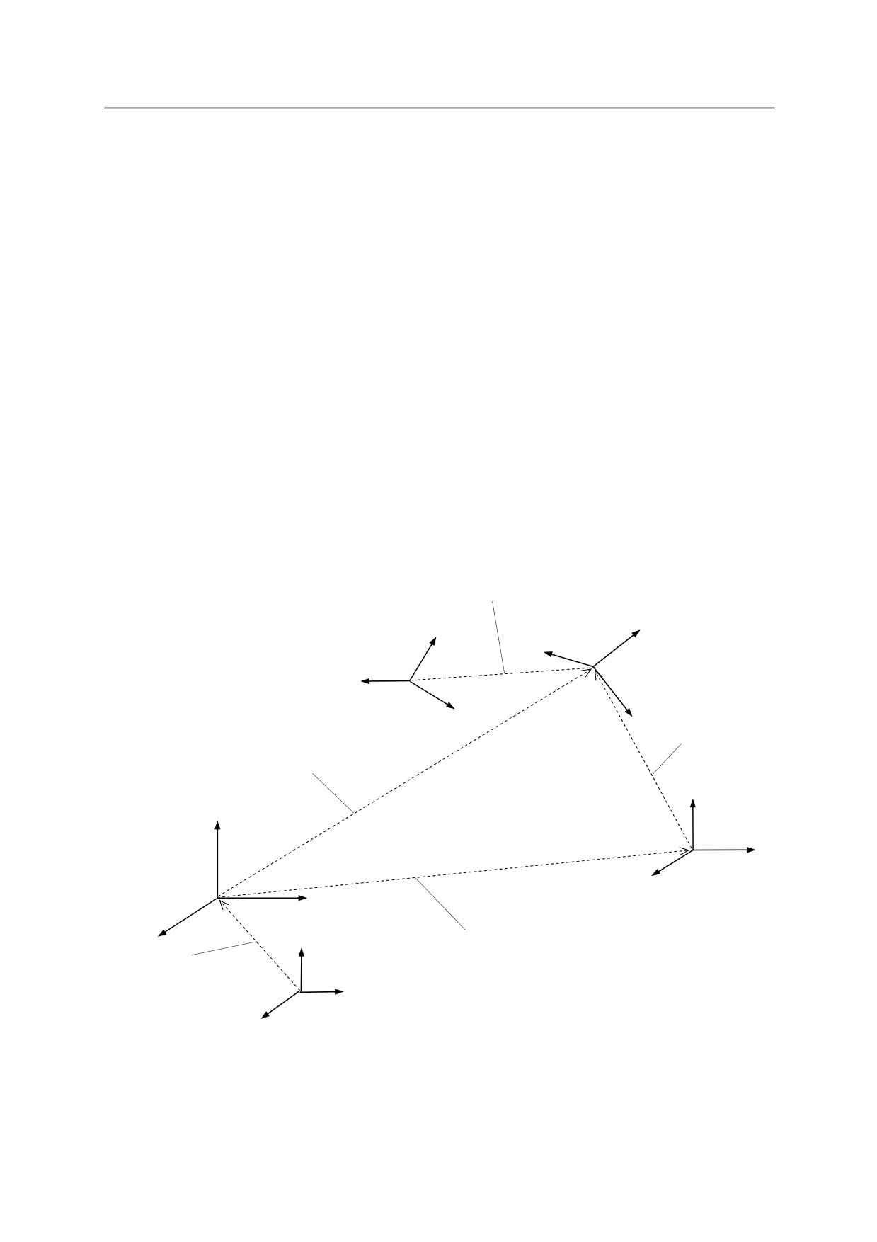
coordinates of a robot. The position is given by the XYZ values of the TCP on the base
coordinates, and the orientation is given by Euler’s OAT angles* of the tool coordinates in
respect with the base coordinates. Some of the commonly used transformation values are: the
tool transformation values, describing the pose of the tool coordinates relative to the null tool
coordinates, and workpiece transformation values, describing the pose of the tool coordinates
relative to the workpiece coordinates.
Note* See Appendix 3 Euler’s O,A,T Angles.
Example
X Y
Z O A T
pose =
0,
1434,
300,
0,
0,
0
If the robot has more than six axes, the value of the extra axis is shown with the transformation
values.
Example
X Y
Z O A T JT7
pose =
0,
1434,
300,
0,
0,
0
1000
Tool transformation values
zt1
zt
xt1
Null tool coordinates*
Tool coordinates
xt
Workpiece
yt1
yt
transformation values
Transformation values
zw
Base coordinates
zb1
yw
xw
Workpiece coordinates
yb1
Workpiece transformation
xb1
zb
values
Base transformation
values
yb
xb
Null base coordinates**
Note *
Null tool coordinates have their origin at the center of the robot’s tool mounting
flange surface, and they are described by the tool transformation values
(0,0,0,0,0,0).
3-5

3. Information Expressions in AS Language
Note** Null base coordinates are set as the robot’s default value, and are described by the
base transformation values (0,0,0,0,0,0).
The joint displacement values and the transformation values have advantages and
disadvantages. Use them to suit your need.
Joint displacement values
Transformation values
· Playback precision is achieved and
· The tool coordinates origin used in
there is no ambiguity about robot
repeat mode does not change even if
configuration at a pose
the tool is changed. (The null tool
coordinates shift)
Advantage
· Can use relative coordinates. (e.g.
workpiece coordinates)
· Convenient for processing as the data
are shown in XYZOAT values.
· TCP changes when the tool is
· Coordinates will change according to
changed (null tool coordinates
base or tool transformation values, so a
remain the same)
full understanding is needed of the
Disadvantage
· Cannot use relative coordinates (e.g.
effect of any change for safe usage.
workpiece coordinates, etc.)
· Robot configuration may change if it is
not set before repeating movements.
· Setting the starting pose of a
· Describing relative coordinates such as
program
workpiece coordinates
· Setting the robot configuration at or
· Describing a pose that is to be changed
Suggested
just before a pose described by
using numeric values with functions
usage
transformation values
such as SHIFT
· Use for other common poses
· Describing a pose that is to be changed
by sensor information
3-6
3. Information Expressions in AS Language
[ NOTE ]
1. Unlike at a pose defined by joint displacement values, where the robot configuration is set
uniquely, when a pose is defined by transformation values, the robot may take different
configurations with respect to that pose. It is because transformation values only set the
XYZOAT values of the tool coordinates of the robot and do not define the axis value of
each joint. Therefore, before starting the robot in repeat mode, be sure to fix the robot’s
configuration using configuration commands (LEFTY, etc.) or by recording the joint
displacement values.
2. Since transformation values are described by the base coordinates, if the base coordinates
are shifted using the BASE command/instruction, the robot’s TCP will also be shifted the
same amount. This is one of the advantages of using the transformation values, but pay
attention to the effect that changing the base coordinates will have on transformed points.
Failure to do so may cause accidents such as interference with peripheral devices.
Take the same caution when using the TOOL command/instruction.
3.2.2 NUMERIC INFORMATION
In the AS system, numeric values and expressions can be used as numeric information. A
numeric expression is a value expressed by using numerals and variables combined with
operators and functions. Numeric expressions are used not only for mathematical calculations,
but also as parameters for monitor commands and program instructions.
For example in the DRIVE command, three parameters, joint number, motion amount, and speed,
are specified. The parameters can be expressed either in numeric values or in expressions as in
the following example:
DRIVE 3,45,75
Moves joint number 3 by 45° at the speed of 75 %.
DRIVE joint, (start+30)/2, 75
When specified joint=2, start=30 then joint 2 moves by
+30° at 75 % speed.
Numeric values used in AS system are divided into three types:
1. Real numbers
Real numbers can have both integers and fractions. It can be a positive or a negative value
between 3.4 E+38 and 3.4 E+38(3.41038 and 3.41038) or zero. Real numbers can be
represented in scientific notations. The symbol E divides between the mantissa and the
exponent. The exponent may either be negative (power of 1/10) or positive (power of 10).
3-7
3. Information Expressions in AS Language
Example
8.5E3
8.5103
(+ in the exponent is omitted)
6.64
6.64100
(E, 0 is omitted)
9E-5
9.010-5
(decimal point is omitted)
377
377100
(decimal point, E, 0 are omitted)
Note that the first seven digits are valid, but the number of valid digits might lessen through
calculation procedures.
Real values without fractional parts are called integers (whole numbers). The range is
from16,777,216 to +16,777,215 and for those exceeding this limit, the first seven digits are
valid. Integer values are usually entered in decimal numbers although there are times when it
is convenient expressed in binary or hexadecimal notation.
^B states that the number entered
is in binary notation.
^H states that the number entered is in hexadecimal notation.
Example
^B101
(5 in decimal)
^HC1
(193 in decimal )
^B1000
(8 in decimal)
^H1000
(4096 in decimal)
2. Logical values
Logical values have only two states, ON and OFF, or TRUE and FALSE. A value of 1.0 is
assigned for the TRUE or ON state, and a value of 0 (or 0.0) is assigned for FALSE or OFF
state. ON, OFF, TRUE and FALSE are all reserved as AS language.
Logical true = TRUE, ON, 1.0
Logical false= FALSE, OFF, 0.0
3. ASCII values
Shows the numeric value of one ASCII character. The character is prefixed with an
apostrophe (’) to differentiate from other values.
’A
’1
’v
’%
3-8
3. Information Expressions in AS Language
3.2.3 CHARACTER INFORMATION
Character information referred to in the AS system is indicated as a string of ASCII characters
enclosed in quotation marks (“”). Since the quotation marks indicate the beginning and the end
of the string, they cannot be used as a part of the string. Also, the ASCII Control characters
(CTRL, CR, LF, etc.) cannot be included in the string.
Example
>PRINT “KAWASAKI”
command
character string
3-9
3. Information Expressions in AS Language
3.3 VARIABLES
In the AS system, names can be assigned to pose information, numeric information, and character
information. These are called variables, and the variables can be divided into two types: global
variables and local variables. Unless otherwise noted, global variables are referred to as
variables.
3.3.1 VARIABLES (GLOBAL VARIABLES)
Variables for pose information, numeric information, and character information are called pose
variable, real variable*, string variable, respectively. Several values can be grouped and be
assigned to an array variable as array element values.
Note* Since most numeric values used in AS are real numbers, numeric variables are
referred to as real number variables or real variables. However, note that integers,
logical values and ASCII values are all expressed using real number values.
Therefore, a real variable may refer to any of these values.
Once a variable is defined, it is saved with that value in the memory. Therefore, it can be used
in any program.
3.3.2 LOCAL VARIABLES
In contrast with the global variables above, local variables are not saved in the memory at the
time they are defined. They are saved in the memory when the step they are defined in is
executed for the first time after the program is started. A variable with a “.” (period) at the
beginning of its name is considered a local variable.
Local variables are useful in cases when several programs use the same variable name wherein
the value of the variable changes every time the program runs. Local variables can also be used
as a parameter of a subroutine.
(See also 4.4.2 Subroutine with Parameters.)
3-10
3. Information Expressions in AS Language
[ NOTE ]
1.
Local variables cannot be defined using monitor commands.
2.
The value of a local variable cannot be confirmed directly via monitor command.
For example, inputting the monitor command as below will not display the current
value or the local variable:
>POINT. pose
To see the current value of the local variable, set its value to a global variable in the
program where the local variable is defined, and then use the POINT command.
POINT a=.pose
Execute the program that defines the local
variable before using the POINT command.
>POINT a
X[mm] Y[mm] Z[mm] O[deg] A[deg] T[deg]
xxxxxxx xxxxxxx xxxxxxx xxxxxxx xxxxxxx xxxxxxx
Change?(If not hit RETURN key)
3-11
3. Information Expressions in AS Language
3.4 VARIABLE NAMES
Variable names must start with an alphabetical character and can contain only letters, numbers,
periods, and underscores. The letters can be entered either in uppercase or lowercase (it will
appear in lowercase on the display screen). The length of the variable name is limited to fifteen
characters. Only the first fifteen characters will be valid with longer names. The following are
some examples of names that cannot be used:
3p䡡䡡䡡䡡䡡䡡䡡䡡䡡䡡䡡䡡䡡䡡䡡䡡䡡䡡䡡䡡the first letter is not an alphabet
part#2䡡䡡䡡䡡䡡䡡䡡䡡䡡䡡䡡䡡䡡䡡䡡䡡”#” is prefix for joint displacement value variable name and
cannot be used in middle of a variable name
random䡡䡡䡡䡡䡡䡡䡡䡡䡡䡡䡡䡡䡡䡡䡡keyword
[ NOTE ]
1. Variables describing joint displacement values are preceded by the symbol “#” to
differentiate them from transformation value variables. Character string variables
are preceded by “$” to differentiate them from real value variables.
pick
(transformation value variable)
#pick
(joint displacement value variable)
count
(real value variable)
$count
(string variable)
2. All variables can be used as array variables. Arrays consist of several values under
the same name and these values are distinguished from each other by their index
value. Each value in the array is called an array element. To specify an array
element, attach an element index value enclosed in brackets. For example, “part
[7]” indicates the seventh element of the array “part”. For the indexes, use integers
within the range 0 to 9999. For three-dimensional arrays use syntax similar to this:
part [7, 1, 1]=1.
3. When a variable is defined, that variable can be used in various programs.
Therefore, be careful not to make unnecessary changes to variables that are used in
different programs.
3-12
3. Information Expressions in AS Language
3.5 DEFINING POSE VARIABLES
Variables that describe pose information are called pose variables. A pose variable is defined
only when it is given a name and a value is assigned to it. It remains undefined until a value is
assigned, and if a program using an undefined variable is executed, an error occurs.
Pose variables are useful in the following ways:
1. The same pose data can be used repeatedly without teaching the pose every time.
2. A defined pose variable may be used in different programs.
3. A defined pose variable can be used or changed to define a different pose.
4. Numeric values can be directly input for specifying pose information instead of time
consuming process of teaching poses to the robot using the teach pendant.
5. Pose variables can be named freely, so programs can be made more legible.
Pose variables are defined as follows.
3.5.1 DEFINING BY MONITOR COMMANDS
1. HERE command stores the robot’s current pose data as the value of the pose variable with the
specified name.
Example 1 Using joint displacement values
Start the variable name with # to differentiate it from transformation values.
Following the command, the joint displacement values of the current pose will
appear:
> HERE
#pose
JT1
JT2
JT3
JT4
JT5
JT6
xxxxxxx xxxxxxx xxxxxxx xxxxxxx xxxxxxx xxxxxxx
Change?
(if not, hit RETURN only)
>
Example 2 Using transformation values
Following the command, the transformation values of the current pose will appear:
>HERE pose
X[mm] Y[mm] Z[mm] O[deg] A[deg] T[deg]
xxxxxxx xxxxxxx xxxxxxx xxxxxxx xxxxxxx xxxxxxx
Change?(if not, hit RETURN only)
>
3-13
3. Information Expressions in AS Language
2. POINT command is used to define a pose using another defined pose variable or, to define it
by the numerical data entered from the terminal.
Example 1 Using joint displacement values
(1) Defining a new, undefined variable
>POINT
#pose
JT1
JT2
JT3
JT4
JT5
JT6
0.000
0.000
0.000
0.000
0.000
0.000
Change? (if not, hit RETURN only)
>
Enter the new values by separating each value with a comma:
xxx, xxx, xxx, xxx, xxx, xxx
(2) Changing the value of a defined variable
>POINT
#pose
JT1
JT2
JT3
JT4
JT5
JT6
10.000
20.000
30.000
40.000
50.000
40.000
Change? (if not, hit RETURN only)
Enter the value to be changed:
30, , , ,20,
;changes the value of JT1 and JT 5 to 30 and 20
(3) Substitute the value of a defined variable
>POINT pose_1=pose_2
JT1
JT2
JT3
JT4
JT5
JT6
10.000
20.000
30.000
40.000
50.000
40.000
Change? (if not, hit RETURN only)
The value to be defined as pose_1 (the recent value of pose_2) appears. Hit
to
set the values as they are, or change them in the same procedure as in (2) above.
Example 2 Using transformation values
Follow the same procedures as above, only the variable name should not start
with #.
[ NOTE ]
For joint displacement value variable, define the variable with its name starting with #.
For transformation value variable, define the variable without the #.
3-14
3. Information Expressions in AS Language
3.5.2 DEFINING BY PROGRAM INSTRUCTIONS
1. HERE instruction stores the robot’s current pose as the values of the pose variable with the
specified name.
HERE pose
2. POINT instruction substitutes the specified pose variable values with the values from a
previously defined pose.
POINT pose_1=pose_2
Values of “pose _1” are substituted with the values of the defined variable “pose_2”. An error
will occur if “pose _2” is not defined.
[ NOTE ]
For joint displacement value variable, define the variable with its name starting with #.
For transformation value variable, define the variable without the #.
3.5.3 USING COMPOUND TRANSFORMATION VALUES
The transformation values between two coordinates can be expressed as a combination of
transformation values between two or more transitional coordinates. This is called compound
transformation values or relative transformation values.
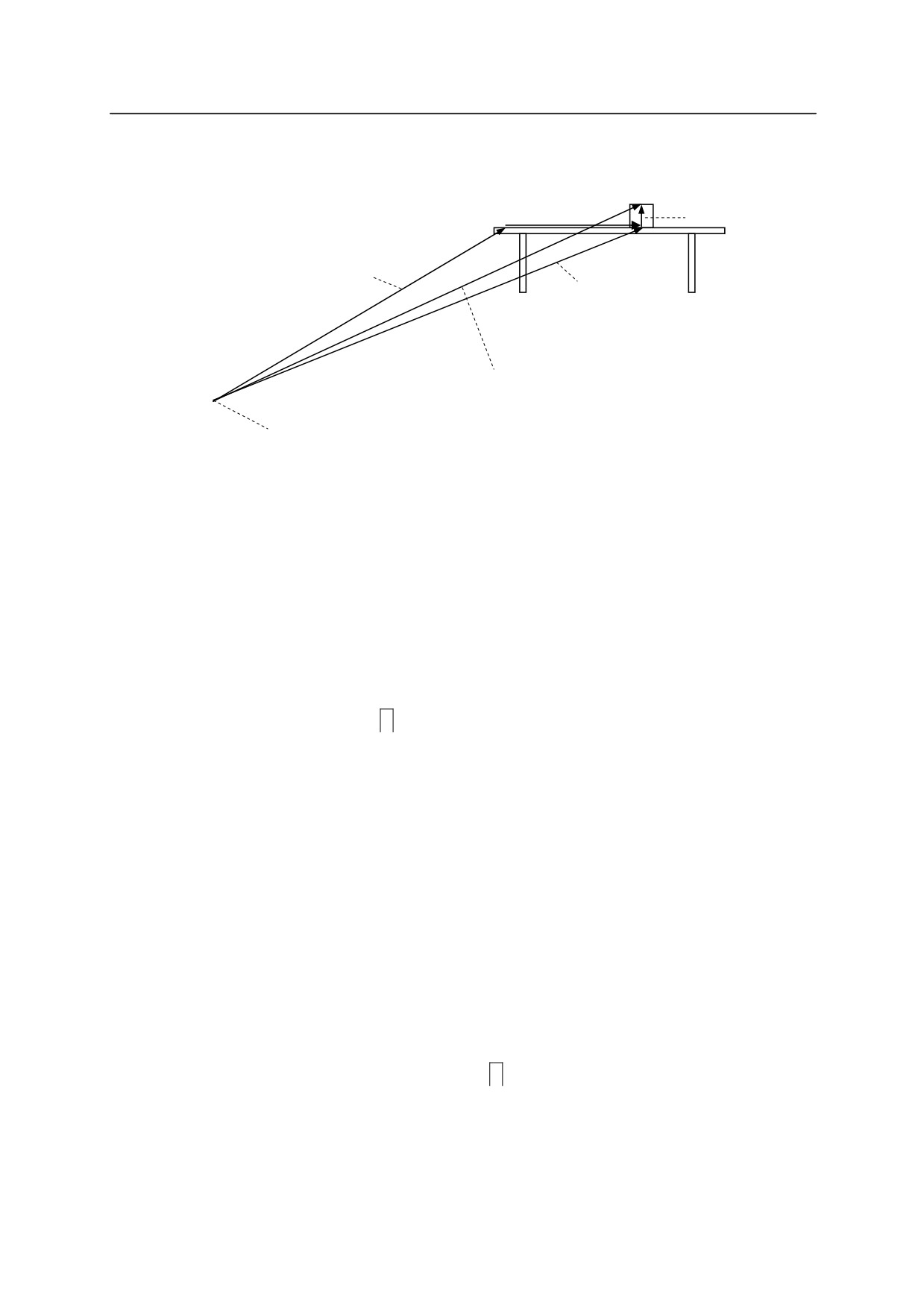
For example, say that “plate” is the name of the variable defined by the transformation values
relative to the base coordinates describing the coordinates at the table where the object is placed.
Then, if the pose of an object relative to the pose “plate” is defined as “object”, the compound
transformation values of the object relative to the robot base coordinates can be described as
“plate+object”.
In the example below, even if the pose “plate” changes (e.g. the table moves), only the
transformation values for “plate” will need revising and the rest can be used as is.
3-15
3. Information Expressions in AS Language
Pose to pick up
the object
object
pickup
Object pose
plate
plate+object
plate+object+pickup
Origin of robot base
coordinate
The compound transformation values can be defined㻌 in various ways. Normally, the
transformation values for a coordinate in reference with the robot base coordinate is defined.
Then the next transformation values for the coordinate in reference to that coordinate are defined,
and so on. The transformation values can be defined using any command or instruction used to
define pose variables.
(It is easiest to use the HERE command/ instruction.)
First, use the teach pendant to move the robot tool to the pose that is to be named “plate”. Then,
enter as below to define that pose as plate.
>HERE plate
Next, move the robot tool to the pose to be named “object” and enter:
>HERE plate + object
The transformation value “object” now defines the current pose relative to “plate”* (If “plate” is
not defined at this point, “object” will not be defined and an error will occur).
Note * What appears on the screen after entering the HERE command is the transformation
values of the pose for the rightmost variable (i.e. “object” in this case). It is not the
values for “plate + value”. To see the values for “plate +object”, use the WHERE
command when the robot is at that pose.
Finally, move the robot hand to the pose where it picks up the object and enter:
>HERE plate + object + pickup
This last command defines “pickup” relative to the transformation values “object”.
As shown above, compound transformation values are defined by a combination of several
3-16
3. Information Expressions in AS Language
transformation values separated by “+”. Do not include any spaces in between the “+” and the
transformation values. Using this method, you can combine as many transformation values as
needed.
If the robot is to pick up the object at the pose specified as “pickup” defined relative to “object”,
the program will be written as follows:
JMOVE plate+object+pickup
or
LMOVE plate+object+pickup
[ NOTE ]
1. Do not change the order in which the relative transformation is expressed. For
example, if the transformation value of pose variable “b” is defined relatively to
transformation value of pose variable “a”, “a+b” results as expected, but “b+a”
may not.
2. The pose data “object” and “pickup” from the example above are defined in
relation to other pose data. Therefore, do not use commands such as “JMOVE
object” or “LMOVE pickup” unless you are certain of its purpose and its effect
on the program.
When using compound transformation values repeatedly, use the POINT command to lessen the
time to calculate the compound transformation values. For example, to approach the pose
“pickup” and then to move to that pose, you might enter:
JAPPRO plate + object + pickup, 100
approach 100 mm above “pickup”
LMOVE plate + object + pickup
move in linear motion to “pickup”
Instead, if you enter as below, this will save calculation time:
POINT x = plate + object + pickup
calculate the target pose
JAPPRO x, 100
approach 100 mm above the target
LMOVE x
move in linear motion to the target
These two programs result in the same motion, but the latter calculates the compound
transformation only once, so the execution time is shorter. In such simple examples, the
difference will be minor, but in more complex programs, it may make a big difference and
improve overall cycle time.
3-17

3. Information Expressions in AS Language
[ NOTE ]
For robots with 7 joints, note the following:
1. When using POINT command, note the value of JT7. For example, in
POINT p=p1+p2
The value of JT7 assigned to “p” will be the value of JT7 for “p2”. The value of
the rightmost variable on the right side of the expression is assigned to the variable
p on the left side as JT7 value.
2. When assigning a specific value to JT7, add “/7” to the end of the POINT
command. For example,
POINT/7 p = TRANS(,,,,,,value)
assigns “value” to the variable “p” as JT7 value.
3-18
3. Information Expressions in AS Language
3.6 DEFINING REAL VARIABLES
Real variables are defined by using the assignment instruction (=). The format for assigning a
real variable is:
Real variable = numeric value
Example
a=10.5
count=i*2+8
Z[2]=Z[1]+5.2
The variable on the left side may be either a scalar variable (i.e., count) or an array element (i.e.,
Z[2]). A variable is defined only when a value is assigned to it. It remains undefined until a
value is assigned, and if a program using an undefined variable is executed, an error occurs.
The numeric value on the right side may be a constant, a variable or a numeric expression.
When the assignment instruction is processed, the value on the right side of the assignment
instruction is computed first, and then the value is assigned to the variable on the left side.
If the variable on the left side of the instruction is a new one and has never been assigned a value
before, the value on the right is assigned to that variable automatically. If the left side variable is
already defined, the new value will replace the current value.
For example, the instruction “x=3” assigns the value 3 to the variable “x”. It is read, “assign 3 to
x” and not “x is equal to 3”. The following example illustrates the processing order clearly:
x= x+1.
If this example is a math equation, it is read “x is equal to x plus 1”, which does not make sense.
As an assignment instruction, it is read, “assign the value of x plus 1 to x”. In this case, the sum
of the current value “x” and 1 is calculated and then the resulting value is assigned to “x” as a
new value. Such an equation requires that x be defined in advance, as below:
x=3
x=x+1
In this case, the resulting value of “x” is 4.
3-19
3. Information Expressions in AS Language
3.7 DEFINING CHARACTER STRING VARIABLES
Character string variables are defined by using the assignment instruction (=). The format for
assigning a character variable is:
$string variable=character string value
Example
$a1=$a2
$error mess[2]="time over"
The string variable on the left can be a variable (i.e., $name), or an array element (i.e., $line[2]).
A variable with specified name is defined only when a value is assigned to it. It remains
undefined until a value is assigned, and if a program using an undefined variable is executed, an
error occurs.
The character string on the right side may be a string constant, a string variable or a string
expression. When an assignment instruction is processed, the value on the right side is
computed first, and then the value is assigned to the variable on the left side.
$name = "KAWASKI HEAVY INDUSTRIES LTD."
In the above instruction, the string enclosed in “” will be assigned to the variable “$name”. If
the variable on the left side of the instruction has never been used before, this string will be
assigned automatically. If the left side variable is already defined, the new value specified on
the right side will replace the current value.
3-20

3. Information Expressions in AS Language
3.8 NUMERIC EXPRESSIONS
Numeric expressions may consist of numerals, variables, specific functions or other numeric
expressions combined together with operators. All numeric expressions evaluated by the system
result in real number values. Numeric expressions can be used anywhere in place of numeric
values. They can be used as parameters in monitor commands and program instructions, or as
array indexes.
The interpretation of the value depends on the context in which the expression appears. For
example, an expression specified for an array index is interpreted as yielding an integer value.
An expression specified for a logical value is interpreted as false when it is evaluated as 0, and
true if it is other than 0.
3.8.1 OPERATORS
For describing expressions, arithmetic, logical, and binary operators are provided. All the
operators combine two values to obtain a single resulting value. Exceptions: the two operators
(NOT and COM) operate on a single value and the operator () operates on one or two values.
The operators are described below.
Arithmetic
+
Addition
Operators
Subtraction or negation
Multiplication
/
Division
^
Power
MOD
Remainder
Relational
<
Less than
Operators
<=, =<
Less than or equal to
==
Equal
<>
Not equal to
>=, =>
Greater than or equal to
>
Greater than
Logical
AND
Logical AND
Operators
NOT
Logical complement
OR
Logical OR
XOR
Exclusive logical OR
Binary
BAND
Binary AND
Operators
BOR
Binary OR
BXOR
Binary XOR
COM
Complement
3-21
3. Information Expressions in AS Language
[ NOTE ]
1. Relational operator “==”is a operator to check if the two values are equal, and different
from the assignment indicator “=“.
2. Binary operator BOR performs OR operation for the respective binary bit of two
numeric values.
(In this example the value is expressed in binary notation, but this
operation may be used with any notation.)
^B101000 BOR
^B100001
^B101001
This result is different from what you can get in OR operation.
^B101000 OR
^B100001
-1(TRUE)
In this case, ^B101000 and ^B100001 are interpreted as logical values, and since
neither is 0 (FALSE), the expression is evaluated as TRUE.
3.8.2 ORDER OF OPERATIONS
Expressions are evaluated according to a sequence of priorities. The priority is listed below,
from 1 to 14. Note that the order of operations can be controlled using parentheses to group the
components of an expression. With expressions containing parentheses, the expression within
the innermost pair of parentheses is evaluated first, and then the system works toward the outer
most pair.
1. Evaluate functions and arrays
2. Process relational operators concerning character strings (See 3.9 String Expressions)
3. Process power operator “^”
4. Process unary operators “-“(negation), NOT, COM
5. Process multiplication “*” and division”/” from left to right
6. Calculate remainder (MOD operation) from left to right
7. Process addition”+” and subtraction”-“ from left to right
8. Process relational operators from left to right
9. Process BAND operators from left to right
10. Process BOR operators from left to right
11. Process BXOR operators from left to right
12. Process AND operators from left to right
13. Process OR operators from left to right
14. Process XOR operators from left to right
3-22
3. Information Expressions in AS Language
3.8.3 LOGICAL EXPRESSIONS
Logical expressions result in logical value TRUE or FALSE. A logical expression can be used
in a program as a condition to determine the next operation in a program. In the following
example, a simple logical expression, “x>y”, is used in a subroutine to determine which of the
two variables to assign to variable “max”.
IF x>y GOTO 10
max=y
GOTO 20
10
max=x
20 RETURN
When evaluating logical expressions, the value zero is considered FALSE and all nonzero values
are considered TRUE. Therefore, all real values or real value expressions can be used as a
logical value.
For example, the following two statements have the same meanings.
IF x GOTO
10
IF x<>0 GOTO 10
However, the second statement shows the logical operator clearly and is easier to understand. It
is recommended to use the logical operators.
3-23

3. Information Expressions in AS Language
3.9 STRING EXPRESSIONS
String expressions consist of character strings, string variables, specific functions or other string
expressions combined together with operators. The following operators are used with the string
expressions.
String operator
+
Combine
<
Less than
<=, =<
Less than or equal to
Relational
==
Equal to
operators
<>
Not equal to
>=, =>
Greater than or equal to
>
Greater than
The result of using the string operator will be a string, and that of using relational operators will
be a real value.
When using relational operators with character strings, the strings are compared character for
character from the first character in the string. If all the characters are the same, the two strings
are considered equal, but if there is even one difference, the string with the character having
higher character code is evaluated as the greater string. If one of the strings is shorter, the
shorter one is evaluated less. In relational operations with strings, spaces and tabs are regarded
as a character.
"AA"
< "AB"
"BASIC" == "BASIC"
"PEN."
> "PEN"
"DESK"
< "DESKS"
[ NOTE ]
Uppercase and lowercase letters in string expressions are regarded as different characters.
3-24
4. AS Program
4.0 AS PROGRAM
This chapter explains about AS programs. It explains about programming and execution of
programs, and about the robot motions. For better understanding, actually operate the actual
system or PC-ROSET* as you read this chapter.
Note* PC-ROSET is a personal computer robot simulator compatible with the AS system.
4.1 TYPES OF AS PROGRAMS
A program is a series of instructions telling the robot how to move, output signals, do calculations
etc. per a set process. A program name consists of no more than 15 characters starting with an
alphabetical character, and can contain only letters, numbers, and periods. You can create as
many programs as the memory can store. Programs are usually created using the AS system
editor mode, but you may also use a separate computer loaded with KRterm or
KCwin32/KCwinTCP terminal software or PC-ROSET and later load it to the robot memory.
4.1.1 ROBOT CONTROL PROGRAM
Robot control programs are programs that control the robot movements. You may use all the
program instructions including robot motion instructions to create these programs.
4.1.2 PC PROGRAM (PROCESS CONTROL PROGRAM)
PC or process control programs are programs executed simultaneously with the robot control
programs. PC programs are commonly used to control or monitor external devices by
monitoring external I/O signals. The PC program and the robot control program can
communicate with each other by using common variables or internal signals.
PC programs and robot control programs use instructions in common. Therefore, in some cases,
a PC program can be executed as a robot control program. However, motion instructions other
than BRAKE instruction cannot be used in PC programs. BASE and TOOL functions are also
not available for PC programs.
4-1
4. AS Program
[ NOTE ]
The execution time of each step in the program differs according to the instruction
included in the program, and the number of programs running simultaneously. If the
execution time needs to be shortened, take countermeasures such as to halt the execution
of other programs using wait instructions such as TWAIT, or reduce the number of
programs running at the same time, etc.
4.1.3 AUTOSTART
A PC program can be set to start automatically when the controller power is turned ON.
1. Turn ON the system switch AUTOSTART.PC (or AUTOSTART2.PC -
AUTOSTART5.PC).
2. Create the program you want to start automatically and name it AUTOSTART.PC (or
AUTOSTART2.PC - AUTOSTART5.PC).
Some monitor commands can be executed in programs by using program instruction MC;
e.g. MC CONTINUE, etc.
(See 6.9 MC program instruction.)
This is a sample autostart program. In this example, after the controller power is turned ON, the
robot monitors for motor power ON and executes program pg1 when it is turned ON. For easier
understanding safety checks are ignored here, but in actual usage, be sure to include safety check
procedures.
autostart.pc( )
1 WAIT SWITCH (POWER)
;waits for motor power ON
2 WAIT SIG(27)
;checks if the robot is at home pose*
3 MC EXECUTE pg1
;Executes pg1(robot motion program)
Note * Set home pose and assign the dedicated signal HOME1 to signal 27, before㻌 executing
this program.
4-2
4. AS Program
4.2 CREATING AND EDITING PROGRAMS
In this section, a simple program is made to instruct the robot to perform a task. A program is a
list of procedures that the robot will be made to do. When executing a program through the AS
system, program steps (lines) are processed in order from top to bottom and the operations
defined in each step are carried out by the robot.
4.2.1 AS PROGRAM FORMAT
Each line (step) of an AS language program is expressed in the following format.
step number label program instruction
;comment
1. Step number
A step number is automatically assigned to each line of a program. Steps are numbered
consecutively beginning with 1 and are automatically renumbered whenever lines are inserted
or deleted.
2. Label
Labels are used in a program to branch the program. A label can be either an integer from 1
to 9999 or a string of up to 15 alphanumeric characters, periods or underscores (starting with
alphabetical character), followed by a colon (:). Labels are inserted at the beginning of a
program line, right after the step number. Labels can be used as branch destinations from
anywhere within the program.
3. Comment
A semicolon (;) indicates that all information to the right of the semicolon is a comment.
Comments are not processed as program instructions when the program is executed, and are
only used for explaining the program contents. You can make a program line with only a
comment and no label or instruction. Blank lines can also be made to improve program
legibility.
(A blank line consists of at least one space or tab after the semicolon.)
4-3

4. AS Program
4.2.2 EDITOR COMMANDS
The following editor commands are used to create and edit programs.
(Highlighted parameters
can be omitted.)
EDIT program name, step
Starts editor mode.
Program instructions
Replaces the current steps with a new instruction.
ENTER key (
)
Goes to the next step without changing the current step.
D number of steps
Deletes specified number of program steps. (Delete)
E
Exits editor mode, and returns to monitor mode.(Exit)
F character string
Searches characters and displays that line.
(Find)
I
Inserts a new step.
L
Displays the previous step. (Last)
M /existing characters
Replaces the existing characters with new characters.
/new _characters
(Modify)
O
Places the cursor on current step for editing. (One line)
P number of steps
Displays specified number of program steps. (Print)
R character string
Replaces characters within a step.
S step number
Selects program step. (Step)
XD
Cuts the selected step or steps and stores in clipboard.
XY
Copies the selected step or steps and stores in clipboard.
XP
Pastes the content of clipboard.
XQ
Pastes the content of the clipboard in the reverse order.
XS
Shows the contents of the clipboard.
T
Teaches while in editor mode (option).
4-4
4. AS Program
4.2.3 PROGRAMMING PROCEDURES
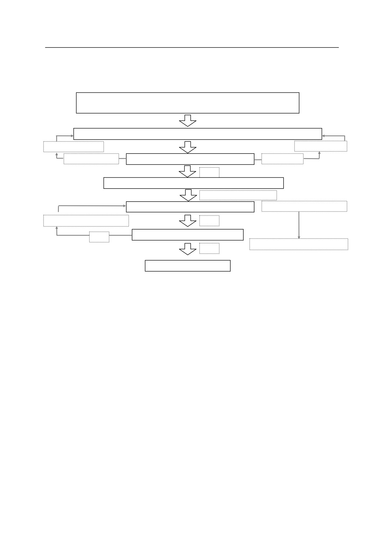
Programming is done as shown in the following steps:
Preparing for programming: Plan/confirm the robot operation steps,
confirm mode and switches, start Edit
d
Create program (EDIT command) / Teach pose (TEACH/HERE command)
Modify program
Teach pose
Program N.G.
Is the program/pose correct?
Pose N.G.
OK
Repeat cycle: confirm the mode/switches, specify speed
EXECUTE command
Is the program /pose correct?
Program/pose N.G.
Gradually increase speed
OK
Is it at the specified speed?
NO
Modify program/pose data
OK
Regular repeat cycles
4.2.4 CREATING PROGRAMS
In an AS program, two things have to be taught to the robot:
1. Working conditions for the robot
2. Path (pose) to be followed by the robot tool
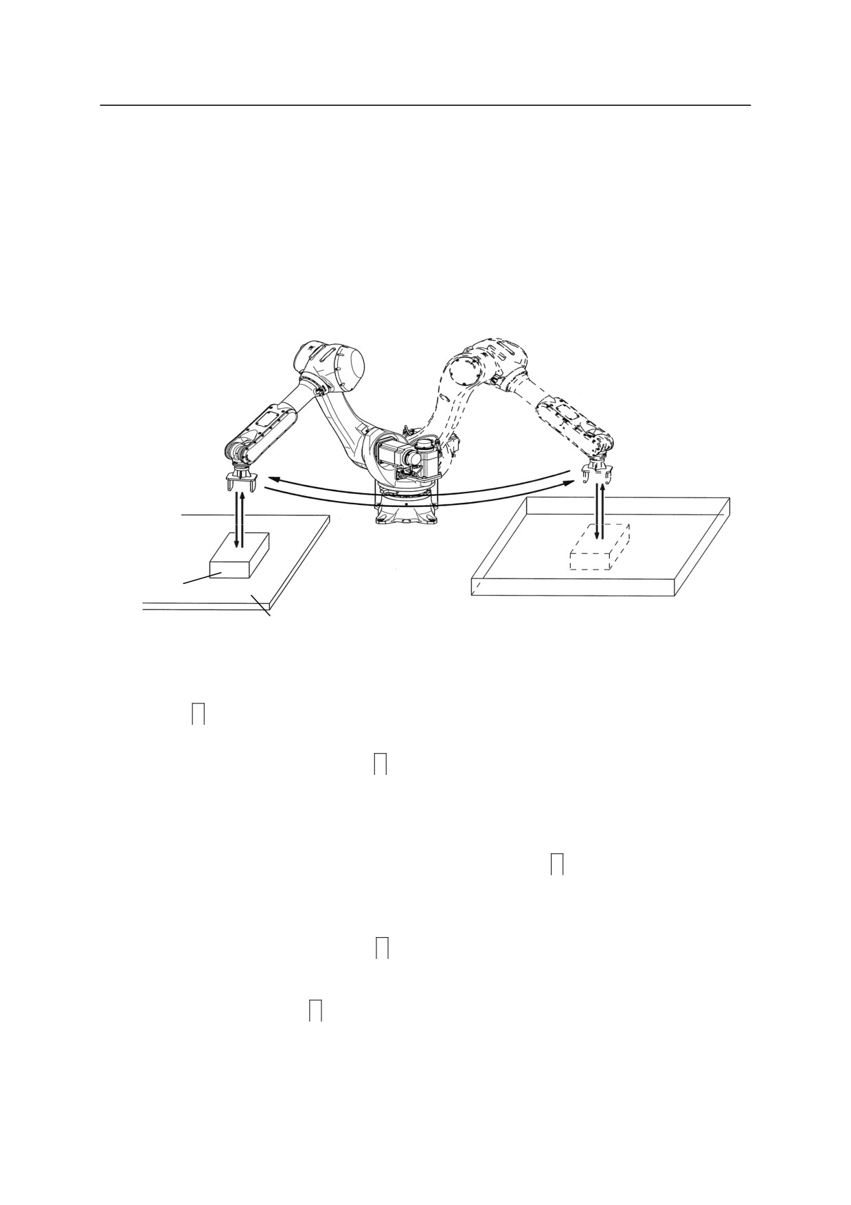
Here is a sample program. The robot will perform the task shown on the next page: pick up
a part fed in by the supply shoot (conveyor), and place it in the box.
First define all the motions required to complete the task:
1. Check if the hand is open.
2. Move to a pose 50 mm above the part (#part) on the supply shoot.
3. Move straight down to the part (#part).
4. Close the hand and grab the part.
5. Move straight up 150 mm above the supply shoot.
6. Move to a position 200 mm above the box (#box).
4-5
4. AS Program
7. Move the part down into the box.
8. Open the hand and release the part.
9. Move back up to a position 180 mm above the box.
The variables #part and #box which express the position and the orientation of the robot are
called pose data in the AS system. Define the pose variables as shown in Chapter 3 before
executing the program.
2.(1.)
3.
5.
9.
6.
7.
(4.)
(8.)
part
#box
#part
Programs are created and edited via AS Editor. To create a program named “demo”, enter
“EDIT demo
”. The screen should appear as follows:
> EDIT demo
.PROGRAM demo
1 ?
Now, AS is waiting for the first step to be entered. Enter “OPENI
” after “1?”
> EDIT demo
.PROGRAM demo
1 ? OPENI
2 ?
Next enter “JAPPRO #part, 50
”for the second step.
> EDIT demo
4-6