Kawasaki Robot Controller E Series. Reference Manual (2015) - page 13

7. System Switches
TOUCHST.ENA
㻌 㻌 㻌 㻌 㻌 㻌 㻌 㻌 㻌 㻌 㻌 㻌 㻌 㻌 㻌 㻌 㻌 㻌 㻌 㻌 㻌 㻌 㻌 㻌 㻌 㻌 㻌 㻌 㻌 㻌 㻌 㻌 㻌 㻌 㻌 㻌 㻌 㻌 㻌 㻌 㻌 㻌 㻌 㻌 㻌 㻌 㻌 㻌 㻌 㻌 㻌 㻌 㻌 㻌 㻌 㻌 㻌 㻌 㻌 㻌 㻌
Function㻌
Selects whether touch panel operation of status lamps (HOLD/RUN, Motor power, Cycle
start) are enabled or disabled. When set to disable, avoids mistaken operation of the touch
panel when the touch panel is touched accidently.
㻌
Explanation㻌
When this switch is ON, status lamp can be operated from touch panel.
When this switch is OFF, status lamp cannot be operated from touch panel.
㻌㻌
Default setting is ON.
㻌
TPSPEED.RESET
㻌
Function㻌
Selects whether teach speed and check speed is set to slow speed automatically or not.
The timing slow speed is set is as follows:
(1) When switched from repeat mode to teach mode
(2) When Controller power is turned ON
(3) When emergency stop switch is pressed
Sow speed is not set when in inching operation.
㻌
Explanation㻌
When this switch is ON, teach and check speeds are automatically changed to slow speed.
When this switch is OFF, teach and check speeds are not automatically changed to slow
speed.
Default setting is ON.
㻌
㻌
7-29
7. System Switches
OXZERO
Option
Function㻌
Selects whether external output signal (OX) collective reset function is enabled or disabled.
When the function is enabled, “OX=0” can be taught and the OX signals of the taught step are
reset together.
However, dedicated signals and interface panel signals cannot be reset.
This function is valid only when multi-function OXWX function option is valid.
Explanation㻌
When this switch is ON, collective reset function is enabled.
When this switch is OFF, collective reset function is disabled.
㻌
Default setting is OFF.
IFAKEY
Function㻌
Selects whether the press buttons on the interface screen and press buttons with lamp are
enabled only with A key or not. Buttons in operation disable status and those set to
operation disables cannot be operated.
㻌
Explanation㻌
When this switch is ON, allows operation only when pressed together with A key.
When this switch is OFF, allows operation without pressing A key.
㻌
Default setting is OFF.
7-30

7. System Switches
DISP.EXESTEP
㻌
Function㻌
Displays the current stepper of the execution step during program execution instead of current
motion step.
㻌
Explanation㻌
For example, if the program is executed in condition as below, when this switch is ON, the
stepper step of SWAIT is displayed. (SWAIT can be skipped.) When this switch is OFF,
motion instruction A is displayed.
Motion Step A
(Start)
×
×
Non-motion instruction sub-routine
×
SWAIT←Stepper
×
×
Default setting is ON.
NO_SJISCONV
㻌
Function㻌
Selects whether the function to convert the character code between SJIS and EUC at time
save/ load is enabled or disabled.
㻌
Explanation㻌
When this switch is ON, character code conversion is conducted.
When this switch is OFF, character code conversion is not conducted.
㻌
Default setting is ON.
7-31
7. System Switches
CONF_VARIABLE
Function㻌
Selects whether the configuration change is allowed at time of linear motion or not.
Normally, the configuration is kept the same during the linear motion, but when the robot
passes a singular point, some axes change greatly in the command value and robot may not be
able to move. Configuration can be changed to avoid this and pass the singular point.
㻌
Explanation㻌
When this switch is ON, allows configuration during linear motion.
When this switch is OFF, does not allow configuration during linear motion.
㻌
Default setting is ON.
INVALID.TPKEY_S
㻌
Function㻌
Selects whether or not the shift status is invalidated when A key is pressed.
㻌
Explanation㻌
When this switch is ON, pressing A key only turns ON 䇾TPKEY_A䇿 and 䇾TPKEY_S䇿
remains OFF.
When this switch is OFF, pressing A key turns ON both 䇾TPKEY_A䇿 and 䇾TPKEY_S䇿.
㻌
Default setting is OFF.
7-32
7. System Switches
DIVIDE.TPKEY_S
㻌
Function㻌
Selects whether the information of the two A keys on the teach pendant are allocated to
switches 䇾TPKEY_A䇿 and 䇾TPKEY_S䇿 or not.
㻌
Explanation㻌
When this switch is ON, the information of the two A keys are allocated to the switches as
shown below:
Left A key: TPKEY_S
Right A key: TPKEY_A
When INVALID.TPKEY_S switch is ON, TPKEY_S switch is invalidated.
㻌
When INVALID.TPKEY_S switch is the information from the two A keys are united to one
and allocated to both TPKEY_A and TPKEY_S switches.
㻌
Default setting is OFF.
SIGRSTCONF
㻌
Function㻌
Changes the number of signals that are reset when signal 0 is output via SIGNAL instruction
or manual signal output.
Explanation㻌
When this switch is ON, outputting signal 0 resets 1 to the number of external output signals
set by ZSIGSPEC instruction (maximum of 960) .
When this switch is OFF, outputting signal 0 resets 1 to 64 signals (1 to 256 when OX/WX
signal expansion function is ON).
㻌
Default setting is ON.
7-33

7. System Switches
SINGULAR
㻌
Function㻌
Switches between singular point check function enable and disable.
㻌
Explanation㻌
When this switch is ON, checks whether the taught point or the command values for JT 5 are
within range of 0º to the threshold values (for example 5º) when moving in linear or circular
motion. If the value is within the range, error (E6007) “Wrist can't be straightened any more
(Singular point 1).” occurs.
㻌
Default setting is ON (in some model the default setting is OFF).㻌
㻌
㻌
㻌
㻌
㻌
㻌
㻌
㻌
㻌
㻌
USE_ISO8859_5
㻌
Function㻌
Changes the display font of ASCII8 bit from Latin font to Cyrillic font.
㻌
Explanation㻌
When this switch is OFF, ASCII8 bit (0xA1 - 0xFF) is displayed in Latin font (ISO8859-1).
When this switch is ON, the font is displayed in Cyrillic font (ISO8859-5).
㻌
Default setting is ON.
7-34

8. Operators
8.0 OPERATORS
This chapter describes how the operators function in AS language. These operators are used in
conjunction with monitor commands and program instructions.
8.1 ARITHMETIC OPERATORS
Arithmetic operators are used to perform general mathematic calculations.
Operator
Function
Example
+
Addition
i = i + 1
Subtraction
j= i 1
Multiplication
i = i 3
/
Division
i = i/2
MOD
Remainder
i= i MOD 2
^
Power
i = i ^ 3
Example
i = i + 1
The value of i plus 1 is assigned to i; e.g. when i is 5, 6 will be assigned to i
as the result of the expression i + 1.
i = i MOD 2
When i is 5, operator calculates 5 2 and assigns to i the remainder of 1.
i = i^3
The value of i3 is assigned to i. When i is 2, 8 is assigned to i on the left
side of the instruction.
In division (/) and MOD, using 0 as the rightmost value of the instruction results in an error.
Example
i = i/0
i = i MOD 0
8-1

8. Operators
8.2 RELATIONAL OPERATORS
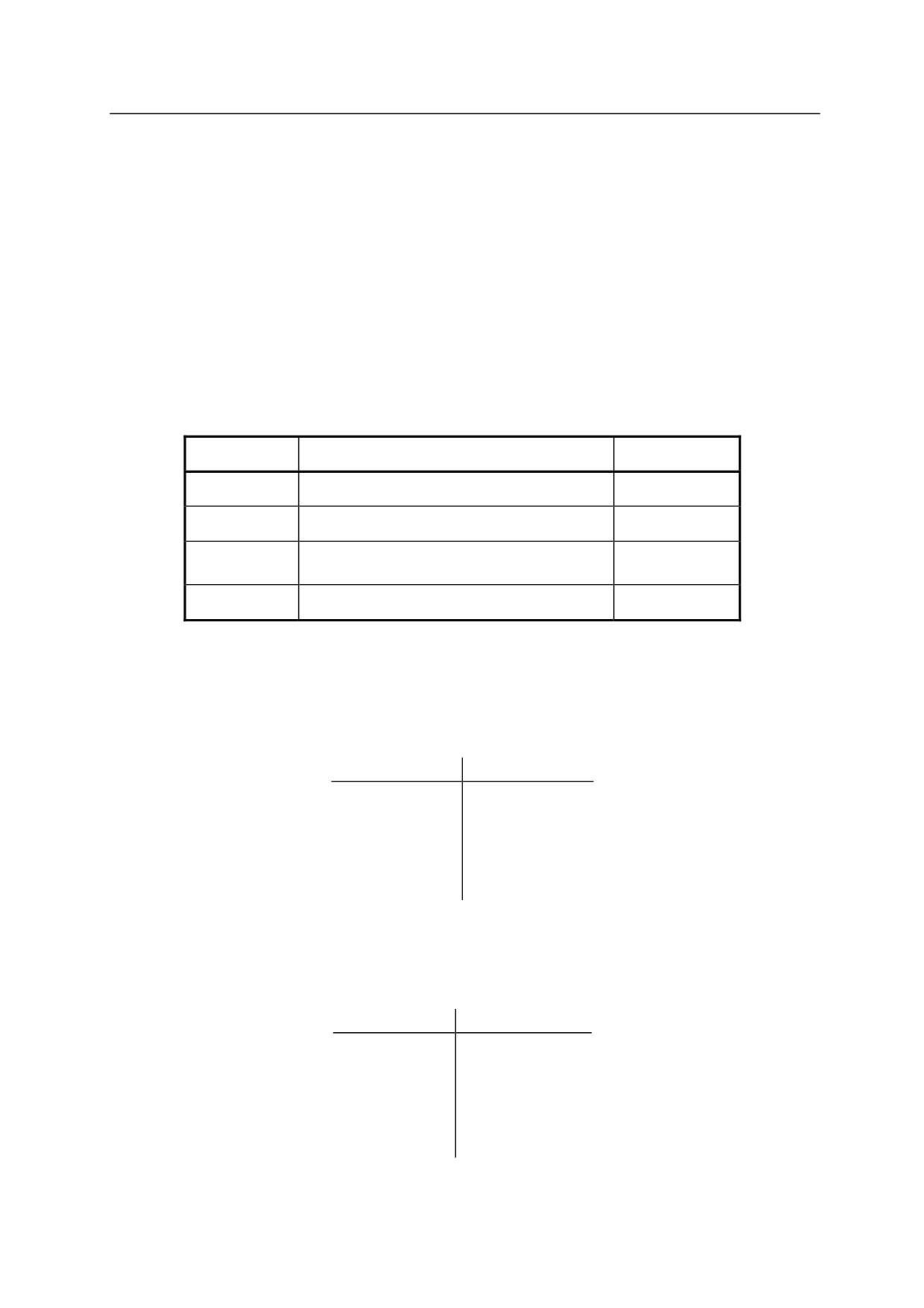
Relational operators are used with instructions such as IF and WAIT to verify if a condition is set.
Operator
Function
Example
<
TRUE (1) when left side value is less than right side
i < j
>
TRUE (1) when left side value is greater than right side
i > j
<=
TRUE (1) when left side value is less than or equal to right side
i<= j
=<
Same as above
i =< j
TRUE (1) when left side value is greater than or equal to right
>=
i >= j
side
=>
Same as above
i=> j
==
TRUE (1) when the two sides are equal
i == j
<>
TRUE (1) when the two sides are not equal
i <> j
Example
IF i <j GOTO
10
When j is greater than i, (i.e. the instruction i<j is true), the
program jumps to the step labeled 10. If not, the program
proceeds to the next step.
WAIT INT(t)==INT(5)
When t is 5 (i.e. t==5 is true), the program proceeds to the next
step, if not, program execution is suspended until the condition is
set.
IF i+j>100 GOTO
20
When i + j is greater than 100 (i.e. the expression i + j > 100 is
true), the program jumps to the step labeled 20. If not, the
program proceeds to the next step.
IF
$a =="abc" GOTO 20
When $a is “abc” (i.e. $a == “abc” is true), the program jumps to
the step labeled 20. If not, the program proceeds to the next step.
[ NOTE ]
When comparing real values, do not use “==”. In the AS software, real values are
treated as decimal floating point. In decimal floating points, real values cannot be
checked is they are equal using “==”. To compare real values and integer values,
use INT or ROUND functions.
8-2
8. Operators
8.3 LOGICAL OPERATORS
Logical operators are used in Boolean operations such as 0 + 1 = 1, 1 + 1 = 1, 0 + 0 = 0 (logical
OR), or 0 × 1 = 0, 1 × 1 = 1, 0 × 0 = 0 (logical AND). There are two types of logical operators
in AS language, logical operators and binary operators.
Logical operators are not used for calculating numeric values, but for determining if a value or an
expression is true or false. If a numeric value is 0, it is considered FALSE (OFF). All nonzero
values are considered TRUE (ON). Take note that the calculation using this operator returns 1
as TRUE.
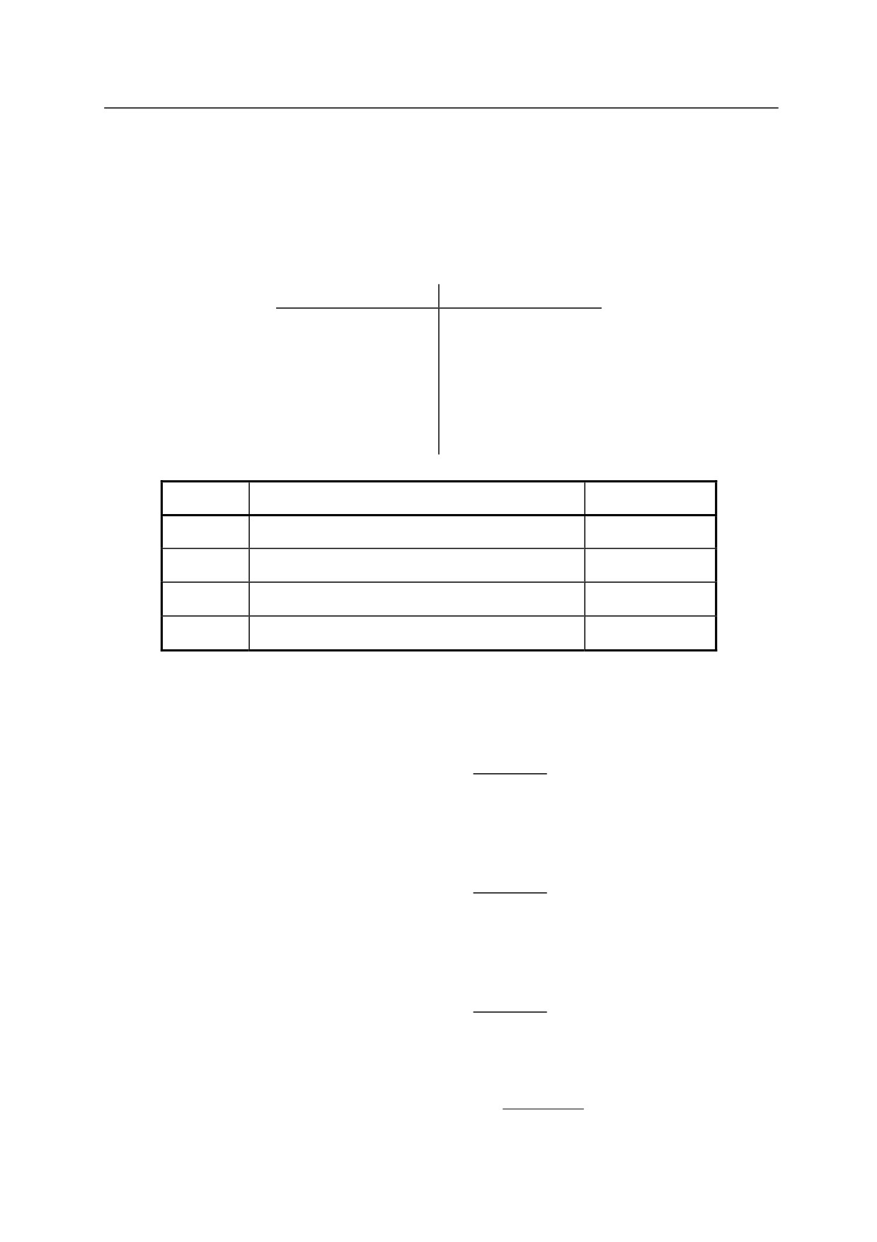
Operator
Function
Example
AND
Logical AND
i AND j
OR
Logical OR
i OR j
XOR
Exclusive logical OR
i XOR j
NOT
Logical complement
NOT i
Example
i AND j
Evaluates the logical AND between i and j. The variables i and j are generally
logical values, but they can also be real number values. In this case, all real
number values other than 0 are considered ON (TRUE).
i
j
Result
0
0
0 (OFF)
0
not 0
0 (OFF)
not 0
0
0 (OFF)
not 0
not 0
1 (ON)
The result is ON (TRUE) only when both values are ON (TRUE).
i OR j
Evaluates the logical OR between i and j.
i
j
Result
0
0
0 (OFF)
0
not 0
1 (ON)
not 0
0
1 (ON)
not 0
not 0
1 (ON)
The result is ON (TRUE) when both or either of the two values are ON (TRUE).
8-3
8. Operators
i
XOR j
Evaluates the exclusive logical OR between i and j.
i
j
Result
0
0
0 (OFF)
0
not 0
1 (ON)
not 0
0
1 (ON)
not 0
not 0
0 (OFF)
The result is ON (TRUE) when only one of the two values is ON (TRUE).
NOT i
Evaluates the logical complement of i.
i
Result
0
1 (ON)
not 0
0 (OFF)
In AS, the logical status of a value or expression may be expressed as following:
True: not 0, ON, TRUE
False:
0, OFF, FALSE
8-4
8. Operators
8.4 BINARY OPERATORS
Binary logical operators perform logical operations for each respective bit of two numeric values.
For example, if a number is composed of 4 bits, the values that will be calculated will be 0000,
0001, 0010, 0011, ……, 1111 (In AS, the numeric values are composed of 32 bits).
Binary expression
Decimal expression
0000
0
0001
1
0010
2
0011
3
:
:
:
:
1111
15
Operator
Function
Example
BOR
Binary OR
i BOR j
BAND
Binary AND
i BAND j
BXOR
Binary XOR
i BXOR j
COM
Binary complement
COM i
Example
i BOR j
If i=5, j=9, then the result is 13.
i=5
0101
j=9
1001
1101 13
i BAND j
If i=5, j=9, then the result is 1.
i=5
0101
j=9
1001
0001
1
i BXOR j
If i=5, j=9, then the result is 12.
i=5
0101
j=9
1001
1100 12
COM i
If i=5 then the result is 6.
i=5 0…
0101
1…
1010 6
8-5
8. Operators
8.5 TRANSFORMATION VALUE OPERATORS
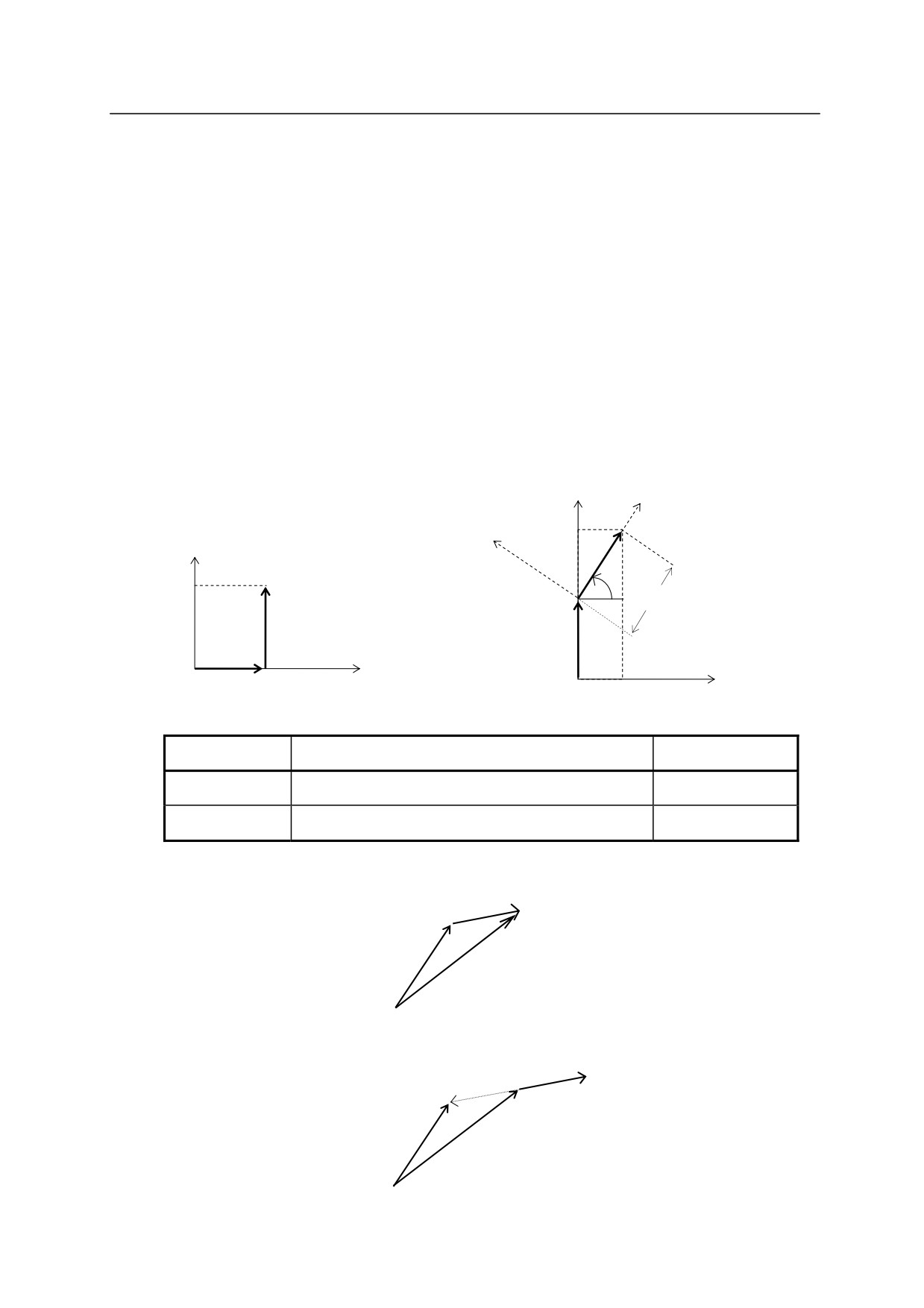
In the AS system, operators + and are used to determine the compound transformation values
(the XYZOAT values). However note that unlike the usual addition or subtraction, the
commutative law does not hold true with the transformation operation. Arithmetic expression
“a + b” and “b + a” will result the same, but “pose a + pose b” will not necessarily equal “pose b
+ pose a”. This is because in transformation operations, the values of the axes are taken into
consideration. An example of this is shown below:
a1 = (1000,
0,
0,
0,
0,
0)
a2 = (
0, 1000,
0,
60,
0,
0)
a1 + a2 = (1000, 1000,
0, 60,
0,
0)
a2 + a1 = (500, 1866,
0, 60,
0,
0)
x
Y
y
1866
Y
a1
60
1000
1000
1000
a2
a2
X
a1
1000
X
500
Operator
Function
Example
+
Addition of two transformation values
pos.a + pos.b
Subtraction of two transformation values
pos.a pos.b
Example
pos.b
pos.a + pos.b
pos.a
pos.a + pos.b
pos.a pos.b
pos.b
pos.b
pos.a pos.b
pos.a
8-6

8. Operators
Transformation operator “” used with a single value (e.g. x) signifies the inverse value of x.
For example, when the transformation value variable pos.b defines the pose of object B relative
to object A, then pos.b defines the pose of object A relative to object B.
pos.b
pos.b
In the example below, “hole1” is to be defined relative to “part1” (defined in advance). This
can be done using the compound transformation value variable part1+hole.
Move the robot to the pose to be defined “hole1” and teach that pose as “hole” using the HERE
command. Using this pose (“hole”), “hole1” can be defined.
POINT hole1 = (part1) + hole
part1 + hole = hole1
part1
hole
Another way to define “hole1” without using the operator “” is by writing “hole1” in the left
side of the expression in POINT command. The following command also defines “hole1”.
POINT part1 + hole1 = hole
hole1
part1
part1 + hole1=hole
8-7

8. Operators
8.6 STRING OPERATORS
Operator
Function
Example
+
Combines two strings
$a = $b + $c
Example
$a=$b + $c
Combines $b + $c and assigns that string to $a.
When
$b=“abc”, $c=“123” then $a is “abc123”.
8-8
9. Functions
9.0㻌FUNCTIONS㻌
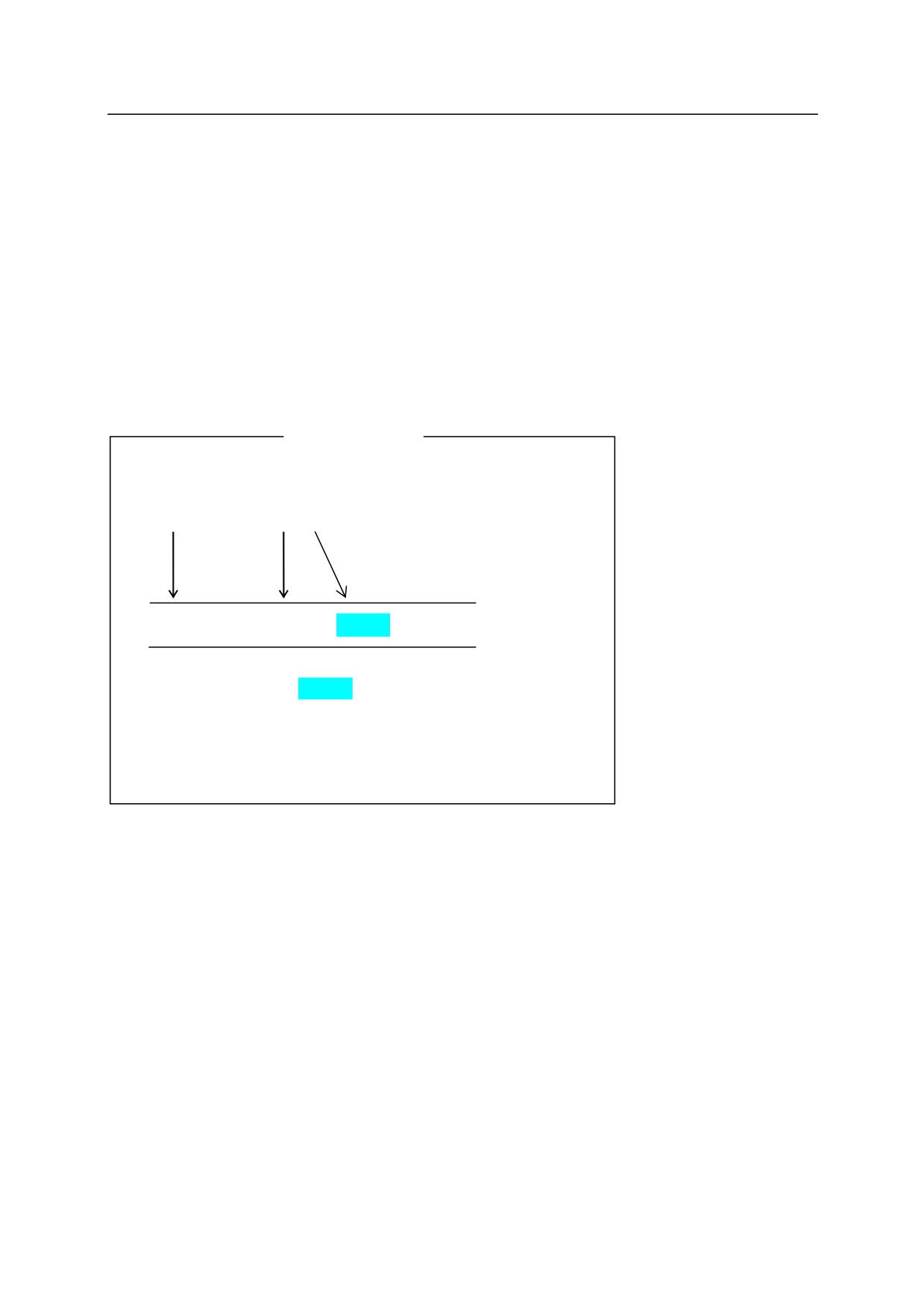
This chapter describes the functions used in AS system. Functions are generally used in
combination with monitor commands and program instructions. They are expressed in format
described below. The keyword specifies the function, and the parameters entered in parentheses
determine the value.
EXAMPLE
Keyword
Parameter
SIG
(signal number,㻌 ……)
Parameters marked by
can be omitted.
Always enter a space (blank) after the keyword.
9-1
9. Functions
9.1 REAL VALUE FUNCTIONS
SIG
Returns the logical AND of the specified signal.
BITS
Returns the value corresponding to the bit pattern of the signal 㻌
(Up to 16 signals).
BITS32
Returns the value corresponding to the bit pattern of the signal
(Up to 32 signals).
TIMER
Returns the current value of the timer.
DISTANCE
Returns the distance between two points.
DX, DY, DZ
Returns the displacement value of transformation values. (X, Y, Z)
DEXT
Returns the specified component of a pose.
ASC
Returns ASCII character values.
LEN
Returns string length.
TRUE, ON
Returns the value -1.0, which represents TRUE.
FALSE, OFF
Returns the value 0.0, which represents FALSE.
VAL
Returns the real value in the given string.
INSTR
Returns the value for the starting point of the specified string.
MAXVAL
Compares given values.
MINVAL
Compares given values.
INT
Returns the integer of a value.
MAXINDEX
Returns the value of the largest element in specified dimension.
MININDEX
Returns the value of the smallest element in specified dimension.
SWITCH
Returns the status of system switch.
WHICHTASK
Returns the task number selected by the program or subroutine.
TASK
Returns the status of program execution.
ERROR
Returns the error number.
PRIORITY
Returns the priority of robot program.
UTIMER
Returns the current timer value.
MSPEED
Returns monitor speed of Robot 1.
MSPEED2
Returns monitor speed of Robot 2.
INRANGE
Checks if pose is in motion range.
9-2
9. Functions
SYSDATA
Returns AS parameters.
EXISTJOINT
Returns if the specified joint displacement value variable exists or
not.
EXISTTRANS
Returns if the specified pose transformation value variable exists
or not.
EXISTREAL
Returns if the specified real value variable exists or not.
EXISTCHAR
Returns if the specified character string variable exists or not.
EXISTINTEGER
Returns if the specified integer variable exists or not.
EXISTPGM
Returns if the specified program exists or not.
Returns if the specified local joint displacement value variable
EXISTLOCALJOINT
exists or not.
Returns if the specified local pose transformation value variable
EXISTLOCALTRANS
exists or not.
Returns if the specified local real value variable exists or not.
EXISTLOCALREAL
Returns if the specified local character string variable exists or not.
EXISTLOCALCHAR
Returns if the specified local integer variable exists or not.
EXISTLOCALINTEGER
STRTOPOS
Returns the pose data for the specified string variable.
STRTOVAL
Returns the real value for the specified string variable.
ROUND
Returns the real value rounded at the first decimal place.
IQARM
Acquires the current value of the specified axis.
TRQNM
Acquires the torque value of the specified axis.
CURLIMM
Acquires the negative limit of external axis current limit
CURLIMP
Acquires the positive limit of external axis current limit
ENVCHKRATE
Acquires the set value for magnification ratio to the initial value of
deviation error detection
GETENCTEMP
Specifies the encoder temperature [°C] of the specified axis.
9-3

9. Functions
SIG (signal number䠈䈈䈈)㻌
㻌
Function㻌
Returns the logical AND of the specified binary signal status.
Parameter
Signal Number
Specifies the number of the external or internal I/O signal.
Explanation㻌
Calculates logical AND of all the specified binary signal states and returns the resulting value.
If all the specified signal states are TRUE, 1 (the value of TRUE) is returned. Otherwise 0 (the
value of FALSE) is returned. External I/O signals or internal I/O signals as shown below, are
specified by their numbers.
Acceptable Signal Numbers
External output signal
1 㻌 actual number of signals
External input signal
1001 actual number of signals
Internal signal
20012960
Signals specified by positive numbers are considered TRUE when they are ON, while signals
specified by negative number are considered TRUE when they are OFF. No signal corresponds
with signal number “0”, so it is considered always TRUE.
[ NOTE ]
There is a timing restriction when evaluating more than one signal at the same
time. When more than one signal is input at the same time, note that there is
approx. 2 ms difference in stabilization time of each signal.
Example㻌
If the binary I/O signals 1001=ON, 1004=OFF, 20=OFF, then
Results
SIG(1001)
1
TRUE
SIG(1004)
0
FALSE
SIG(1004)
1
TRUE
SIG(1001,1004)
0
FALSE
SIG(1001,1004)
1
TRUE
SIG(1001,1004,20)
1
TRUE
9-4

9. Functions
㻌
BITS
(starting signal number䠈number of signals)
Function㻌
Reads consecutive binary signals and returns the decimal value corresponding to the bit patterns
of the specified binary signals.
Parameter
Starting signal number
Specifies the first signal to read.
Number of signals
Specifies the number of signals to read. The maximum number accepted is 16. To read more
than 16 signals, use BIT32 function, explained next.
Explanation㻌
This function returns the decimal value corresponding to the bit pattern of the specified signals.
In the binary expression of the value returned by this function, the least significant bit
corresponds to the starting signal number.
Acceptable Signal Numbers
External output signal
1 㻌 actual number of signals
External input signal
1001 actual number of signals
Internal signal
2001 2960
[ NOTE ]
There is a timing restriction when evaluating more than one signal at the same
time. When more than one signal is input at the same time, note that there is
approx. 2 ms difference in stabilization time of each signal.
㻌
Example㻌
If the signal states are as follows, the result of the expression below will be 5.
x= BITS(1003,4)
The logical values of 4 signals starting from 1003 (i.e. 1003, 1004, 1005 and 1006) are read as a
bit pattern 0101 or 5 in decimal notation.
Signals: 1008
1007
1006
1005
1004
1003
1002
1001
State:
1
1
0
1
0
1
0
0
9-5
9. Functions
BITS32 (starting signal number, number of signals)
Function㻌
Reads consecutive binary signals and returns the decimal value corresponding to the bit patterns
of the specified binary signals.
Parameter
Starting signal number
Specifies the first signal to read.
Number of signals
Specifies the number of signals to read. The maximum number accepted is 32.
Explanation㻌
See BITS function
9-6
9. Functions
TIMER (timer number)
㻌
Function㻌
Returns the value of the specified timer in seconds. Expresses timer value of the moment this
TIMER function was executed.
Parameter㻌
Timer number
Specifies which timer to read. Acceptable numbers are 0 to10.
Explanation㻌
By using the TIMER function the timer value can be read at any time. Read and returns the
time (in seconds) elapsed from the value previously set by the TIMER instruction. If no value
has been set by the TIMER instruction, the value of TIMER 0 is returned.
Timer number 0 is for the system clock. The value returned by specifying this timer is the time
elapsed since the system start up.
㻌
Example㻌
In the below example, TIMER instruction and real value function is used to measure the
execution time of a subroutine.
TIMER (1)=0
Sets Timer 1 to 0.
CALL test.routine
Calls the subroutine.
PRINT "Elapsed time=", TIMER(1),"seconds"
9-7
9. Functions
DISTANCE (transformation value variable 1, transformation value variable 2)
㻌
Function㻌
Calculates the distance between two poses that are expressed in transformation values.
Parameter㻌
Transformation values variable 1, transformation values variable 2
Specifies names of the two transformation value variables of which the distance between them is
to be calculated.
Explanation㻌
Returns the distance between two poses in millimeters.
(The two poses can be entered in any
order)
Example㻌
k=DISTANCE(HERE,part)
Calculates the distance between the current TCP and the pose
“part”, and substitutes the result into k.
9-8
9. Functions
㻌
DX㻌(transformation value variable)㻌
DY (transformation value variable)
DZ (transformation value variable)
㻌
Function㻌
Returns the transformation values (X, Y, Z) of the position defined by the specified pose variable.
Parameter㻌
Transformation value variable
Specifies the name of the transformation value variable whose X, Y, or Z component is required.
Explanation㻌
These three functions each returns the X, Y, or Z component of the specified pose.
[ NOTE ]
Each component of the transformation values can also be obtained using the
DECOMPOSE instruction. The values for O, A, and T are obtained using the
DECOMPOSE instruction.
㻌
Example㻌
If the pose “start” has the transformation values of:
X
Y
Z
O
A
T
125,
250,
50,
135,
50,
75
x=DX(start) 㻌
DX function returns x㻌 =㻌 125.00
y=DY(start)
DY function returns y㻌 =㻌 250.00
Z=DZ(start)
DZ function returns z㻌 =㻌 50.00
9-9

9. Functions
㻌
DEXT (pose variable, element number)
Function㻌
Returns the specified element of the specified pose.
Parameter㻌
Pose variable
Specifies the name of pose variable defined by joint displacement values or transformation
values.
Element number
Specifies the element to be returned in real numbers, as shown in the figure below.
Pose
Element
Joint
Transformation
number
displacement
values
values
1
X component
JT1
2
Y component
JT2
3
Z component
JT3
4
O component
JT4
5
A component
JT5
6
T component
JT6
7
JT7
JT7
Example㻌
If the transformation values for “aa” is 0, 0, 0, 160, 0, 0, 300, then inputting this function as:
type DEXT(aa, 7)
This returns 300, the value of JT7.
9-10
9. Functions
㻌
ASC (string, character number)㻌
㻌
Function㻌
Returns the ASCII value of the specified character in a string expression.
Parameter㻌
String㻌
Specifies the string that contains the character for which the ASCII value is required. If the
string is a null string, or the number specified for the parameter “character number” exceeds the
actual number of characters in the string, 1 is returned.
Character number
Specifies the number of the character counting from the beginning of the string. If not specified,
or if 0 or 1 is specified, ASCII value of the first character of the string is returned.
Explanation㻌
The ASCII value is returned in real values.
㻌
Example㻌
ASC("sample", 2)
Returns the ASCII value for character “a”.
ASC($name)
Returns the ASCII value for the first character of string “$name”.
ASC($system, i)
Returns the ASCII value of the ith character in the string variable
“$system”.
LEN (string)
㻌
Function㻌
Returns the number of characters in the specified string.
Parameter㻌
String
Specifies a character string, character string variable, or string expression.
Example㻌
LEN("sample")㻌
Returns the number of characters of the string “sample”, which is 6.
㻌
9-11
9. Functions
㻌
䠊䠊䠊TRUE䠊䠊䠊㻌
䠊䠊䠊ON䠊䠊䠊㻌
㻌
Function㻌
Returns the logical value for TRUE (1).
Explanation㻌
This function is convenient when it is necessary to specify the logical condition TRUE.
The results of functions TRUE and ON are the same.
(Choose the function that best fits the
needs of the program.)
䠊䠊䠊FALSE䠊䠊䠊㻌
䠊䠊䠊OFF䠊䠊䠊㻌
㻌
Function㻌
Returns the logical value for FALSE (0).
Explanation㻌
This function is convenient when it is necessary to specify the logical condition FALSE.
The results of functions FALSE and OFF are the same.
(Choose the function that best fits the
needs of the program.)
㻌
㻌
9-12

9. Functions
㻌
VAL (string, code)
㻌
Function㻌
Returns the real value in the specified string.
Parameter㻌
String
Specifies character string, character string variable, or string expression.
Code
Expressed in real value or expression, specifies the notation of the value returned. If not
specified, or if number other than 0,1, or 2 is specified, 0 (decimal notation) is assumed.
Numbers
Notation
0
Decimal
1
Binary
2
Hexadecimal
[ NOTE ]
Scientific notation can be used in the string.
Codes that specify the notation (e.g. ^B and ^H) can be added to the beginning of the
string.
All characters not read as a numeric value or code for notation are interpreted as
characters marking the end of the string.
㻌
Example㻌
VAL("123 ")
Returns the real value 123.
VAL("123abc ")
Returns the real value 123.
VAL("12 ab 3 ")
Returns the real value 12.
VAL("1.2E-5")
Returns the real value 0.00001.
VAL("䠺HFF")
Returns the real value 255. (^H means hexadecimal notation.
1615+15=255)
9-13
9. Functions
㻌
INSTR (starting point, string 1, string 2)㻌
㻌
Function㻌
Returns the place (in real value) where the specified string starts in the given string.
Parameter㻌
Starting point
Specifies from where in string 1 to search for string 2. If not specified, the search starts from the
beginning of string 1.
String 1
Expressed in character string, character string variable, or string expression, specifies the string
where string 2 is searched.
String 2
Expressed in character string, character string variable, or string expression, specifies the string to
search for. If a null string is specified, the value of the starting point is returned.
1 is returned
if this string is not specified.
Explanation㻌
This function returns the value of the starting point of string 2 in string 1, if string 2 is included in
string 1.
The value 0 is returned if string 2 is not included in string 1.
If the value specified as the starting point is equal to or smaller than 1, the search starts from the
beginning of string 1. If the value of the starting point is larger than the number of characters in
string 1, 0 is returned.
Lower and upper case letters are not differentiated.
Example㻌
INSTR("file.ext",".")
Real value 5 is returned.
INSTR("file",".")
Real value 0 is returned.
INSTR("abcdefgh","DE")
Real value 4 is returned.
INSTR(5,"1-2-3-4","-")
Real value 6 is returned.
9-14
9. Functions
MAXVAL (real value 1, real value 2, ……)
Function㻌
Compares the given real values and returns the largest among them.
Parameter㻌
Real value 1, real value 2, ……
Specifies the real values to compare.
㻌
MINVAL(real value 1, real value 2, ……)㻌
㻌
Function㻌
Compares the given real values and returns the smallest among them.
Parameter㻌
Real value 1, real value 2, ……
Specifies the real values to compare.
9-15
9. Functions
㻌
INT (numeric expression)㻌
㻌
Function㻌
Returns the integer of the specified numeric expression.
Parameter㻌
Numeric expression
Explanation㻌
Returns the integer (i.e. left side of the decimal point if the value is not in scientific notation).
The negative sign remains with the integer unless the integer is 0.
Example㻌
INT(0.123)
0 is returned.
INT(10.8)
10 is returned.
INT(-5.462)
5 is returned.
INT(1.3125E+2)
131 is returned.
INT(cost+0.5)
The value of “cost” rounded down to the nearest integer is returned.
㻌
MAXINDEX
(string variable, dimension number)
Function
Returns the value of the largest element in the specified dimension number of an array.
Parameter
String variable
Specifies the name of the array variable.
㻌
Dimension number
Specifies the dimension number. (1-3)
If the value is not specified between one and three, an error occurs. If not specified, 1 is
assumed.
Explanation
Returns the value of the largest element in the specified dimension number of the array if the
array has been already defined. Returns -1 if the variable is not an array. Returns -2 if the
variable has not been defined.
9-16