Kawasaki Robot (B, BA, CP, CX, M, MC, MS, R, Y, Z). Instruction Manual (2015) - page 7
5. Installation
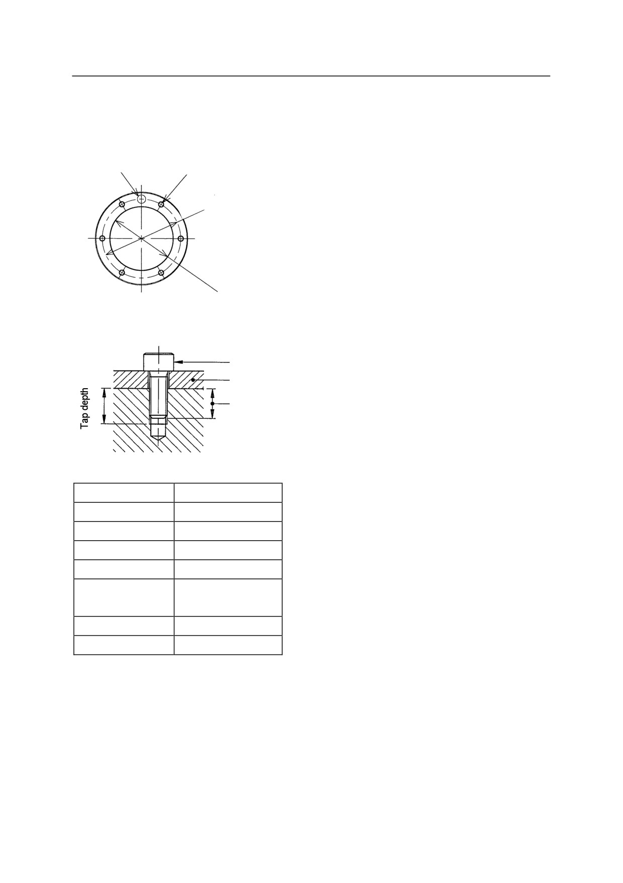
5.4.2 MOUNTING TOOL TO BA SERIES ARM
Dimensions of Wrist End
Pin hole
Tapped holes
D
Positioning hole
Specification of Mounting Bolts
Mounting bolt
Tool
Length of engagement
Tapped holes
6-M4
D
56
Pin hole
6H7 Depth 8
Positioning hole
45H7 Depth 5
Tap depth
8 mm
Length of
6 - 7 mm
engagement
High tension bolt
SCM435, 10.9 min
Tightening torque
3.43 Nm
5-56
5. Installation
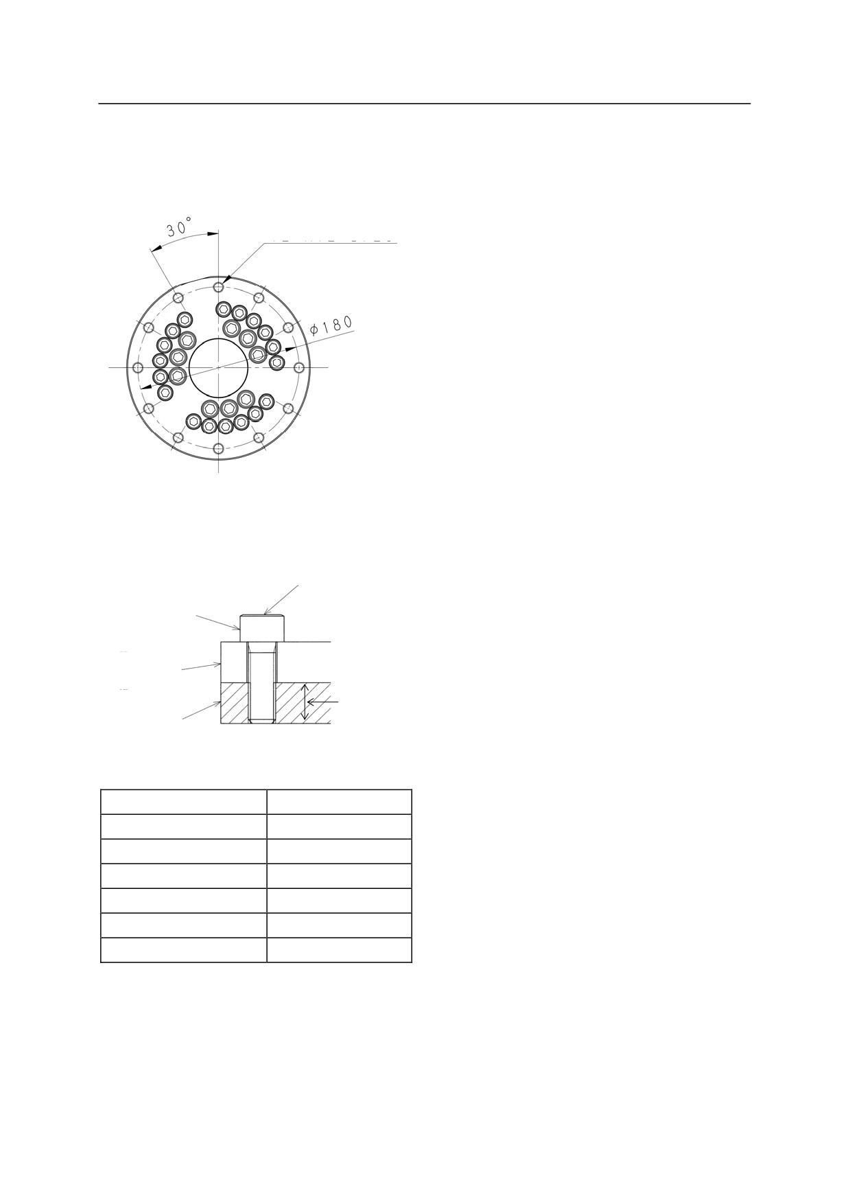
5.4.3 MOUNTING TOOL TO CP SERIES ARM
Dimensions of Wrist End
12-M12 Dp29
Specification of Mounting Bolts
Check tightening
torque
Mounting bolt
Tool
Check length of
engagement
Tool mounting part
(Flange)
Standard flange
Tapped holes
12-M12
D
180
Tap depth
29 mm
Length of engagement
18 - 28 mm
High tension bolt
SCM435, 10.9 min
Tightening torque
98.07 Nm
5-57
5. Installation
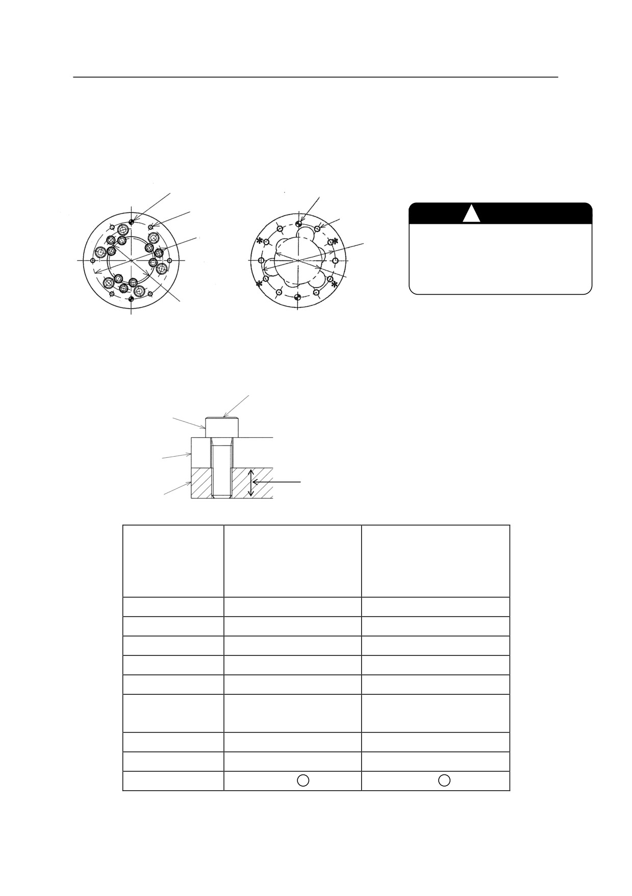
5.4.4 MOUNTING TOOL TO M SERIES ARM
Dimensions of Wrist End (Flange)
MD/MX series
MT400N
Pin holes
Pin holes
Tapped holes
Tapped holes
㸟
CAUTION
D
D
Use at least one pin for assured
fixing to prevent the tool on
Positioning
the flange from moving.
hole
Positioning
hole
Specification of Mounting Bolts
Check tightening torque
Mounting bolt
Tool
Check length of engagement
Tool mounting part
(Flange)
MD400N/ MD500N
Model
MX350L/ MX420L
MT400N
MX500N/ MX700N
Tapped holes
6-M12
6-M10
D
200
160
Pin holes
2-12H7 Depth 12
2-10H7 Depth 12
Positioning hole 㻌
125H7 Depth 8.5
100H7 Depth 8
Tap depth
29 mm
12 mm
Length of
18 - 28 mm
10 - 11 mm
engagement
High tension bolt
SCM435, 10.9 Min
SCM435, 10.9 Min
Tightening torque
98.07 Nm
98.07 Nm
Pin Material
S45C H *
S45CH *
NOTE* S45C thermal refining steel or equivalent in strength
5-58
5. Installation
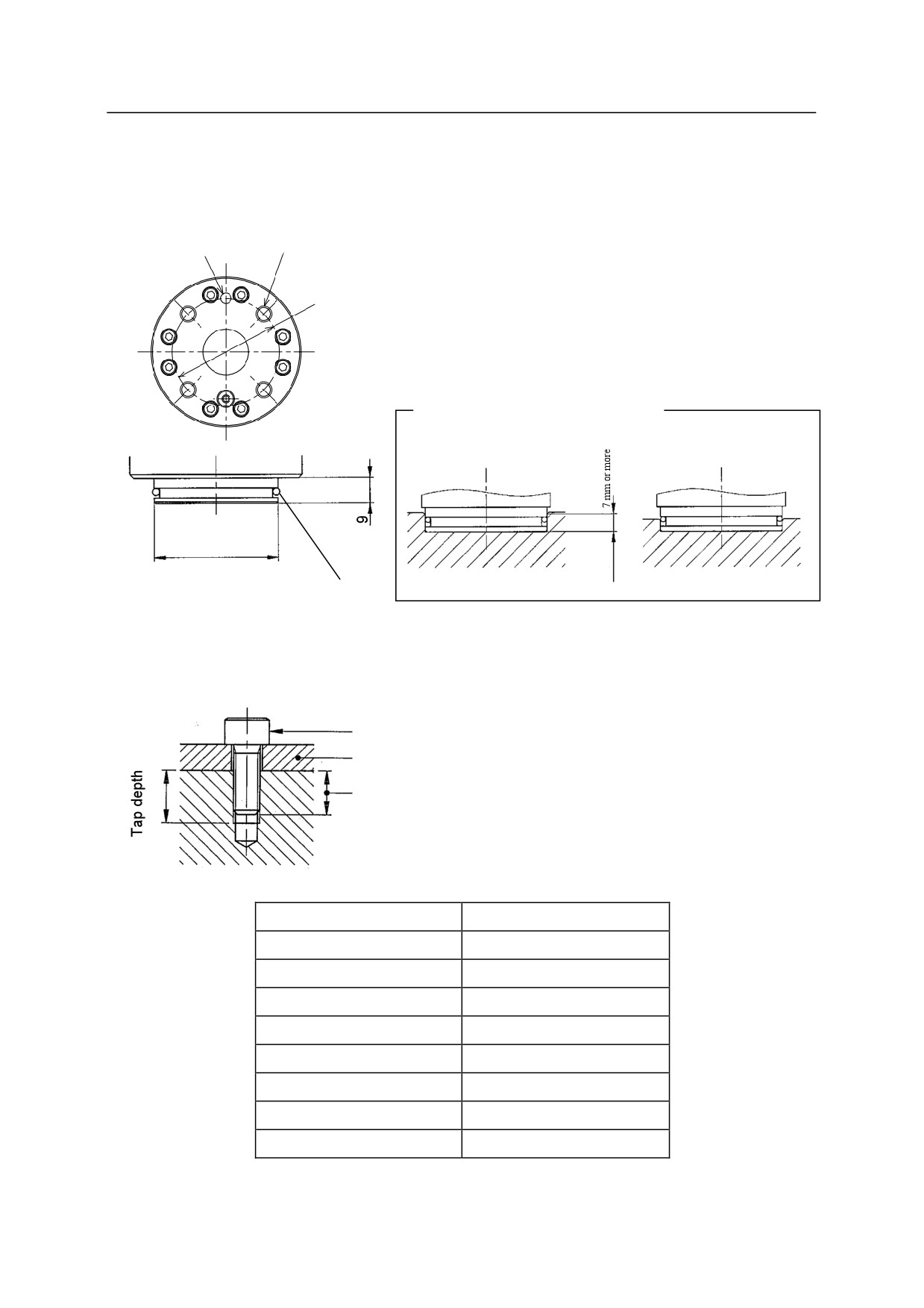
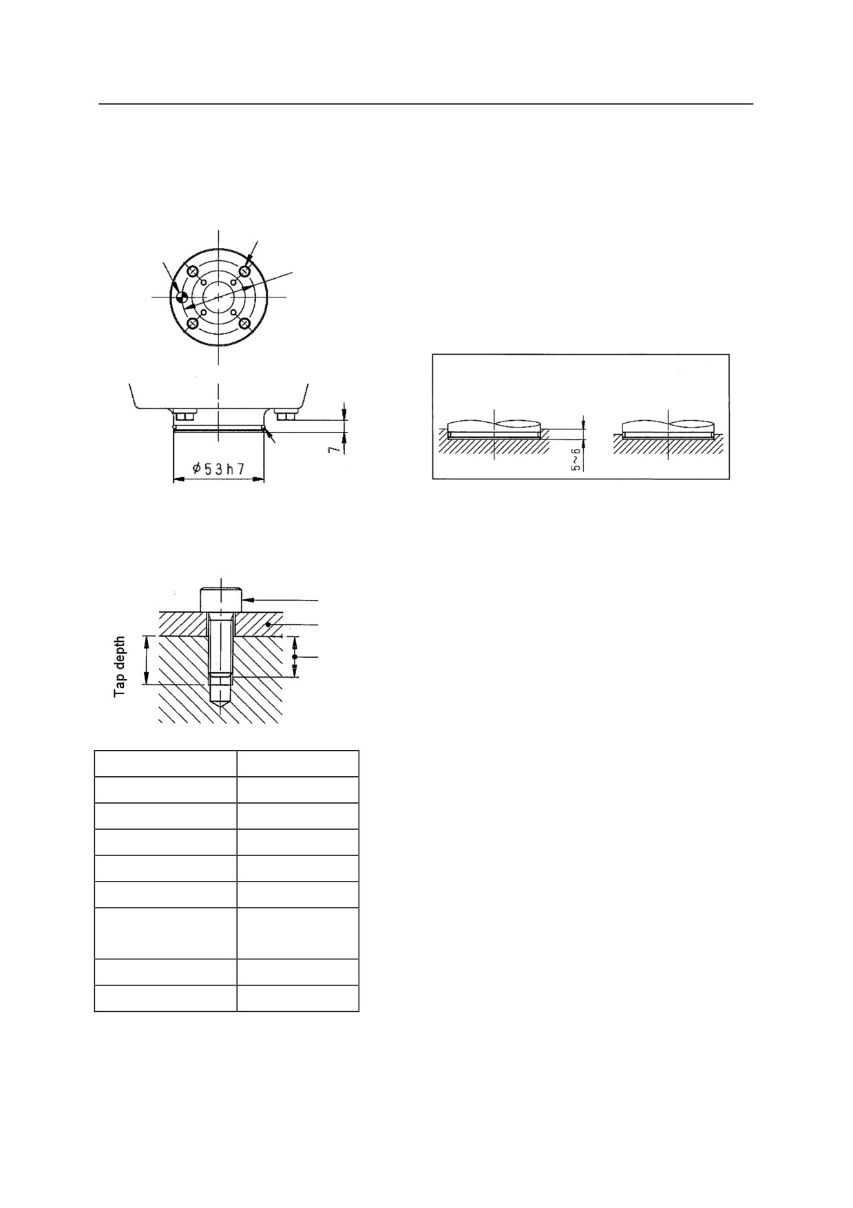
5.4.5 MOUNTING TOOL TO MC SERIES ARM
Dimensions of Wrist End (Flange)
Pin hole
Tapped holes
D
Example of tool mounting
OK
NG
56h7
O-ring
Specification of Mounting Bolts
Mounting bolt
Tool
Length of
engagement
Model
MC004N
Tapped holes
4-M6
D
40
Pin hole
4H7 Depth 6
Positioning hole
56h7
Tap depth
7.5 mm
Length of engagement
5 - 7 mm
High tension bolt
SCM435, 10.9 or more
Tightening torque
12 Nm
5-59
5. Installation
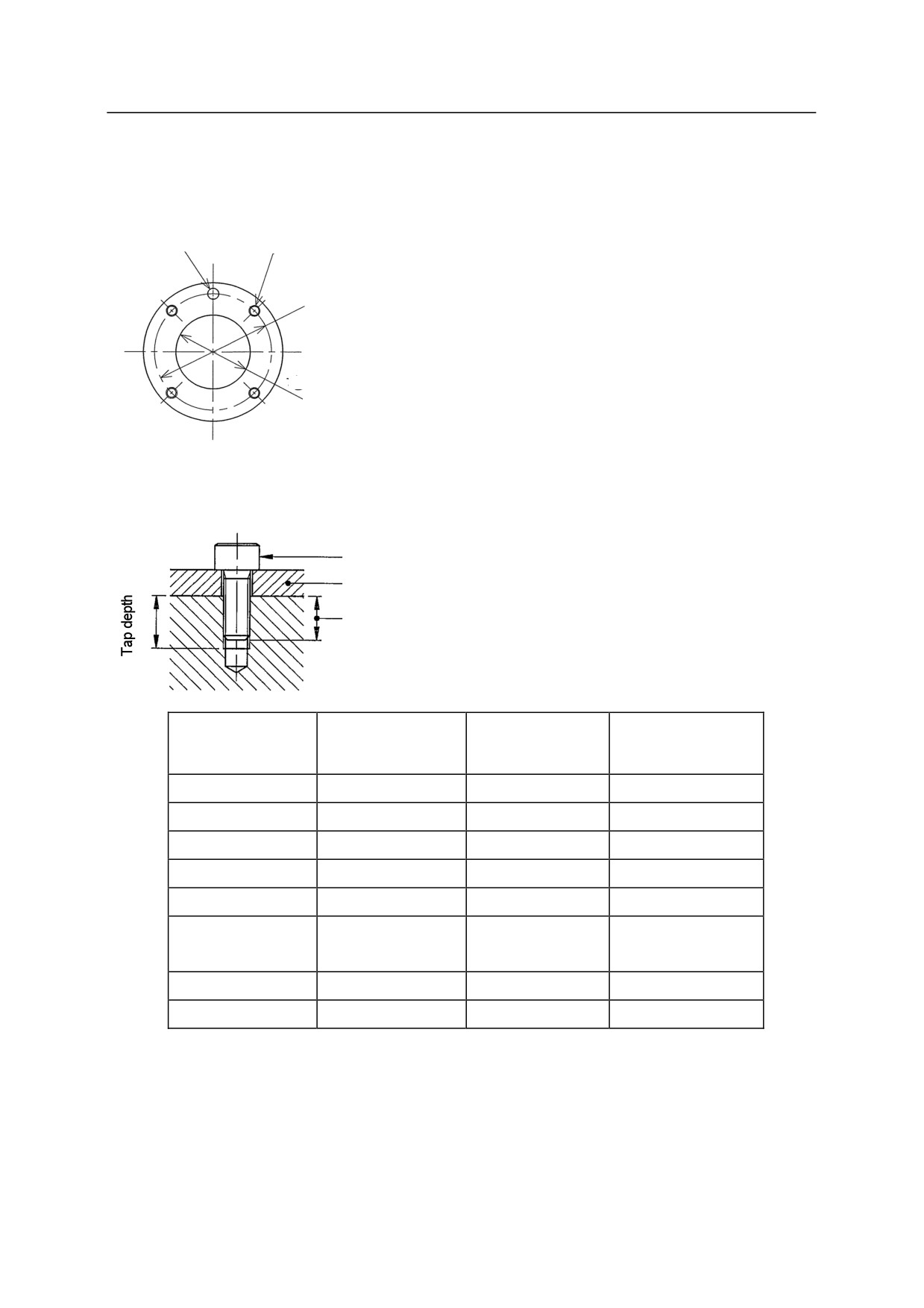
5.4.6 MOUNTING TOOL TO MS SERIES ARM
Dimensions of Wrist End (Flange)
Tapped holes
Pin hole
D
Example of tool mounting
OK
NG
O-ring
Positioning hole
Specification of Mounting Bolts
Mounting bolt
Tool
Length of
engagement
Model
MS005N
Tapped holes
4-M6
D
40
Pin hole
6H7 Depth 12
Positioning hole
53h7
Tap depth
12 mm
Length of
7-9 mm
engagement
Tightening bolt
SUS304
Tightening torque
8.3 Nm
5-60
5. Installation
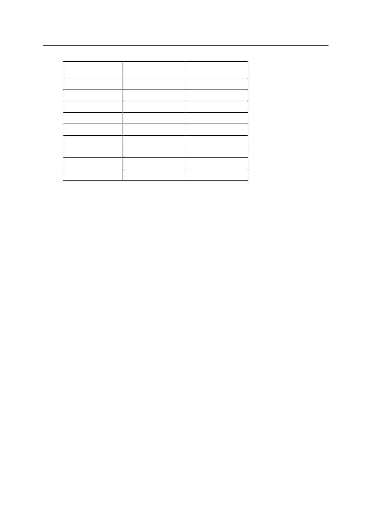
5.4.7 MOUNTING TOOL TO R SERIES ARM
Dimensions of Wrist End
Pin hole
Tapped holes
D
Positioning hole
Specification of Mounting Bolts
Mounting bolt
Tool
Length of engagement
RA10L, RA20N,
RA06L, RA10N,
RC05L, RS05L,
Model
RS10L, RS15X,
RS06L, RS10N
RS05N
RS20N
Tapped holes
4-M6
4-M6
4-M5
D
40
63
31.5
Pin hole
6H7 Depth 6
6H7 Depth 6
5H7 Depth 8
Positioning hole
25H7 Depth 6
40H7 Depth 6
20H7 Depth 3
Tap depth
8 mm
9 mm
8 mm
Length of
6 - 7 mm
7 - 8 mm
6 - 7 mm
engagement
High tension bolt
SCM435, 10.9 min
SCM435, 10.9 min
SCM435, 10.9 min
Tightening torque
11.76 Nm
11.76 Nm
6.86 Nm
5-61
5. Installation
RD80N, RS30N,
Model
RS03N
RS50N, RS80N
Tapped holes
6-M8
4-M5
D
80
31.5
Pin hole
8H7 Depth 8
5H7 Depth 6
Positioning hole
50H7 Depth 6
20H7 Depth 4
Tap depth
13 mm
8 mm
Length of
8 - 12 mm
6 - 8 mm
engagement
High tension bolt
SCM435, 10.9 min
SCM435, 10.9 min
Tightening torque
29.40 Nm
6.86 Nm
5-62
5. Installation
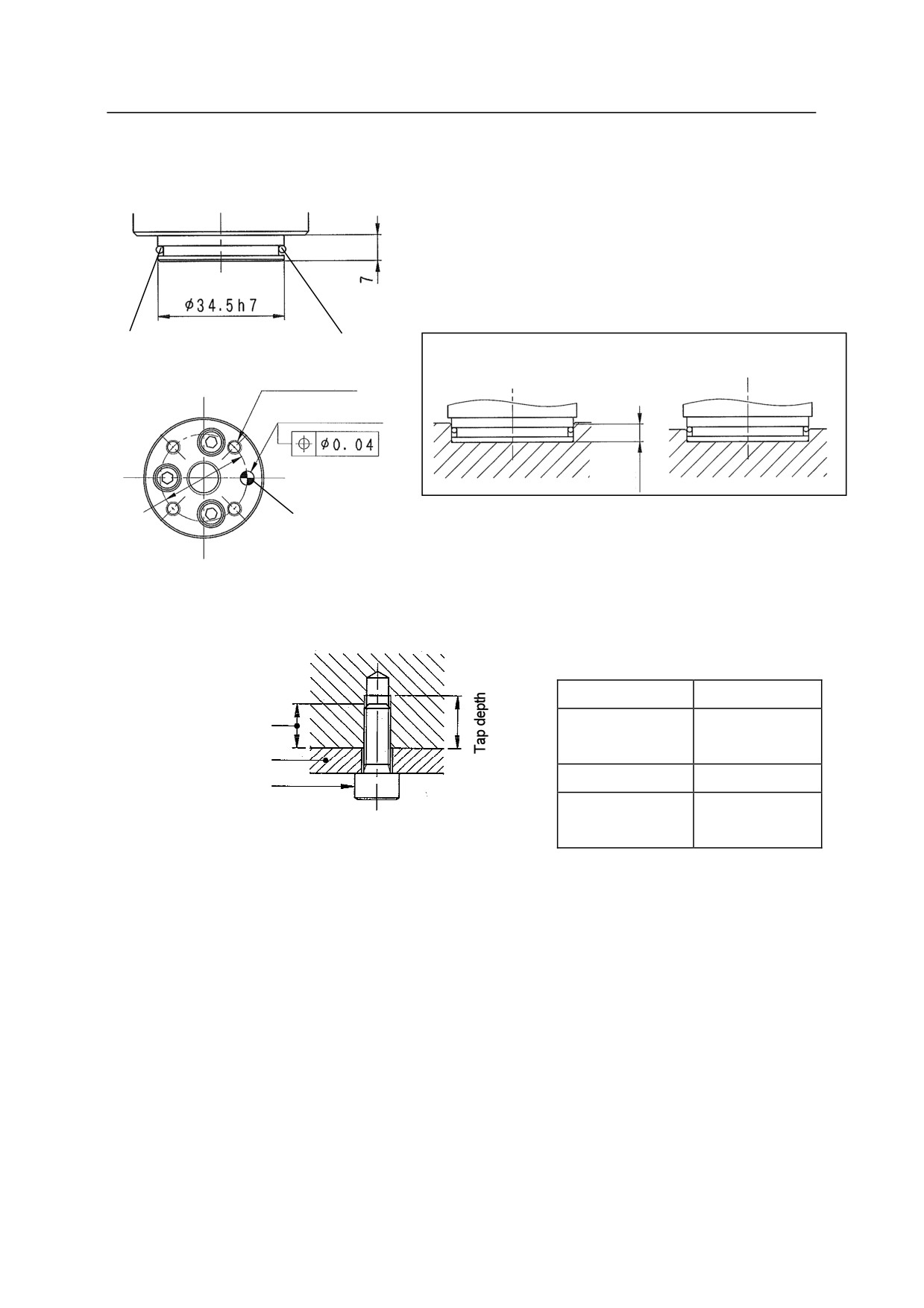
5.4.8 MOUNTING TOOL TO YF SERIES ARM
When using air, the positioning hole depth should
be 5 mm or deeper.
Positioning
O Ring
boss
When using air
4-M4 Dp8
OK
NG
P.C.D. 4H7 Dp5
5 mm
min.
P.C.D. 25
Pin hole
Specification of Mounting Bolts
Tap depth
8 mm
Length of engagement
Length of
6 to 7 mm
engagement
Tool
Bolt
SUS304
Mounting bolt*
Tightening
2.4 N-m
torque
5-63
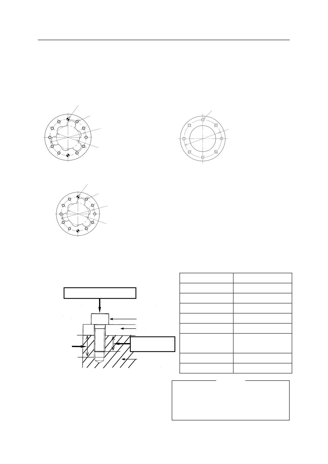
5. Installation
5.4.9 MOUNTING TOOL TO Z SERIES ARM
Dimensions of Wrist End (Flange)
ZB Series
ZD Series
Pin hole
Drill holes
Tapped holes
x
x
D
D
x
x Positioning hole
ZH/ZT/ZX Series
Pin holes
Tapped holes
D
* Positioning hole
NOTE:
4 tapped holes marked * require no tightening.
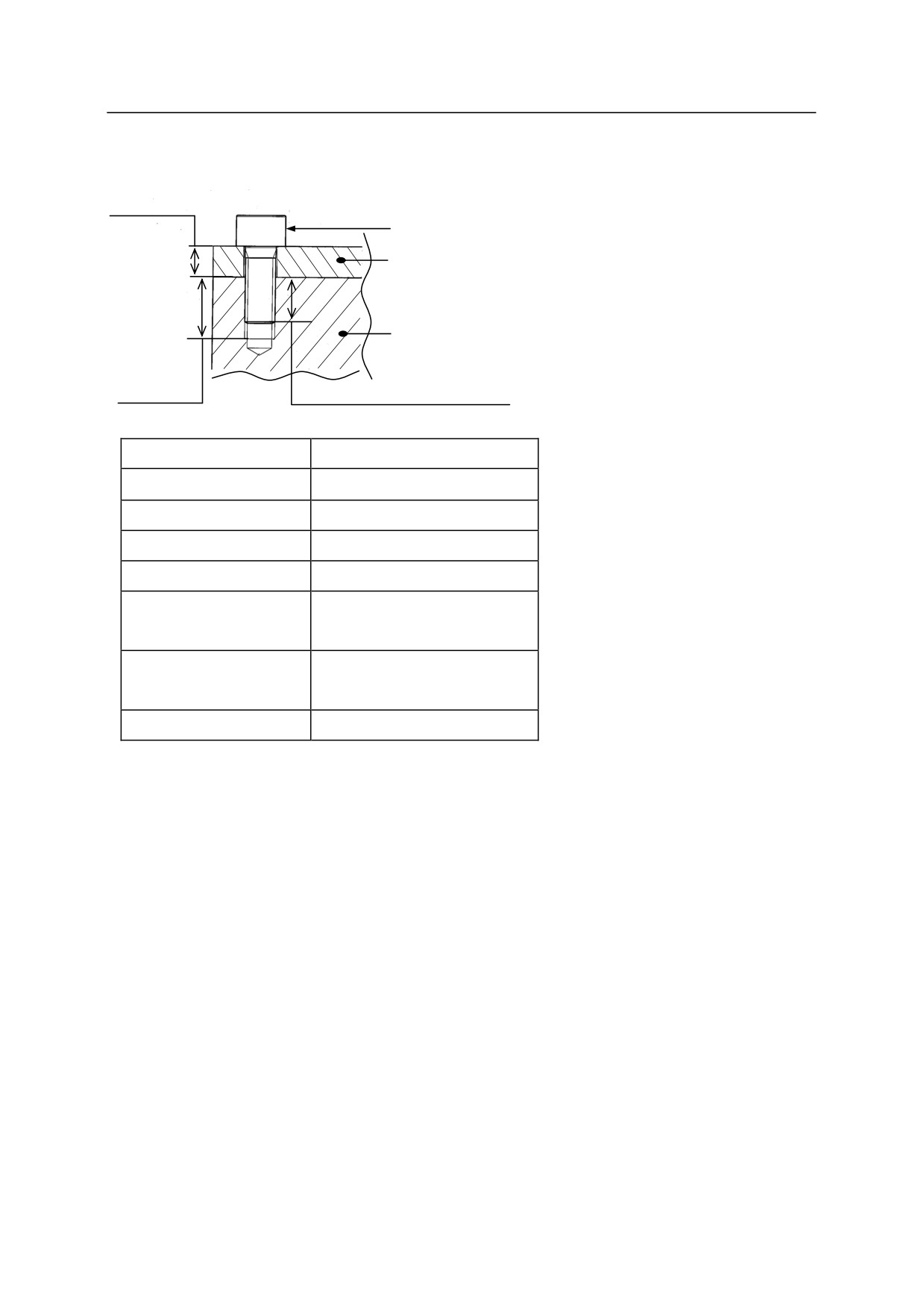
Specification of Mounting Bolts
ZB Series
Model
ZB150S
Tapped hole
6-M10
Check tightening torque
D
125
Pin hole
2-10H7 Depth 12
Mounting bolt
Positioning hole
80H7 Depth 8
Tool
Tap depth
12 mm
Length of
Check length
Check tap depth.
10-11 mm
of engagement
engagement
Tool mounting
High tension bolt
SCM435, 10.9 min
part (flange)
Tightening torque
56.84 Nm
[ NOTE ]
The above mounting sizes are based on ISO.
If non-ISO sizes are used, insert the adapter
plate (option) prior to mounting tools.
5-64
5. Installation
ZD Series
Check flange
Check tightening
thickness.
torque.
Mounting bolt
Tool mounting
part (flange)
Tool
Check tap
depth.
Check length of engagement
Model
ZD130S, ZD250S
Drill holes
8-11 (M10).
D
150
Pin holes
-
Positioning hole
-
Arm flange thickness
15 mm
SCM435,
High tension bolt
10.9 Min
Tightening torque
56.84 N-m
5-65
5. Installation
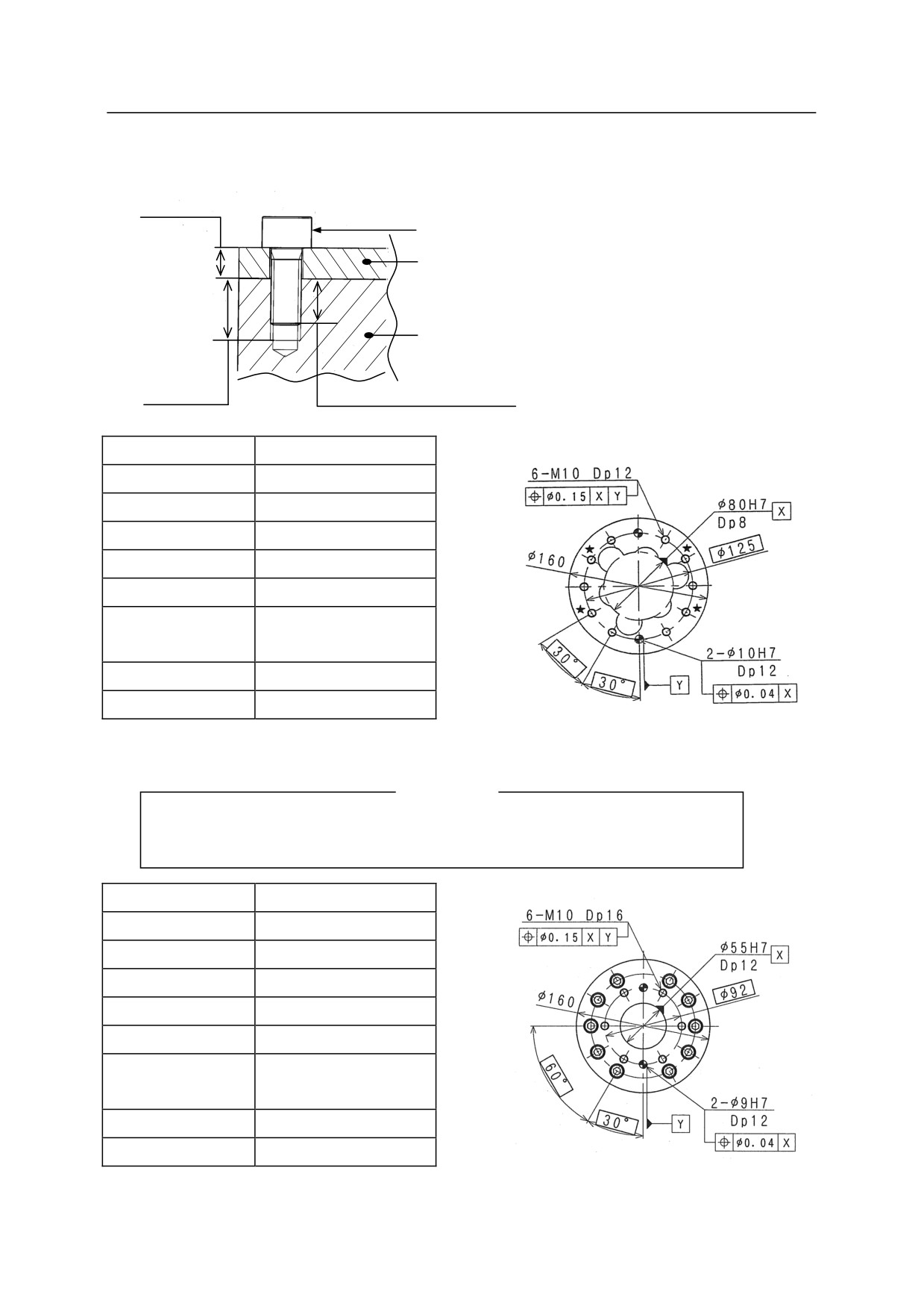
ZH Series
Check flange
thickness.
Check tightening
torque.
Mounting bolt
Tool
Tool mounting part (flange)
Check tap
Check length of engagement.
depth.
Model
ZH100U
Tapped holes
6-M10
D
125
Pin holes
2-10H7 Depth 12
Positioning hole
80H7 Depth 8
Tap depth
12 mm
Length of
10 - 11 mm
engagement
High tension bolt
SCM435, 10.9 min
Tightening torque
56.84 Nm
NOTE:
4 tapped holes marked * require no tightening.
[ NOTE ]
The above mounting sizes are based on ISO. For the sizes below, insert the
adapter plate (option) prior to mounting tools.
Model
ZH100U
Tapped holes
6-M10
D
92
Pin holes
2-9H7 Depth 12
Positioning hole
55H7 Depth 12
Tap depth
16 mm
Length of
14 - 15 mm
engagement
High tension bolt
SCM435, 10.9 min
Tightening torque
56.84 Nm
5-66
5. Installation
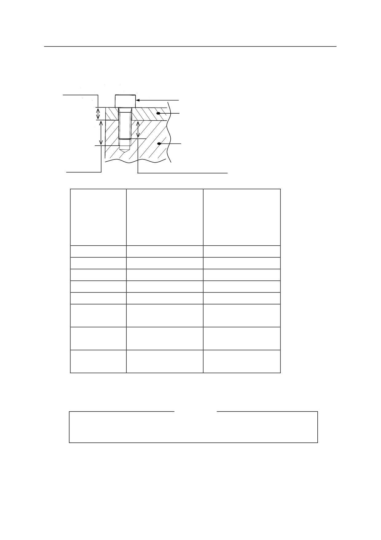
ZT/ZX Series
Check flange
thickness.
Check tightening
torque.
Mounting bolt
Tool
Tool mounting
part (flange)
Check tap
depth.
Check length of engagement.
ZT130L, ZT130S,
ZT130U, ZT165U,
ZT200S, ZX200S,
Model
ZT200U, ZX130L,
ZX300S
ZX130S, ZX130U,
ZX165U, ZX200S
Tapped holes
6-M10
6-M10
D
125
160
Pin holes
2-10H7 Depth 12
2-10H7 Depth 12
Positioning hole
80H7, Depth 8
100H7, Depth 8
Tap depth
12 mm
12 mm
Length of
10 - 11 mm
10 - 11 mm
engagement
High tension
SCM435,
SCM435,
bolt
10.9 Min
10.9 Min
Tightening
56.84 Nm
56.84 Nm
torque
[ NOTE ]
The above mounting sizes are based on ISO. For the sizes below, insert the
adapter plate (option) prior to mounting tools.
5-67
5. Installation
ZT130L, ZT130S, ZT130U,
ZT165U, ZT200U, ZX130L,
ZT200S, ZX200S,
Model
ZX130S, ZX130U, ZX165U,
ZX300S
ZX200S
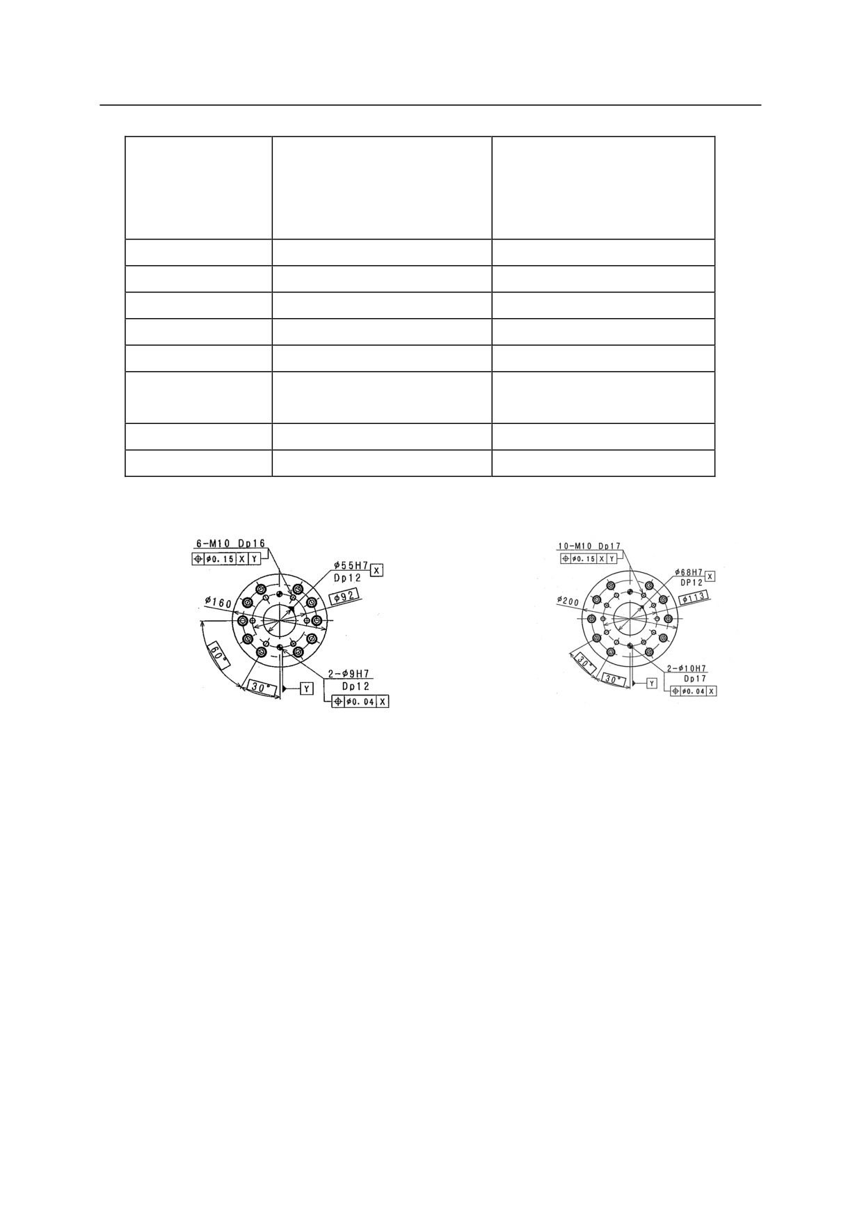
Tapped holes
6-M10
10-M10
D
92
113
Pin holes
2-9H7, Depth 12
2-10H7, Depth 17
Positioning hole
55H7, Depth 12
68H7, Depth 12
Tap depth
16 mm
17 mm
Length of
14 - 15 mm
15 - 16 mm
engagement
High tension bolt
SCM435, 10.9 Min
SCM435, 10.9 Min
Tightening torque
56.84 Nm
56.84 Nm
5-68
6. Connection
6.0 CONNECTION
6.1 PRECAUTIONS FOR ROBOT CONNECTION
!
WARNING
Do not connect the external power until connections between controller and robot
are complete. Accidents, such as electric shock may occur.
!
CAUTION
1. When connecting the harnesses, be sure to use the correct harnesses. Using an
incorrect harness, or misconnecting the harness may damage connectors or cause a
break in the electrical system.
2. Use conduits, ducts, etc. to prevent people or equipment (forklift etc.) from stepping
on or riding over the signal and motor harness lines. Otherwise, an unprotected
harness may become damaged causing breaks in the electrical system.
3. Even when the harnesses are long, do not bundle them winded or bended.
Bundling the harness causes the heat to build up in the harness, resulting in
over-heat and furthermore may cause fire.
4. Separate the harnesses from any nearby high voltage lines (min. 1 m apart). Do
not bundle or run the harnesses in parallel with other power lines. Otherwise, the
noise generated from power lines will cause malfunctions.
5. Separate the motor harness from the communication and sensor cables, and
distribute the lines so they are neither bundled nor running in parallel. Moreover,
connect the communication and sensor cables using shield mesh wire that includes
twisted pair lines and connect the mesh wire to an adequate FG terminal.
Otherwise, PWM noise radiated from the robot’s motor drive lines may penetrate
into various cables, such as communication cable and cause communication errors.
6. Separate the welder secondary cable from the robot’s signal harness. Do not wire
them in the same duct.
7. The motor harness (power line) between the robot and controller will generate
PWM noise due to the PWM control driving the motors. This noise may cause
interference with signal lines. Prevent interference using these countermeasures:
(1) Separate the power and signal lines as much as possible.
(2) Use the shortest possible length for the power line.
(3) Avoid bundling, wiring in parallel the power and signal lines as much as
possible.
(4) Do not wire the power and signal line within the same duct/conduit.
(5) Set and secure a firm earth line connection for the controller.
6-1
6. Connection
6.2 CONNECTING BETWEEN CONTROLLER AND ROBOT
6.2.1 CONTROLLER SIDE
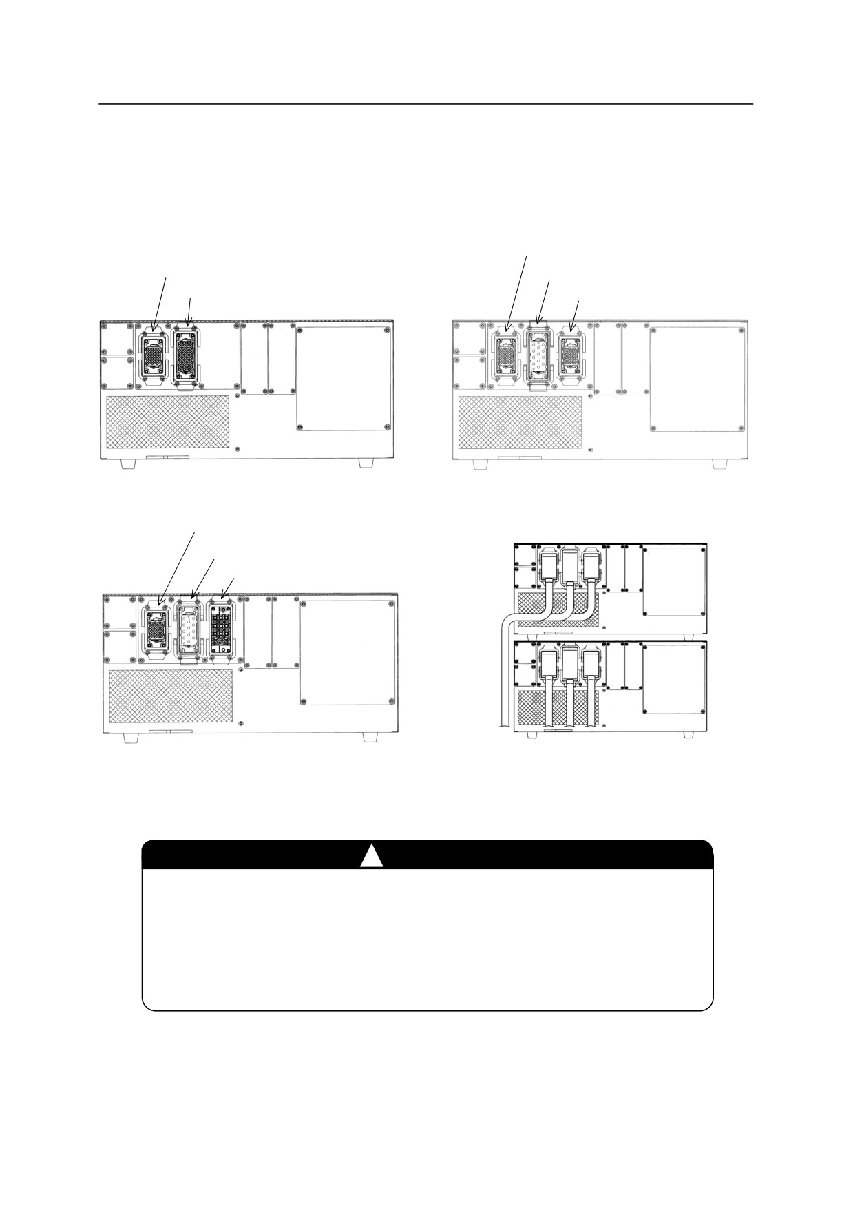
E0x controller
Signal harness (X3)
Signal harness (X3)
Major axis motor harness (X4)
Motor harness (X4)
Wrist axis motor harness (X5)
E01 controller
E02 controller
Signal harness (X3)
Major axis motor harness (X4)
Wrist axis motor harness (X5)
E03/E04 controller
Double stack arrangement
of controllers
!
CAUTION
1. Fix each connector securely. The robot may malfunction if connectors
loosen or detach.
2. When placing a controller on another controller, connect the separate
harnesses so that they do not block the exhaust port of the bottom
controller.
6-2
6. Connection
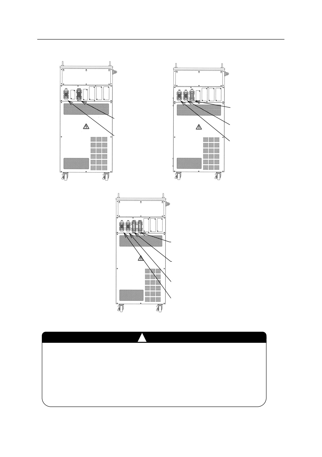
E4x controller
Connector for major axis
motor harness (X4)
Connector for motor
harness (X4)
Connector for wrist axis
motor harness (X5)
Connector for signal
harness (X3)
Connector for signal
harness (X3)
E40 controller
E42/E43 controllers
Connector for wrist axis
motor harness (X4-2)
Connector for major axis motor
harness (X4-1)
Connector for brake and JT7 motor
harness (X5)
Connector for signal
harness (X3)
E44 controller
!
CAUTION
1. Fix each connector securely. The robot may malfunction if connectors
loosen or detach.
2. The harness should drop straight down from the connector. Because
connectors are located at the upper part of controller, if the connected
harnesses are pulled to the controller side or rear direction, the controller
might be toppled.
6-3

6. Connection
E70/E71 controllers
X4
X3
Signal harness
Keep space for reasonable treatment
Motor harness
of harnesses with straight connectors.
E91 controller
Motor harness (X4)
Signal harness (X3)
!
CAUTION
Fix each connector securely. The robot may
malfunction if connectors loosen or detach.
6-4
6. Connection
6.2.2 ARM SIDE
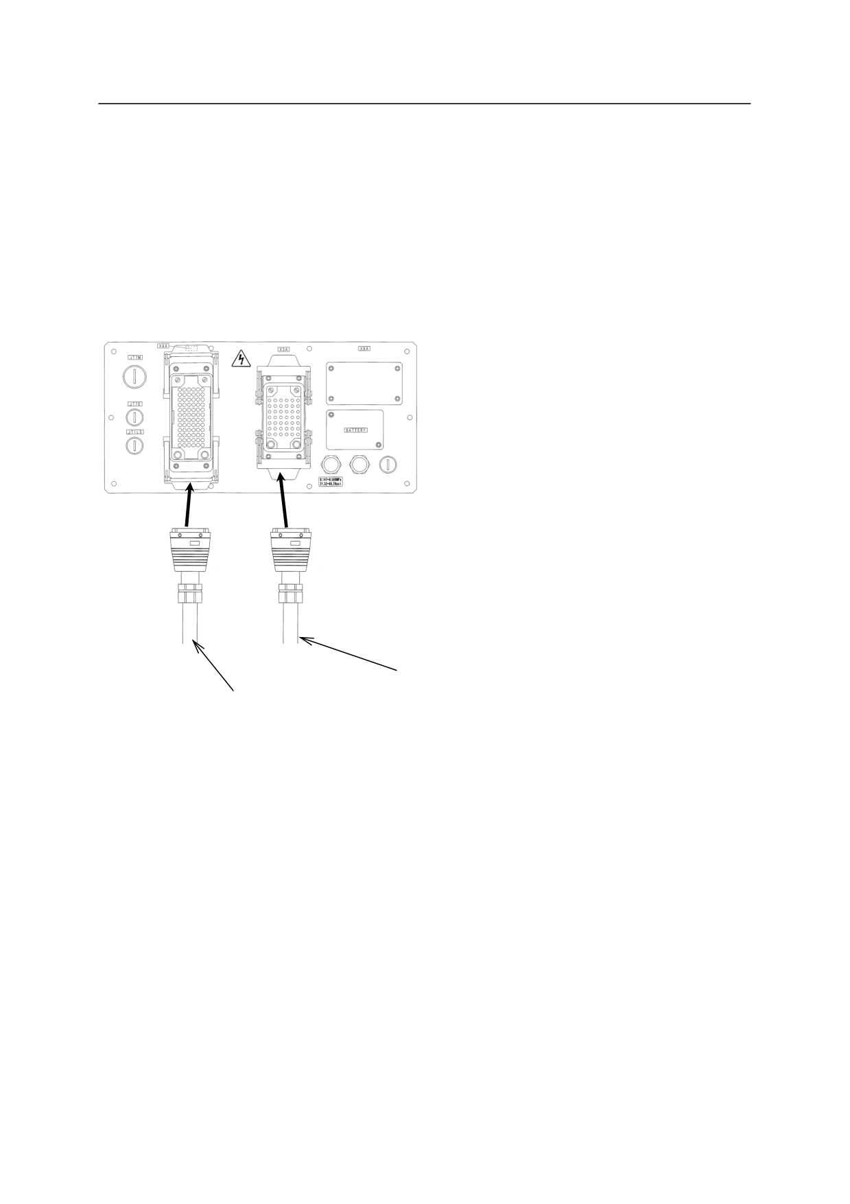
Match the name of the connector on the controller side and arm side to connect the harnesses
correctly. The controller side and arm side connectors are distinguished by an “A” placed at the
end of the name of the arm connector. The connectors on the controller side are named without
the “A”. Below figure shows RS20 as an example.
RS20
X4A
X3A
Signal harness
Motor harness
6-5
6. Connection
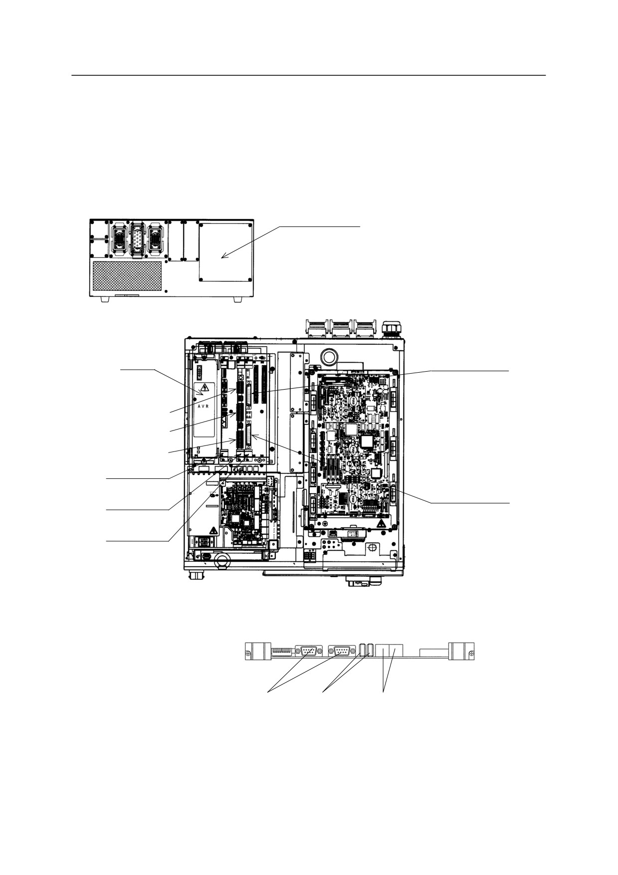
6.3 CONNECTING PERIPHERAL CONTROL EQUIPMENT
According to application specifications, connect respective connectors in the controller shown
below with the peripheral controller or devices.
E0x controller
I/O signal inlet
Connect each connecting port
with peripheral equipment and
devices, using the I/O signal
inlet on the rear side of the
controller.
External D-I/O
Connector CN2
AVR
(Output)
Terminal block X7
Terminal block X8
Terminal block X9
External D-I/O
1VA Board
Connector CN4
(Input)
1TR Board
1TW Board
Top
See the figure on the
right for details on
connecting ports of
1VA board.
RS-232C port* USB port*
Ethernet port*
NOTE*: The left RS-232C port, the left USB port and the left Ethernet port are
connected to each port in the accessory panel for standard specification.
6-6
6. Connection
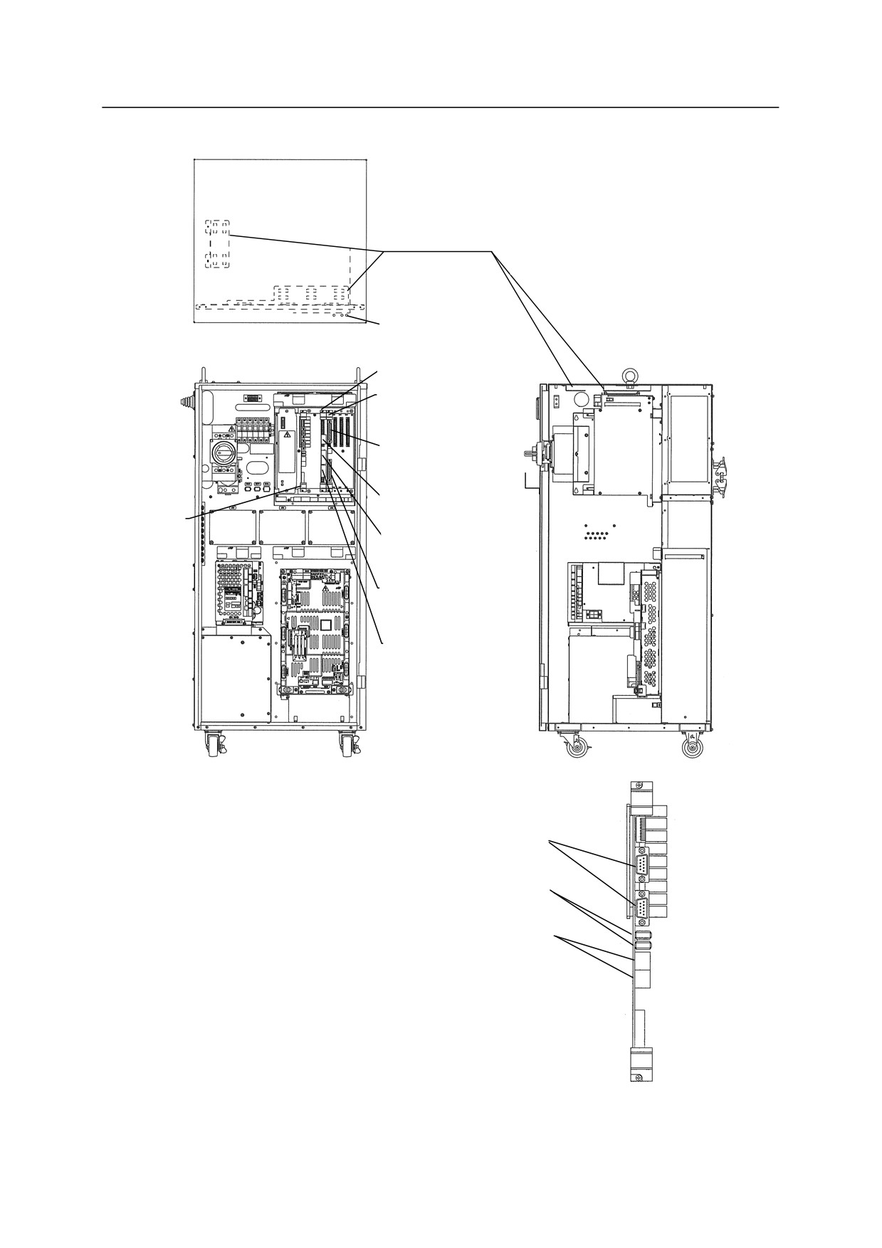
Kawasaki Robot
Instruction Manual
E4x controller
Use cable support for wiring of
24Vdc or less such as I/O, Ethernet
and fieldbus cable etc. Make sure
not to put any stress on connectors on
Cable support
each board.
Screw to connect
external I/O Cable
shield (M4)
1TR Board
1TW Board
External D-I/O
Connector CN2
(Output)
Terminal block
1TA/1VA
X7 Connector
Board
Terminal block
X8 Connector
External D-I/O
Connector CN4
(Input)
Terminal block
X9 Connector
See the figure on the right for
details on connecting ports of
1TA/1VA board.
RS-232C port*
USB port*
Ethernet port
NOTE*: The upper RS-232C port and the upper USB port are
connected to the each port in the accessory panel for
standard specification.
6-7
6. Connection
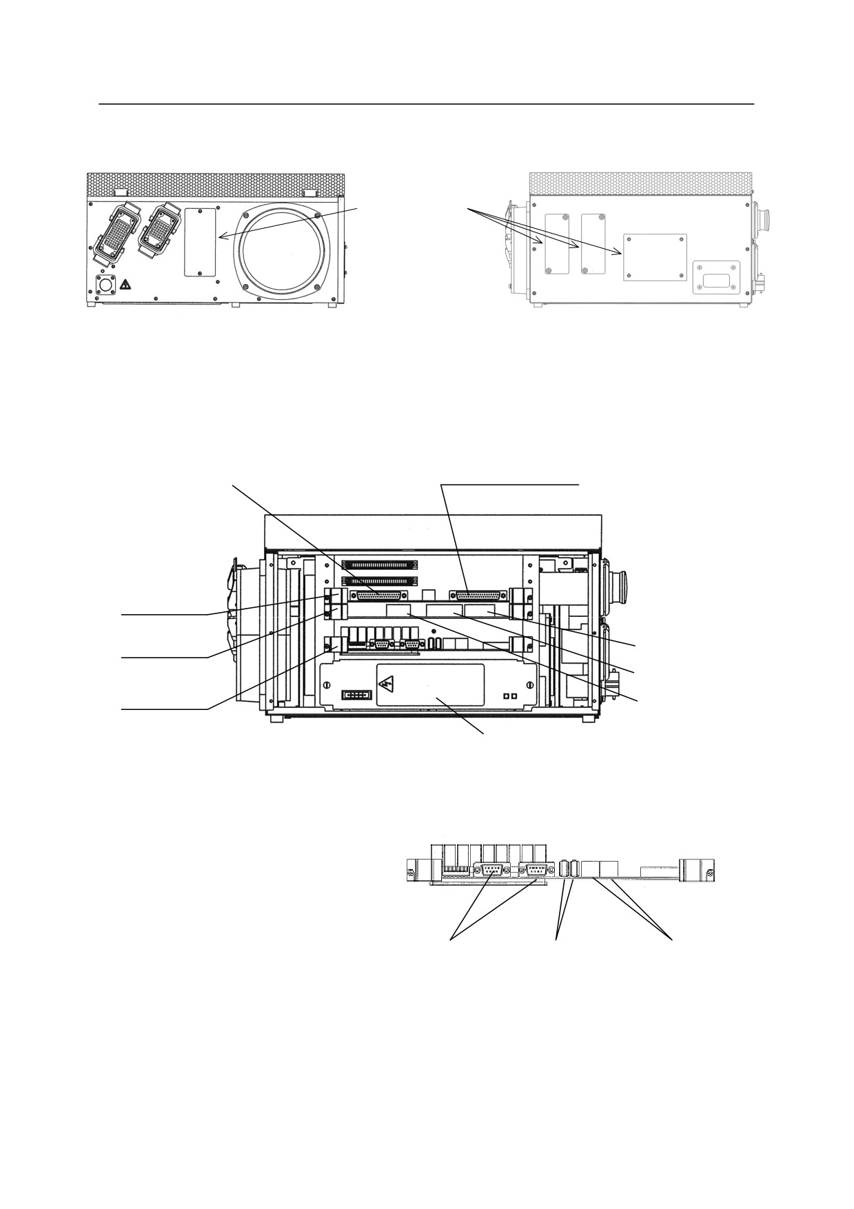
E70/E71 controllers
I/O signal inlet
Connect each
connecting port with
peripheral equipmen
and devices, using
the I/O signal inlet on
Rear
Left
the rear or the left
side of the controller.
External D-I/O
External D-I/O
Connector CN2 (Output)
Connector CN4 (Input)
1TW Board
Terminal block X9
1TR Board
Terminal block X8
1TA/1VA
Terminal block X7
Board
AVR
Left
See the figure on the right for
details on connecting ports of
1TA/1VA board.
RS-232C port*
USB port*
Ethernet port
NOTE*: The left RS-232C port and the left USB port are
connected to each port in the accessory panel for
standard specification.
6-8
6. Connection
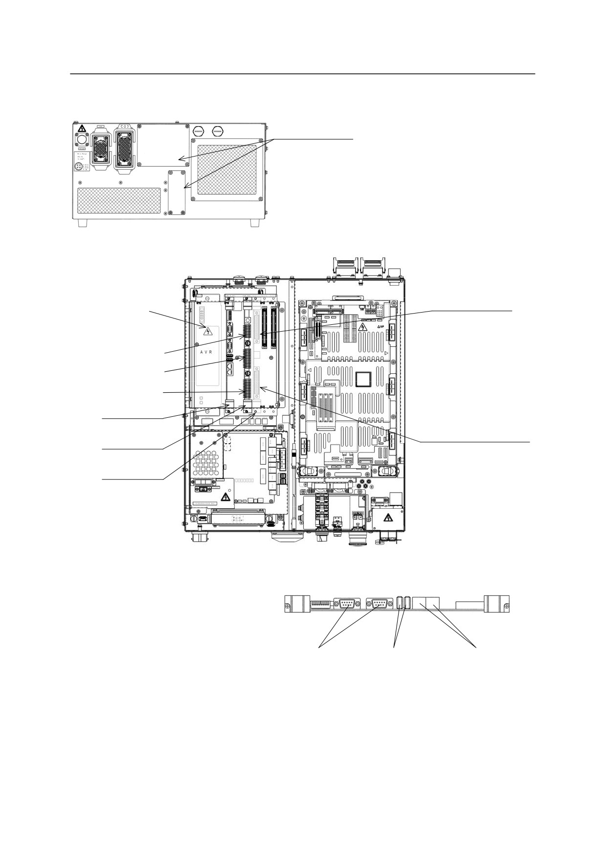
E91 controller
I/O signal inlet
Connect each connecting port
with peripheral equipment and
devices, using the I/O signal
inlet on the rear side of the
controller.
External D-I/O
Connector CN2
(Output)
AVR
Terminal block X7
Terminal block X8
Terminal block X9
1VA Board
External D-I/O
Connector CN4 (Input)
1TR Board
1TW Board
Top
See the figure on the right for
details on connecting ports of 1VA
board.
RS-232C port*
USB port*
Ethernet port
NOTE*: The left RS-232C port and the left USB port are
connected to each port in the accessory panel for
standard specification.
6-9
6. Connection
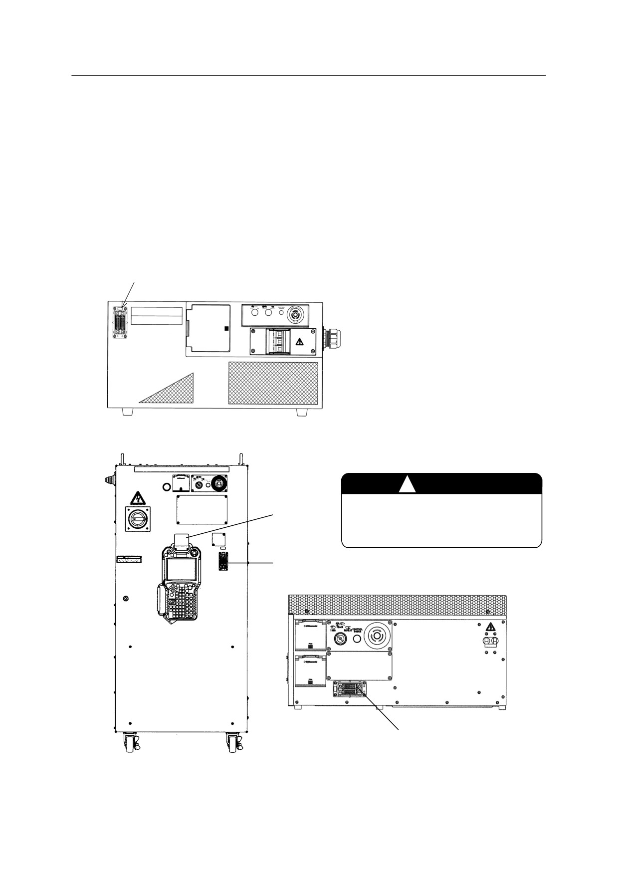
6.4 CONNECTING BETWEEN CONTROLLER AND TEACH PENDANT
1. Connect the teach pendant cable with the connector located below the operation panel.
Pull up the lever and insert the cable side connector, and then pull down the lever to lock the
connectors.
2. Hang the teach pendant and the teach pendant cable on the hook.
(No hook is provided for
E0x/E70/E71/E91 controllers.)
Teach pendant connector
E0x controller
CAUTION
!
The hook should only be used for
Hook
hanging the teach pendant or cable.
Teach pendant connector (X1)
Teach pendant connector
E70/E71/E91 controllers
E4x controller
This figure shows E70/E71 controllers.
6-10
6. Connection
6.5 CONNECTING THE EXTERNAL POWER
Strictly observe the following precautions when connecting the external power.
!
DANGER
Before beginning the connection work, confirm that the external power supply for the
controller is cut off at the source. To prevent external power from being turned ON
accidentally, tag the breaker and indicate clearly that work is in progress. Or, assign a
supervisor in front of the breaker until all the connections are complete. Connecting
components while power is supplied is extremely dangerous and may cause electric shock.
!
WARNING
1. Confirm that the connected supplying power to the controller meets specifications
shown on the rating plate. In addition, when using the transformer unit*, confirm
the connected supply power meets specifications shown on the label attached on the
side of the transformer unit and connect the voltage switching connector (X601) in
accordance with the voltage specifications. Supplying out-of-specification power
will damage electric components in the controller.
2.
Earth the controller to prevent against electrical noise and shock.
3.
Use dedicated earth wire (100 or less), which is equal to or larger than the
recommended power cable size (3.5 - 8.0 mm2).
4.
Never share an earth line with workpiece to be welded or another machine (weld
machine, etc.).
5.
In arc welding applications, connect the negative pole of the weld power supply to a
jig or directly to workpiece to be welded. Insulate the robot body and controller so
that they do not share a common earth line.
6.
Before turning ON the external power to controller, make sure the power supply
wiring is complete and all the covers are reattached properly. Failure to do so may
cause electric shock.
NOTE* Only E0x controller
6-11
6. Connection
CAUTION
!
! CAUTION
1. Prepare external power that meets the specifications of the controller in terms of
momentary power interruption, voltage fluctuation, power capacity, etc. If the power
is interrupted or the voltage goes out of the controller’s specified range (above/below
ratings), then the power monitoring circuit activates cutting off the power, and an error
is returned.
2. If the external power emits excessive electrical noise, set up a noise filter to reduce the
interference.
3. PWM noise from robot motor lines may cause malfunction of low noise- resistant
devices* via external power line. Confirm that there are no such devices in the
vicinity.
4. Install a separate external power switch (breaker) for the robot, independent and
unconnected to the weld machine.
5. To prevent shorting or accidental leakage on the external power switch, install an earth
leakage breaker.
(Use a time delay type with sensitivity of 100 mA or more.) Also,
use a time-delay-type earth leakage breaker with sensitivity of 100 mA or more when
using a transformer unit.
6. If there is a possibility that surge voltage such as lightning surge might be applied from
external power line, decrease the surge voltage level by mounting a surge absorber.
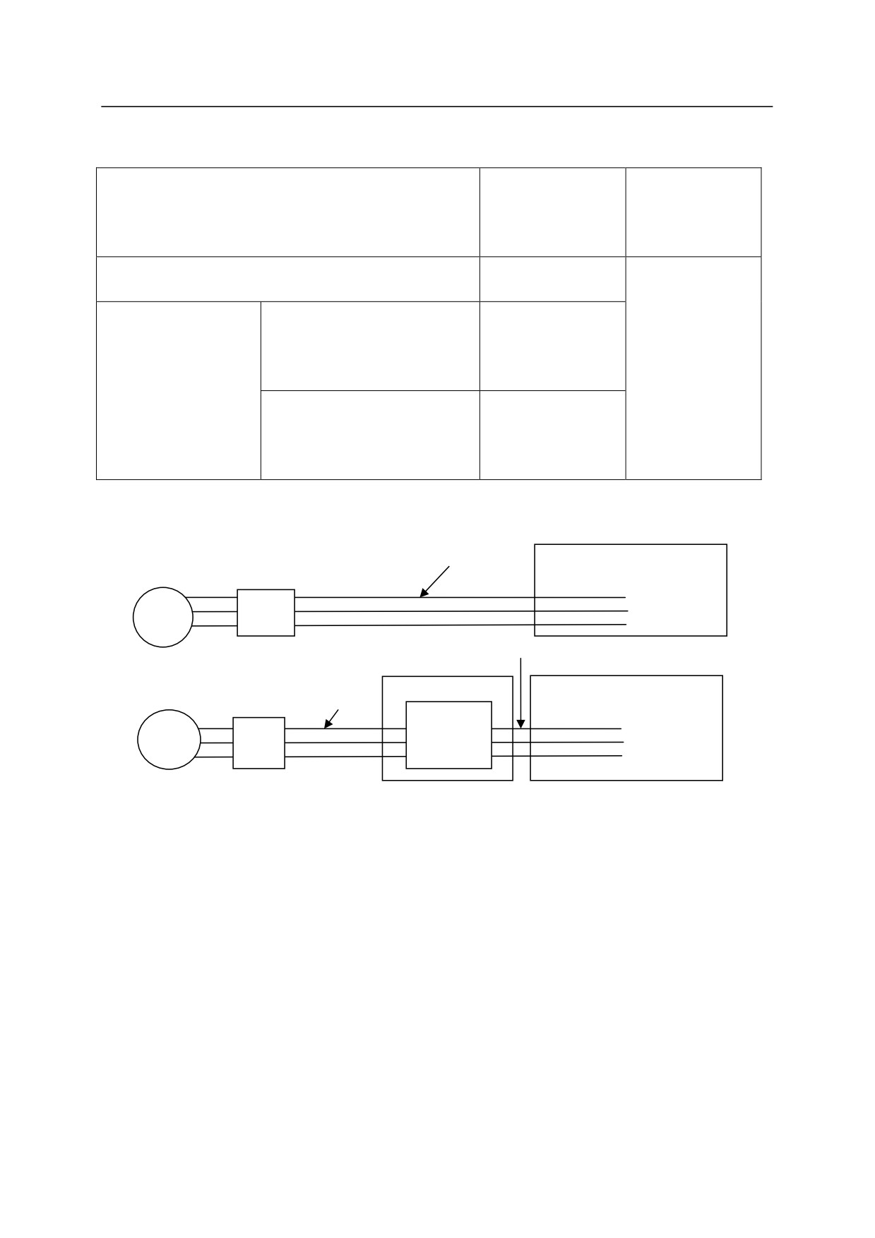
7. For the controller with electric power regeneration function (E03), the AC line voltage
of breaker on the secondary side may increase up to the peak value in the table below if
the power breaker supplying the AC power to the controller (NFB in the figure below)
is cut. Mind this when other equipment shares the common power from the same
breaker with the controller.
NOTE* Proximity switch directly connected with power line etc. may suffer from the
influence.
6-12
6. Connection
Power supplied to the controller
Peak value of line
Peak value of
voltage at point A
line voltage at
(400 V system)
point B (200 V
(V)
system) (V)
䐟Without transformer unit *For AC200-220V
380 V 10 ms or
less
䐠With transformer
When the power source
700 V 10 ms or
unit
setting inside the transformer
less
unit (X601 connector) is on
380 V 10 ms or
380V - 415 V side
less
When the power source
800 V 10 ms or
setting inside the transformer
less
unit (X601 connector) is on
440V - 480 V side
(Without transformer unit)
(B)200 V
E03 controller
system
NFB
AC power
(B)200 V system
(A)400 V
(With transformer unit)
Transformer unit
E03 controller
system
Transformer
NFB
AC power
6-13
6. Connection
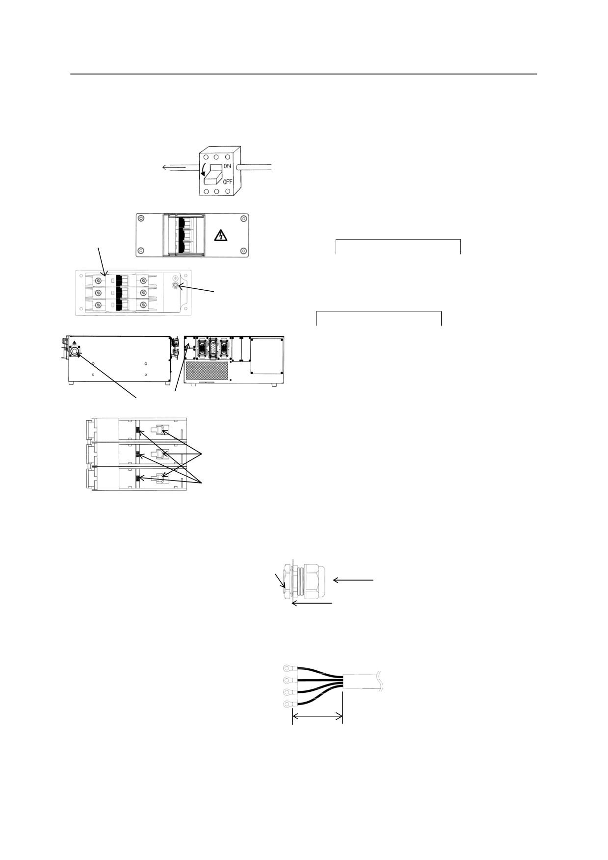
E0x controller
Without transformer unit
Connect the external power according to the
Connect with the
following procedure.
external power
circuit breaker at
the installation
1.Turn OFF the external power for the
site.
OFF
controller.
Breaker
2.Set
CONTROLLER POWER switch on the
controller to the OFF side without fail.
Ground wire
connecting
3.Open the front cover of
screw
CONTROLLER POWER switch.
4.Feed the external power cable into the inlet
on the right or rear side of controller.
External power inlet
5.Connect the power cable to the part shown in
the right figure and the ground wire to the
art shown in the above figure.
Bar-shaped terminal
connection
Round/Y-shaped
Right side of breaker
terminal connection
y
Seal connector for external power inlet is provided on the right side of controller. Use the
power cable whose diameter is 16-22.
Lock nut
Cable
Controller cabinet
y
When inserting the power cable from the right side of controller, the stripped length of cable
sheath should be between 60 and 70 mm.
60-70 mm
y Use crimp-type terminals to connect to the breaker. When using round/Y-shaped terminal,
use the terminal for M5 screw.
6-14
6. Connection
NOTE*: If the cable diameter is more than 22, prepare a seal connector which is
appropriate for the cable diameter. The hole diameter of the plate for external
power inlet is 34.
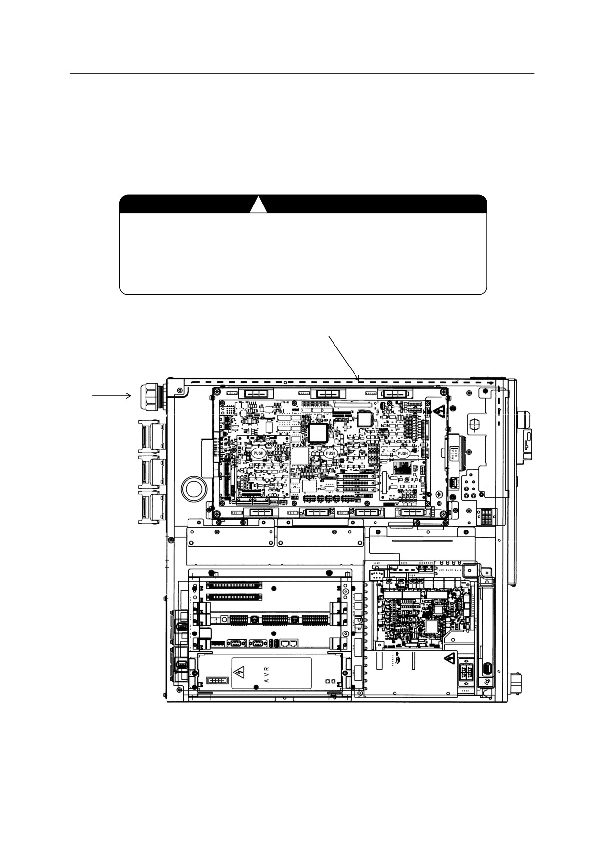
y When inserting the external power cable from rear side, wire the cable along the route
shown in the figure below.
!
CAUTION
1. Confirm current requirements and select a power cable with
adequate capacity.
2. Do not install wire that is too small in diameter, the voltage may
drop or the cable may overheat.
Wiring route when inserting external power cable from rear side
Cable
insertion
from rear side
6-15
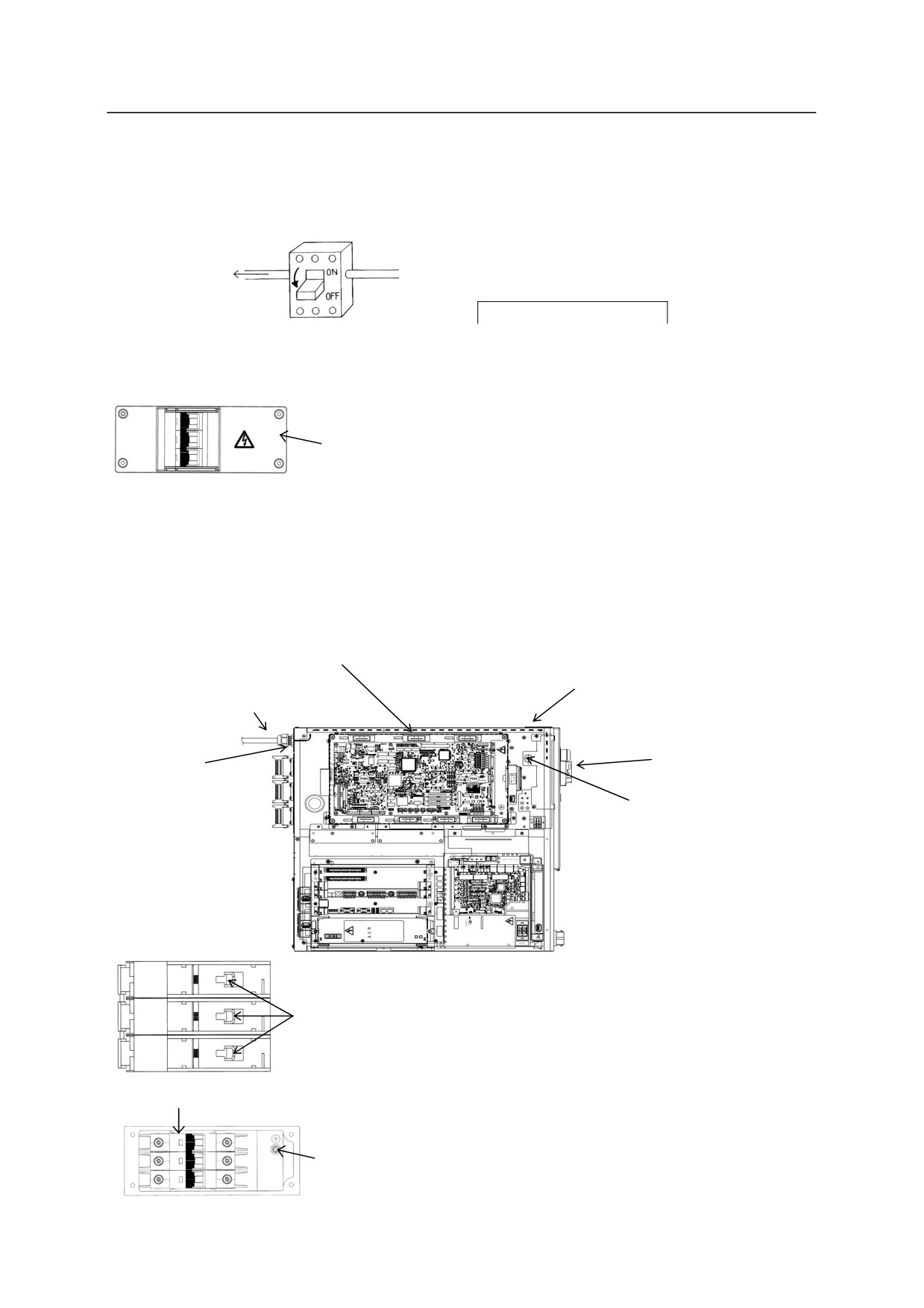
6. Connection
With transformer unit
1. Connection between the controller and the transformer unit
Connect the controller and the transformer unit with
dedicated power cable according to the following
Connect with the
procedure.
external power
1.
Turn OFF the external power for the controller.
circuit breaker at
2.
Set
CONTROLLER POWER switch on the
the installation site.
controller to the OFF side without fail.
3.
Open the top plate and front cover of the controller,
OFF
and remove incoming plate on the rear side (upper,
without hole) and incoming plate on the side (with seal
Front cover
connector). On this occasion, mount the above
incoming plate on the rear side to the inlet on the side.
*The incoming plate on the side with seal connector is
not used.
4.
Insert the power cable from the inlet on the rear side,
and wire it to the breaker through the wiring route
shown in the figure below.
(At this time, tighten the
Wiring route inside controller
seal connector on the rear side securely.)
*Insert wire medial to the harness guide.
Use seal connector + incoming
Mount incoming plate on
plate mounted on power cable.
rear side (without hole)
to the inlet on the side.
Incoming
Breaker
plate on rear
side (upper)
XTRFAN
connector
Right side of breaker
5.
“XTRFAN” connector is provided at the place shown
above. Remove the jumper connector which is being
Connect here.
connected, and connect the connector of the power
cable.
(The removed jumper connector is not used.)
6. Connect the power cable to the place shown in the
Breaker
figure of the right side of breaker and the ground wire to
the place shown in the left figure.
Ground
7. Close the top plate and the front cover.
wire
connecting
6-16
screw
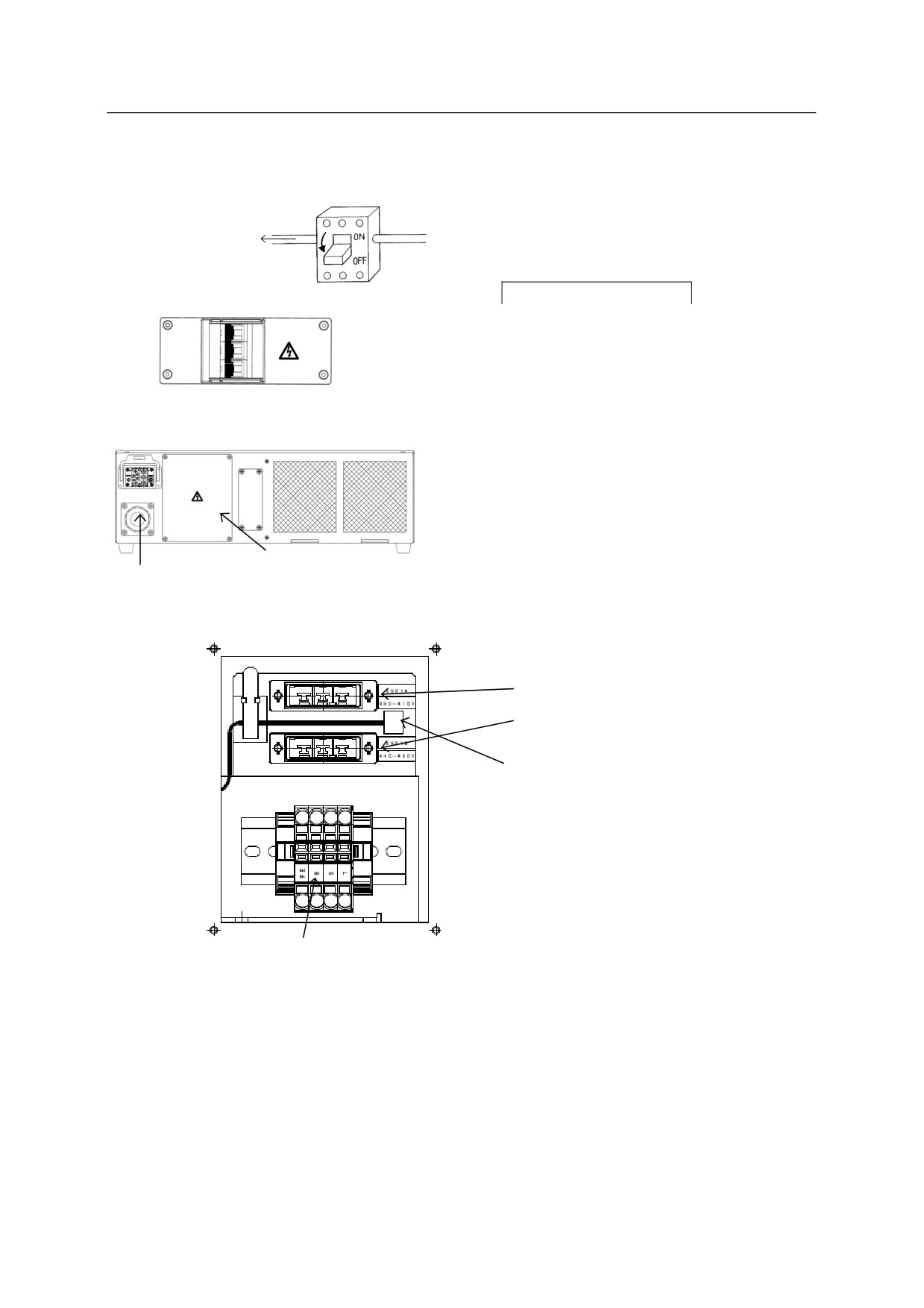
6. Connection
2. Connection between external power and transformer unit
Connect the external power with the transformer
Connect with the
unit according to the following procedure.
external power
1. Turn OFF the external power for the control
circuit breaker at
the installation site.
equipment.
2. Set
CONTROLLER POWER switch on the
OFF
transformer unit to the OFF side without fail.
3. Feed the external power cable into the inlet
on the rear side of transformer unit.
4. Open the power connection/setting plate, and
Rear
connect X601 power source connector in
accordance with the voltage to be used.
5. Connect external power cable to each
terminal of PE, R, S and T of TB1 terminal
block.
Power connection/
External power inlet
Setting plate
Opened in the figure below.
(A)380V-415V connector
(B)440V-480V connector
Connect X601 power source connector
bound at the place to the above (A) or (B)
in accordance with the voltage to be used.
TB1 terminal block: PE, R, S and T from the left [Terminal block type: 2006-1201/WAGO]
(1) When using naked wire
Recommended wire diameter: AWG10-AWG8
(2) When using Ferrule with insulation collar
Recommended wire diameter: AWG10
Connecting terminal length: 12 mm
*Refer to the specifications of terminal block manufacturer for details.
6-17
6. Connection
y Seal connector for external power inlet is provided on the rear side of transformer unit.
Use the power cable whose diameter is 16-22.
Lock nut
Cable
Transformer unit cabinet
y The stripped length of cable sheath of inserted power cable should be 150 mm or less.
150 mm or less
NOTE*: If the cable diameter is more than 22, prepare a seal connector which is appropriate
for the cable diameter. The hole diameter of the plate for transformer unit inlet is
34.
!
CAUTION
1. Confirm current requirements and select a power cable with
adequate capacity.
2. Do not install wire that is too small in diameter, the voltage may
drop or the cable may overheat.
3. Confirm that two fans of the transformer unit rotate properly
after connecting the transformer unit and the controller with
their power switch ON.
6-18
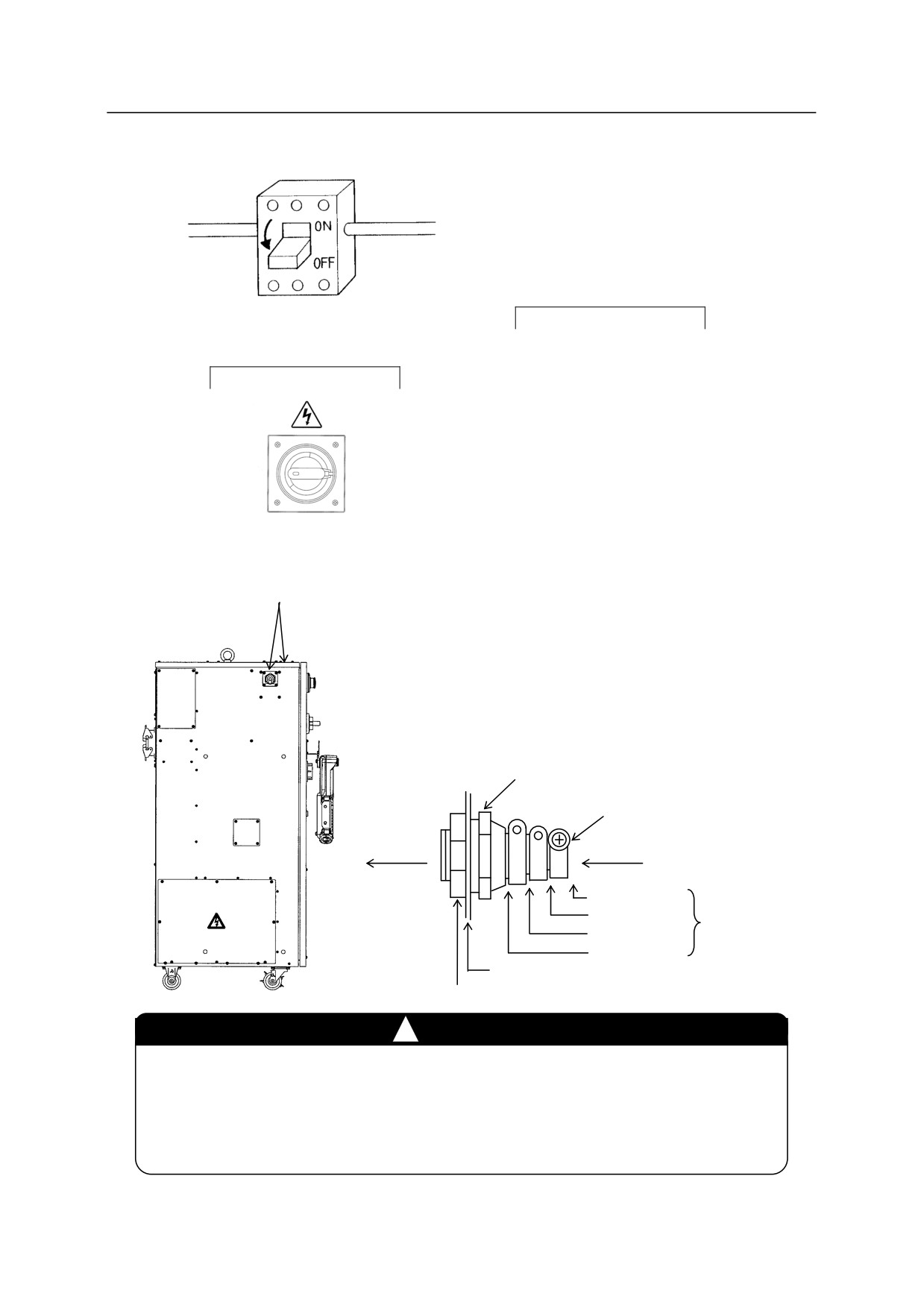
6. Connection
E4x controller
Connect the external power according to the
following procedure.
1. Turn OFF the external power for the
controller.
Connect with the external power circuit
2. Set
CONTROLLER POWER switch on the
breaker at the installation site.
controller door to the OFF side.
CONTROLLER POWER Switch
3. Feed the external power cable into the inlet
on the left side of controller.
Detailed procedure of fixing a cable is shown below.
y Cut a cable gland (supplied with the controller) in
accordance with the diameter of the cable.
NOTE*: If the cable diameter is more than 19,
prepare a seal connector which is
External power inlet
appropriate for the cable diameter.
The hole diameter of the plate is 34.
y Pass the cable through the cable gland.
y Tighten the screw after adjusting length of the
cable.
y Pass the cable through the inlet and tighten the lock
nut.
Cable gland
䡚
Inside
Outside
Tightening screw
Cable
9 - 12
Cutting position
11 - 14
䡚
14 - 17
(xx: diameter of cable)
17 - 19
Controller enclosure
Lock nut
!
CAUTION
1. Confirm current requirements and select a power cable with adequate
capacity.
2. Do not install wire that is too small in diameter, the voltage may drop or the
cable may overheat.
6-19
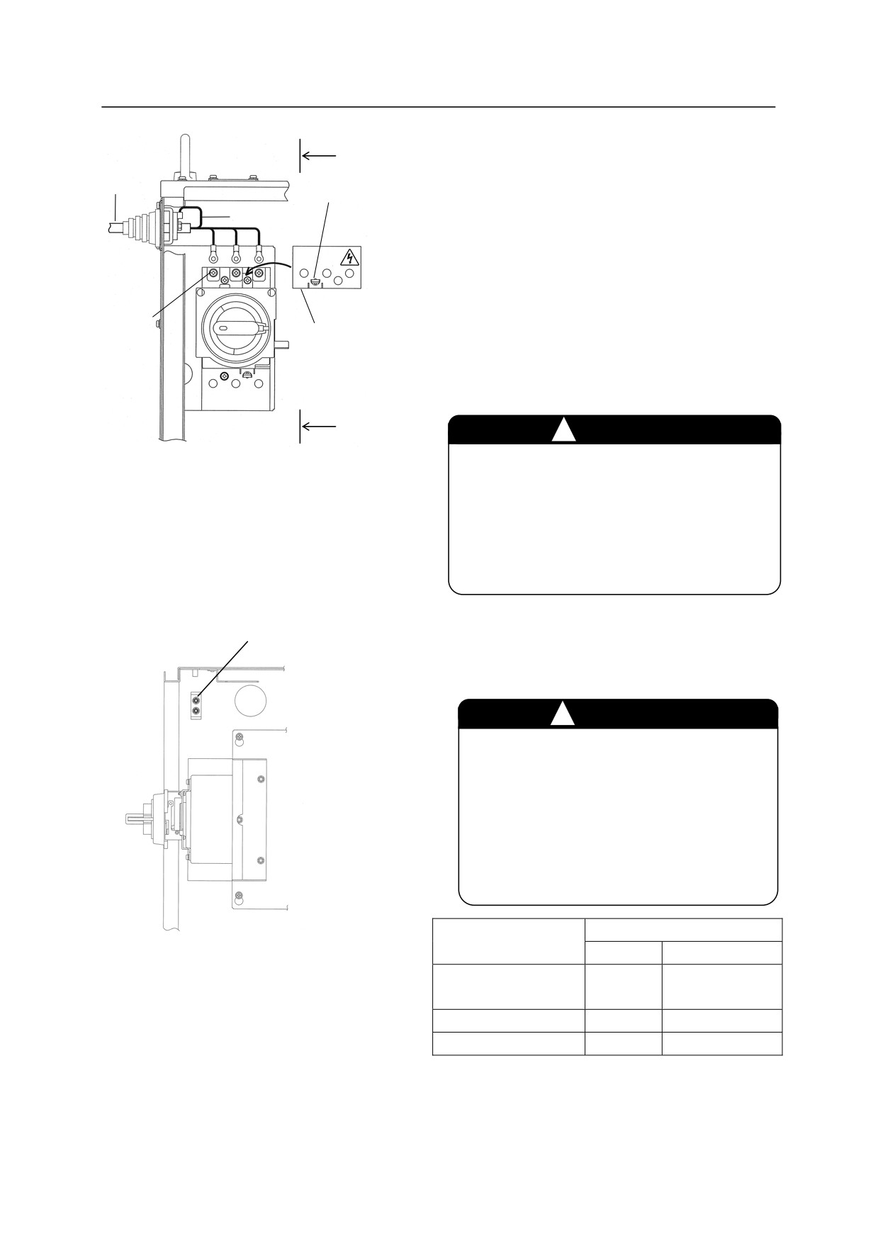
6. Connection
External
A
4. Attach round, crimp-type terminals on the
power
ends of the individual wires of the power
cable
Lock detent
cable. Use round insulators on each of these
Earth wire
wires to prevent contact between the crimped
part and metal.
(See left figure.)
5. Connect the external power cable to the
Breaker
breaker terminal (3 screws), and the dedicated
screw
External power cable
connection terminal
earth terminal.
cover
A
WARNING
!
Tighten the terminal screws securely.
Connect the earth wire to the earth terminal
Operating the robot with loose terminals
as shown below.
is very dangerous and may lead to electric
shock, robot malfunction, or breakdown
of the electrical system.
E4x controller
Earth terminal
6. Mount the external power cable connection
terminal cover.
!
DANGER
Mount the external power cable
connection terminal cover when the
wiring is complete. Failing to mount
the cover may lead to electric shock
due to accidental contact with power
line.
View A-A
Electric cable size
Crimp-type terminal size
to be used
Breaker
Earth terminal
3.5 mm2 (AWG12)
R5.5-5
R5.5-5
5.5 mm2 (AWG10)
8 mm2 (AWG8)
R8-5
R8-5
13 mm2 (AWG6)
R14-5
R14-5
6-20