Kawasaki Robot (B, BA, CP, CX, M, MC, MS, R, Y, Z). Instruction Manual (2015) - page 5
4. Transportation
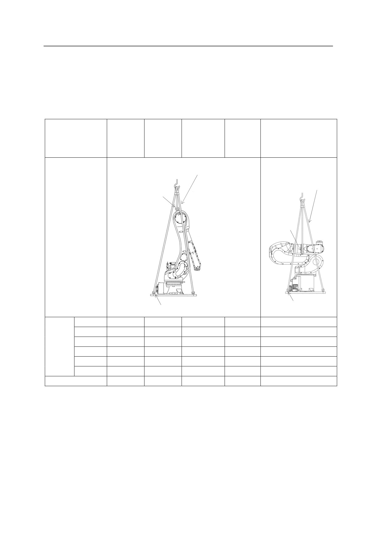
Using Wire Sling (With base plate)
According to the figure below, hoist up the robot by fastening four wire slings to four eyebolts on
the base plate. In addition, fasten a wire sling to the eyebolt on the arm to prevent the robot
from accidentally falling. (Use the same method for hoisting up the robot with pedestal.)
RA06L
RA10L
RD80N
RA10N
RA20N
RS30N
Model
RS15X
RC05L, RS05L, RS05N
RS06L
RS10L
RS50N
RS10N
RS20N
RS80N
5 Wires
6 Wires
1 Eyebolt
2 Eyebolts
Hoisted
up
posture
4 Eyebolts
4 Eyebolts
JT1
0°
0°
0°
0°
0°
JT2
0°
-3°
0°
1°
-80°
Hoisted
JT3
-163°
-163°
-155°(-55°)
-155°
-170°
up
JT4
0°
0°
0°
0°
0°
posture
JT5
-17°
-20°
-25° (0°)
-114°
90°
JT6
0°
0°
0°
0°
0°
Eyebolts for arm
M16×1
M16×1
M24×1
M24×1
M8×2
(
): RD80N
4-36
4. Transportation
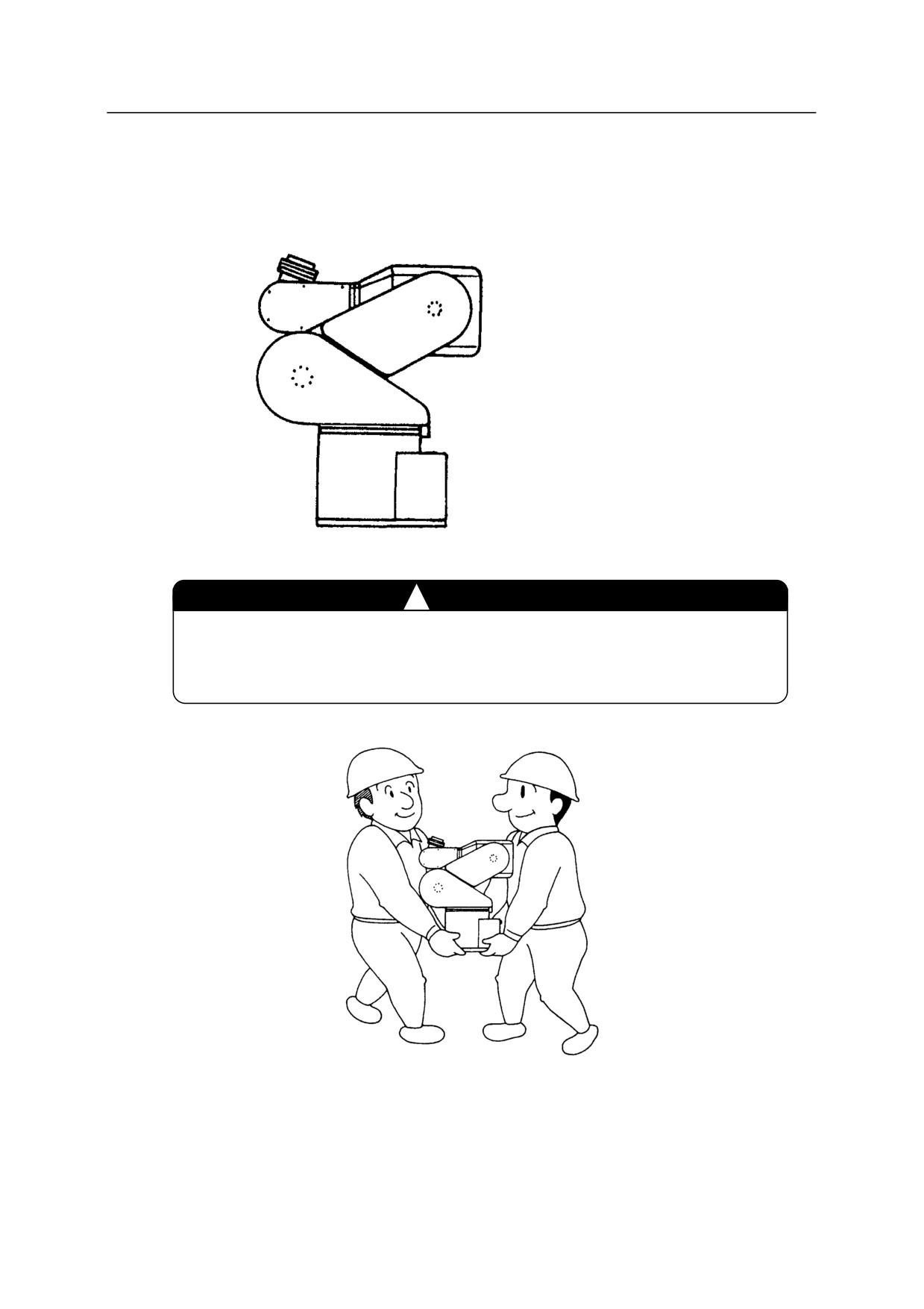
By Two Or More Persons
Robot arm is packed as shown below at time of factory shipment.
Standard posture
JT1 :㻌 0
JT2 :㻌 -60
JT3 :㻌 -150
JT4 :㻌 0
JT5 :㻌 +135
JT6 :㻌 0
RS03N
!
CAUTION
The mass of robot arm is approx. 20 kg for model RS03N. For your
safety, transport robot arm by two or more persons.
4-37
4. Transportation
4.3.8 YF SERIES
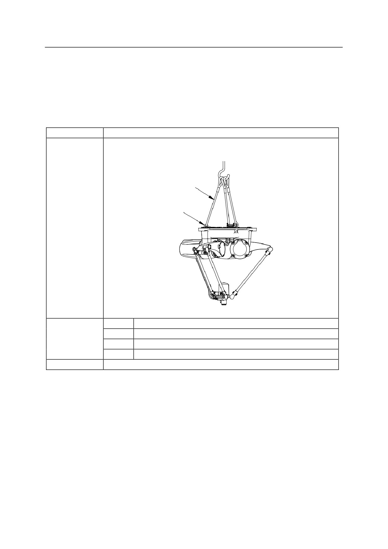
Using Wire Sling
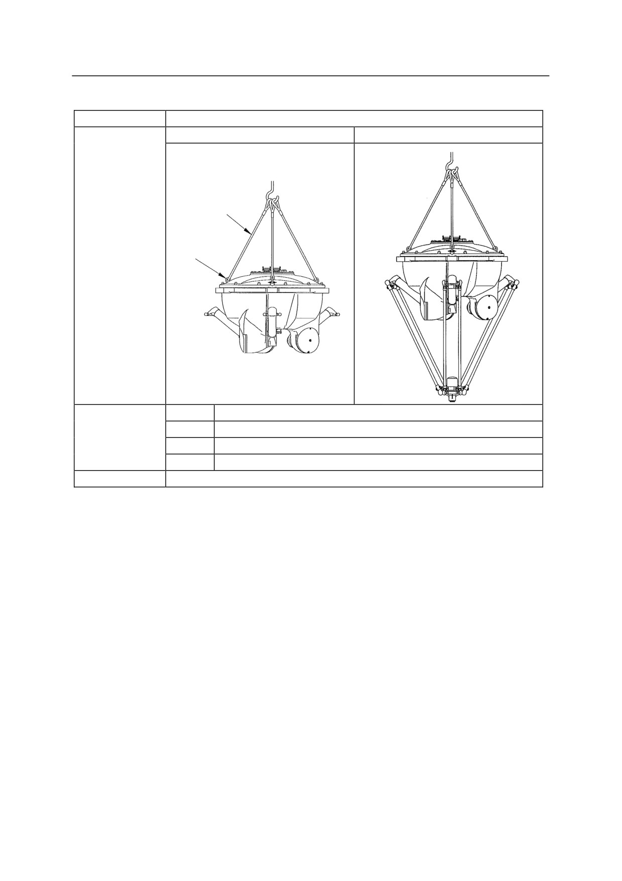
According to the figure, attach three eyebolts to arm and hoist up by attaching wire slings to the
jigs.
Model
YF002N
3 Wires
3 Eyebolts
Hoisted
up
posture
JT1
0°
Hoisted
JT2
0°
up
JT3
0°
posture
JT4
0°
Hoisting jig
0EBM8Z (Eyebolt)×3
4-38
4. Transportation
Model
YF003N
At time of shipment
After assembly of lower arm
3 Wires
3 Eyebolts
Hoisted
up
posture
JT1
-28°
Hoisted
JT2
-28°
up
JT3
-28°
posture
JT4
0°
Hoisting jig
60154-1879 (Eyebolt)×3
4-39
4. Transportation
4.3.9 ZB SERIES
Using Wire Sling
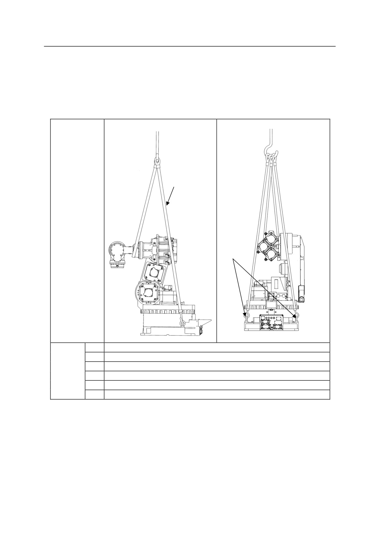
According to the figure, hoist up the robot by three slings through two eyebolts.
3 Wires
Hoisted up
posture
Eyebolts
JT1
0
JT2
-15
Hoisted
JT3
-15
up
JT4
0
posture
JT5
-90
JT6
0
4-40
4. Transportation
Using Forklift
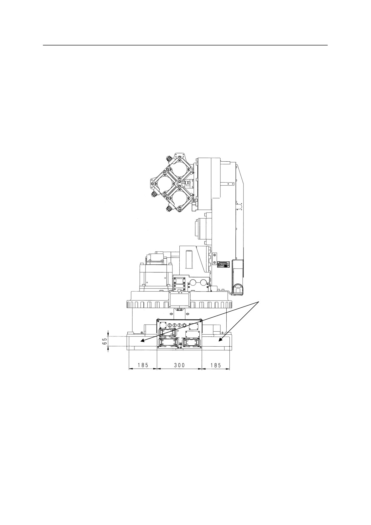
1. When carrying by forklift, use the pocket for the forklift located at the robot base.
2. Before carrying robot by forklift, set JT2 to approx. -15, and JT3 in a horizontal position.
3. Confirm that the forks of forklift penetrate sufficiently without fail.
4. When transporting robot on an inclined or rough surface, be careful to maintain balance to
prevent forklift/robot from falling.
Fork pocket
4-41
4. Transportation
4.3.10 ZD/ZT/ZX SERIES
Using Wire Slings
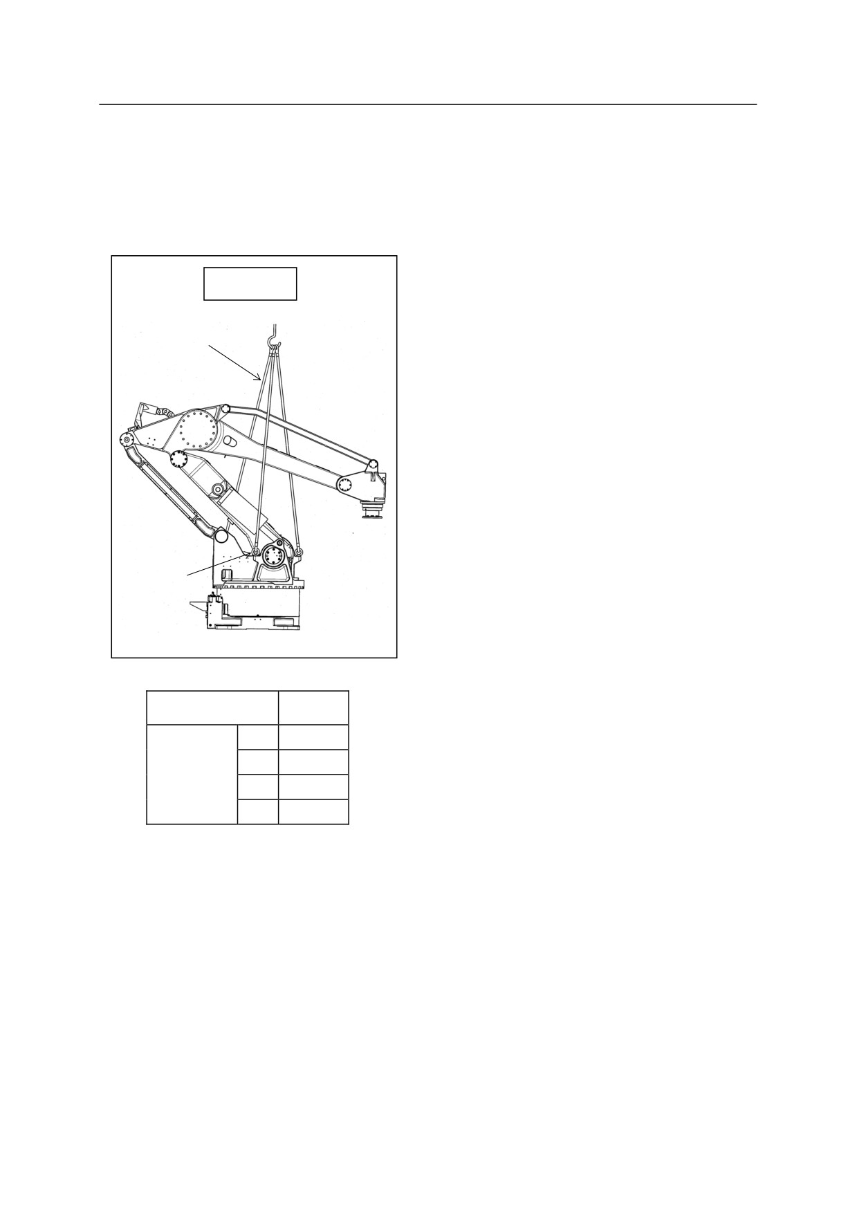
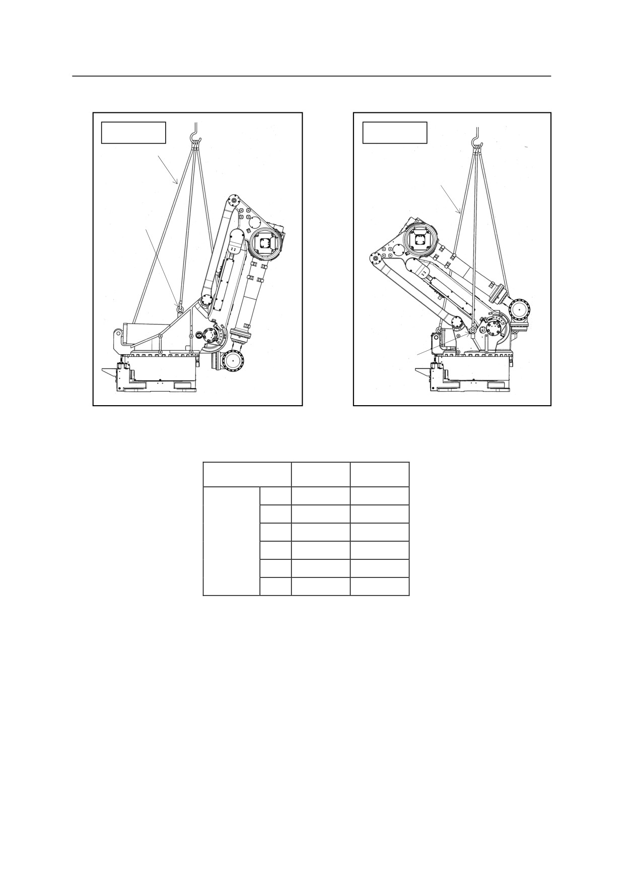
According to the figure, hoist up the robot by three wires through three eyebolts.
ZD Series
3 wires
Eyebolts
Model
ZD
JT1
0
Shipment
JT2
-45
posture
JT3
-20
JT4
0
4-42
4. Transportation
ZT series
ZX series
3 wires
3 wires
Eyebolts
Eyebolts
Model
ZT
ZX
JT1
0
0
JT2
-70
-52
Hoisted
JT3
-13
-35
up
JT4
0
0
posture
JT5
-103
-55
JT6
0
0
4-43
4. Transportation
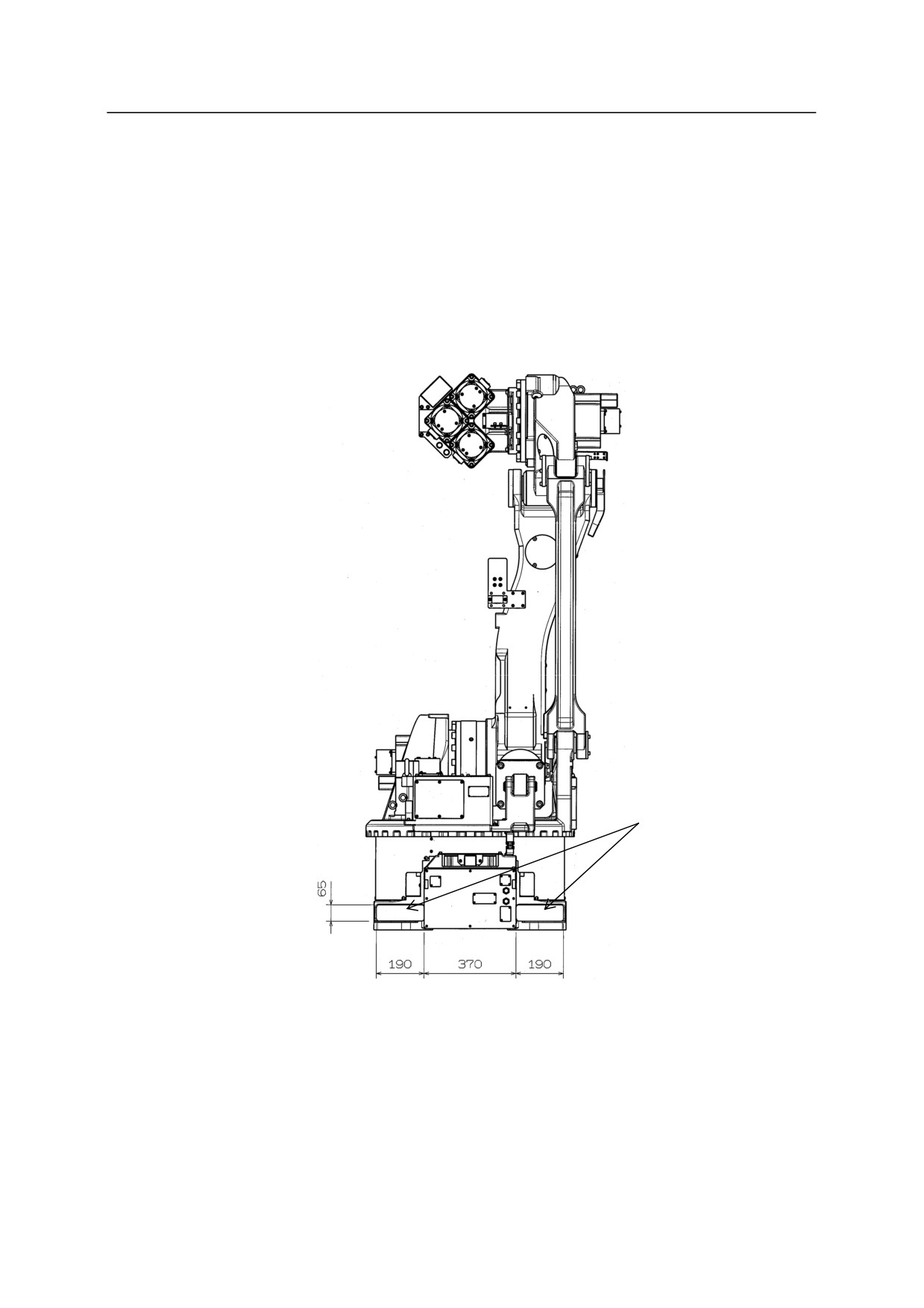
Using Forklift
1. When carrying by forklift, use the pocket for the forklift located at the robot base.
2. Confirm that the forks of forklift penetrate sufficiently without fail.
3. When transporting robot on an inclined or rough surface, be careful to maintain balance to
prevent forklift/robot from falling.
4. When the retract stopper and retract pin (Option) are mounted, set the forks of forklift to a
height of 54 mm or less.
Fork pocket
4-44
4. Transportation
4.3.11 ZH SERIES
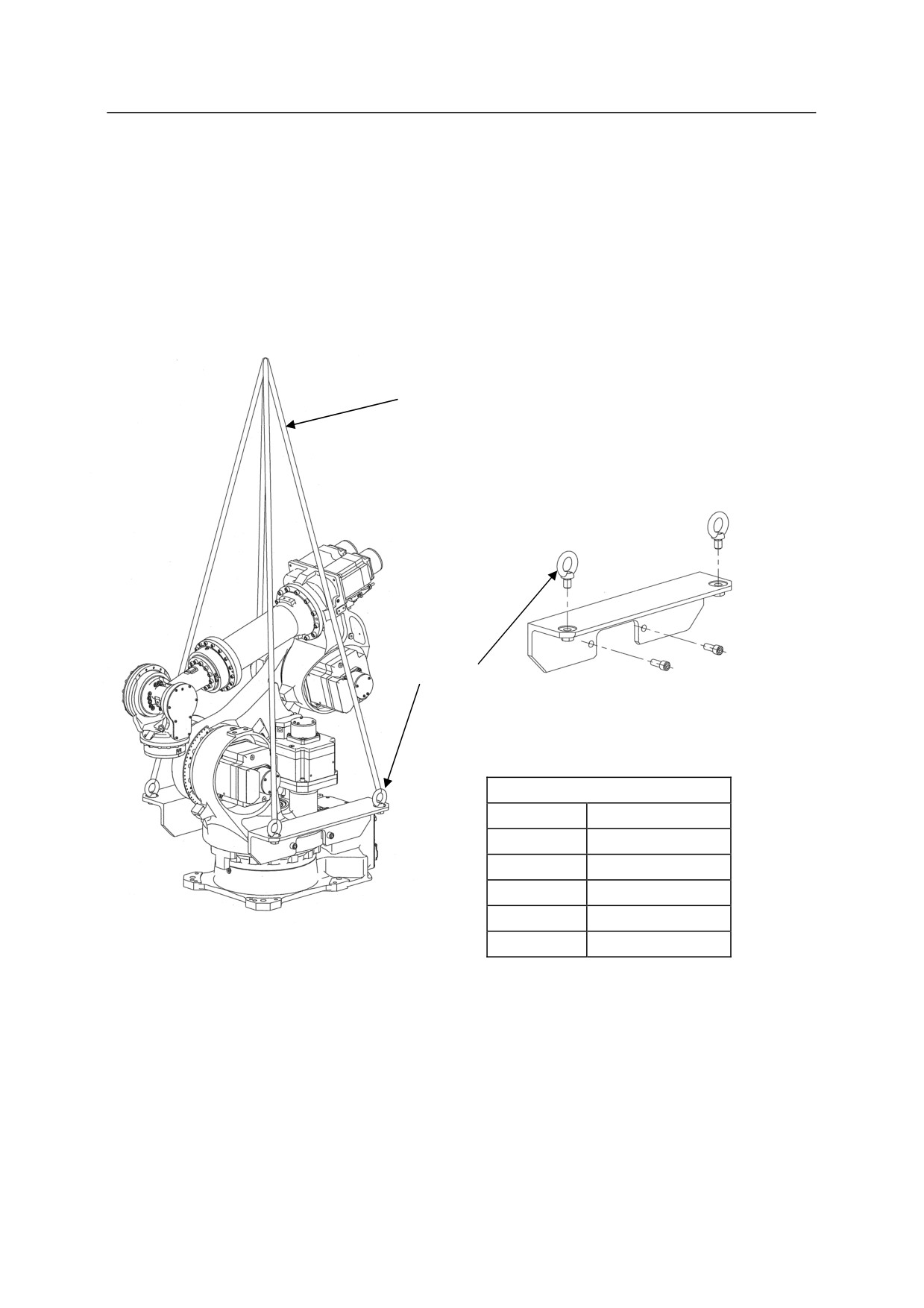
Wire Sling
According to the figure, mount a hoisting jig and eyebolts. Hoist up the robot by four slings
through four eyebolts.
4 Wires
Eyebolts
Hoisting jig
Hoisted up posture
JT1
0
JT2
-60
JT3
-15
JT4
0
JT5
-17
JT6
0
4-45
4. Transportation
4-46
5. Installation
5.0 INSTALLATION
5.1 INSTALLATION ENVIRONMENT
The installation site of the robot must fulfill all the following environmental conditions:
1.
When robot arm is installed on the floor, the levelness must be within 5.
2.
Be sure that the floor/stand has sufficient rigidity.
3.
Secure a flat place to prevent the base section from receiving undue force.
(If an accurate flatness is unobtainable, insert liners and adjust the flatness).
4.
Keep the ambient temperature during operation within the range of 0C to 45C (with the
exception of E70/E71 controllers installed on the side and E91 controller: 0C to 40C).
Deviation or overload error may occur due to high viscosity of grease/oil when starting
operation at low temperatures. In this case, warm-up robot at low speed before regular
operation.
5.
Keep the relative humidity during operation within the range of 35% to 85%RH without dew
condensation.
6.
The altitude of the installation place should be within the range of 0 m to 1000 m above
mean sea level.
7.
The robot installing place should be free from dust, dirt, smoke, water, and other foreign
matters.
(In dusty or moist condition, use a robot arm with dust-proof or waterproof spec.)
8.
The robot installing place should be free from flammable or corrosive liquid or gas. (Use an
explosion-proof arm in a flammable environment.)
9.
The robot installing place should be free from excessively strong vibration. (0.5 G or less)
10.
The robot installing place should be free from electric noise interference.
11.
Place where power satisfying the specification is supplied.
12.
Place where dedicated earthing is provided. (100 or less)
13.
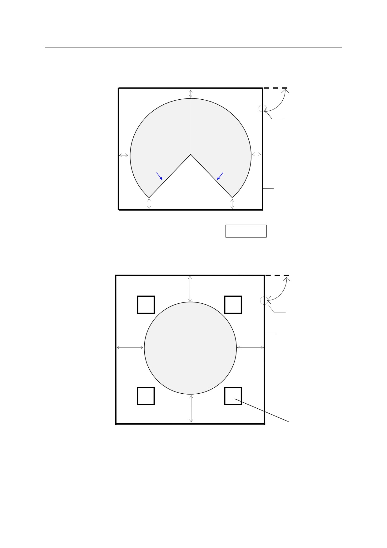
The robot installing place should be sufficiently larger than the motion range of robot arm.
Safety fence must enclose area larger than the maximum motion range of fully equipped
robot arm (with tools) so it does not interfere with the surrounding objects.
(1) Enough space for easy access to the controller during maintenance.
(2) An entrance gate with a safety plug should be provided to the safety fence.
(3) About details of the safety fence, observe the requirements which are established in each
region. (e.g. EN953, EN294, EN811, EN1088, ISO13852, ISO13854, and ISO/NP
14120)
5-1
5. Installation
Approx.1 m
Gate with safety plug
Motion range of robot arm
(tool/workpiece included)
Approx.1 m
Approx.1 m
Mechanical
Mechanical
stopper
stopper
Safety fence
Approx.1 m
Approx.1 m
Controller
YF Series
Approx. 1 m
Gate with safety plug
Safety Fence
Motion range of robot arm
Approx.1 m
Approx.1 m
(Tool included)
Approx. 1 m
Column
5-2
5. Installation
5.2 SAFETY MEASURES CONCERNING ROBOT INSTALLATION
(1) Always place the robot arm within the safeguarding devices (guard, fence, equipment, etc.
provided for preventing hazards) so that the robot arm is put off limits. Also, install an
emergency stop device in an easily accessible area within reach of the operator.
(2) Safety guarding zone (area surrounded by the safety fence) should be built so as to prevent the
robot arm from jumping over or extending beyond the fence in the event of breakdown and/or
error.
(3) Minimize the number of doors on the safeguarding devices (preferably only one). The door
should be equipped with a safety plug which must be removed manually in order to
open/close the door. Then, set motor power to be turned OFF if plug is removed during
automatic operation. Confirm that safety devices such as EMERGENCY STOP switch and
safety plug function normally before entering the safeguarding devices. Then, the operator
must set TEACH LOCK switch on the teach pendant to ON to prevent personnel from
accidentally switching to automatic mode. Also, the operator must keep the plug on
him/herself.
(4) Display the robot state clearly, such as: automatic mode, teaching, and emergency stop, etc. on
the safeguarding devices so the current condition of the robot can be seen by everybody.
(5) Limit the robot operating personnel to only those who have taken and completed the training
course(s) authorized by Kawasaki.
5-3
5. Installation
5.3 METHODS OF INSTALLATION
5.3.1 INSTALLING ROBOT CONTROLLER
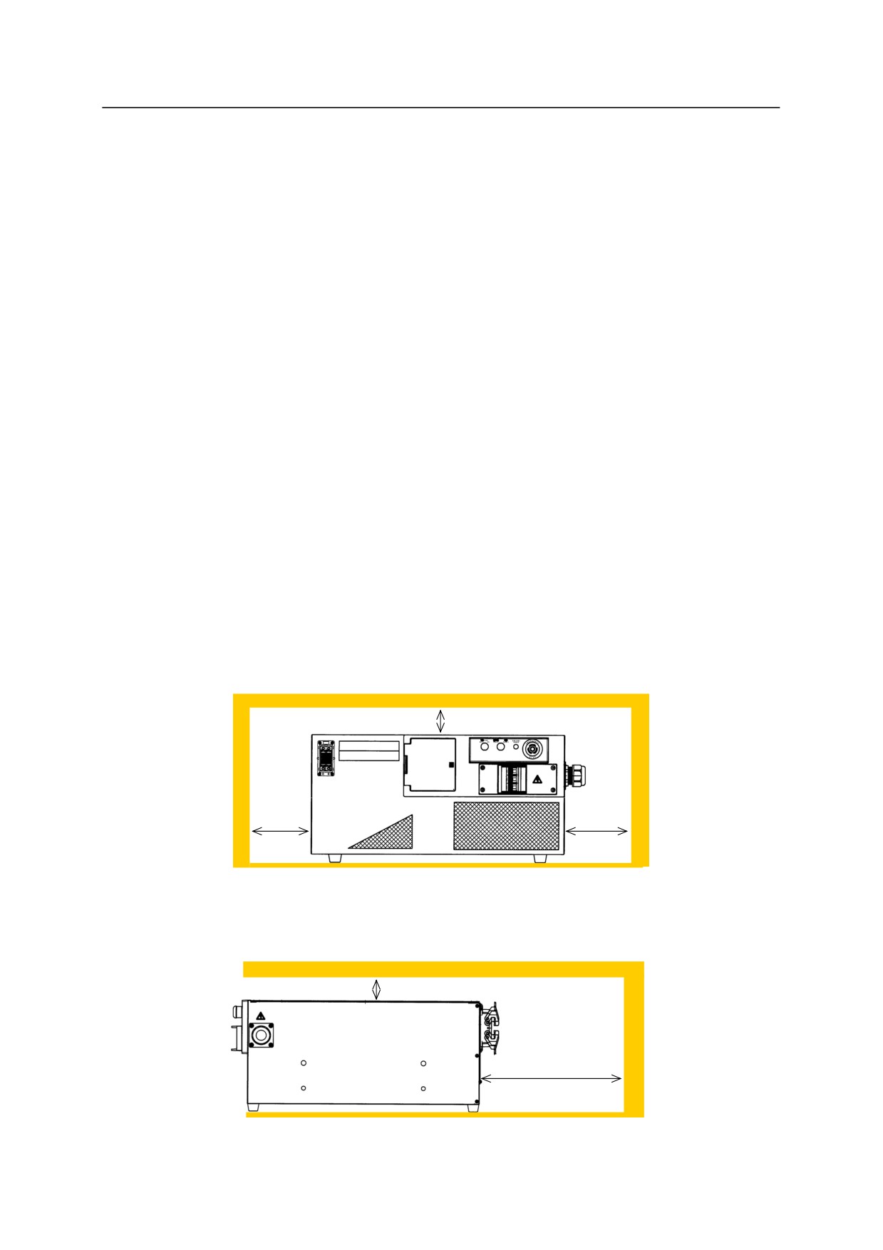
In order for the controller to maintain the proper internal temperature, the installation site must
conform to the points below.
5.3.1.1 INSTALLING E0X CONTROLLERS
When an object is placed on the top surface of the controller, the mass should be 45 kg or less.
It is possible to place a controller on another controller as far as the mass goes. However, when
an object is placed on the top surface of the controller, it is necessary to remove the object once in
maintenance.
1. Arrange the controller on a flat, horizontal stand and adjust its height so that the heights of
controller power switch and operation switches from the floor are between 0.6 to 1.9 m.
(Provide a clearance of rubber feet height in the vertical direction because there is an air inlet
on the bottom.)
2. Separate the controller right/left side from the wall by 100 mm or more.
3. Separate the controller top surface from the wall by 20 mm or more.
20 mm or more
100 mm
100 mm
or more
or more
20 mm or more
200 mm or more
5-4
5. Installation
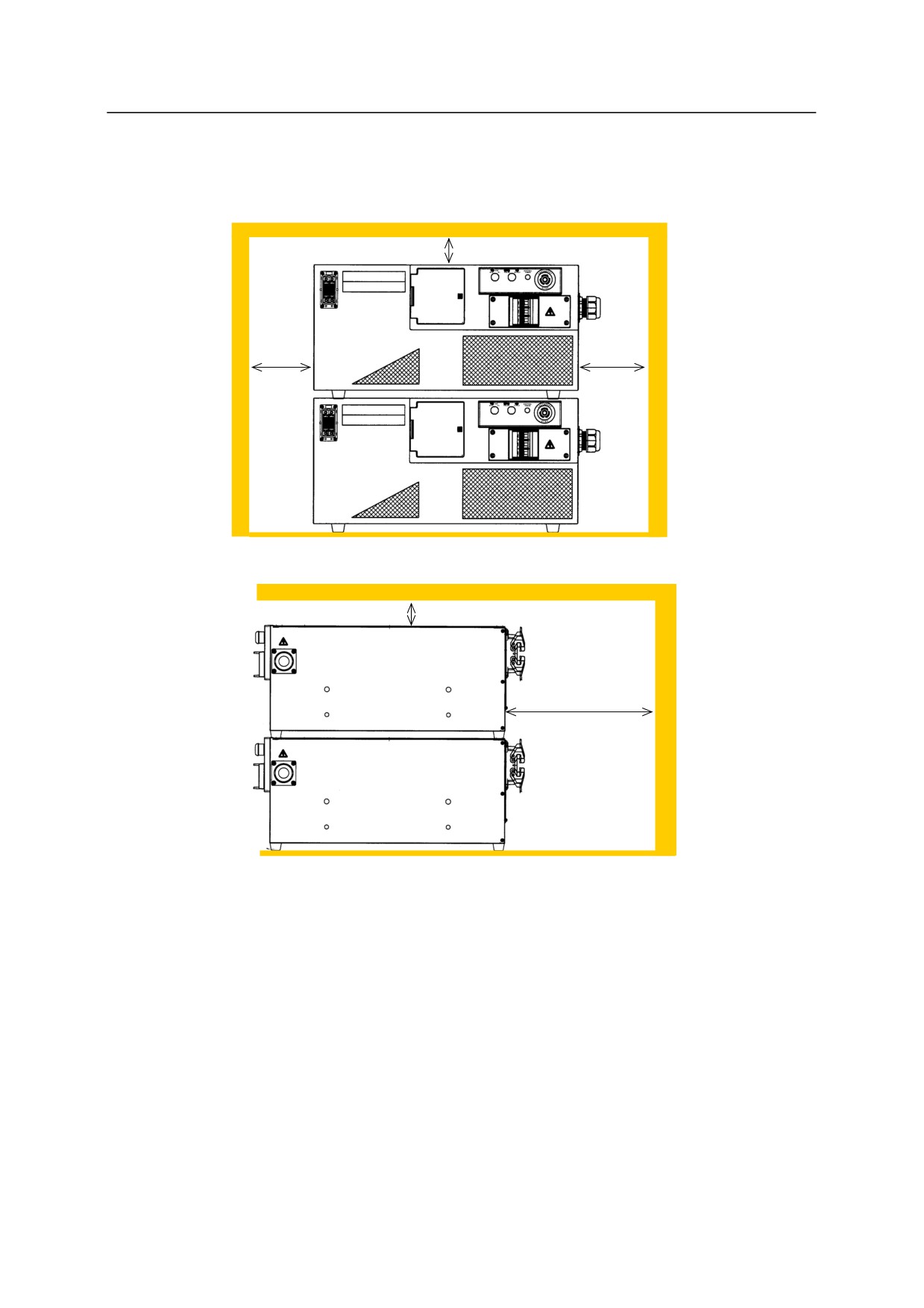
For horizontal arrangement, a controller can be placed on another controller.
20 mm or more
100 mm
100 mm
or more
or more
20 mm or more
200 mm or more
5-5
5. Installation
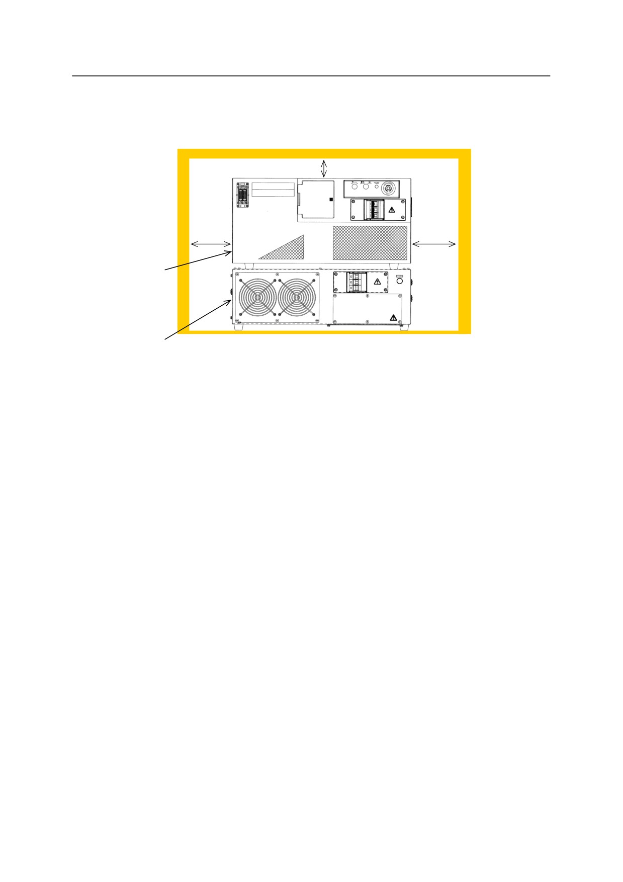
It is also possible to place a controller on a transformer unit for horizontal arrangement.
20 mmor more
100 mm
100 mm
or more
or more
Controller
Transformer
unit
5-6
5. Installation
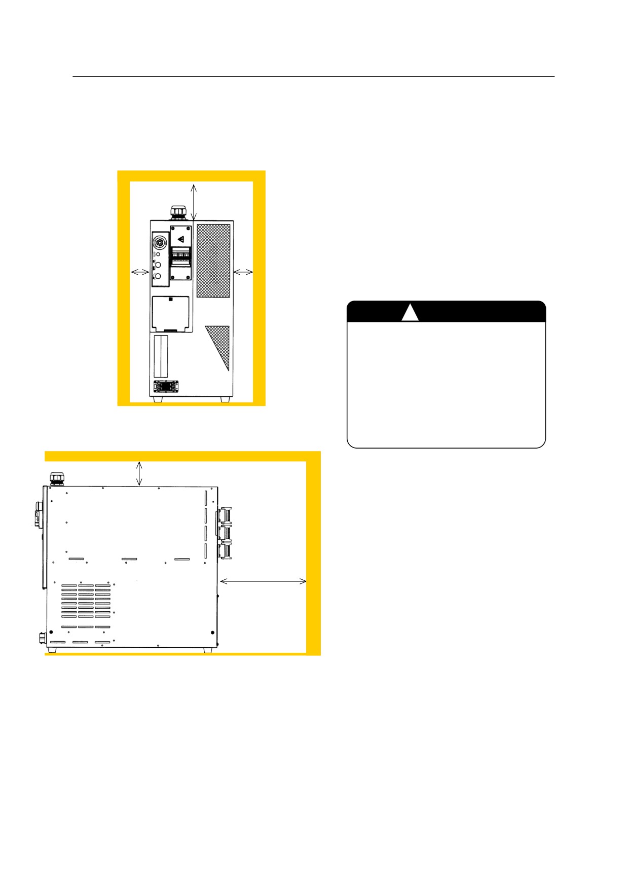
Follow the procedure below when arranging the E0x controllers vertically. Feet attached on the
bottom of the controller can be reattached on the left side. An object cannot be placed on the top
surface of the controller when the controllers are placed vertically.
1. Arrange the controller on a horizontal
100 mm
stand and adjust its height so that the
or more
heights of controller power switch and
operation switches from the floor are
between 0.6 to 1.9 m. Arrange the
20 mm
20 mm
controller with its controller power
or more
or more
switch facing upward.
㸟
CAUTION
When arranging the controller
vertically, the exhaust port comes
bottom. Accordingly, reattach
the rubber feet without fail ,and
provide a clearance between the
floor and the bottom.
100 mm or more
2. Separate the controller right/left side
from the wall by 20 mm or more.
3. Separate the controller top surface from
the ceiling by 100 mm or more.
4. Separate the controller rear side from the
wall by 200 mm or more.
200 mm or more
5-7
5. Installation
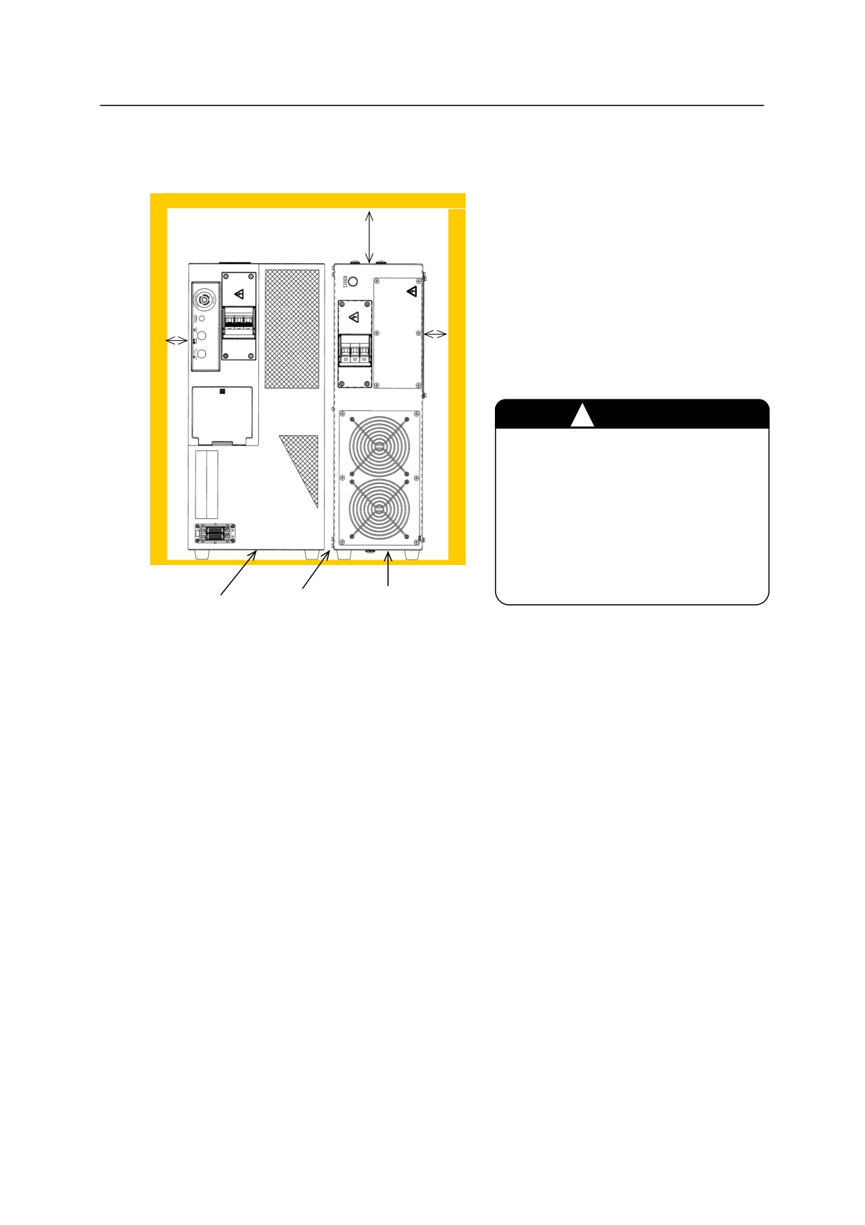
See the figure below when arranging the transformer unit vertically.
100 mm
or more
20 mm
20 mm
or more
or more
㸟
CAUTION
Attach rubber feet on the bottom
surface when arranging the
transformer unit vertically.
Also, fix the transformer unit to
prevent it from falling because it
is small in width.
18 mm Transformer unit
Controller
or more
5-8
5. Installation
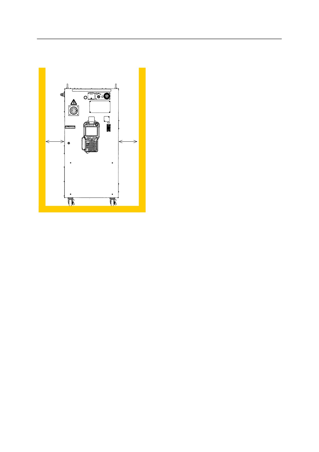
5.3.1.2 INSTALLING E4X CONTROLLERS
1. Arrange the controller on a flat,
horizontal floor. When an object is
placed on the top surface of the
controller, the mass should be 40 kg or
less.
2. Separate the controller right/left side from
100 mm
100 mm
or
or
the wall by 100 mm or more.
more
more
5-9
5. Installation
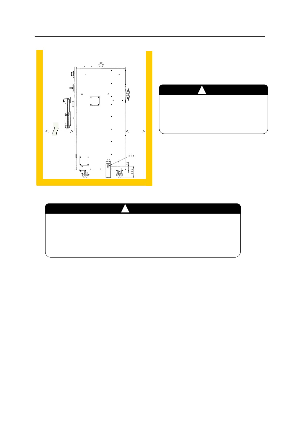
3. The inlet port for air-cooling is on the
rear upside of the controller, and the air
exhaust port is on the rear downside.
㸟
CAUTION
Do not block the air inlet and exhaust
ports when installing the controller.
Separate the controller backside from
the wall by 200 mm or more.
200 mm
1000 mm
or
or
more
more
4. Make fixing bracket(s), and fix the
controller with M12 bolts.
㸟
CAUTION
1. Release the stoppers on the two front casters of the controller when
moving the controller.
(Push the “OFF” side pedal.)
2. Relock the casters after the transport is complete.
(Push the “ON” side pedal for locking.)
5-10
5. Installation
5.3.1.3 INSTALLING E70/E71/E91 CONTROLLERS
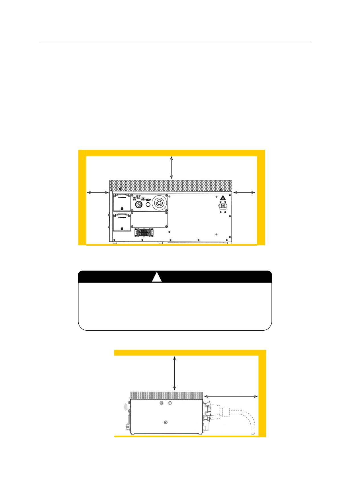
1. Arrange the controller on a flat, horizontal floor. An object cannot be placed on the top
surface of E70/E71 controllers. When an object is placed on the top surface of E91
controller, the mass should be 40 kg or less. It is possible to place an E91 controller on
another E91 controller as far as the mass goes. However, when an object is placed on the
top surface of E91 controller, it is necessary to remove the object once in maintenance.
2. Separate the controller right/left side from the wall by 100 mm or more.
3. Separate the controller top surface from the wall by 200 mm or more.
200 mm or more
100 mm
100 mm
or more
or more
4. Heat exchange fan is provided on the rear of E70/E71 controllers.
㸟
CAUTION
Do not block the air inlet and exhaust ports when installing the
E70/E71 controllers. Separate the controller rear side from
the wall by 300 mm or more for E70/E71 controllers and 200
mm or more for E91 controller.
200 mm or
E70/E71: 300 mm or
more
more
E91: 200 mm or more
5-11
5. Installation
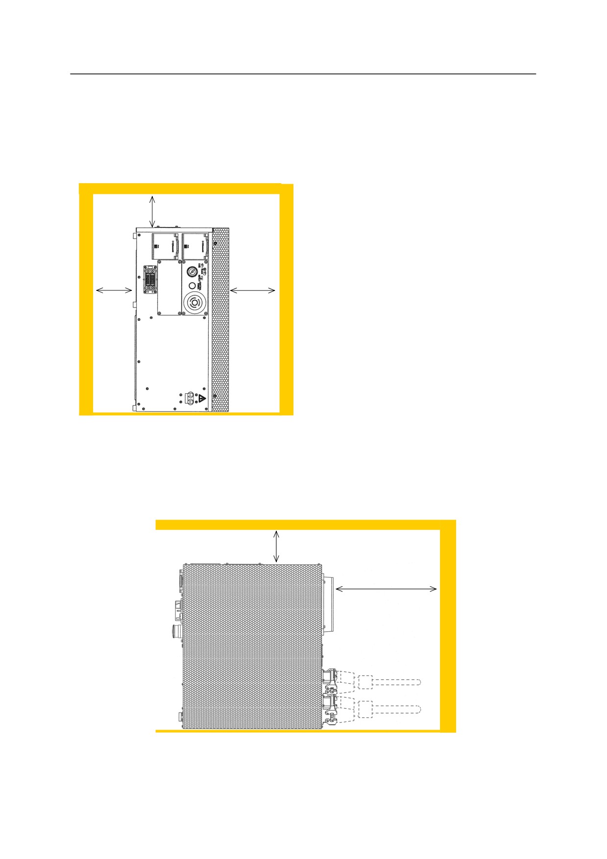
Follow the procedure below when arranging the E70/E71/E91 controllers vertically. The
ambient temperature should be within 0-40 C. For the E9x controller, feet attached on the
bottom of the controller can be reattached on the right side. An object cannot be placed on the
top surface of the controller when the controllers are placed vertically.
100 mm
1. Place the controller on a horizontal floor
or more
with its controller power switch facing
downward.
2. Separate the controller right side (or
ceiling surface when arranging the
100 mm
200 mm
controller vertically) from the wall by
or more
or more
200 mm or more.
3. Separate the controller top/left side from
the wall by 100 mm or more.
4. Separate the controller rear side from the
wall by 300 mm or more for E70/E71
controllers and 200 mm or more for E91
controller.
100 mm
or more
E70/E71: 300 mm or
more
E91: 200 mm or more
5-12
5. Installation
5.3.2 INSTALLING ROBOT ARM
5.3.2.1 INSTALLING B SERIES ARMS
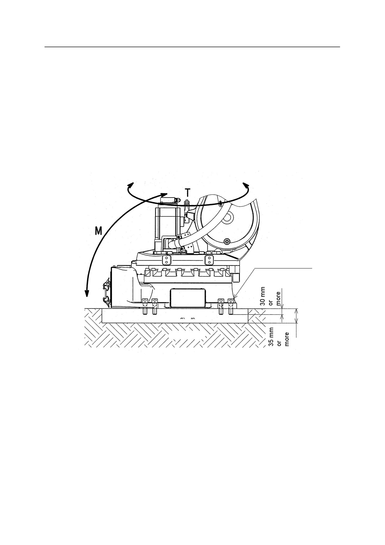
When Installing the Base Directly on the Floor
Bury a steel plate (35 mm Min. thick) in the concrete floor as shown in the figure below or fix it
with anchors. The steel plate must be fixed firmly so as to sustain reaction forces from the
robot.
M20
Tightening torque:
431 N·m
Steel plate
Concrete
5-13
5. Installation
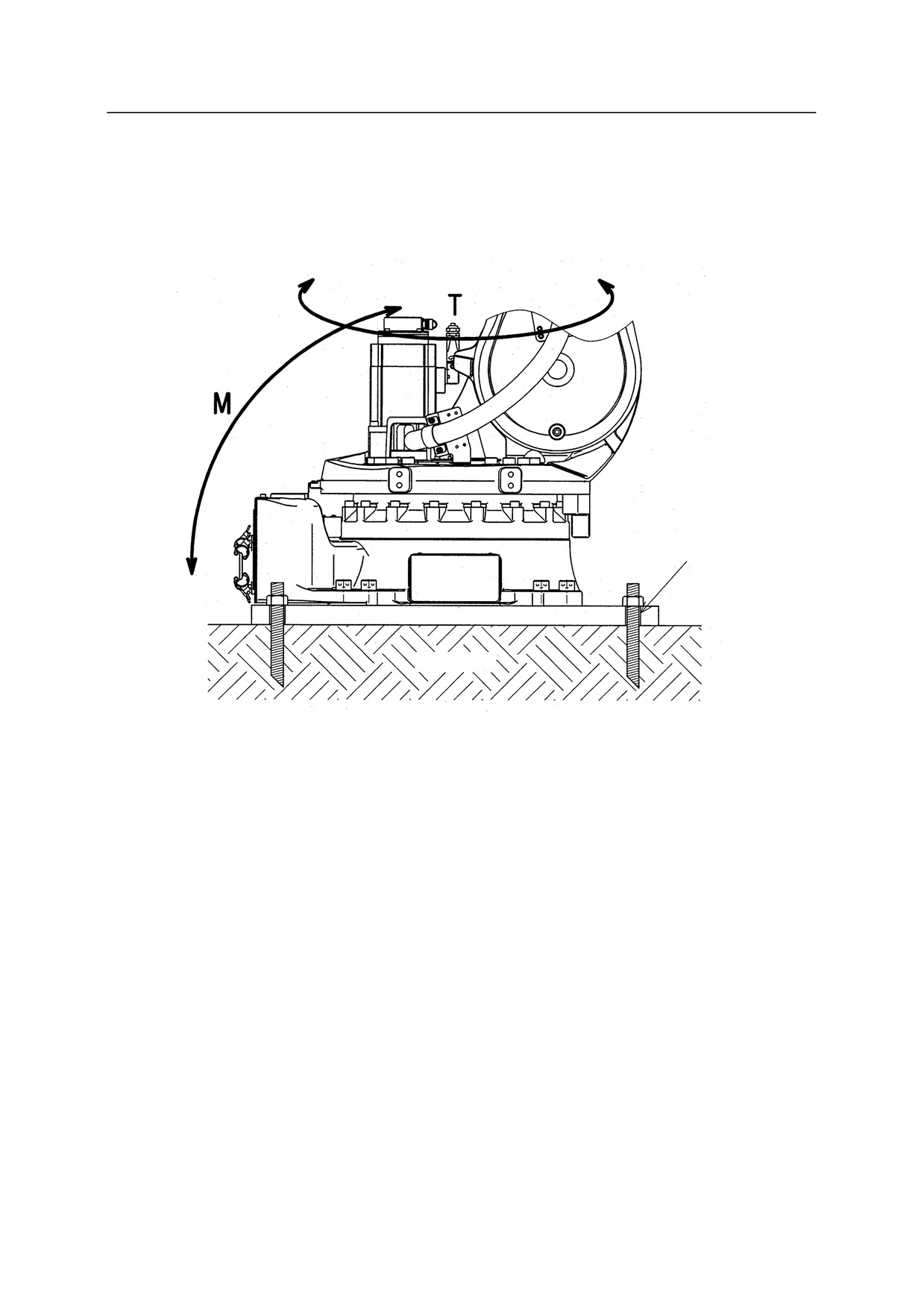
When Installing the Robot Base Plate on the Floor
In this case, install the base plate on concrete floor or steel plate using bolt holes on the base plate.
Reaction forces received from robot are the same as when installing the base directly on the floor.
Bolt hole
Base plate
Concrete
5-14
5. Installation
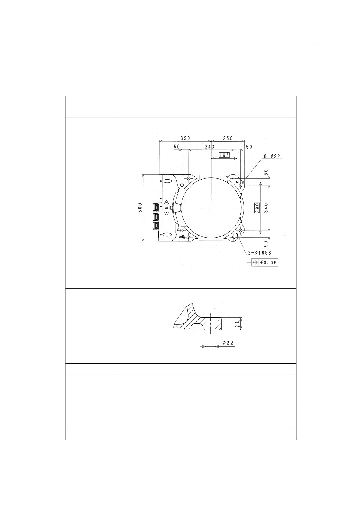
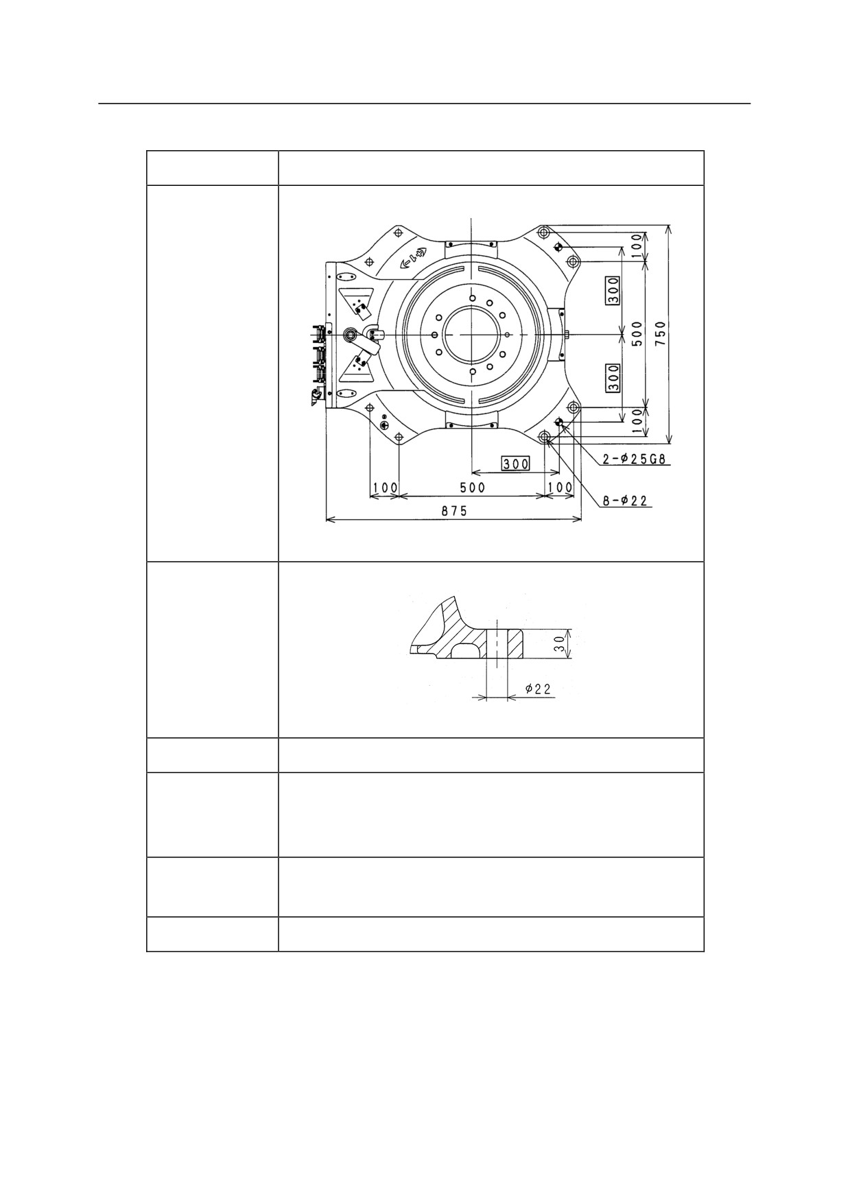
Installation Dimensions of Base Section
Fix the base section with high tension bolts through the bolt holes.
BT165L, BT200L, BX100L, BX100N,
Model
BX130X, BX165L, BX165N, BX200L
Dimensions for
installation
Cross-section
of installation
section
Bolt hole
8-22
8-M20
High tension
Material: SCM435
bolt
Strength class: 10.9 min.
Tightening
431 Nm
torque
Levelness
Within 5°
5-15
5. Installation
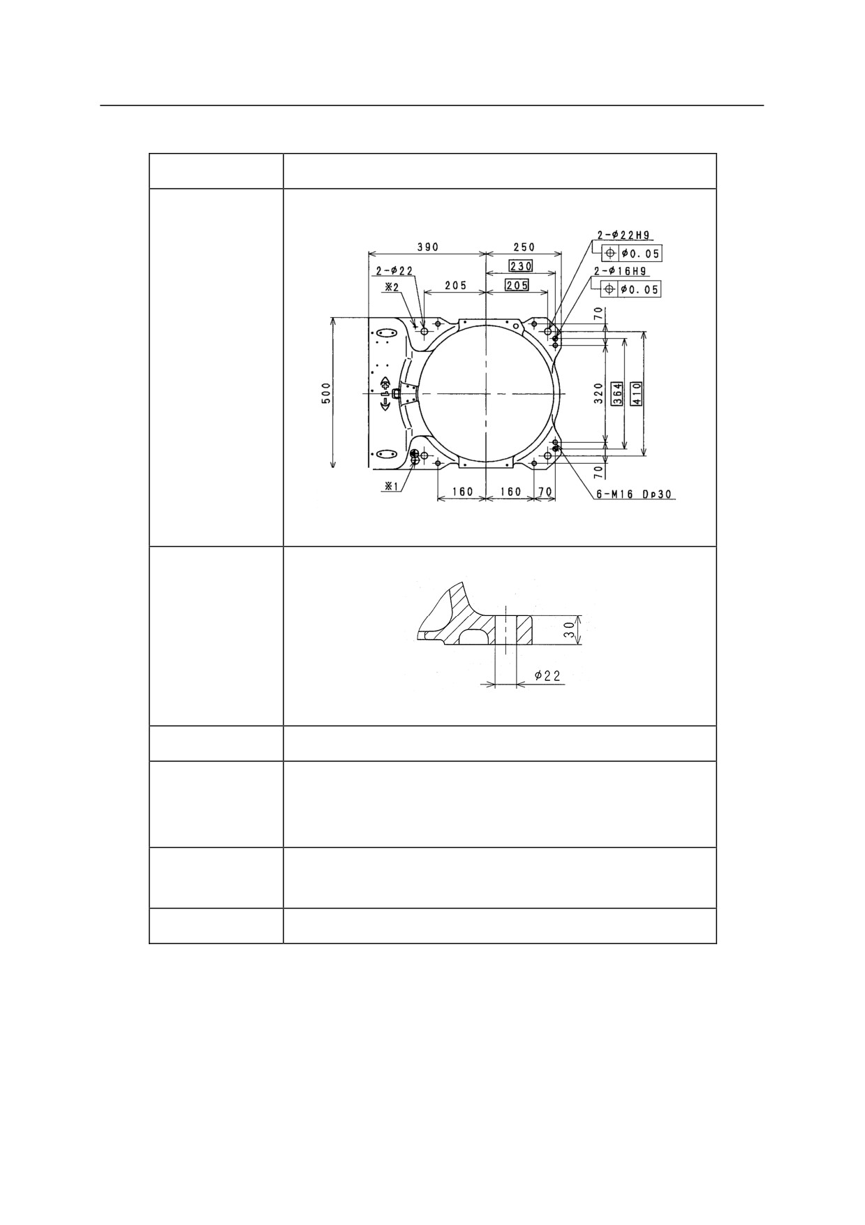
Model
BX100S
Dimensions for
installation
Cross-section
of installation
section
Bolt hole
4-22
4-M20
High tension
Material: SCM435
bolt
Strength class: 10.9 min.
Tightening
431 Nm
torque
Levelness
Within 5
Remove coating on the surface and mount ground line when using 䈜2 ground tap (M6)
without using 䈜1 ground tap (M6, 26 counterbore).
5-16
5. Installation
Model
BX250L, BX300L
Dimensions for
installation
Cross-section
of installation
section
Bolt hole
8-22
8-M20
High tension
Material: SCM435
bolt
Strength class: 10.9 min.
Tightening
431 Nm
torque
Levelness
Within 5
5-17
5. Installation
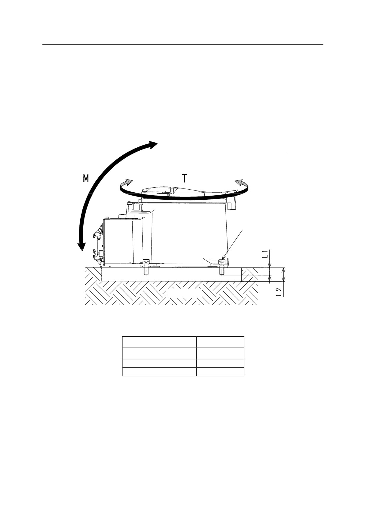
5.3.2.2 INSTALLING BA SERIES ARMS
When Installing the Robot Directly on the Floor
Bury steel plate of L2 thickness (See the table below.) in the concrete floor as shown in the figure
below or fix it with anchors. The steel plate must be fixed firmly so as to sustain reaction forces
from the robot.
Robot base installation bolt
Steel plate
Concrete
Robot base installation bolt
4-M16
Tightening torque
235 Nm
L1
25 mm Min.
L2
28 mm Min.
5-18
5. Installation
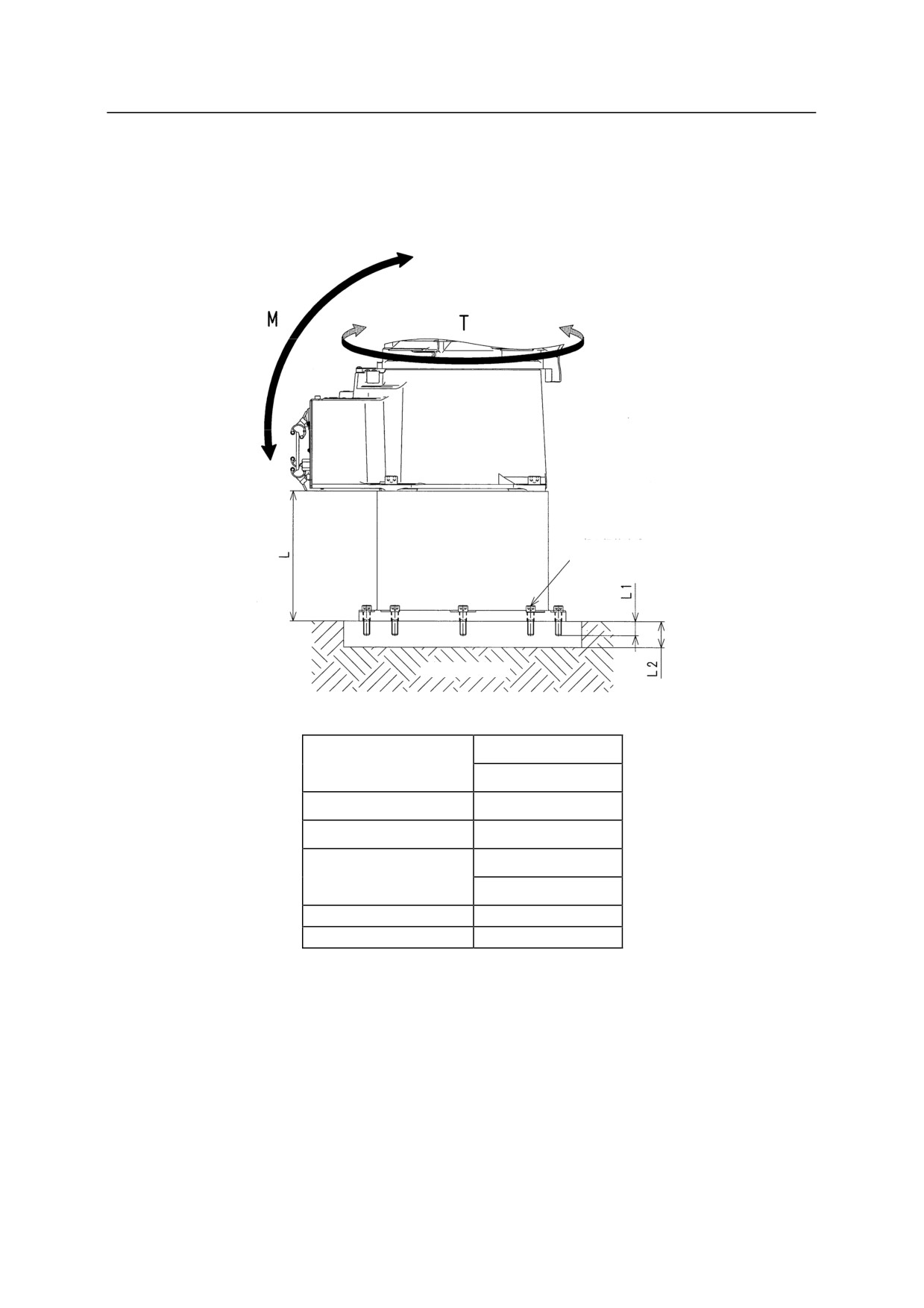
When Installing the Robot Pedestal on the Floor
In this case, the installation procedures are practically the same as the procedure shown in the
prior section.
Pedestal installation bolt
Steel
plate
Concrete
70 kg(L=600)
Pedestal mass
45 kg(L=300)
Pedestal installation bolt
8-M12
Tightening torque
98 Nm
600(60360-1166㸨)
L
300(60360-1167㸨)
L1
18 mm Min.
L2
20 mm Min.
NOTE* (
) indicates the part number of pedestal.
5-19
5. Installation
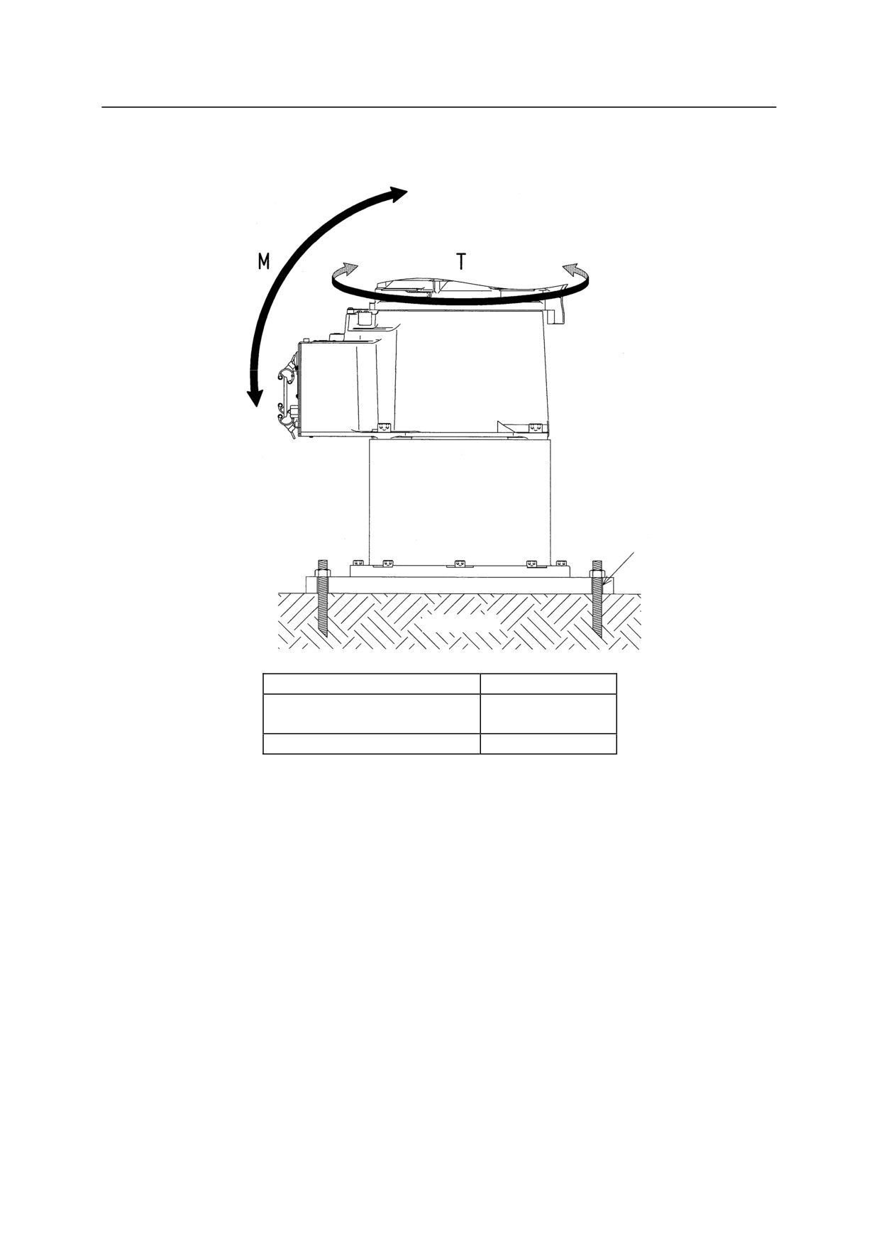
When Installing the Robot Base Plate on the Floor
Bolt hole
Base plate
Concrete
Base plate mass
110 kg
4-20
Base plate installation hole
(PCD800)
Base plate dimension (mm)
750 750 25
5-20
5. Installation
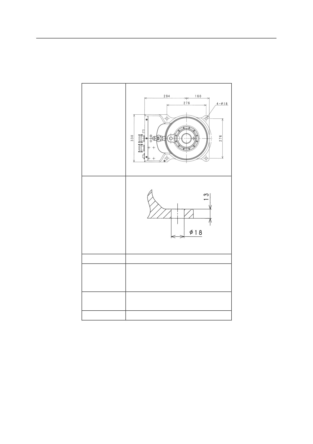
Installation Dimensions of Base Section
Fix the base section with high tension bolts through the bolt holes.
Dimensions for
installation
Cross-section
of installation
section
Bolt hole
4-18
4-M16
High tension
Material: SCM435
bolt
Strength class: 10.9 min.
Tightening
235 Nm
torque
Levelness
Within 5°
5-21
5. Installation
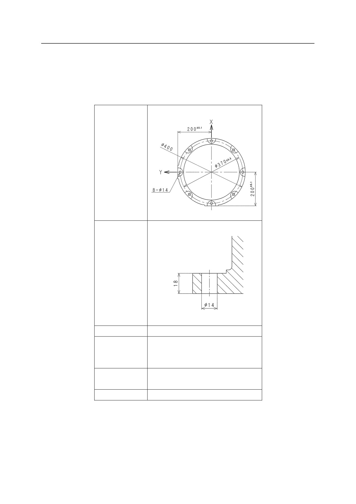
Installation Dimensions of Robot Pedestal
When installing a robot on the pedestal, fix the pedestal with high tension bolts through the bolt
holes.
Dimensions for
installation
Cross-section
of installation
section
Bolt hole
8-14
8-M12
High tension
Material: SCM435
bolt
Strength class: 10.9 min
Tightening
98 Nm
torque
Levelness
Within 5°
5-22