Kawasaki Robot (B, BA, CP, CX, M, MC, MS, R, Y, Z). Instruction Manual (2015) - page 4
4. Transportation
4.2 TRANSPORTATION OF CONTROLLER
When transporting the controller, strictly observe the precautions given in the sections below for
whichever transport method is chosen.
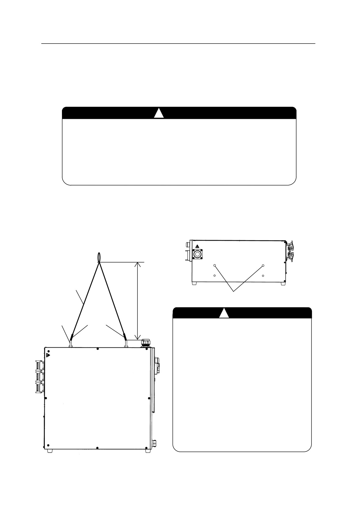
4.2.1 BY CRANE LIFTING
!
WARNING
1. Never support the controller manually when it is lifted up. And, never
go under or stay too close to the controller during transport.
2. Hook the wire at the lifting eyebolts as shown below.
3. Ensure that the lifting eyebolts are not loose. Check each one and
retighten if loose. Otherwise, the controller may fall and suffer damage.
E0x controller
Attach the following eyebolts to the M10 tapped holes in the figure below when transporting the
controller by crane lifting.
(Manufacturer: TAKIGEN MGF CO., LTD. Model: B-130-10 or
equivalent. The screw length should be 25 mm or less.)
Wire
M10 tapped hole
1 m or
more
Lifting
!
CAUTION
eyebolt
Hook
1. Prepare wire and crane capable of
hoisting 200 kg or more, sufficient for a
controller loaded with full options.
2. Remove the teach pendant and teach
pendant holder (if equipped) before
lifting with the wire sling.
3. Wire length: 1 m or more as shown in
the figure on the left.
4. Be careful as the controller may tilt
when lifted up.
5. Be careful not to let the wire to get
caught on other equipments.
4-3
4. Transportation
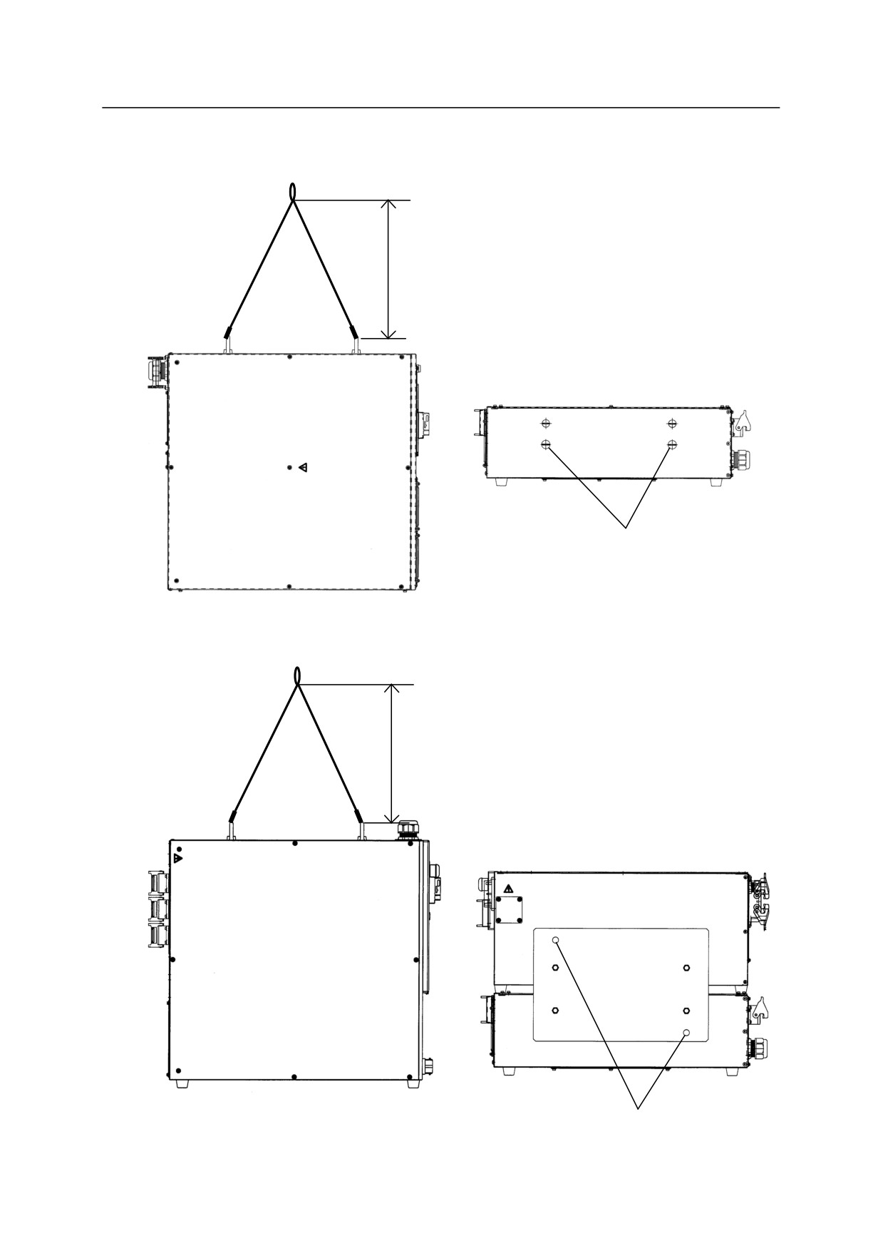
Transformer unit
1 m or
more
M10 tapped hole
Controller combined with transformer unit
1 m or
more
M10 tapped hole
4-4
4. Transportation
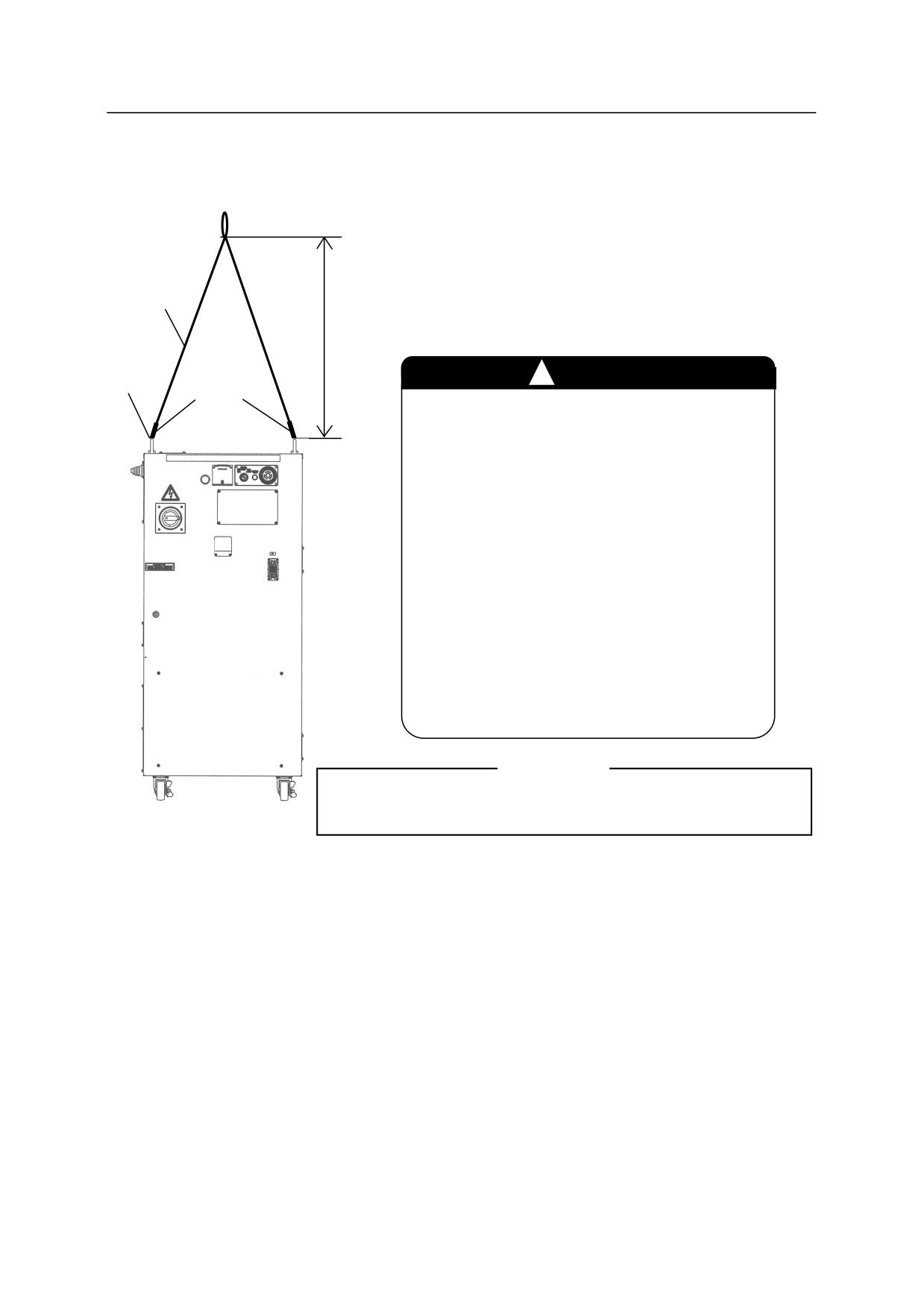
E4x controller
Wire
1 m or more
Lifting
!
CAUTION
eyebolt
Hook
1. Prepare wire and crane capable of
hoisting 300 kg or more, sufficient for
a controller loaded with full options.
2. Remove the teach pendant and teach
pendant holder (if equipped) before
lifting with the wire sling.
3. Wire length: 1 m or more as shown in
the figure on the left.
4. Be careful as the controller may tilt
when lifted up.
5. Be careful not to let the wire to get
caught on other equipments.
[ NOTE ]
E70/E71/E91 controllers must not be transported by crane lifting.
E4x controller
4-5
4. Transportation
4.2.2 BY CASTER (E4X)
!
WARNING
1. The controller can be moved on its casters only when the entire
transport path is level enough. Otherwise, moving the controller on
an inclined or an uneven surface will cause it to topple, resulting in a
serious damage.
2. E4x controller falls over if it is tilted as follows.
Back or forth: Approx. 15 or more
Right or left: Approx. 15 or more
CAUTION
!
1. Release the stoppers on the two front casters of the controller when
moving the controller.
(Push the “OFF” side pedal.)
2. Relock the casters after the transport is complete.
(Push the “ON” side pedal for locking.)
[ NOTE ]
E0x (or with transformer unit)/E70/E71/E91 controllers
must not be transported by caster.
4-6
4. Transportation
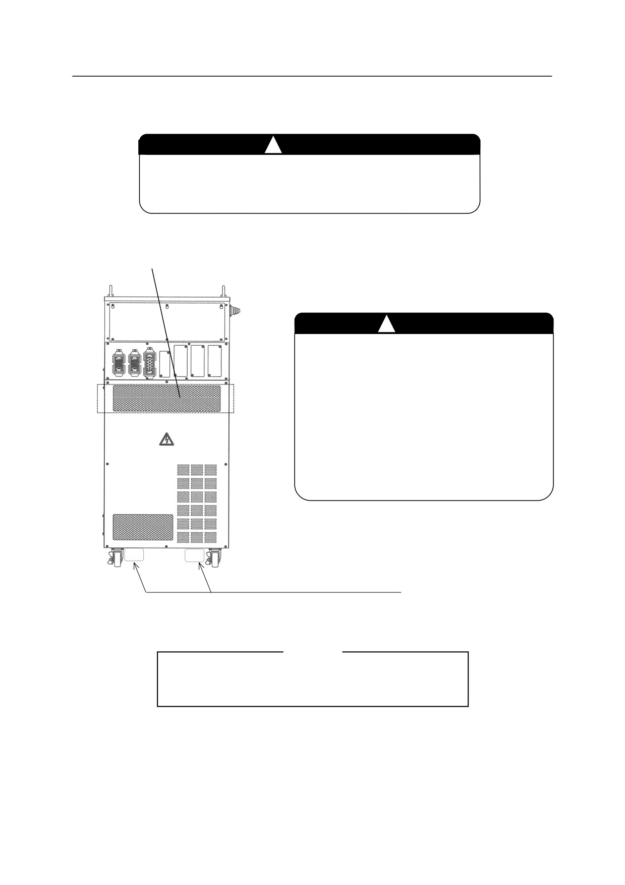
4.2.3 BY FORKLIFT TRUCK (E4X)
WARNING
!
To avoid the controller from toppling over, fasten it to
the forklift with a belt as shown below.
Falling prevention belt
CAUTION
!
1. Remove the teach pendant and teach
pendant holder. The fork cannot be
passed from the side. Pass the fork under
the controller body as shown on the left.
2. Be careful not give shock to the controller
during transport.
3. Be careful not to get caught on other
equipment, cables, etc.
Pass the fork through this position.
[ NOTE ]
E0x (or with transformer unit)/E70/E71/E91 controllers
must not be transported by forklift.
4-7
4. Transportation
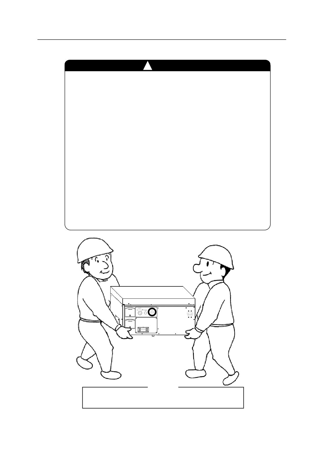
4.2.4
BY TWO PERSONS (E0X (OR WITH TRANSFORMER UNIT)/E70/E71/E91)
!
CAUTION
1. Disconnect the Teach Pendant.
2. Be careful not give shock on the controller during transportation.
3. The clearance between the bottom of the controller and the floor
is small (E70/E71: 9 mm, E0x/E91: 18 mm). Accordingly, hold
up one side of the controller then the other side, and get your
fingers placed on the bottom of controller body sufficiently
before holding up the controller. Because the controller has
mass (E70/E71: 30 kg, E01/E02/E04/E91: 40 kg, E03/transformer
unit: 45kg), it is impossible to carry the controller with fingertips.
On the left side of E70/E71 controller, handle is provided to hold
up the controller.
4. It is impossible to carry the control equipment by two persons
when the controller is combined with the transformer unit,
because the total mass is 90 kg. Carry the control equipment by
crane lifting or carry the controller and the transformer unit
separately after disconnecting them.
[ NOTE ]
E4x controllers must not be carried manually.
4-8
4. Transportation
4.3 TRANSPORTATION METHOD OF ROBOT ARM
!
CAUTION
1. When lifting up the robot, be careful as robot may tilt forward/backward
depending on robot posture and installation condition of the options. If the
robot is lifted up in an inclined posture, it may swing or damage. Also, the wire
may interfere with the harness, piping etc., or it may damage due to interfering
with surrounding objects.
2. Remove the eyebolt or the hoisting jig or the transportation jig attached to the
arm once the transportation of robot is complete.
3. Protect the robot with guard plates, etc. if wires interfere with a part of the robot.
4.3.1 B SERIES
Using Wire Sling (Using hoisting jig)
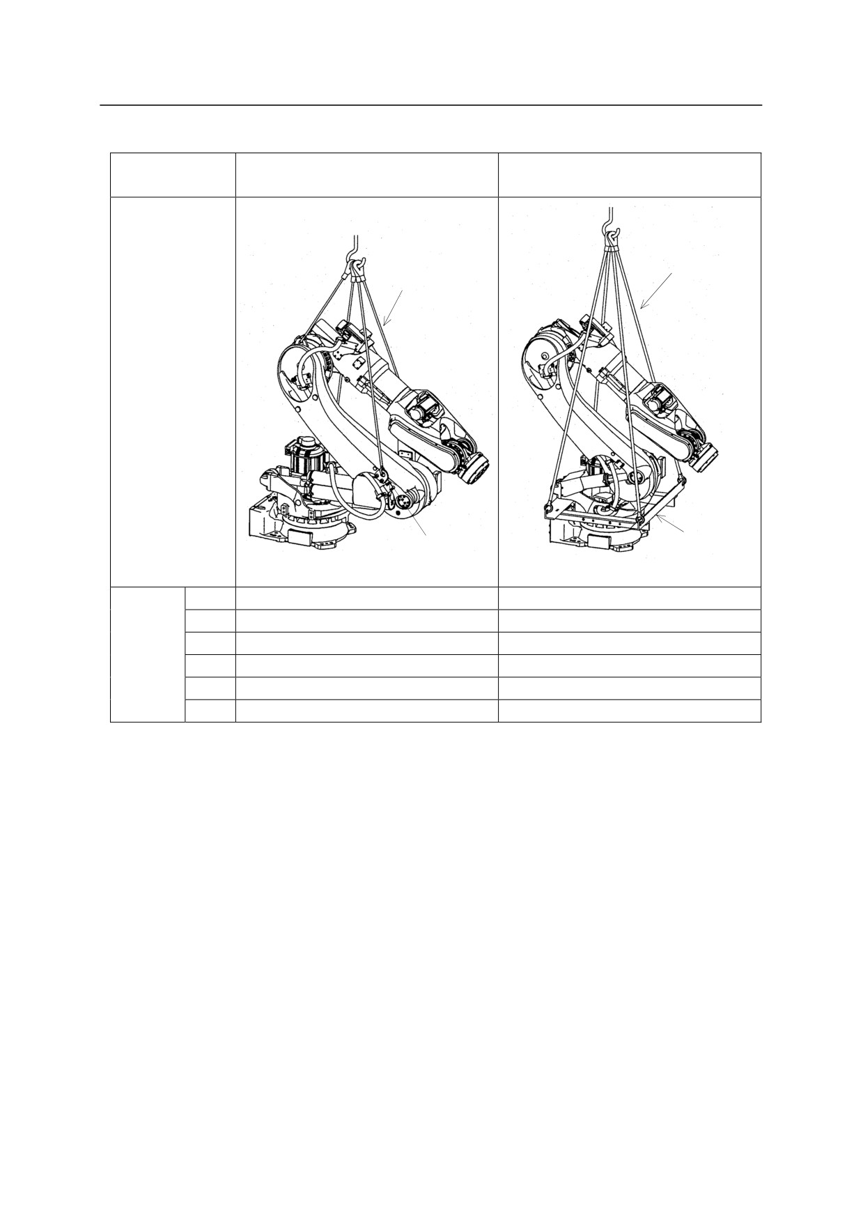
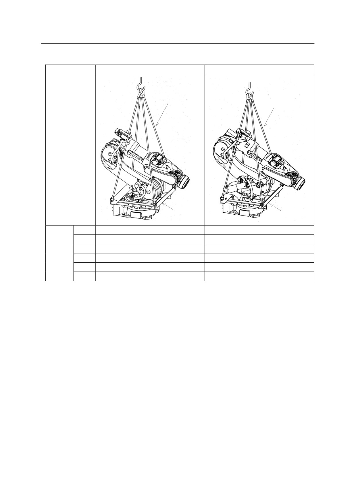
As shown in the figure below, hoist up the robot by fastening the wire slings to the hoisting jig
attached to robot arm.
!
WARNING
Use a hoisting jig without fail when hoisting up robot. If the robot is
hoisted up without using the jig, robot may fall.
4-9
4. Transportation
BX100L, BX130X,
Model
BT165L, BT200L
BX165L, BX200L
4 Wires
4 Wires
Hoisted
up
posture
Hoisting
Hoisting
jig
jig
JT1
0°
0°
JT2
-130°
-35°
Hoisted
JT3
-75°
-75°
up
JT4
0°
0°
posture
JT5
0°
0°
JT6
0°
0°
4-10
4. Transportation
Model
BX100N
BX165N
4 Wires
4 Wires
Hoisted
up
posture
Hoisting
Hoisting
jig
jig
JT1
0°
0°
JT2
-50°
-45°
Hoisted
JT3
-77°
-75°
up
JT4
0°
0°
posture
JT5
0°
0°
JT6
0°
0°
4-11
4. Transportation
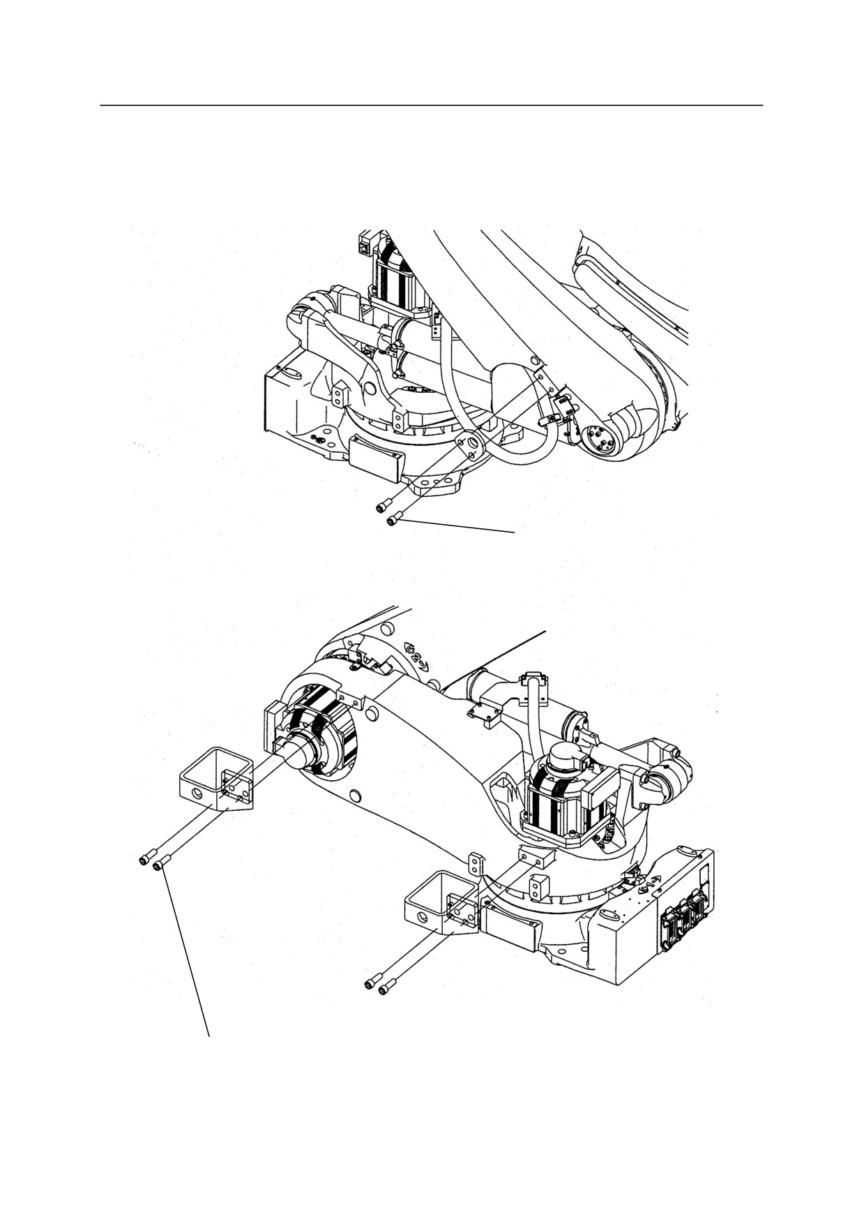
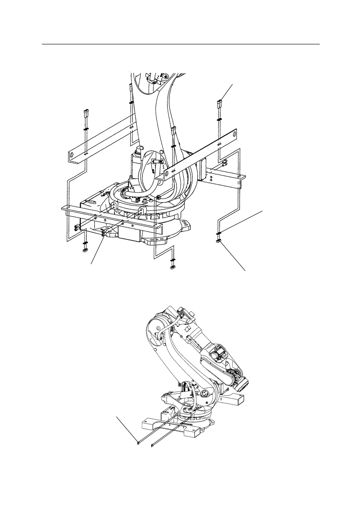
Attach the hoisting jig as shown in the figure below.
BT165L, BT200L
Hexagon socket head bolt
M16 x 40 (2 bolts)
Tightening torque: 235.2 N·m
Hexagon socket head bolt
M16 x 50 (4 bolts)
Tightening torque: 235.2 N·m
4-12
4. Transportation
BX100L, BX100N, BX130X, BX165L, BX165N, BX200L
Hexagon socket head bolt
M12 x 40 (8 bolts)
Tightening torque: 98 N·m
Plain washer
(16 washers)
Hexagon socket head bolt
M12 x 35 (8 bolts)
Hexagon nut M12
Tightening torque: 98 N·m
(8 nuts)
or
Hexagon socket head bolt
M12 x 30 (8 bolts)
Tightening torque: 98 N·m
4-13
4. Transportation
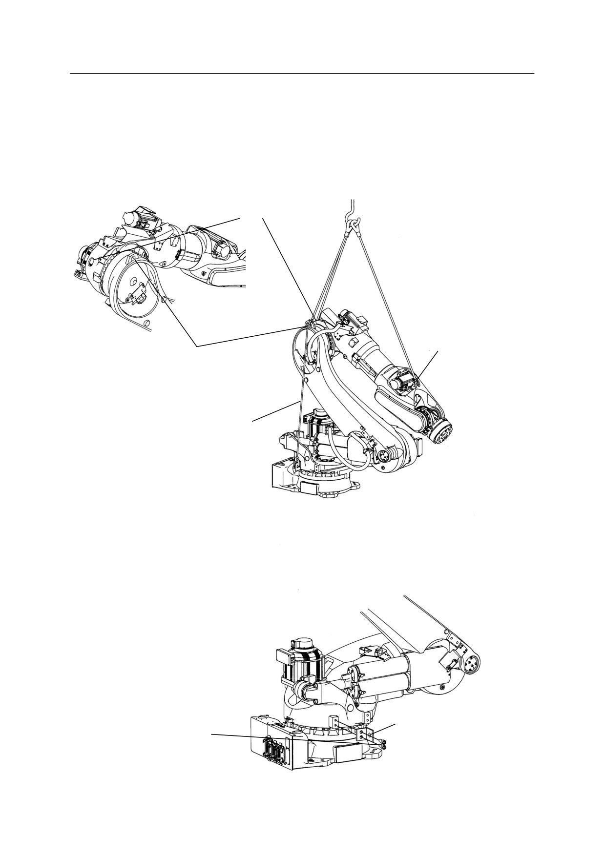
Using Wire Sling (Fastening wire sling directly on the arm)
BT165L, BT200L
Hoist up the robot arm with wire slings by hooking at the three hoisting holes of the arm shown in
the figure below and hooking the sling to prevent base section from dropping at the one hoisting
hole of the arm and the one hoisting hole of the jig (Manufactured by TAIYO, Name: V-hook,
Nominal working load: 1.25t or equivalent).
Hoisting hole
Hoisting hole
Hoisting hole
Sling to prevent base section
from dropping mounting
point
Sling to prevent base section from
dropping
(with shackles at both ends)
Sling to prevent base section
Hexagon socket head bolt
from dropping mounting point
M16 x 35 (2 bolts)
Sling to prevent base section
Tightening torque: 235.2 N·m
from dropping fixing jig
4-14
4. Transportation
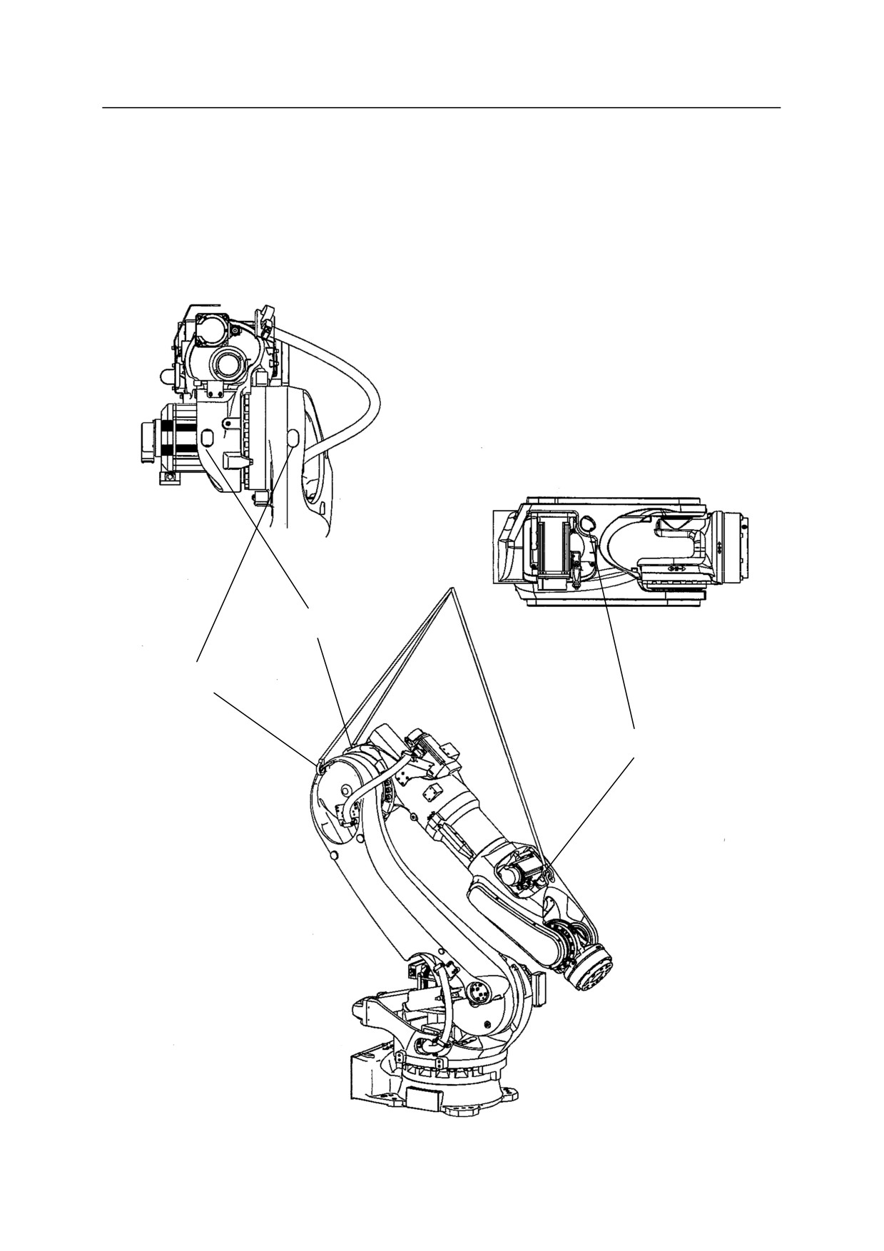
BX100L, BX130X, BX165L, BX200L
Hoist up the robot arm with wire slings by hooking at the three hoisting holes of the arm shown in
the figure below. (Manufactured by TAIYO, Name: V-hook, Nominal working load: 1.25t or
equivalent)
Hoisting hole
Hoisting hole
Hoisting hole
4-15
4. Transportation
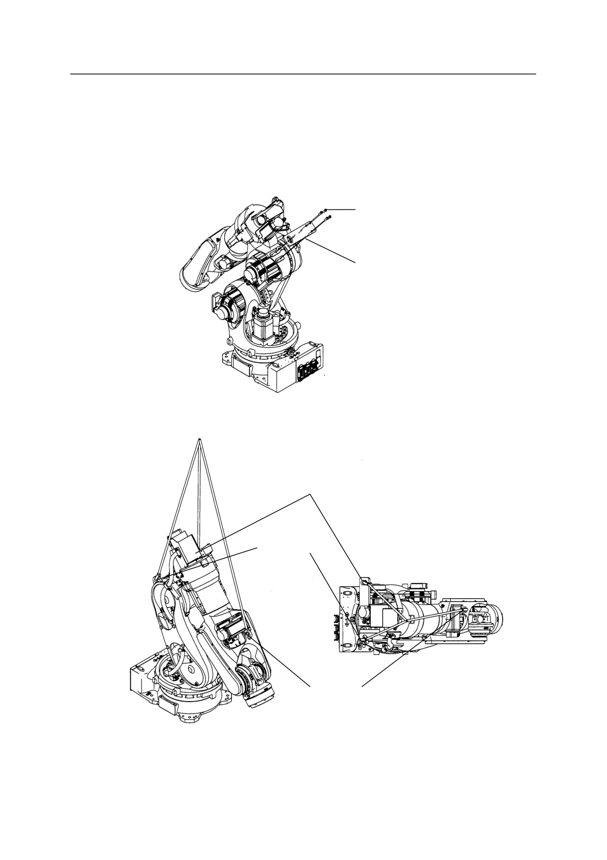
BX100S
Hoist up the robot arm with wire slings by hooking at the two hoisting holes of the arm and one
hoisting hole of hoisting jig shown in the figure below. (Manufactured by TAIYO, Name:
V-hook, Nominal working load: 1.25t or equivalent)
Hexagon socket head bolt
M12 x 40 (4 bolts)
Tightening torque: 98 N·m
Hoisting jig
Hoisting hole
Hoisting hole
Hoisting hole
4-16
4. Transportation
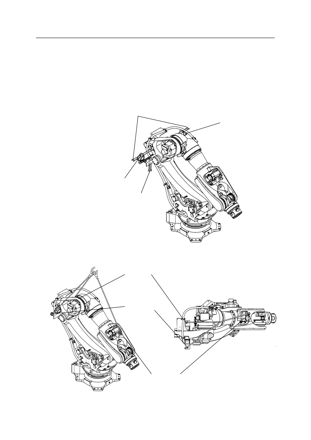
BX250L, BX300L
Hoist up the robot arm with wire slings by hooking at the one hoisting hole of the arm and two
hoisting holes of hoisting jig shown in the figure below. (Manufactured by TAIYO, Name:
V-hook, Nominal working load: 1.25t or equivalent)
Hexagon socket head bolt
M12 x 25 (4 bolts)
Tightening torque: 98 N·m
Hoisting jig
Hoisting jig
Hexagon socket head bolt
M8 x 20 (8 bolts)
Tightening torque: 29.4 N·m
Hoisting hole
Hoisting hole
Hoisting hole
4-17
4. Transportation
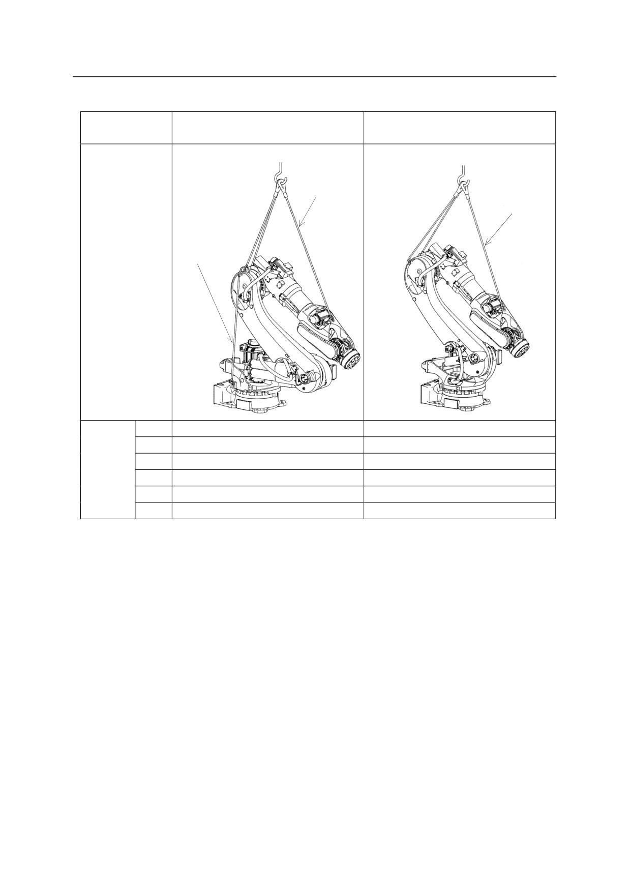
BX100L, BX130X,
Model
BT165L, BT200L
BX165L, BX200L
3 Wires
3 Wires
Sling to prevent
base section
from dropping
Hoisted
up
posture
JT1
0°
0°
JT2
-130°
-35°
Hoisted
JT3
-75°
-75°
up
JT4
0°
0°
posture
JT5
0°
0°
JT6
0°
0°
4-18
4. Transportation
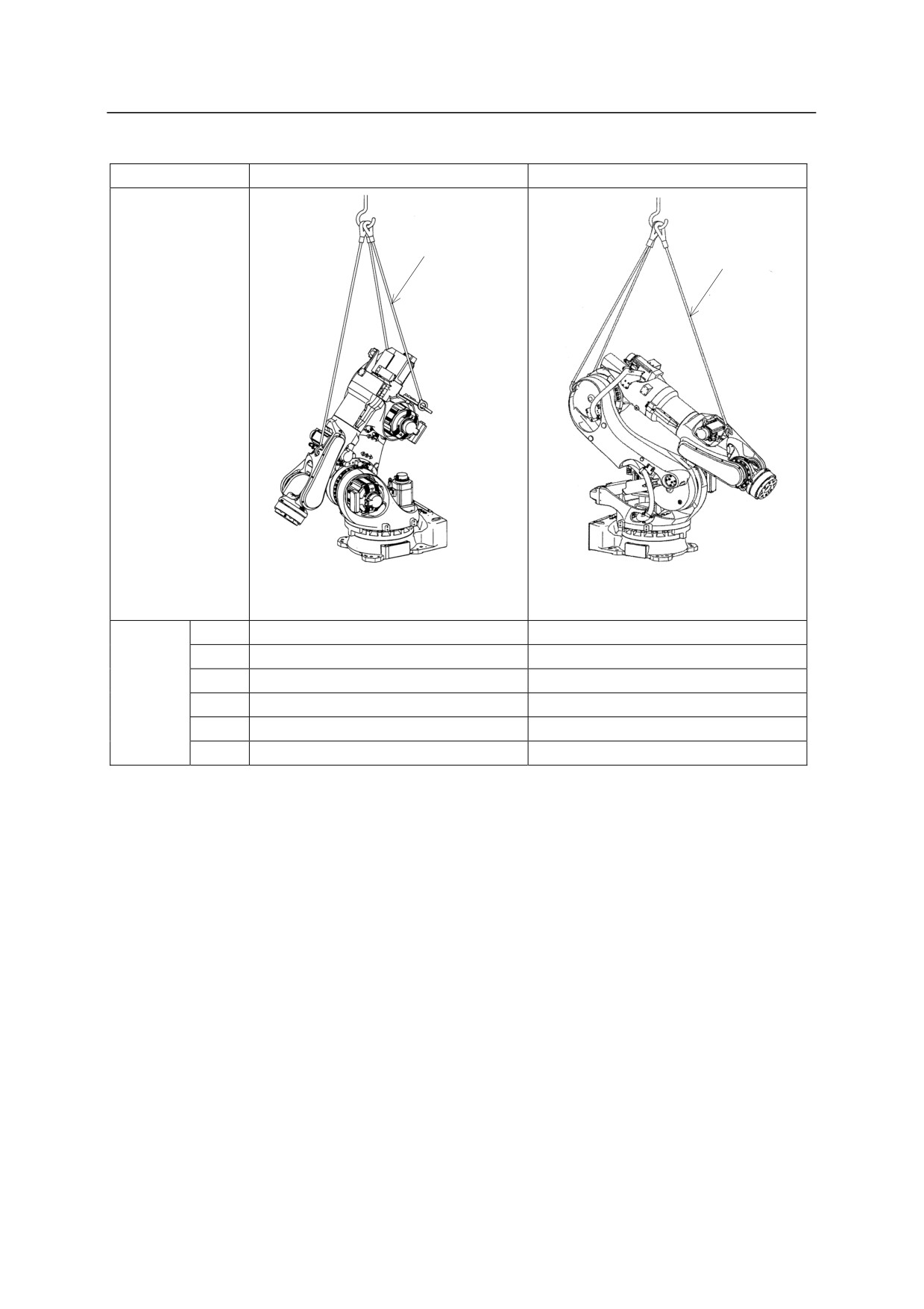
Model
BX100S
BX165N
3 Wires
3 Wires
Hoisted
up
posture
JT1
0°
0°
JT2
-30°
-45°
Hoisted
JT3
-81°
-75°
up
JT4
0°
0°
posture
JT5
0°
0°
JT6
0°
0°
4-19
4. Transportation
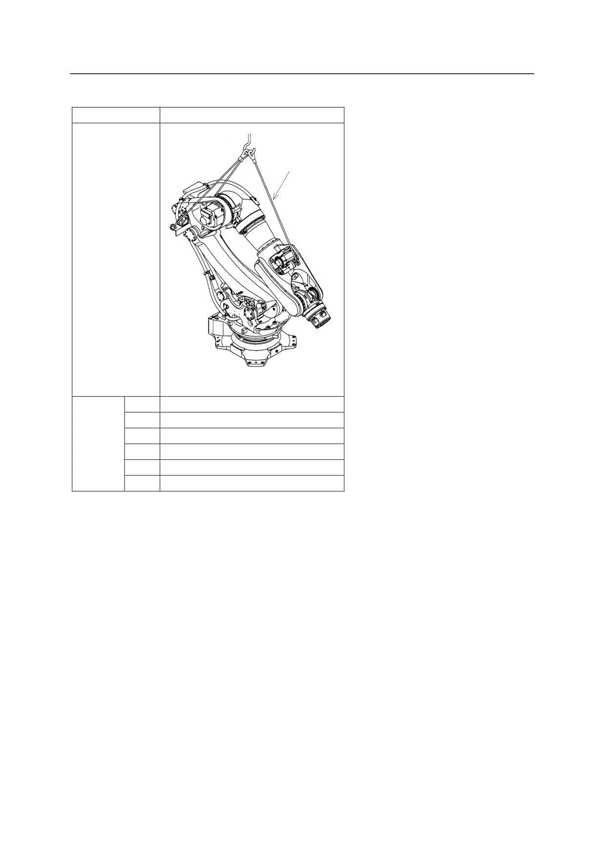
Model
BX250L, BX300L
3 Wires
Hoisted
up
posture
JT1
0°
JT2
-40°
Hoisted
JT3
-35°
up
JT4
0°
posture
JT5
0°
JT6
0°
4-20
4. Transportation
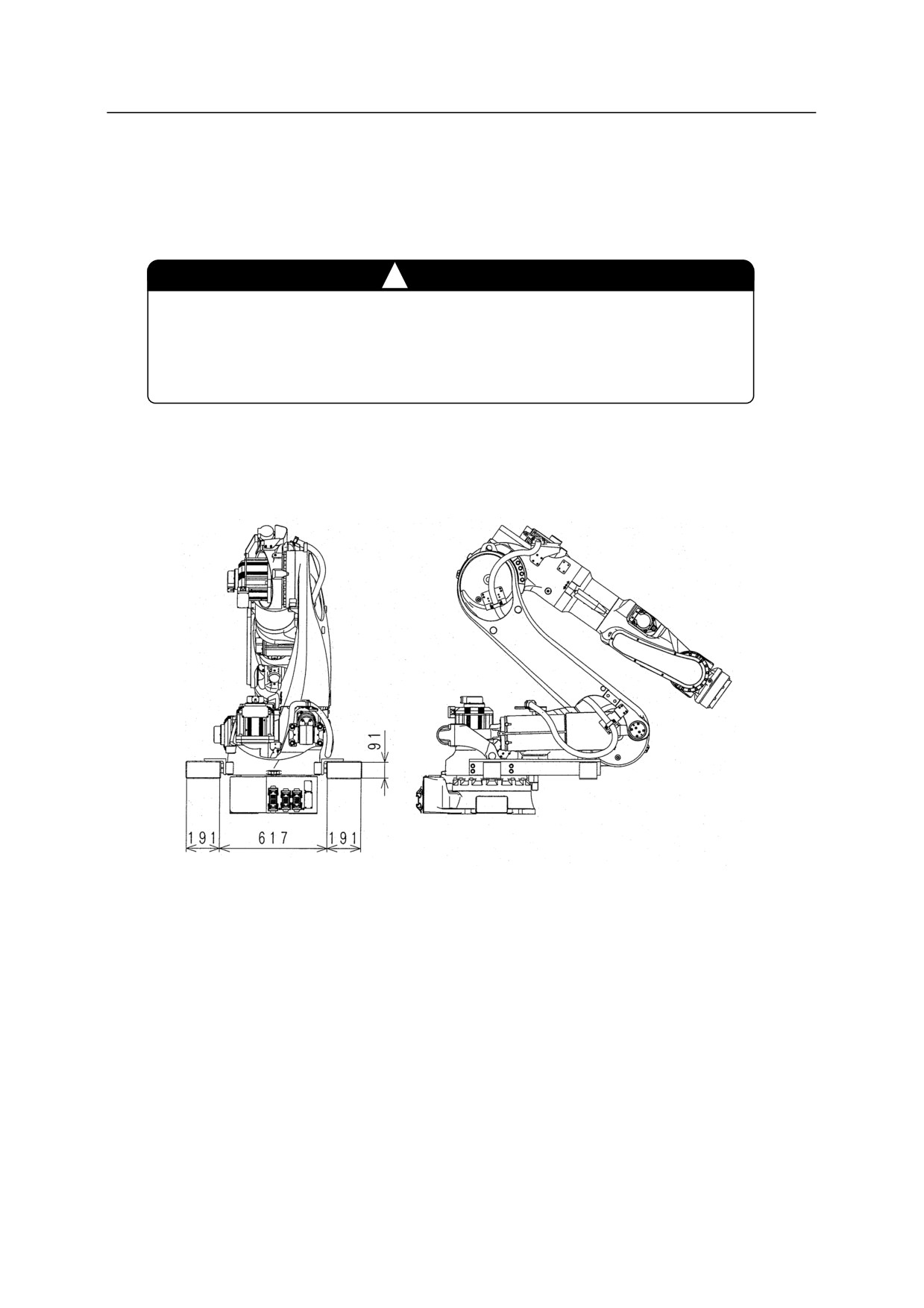
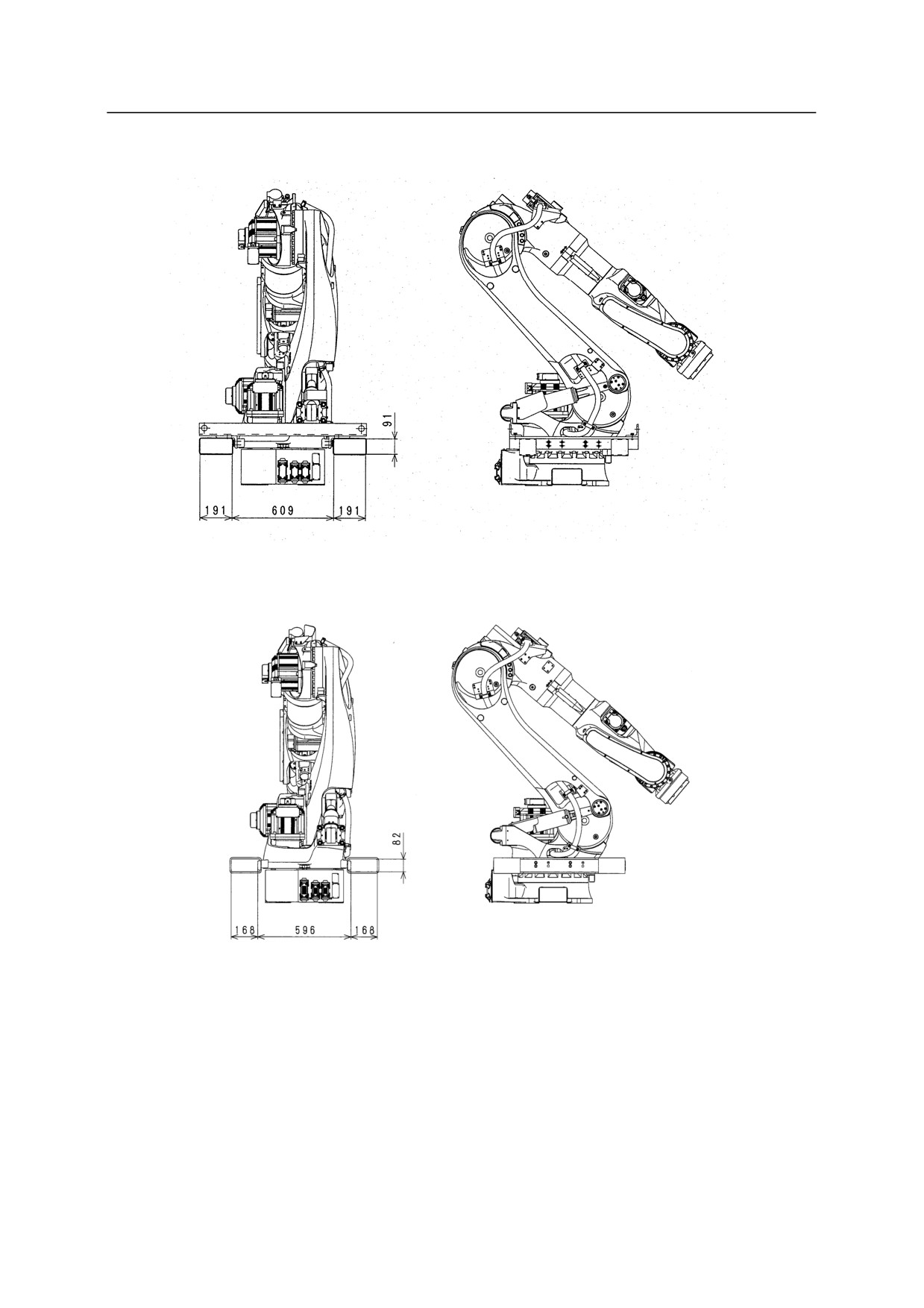
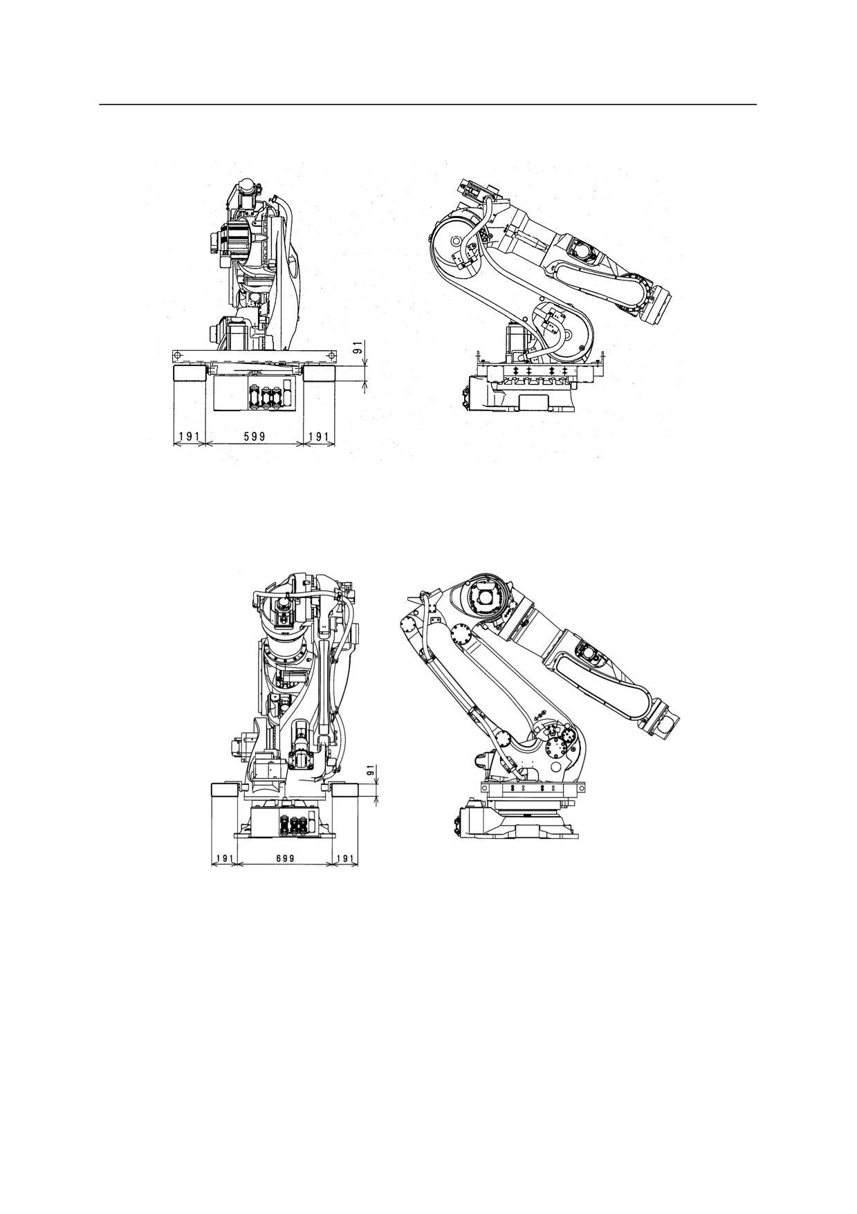
Using Forklift
According to the figure below, transport the robot by using a transportation jig for forklift
attached to the robot arm.
!
CAUTION
1. Confirm that the forks of forklift penetrate sufficiently without fail.
2. When transporting robot on an inclined or rough surface, be careful
to maintain balance to prevent forklift/robot from falling.
BT165L, BT200L
4-21
4. Transportation
BX100L, BX130X, BX165L, BX165N, BX200L
or
4-22
4. Transportation
BX100N, BX100S
BX250L, BX300L
4-23
4. Transportation
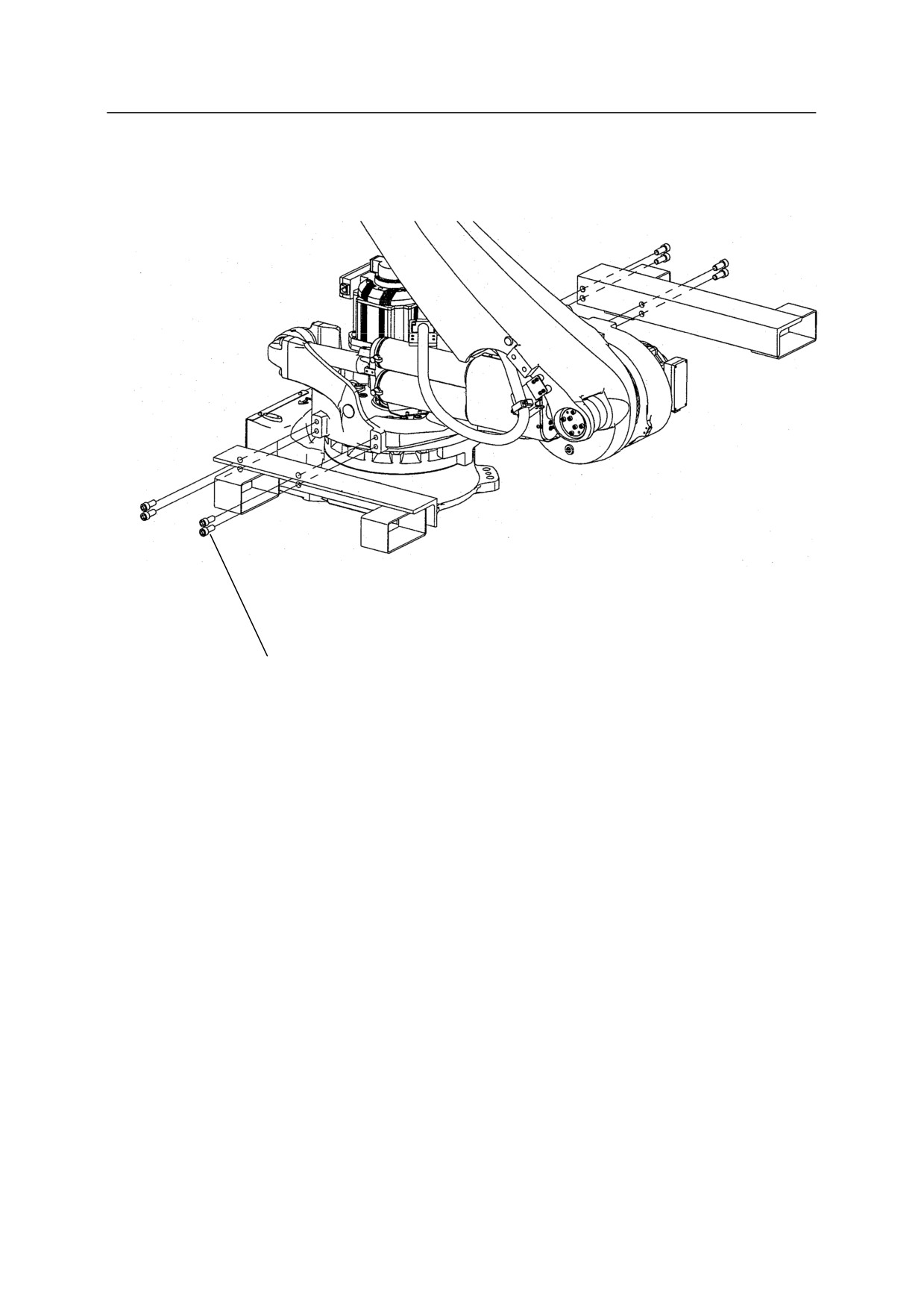
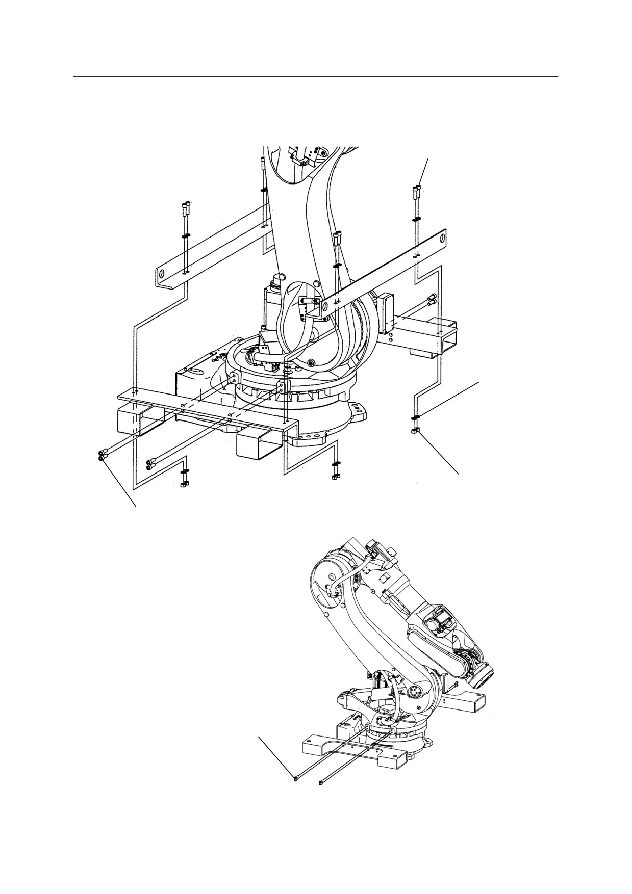
Attach the transportation jig as shown in the figure below.
BT165L, BT200L
Hexagon socket head bolt
M16 x 40 (8 bolts)
Tightening torque: 235.2 N·m
4-24
4. Transportation
BX100L, BX100N, BX100S, BX130X, BX165L, BX165N, BX200L, BX250L, BX300L
Hexagon socket head bolt
M12 x 40 (8 bolts)
Tightening torque: 98 N·m
Plain washer
(16 washers)
Hexagon nut M12
(8 nuts)
Hexagon socket head bolt
M12 x 35 (8 bolts)
Tightening torque: 98 N·m
Hexagon socket head bolt
M12 x 30 (8 bolts)
Tightening torque: 98 N·m
4-25
4. Transportation
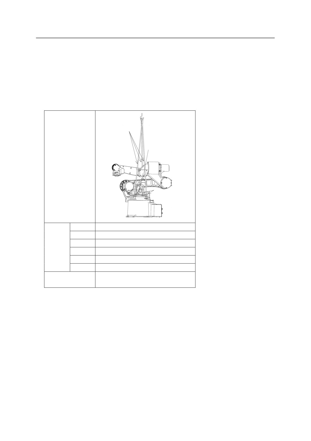
4.3.2 BA SERIES
Using Wire Sling (Without base plate)
As shown in the figure below, fasten wire slings to two eyebolts and a hoisting plate on the arm
and hoist up the robot. (Use the same method for hoisting up the robot with pedestal.)
3 Wires
1 Hoisting plate
Hoisted
up
posture
2 Eyebolts
JT1
0°
JT2
-85°
Hoisted
JT3
-175°
up
JT4
0°
posture
JT5
-90°
JT6
0°
Eyebolt M8 × 2
Hoisting parts on arm
Hoisting plate × 1
4-26
4. Transportation
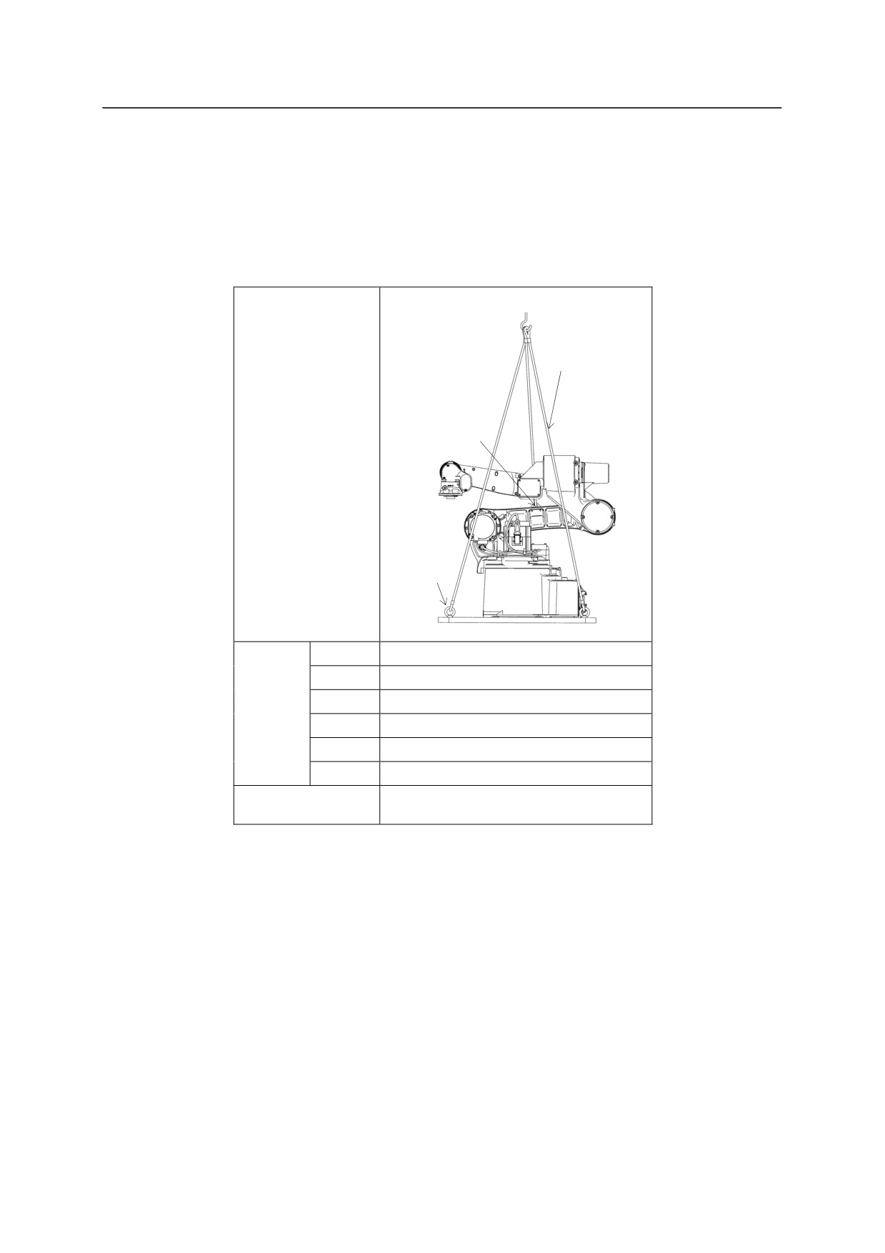
Using Wire Sling (With base plate)
According to the figure below, hoist up the robot by fastening four wire slings to four eyebolts on
the base plate. In addition, fasten wire slings to a hoisting plate on the arm to prevent the robot
from accidentally falling. (Use the same method for hoisting up the robot with pedestal.)
5 Wires
1 Hoisting plate
Hoisted
up
posture
4 Eyebolts
JT1
0㼻
JT2
-85㼻
Hoisted
JT3
-175㼻
up
JT4
0㼻
posture
JT5
-90㼻
JT6
0㼻
Hoisting parts on arm
Hoisting plate × 1
4-27
4. Transportation
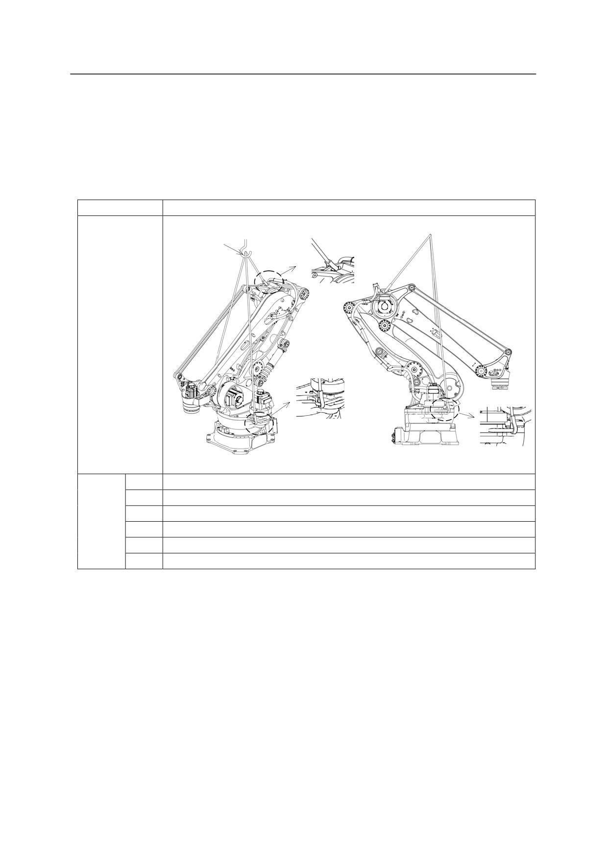
4.3.3 CP SERIES
Using Wire Sling
Hoist up the robot arm by fastening wire slings directly to the three hoisting holes of the arm
shown in the figure below.
Model
CP series
3 Wires
Hoisted
up
posture
JT1
0°
JT2
-46°
Hoisted
JT3
-34°
up
JT4
0°
posture
JT5
0°
JT6
0°
4-28
4. Transportation
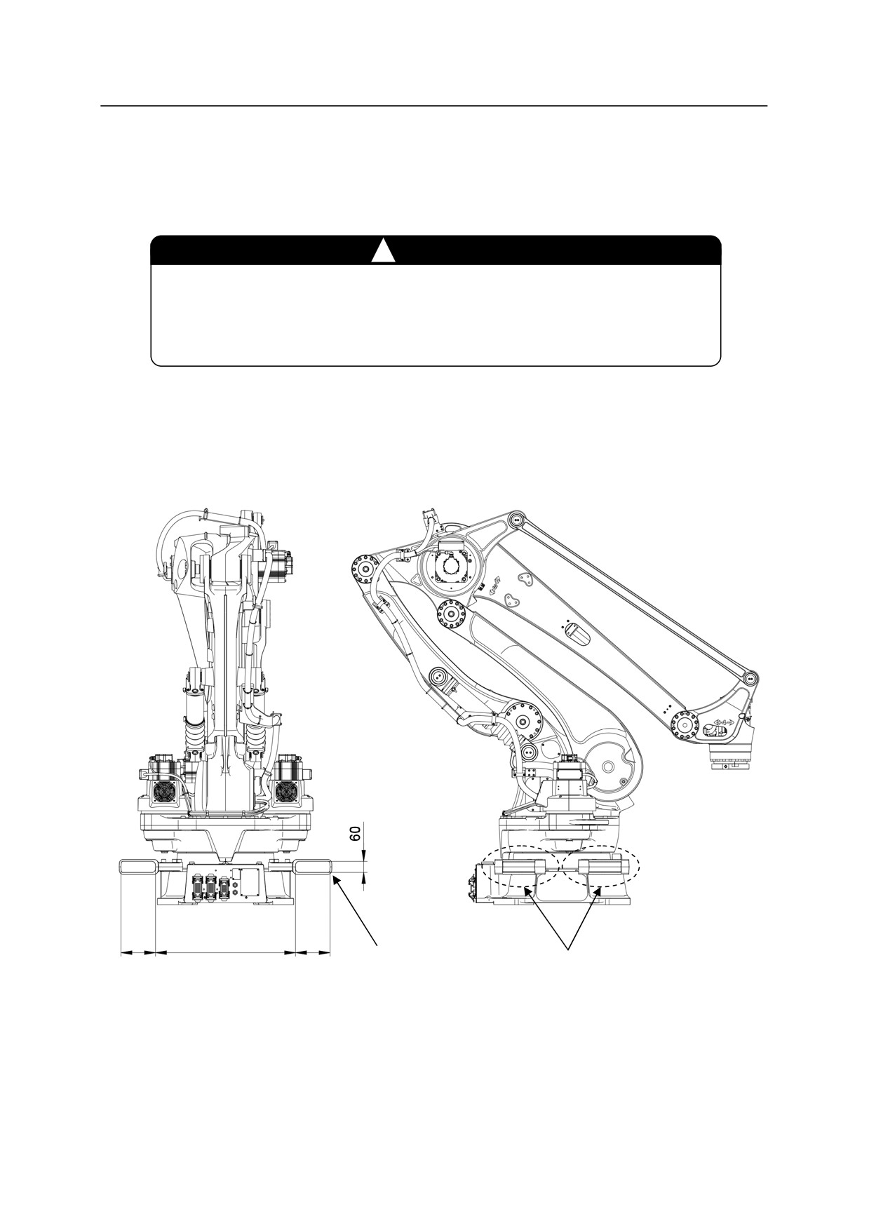
Using Forklift
According to the figure below, transport the robot by using a transportation jig for forklift
attached to the robot arm.
!
CAUTION
1. Confirm that the forks of forklift penetrate sufficiently without fail.
2. When transporting robot on an inclined or rough surface, be careful
to maintain balance to prevent forklift/robot from falling.
190
770
190
Fork pocket
Fork pocket
4-29
4. Transportation
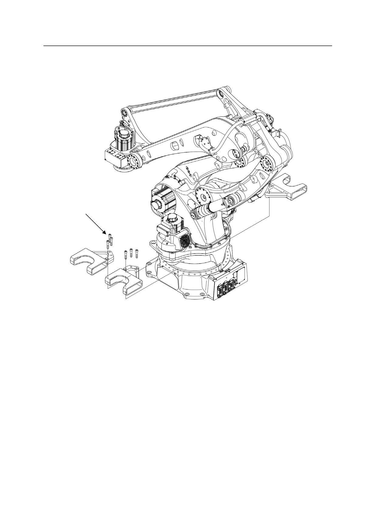
Attach the transportation jig as shown in the figure below.
Hexagon socket head bolt
M16 x 75 (12 bolts)
Tightening torque: 235 N·m
4-30
4. Transportation
4.3.4 M SERIES
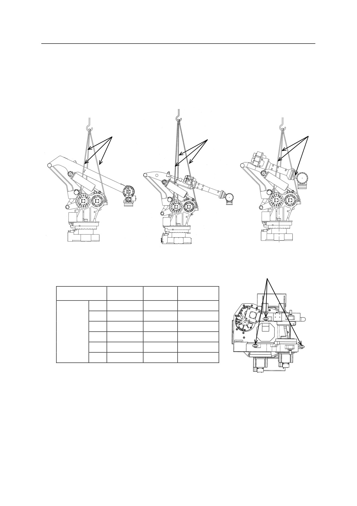
Using Wire Sling
Attach three eye bolts on the arm as shown in the figure below. Fasten the wires through the
eyebolts to lift the robot arm.
3 Wires
3 Wires
3 Wires
MD Series
MT400N
MX Series
Eyebolts
Model
MD Series
MT400N
MX Series
JT1
0
0
0
JT2
-45
70
-45
Hoisted
JT3
-20
-135
-23
up
JT4
0
0
0
posture
JT5
0
70
0
JT6
0
0
䠉
4-31
4. Transportation
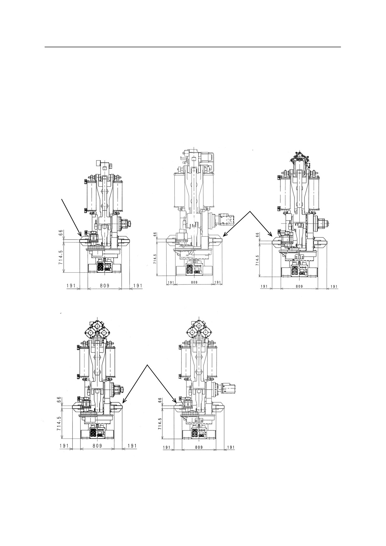
Using Forklift
Fork pocket comes as an optional jig to use when lifting the robot with a forklift.
1. When carrying MX or MD series robot by forklift, JT 2 should be at the angle of 0° to - 45°.
2. When carrying MT400N by forklift, JT 2 should be at the angle of -135°.
3. Confirm that the forks of forklift penetrate sufficiently without fail.
4. When transporting robot on an inclined or rough surface, be careful to maintain balance to
prevent forklift/robot from falling.
Fork pocket
Fork pocket
MD400N
MD500N
MT400N
Fork pocket
MX350L, MX420L, MX500N
MX700N
4-32
4. Transportation
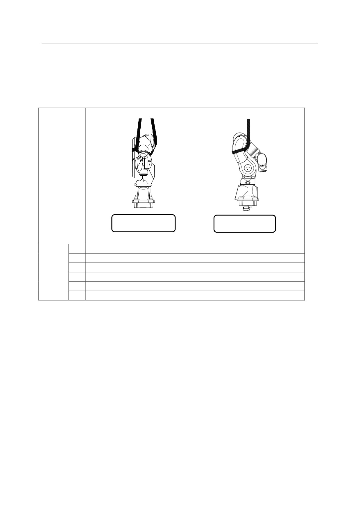
4.3.5 MC SERIES
There are no service tapped holes for hoisting the robot with wire. Therefore, secure a belt
around the rear arm to hoist up the robot.
Hoisted
up
posture
Front
Side
JT1
0°
JT2
-15°
Hoisted
JT3
-150°
up
JT4
0°
posture
JT5
-40°
JT6
0°
4-33
4. Transportation
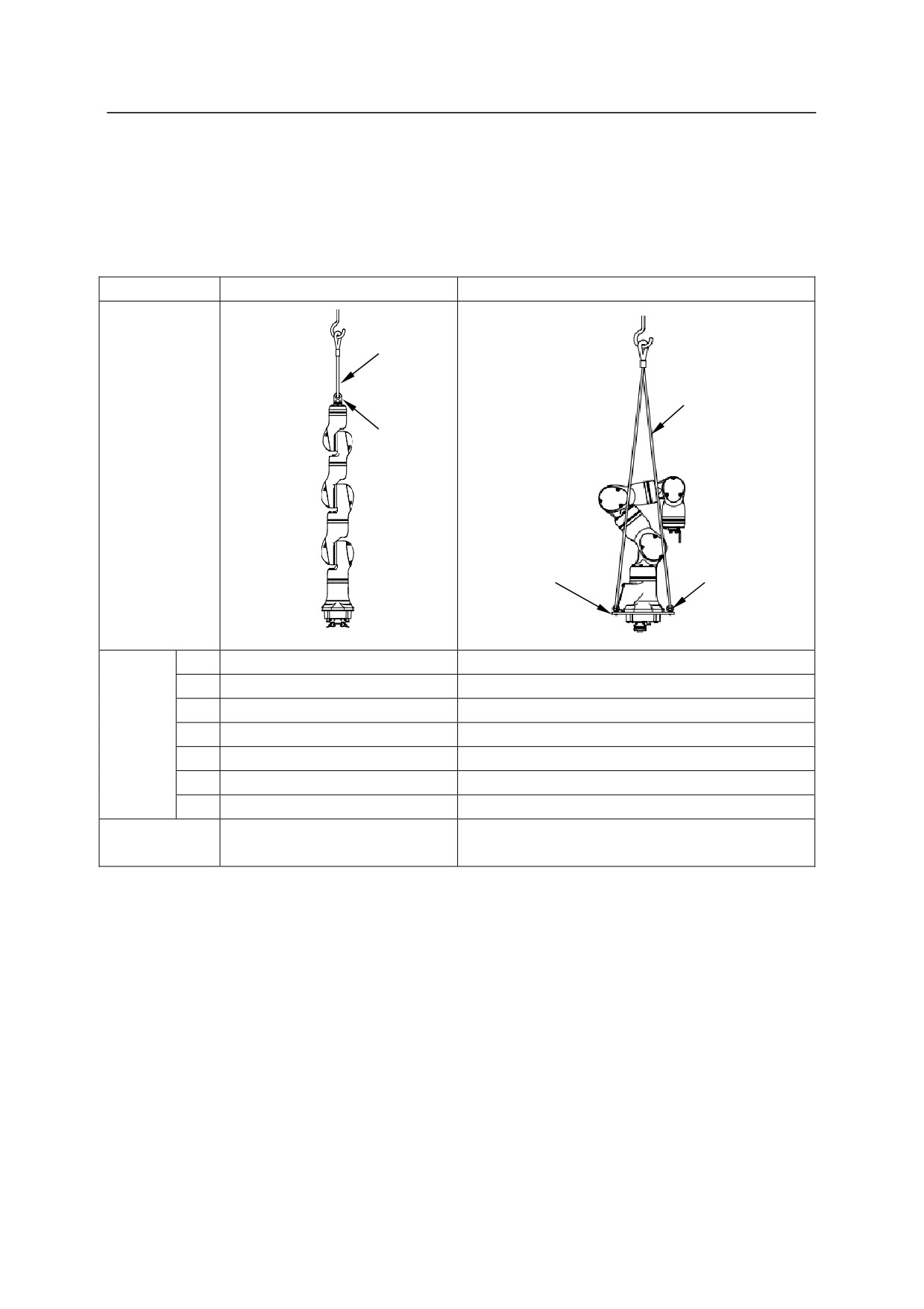
4.3.6 MS SERIES
Attach a hoisting jig or eyebolts on arm or base plate as shown in the figure, and hoist up the
robot with wires.
Model
MS005N
MS005N (with base plate)
Wire
Wire
Hoisting
Hoisted
jig
up
posture
Base plate
4 Eyebolts
JT1
0°
0°
JT2
0°
-40°
Hoisted
JT3
0°
-120°
up
JT4
0°
0°
posture
JT5
0°
-100°
JT6
0°
0°
JT7
0°
0°
60154-3715 (jig, hoisting)
60333-7009 (plate, base)
Hoisting jig
RSBM616Z×4
0EBM8Z (eyebolt)×4
4-34
4. Transportation
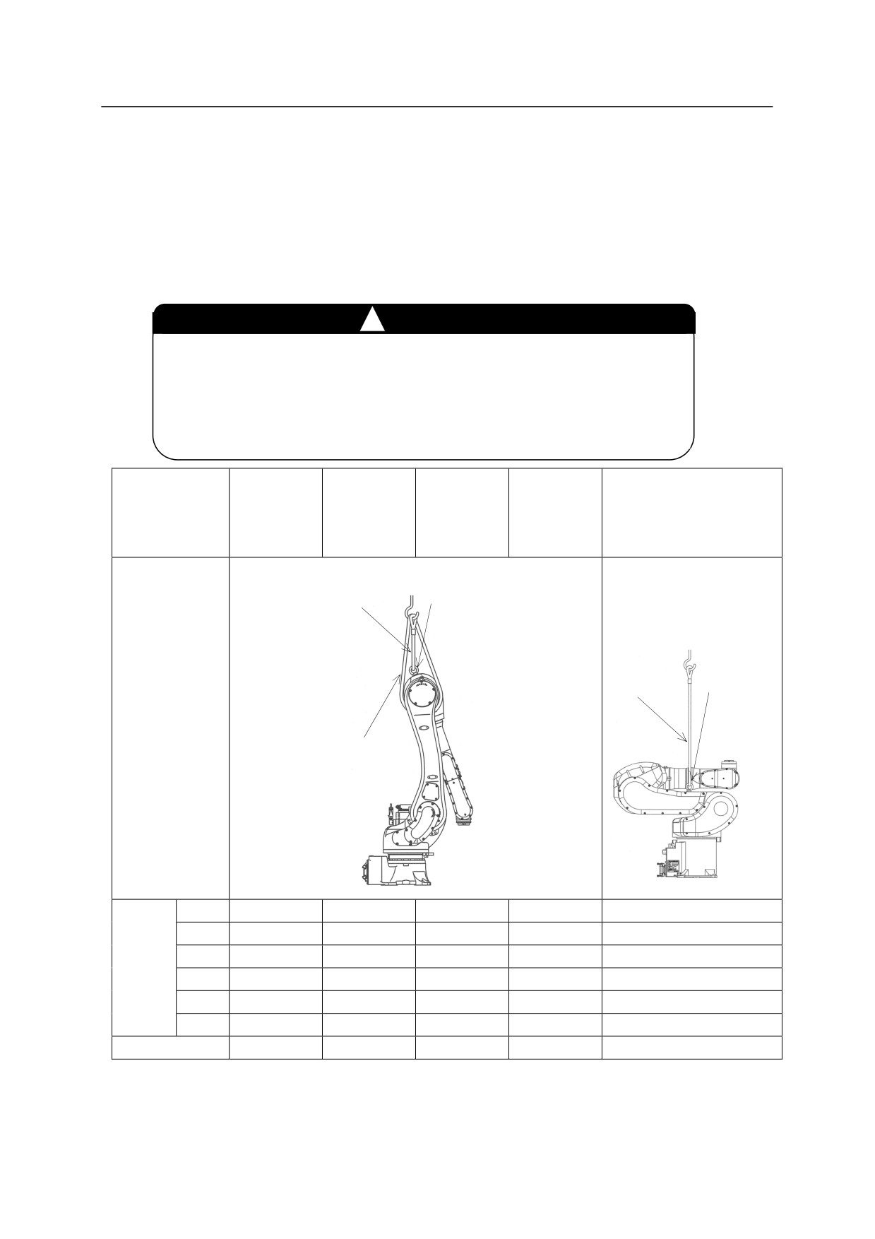
4.3.7 R SERIES
Using Wire Sling (Without base plate)
As shown in the figure below, hoist up the robot by fastening a wire sling to the eyebolt attached
to robot arm. (Use the same method for hoisting up the robot with pedestal.)
!
WARNING
When lifting up the R series arm with a wire sling, support the arm
with an additional wire to avoid the arm from rotating.
(Except
RC05L/RS05L/RS05N.) The eyebolt may loosen and cause the robot
to fall if the arm rotates when lifted.
RA06L
RA10L
RD80N
RA10N
RA20N
RS30N
Model
RS15X
RC05L, RS05L, RS05N
RS06L
RS10L
RS50N
RS10N
RS20N
RS80N
1 Eyebolt
1 Wire
2 Eyebolts
2 Wires
Hoisted
up
posture
1 Anti-rotation wire
JT1
0°
0°
0°
0°
0°
JT2
0°
-3°
0°
1°
-80°
Hoisted
JT3
-163°
-163°
-155° (-55°)
-155°
-170°
up
JT4
0°
0°
0°
0°
0°
posture
JT5
-17°
-20°
-25° (0°)
-114°
90°
JT6
0°
0°
0°
0°
0°
Eyebolt for arm
M16×1
M16×1
M24×1
M24×1
M8×2
(
): RD80N
4-35