Kawasaki Robot (B, BA, CP, CX, M, MC, MS, R, Y, Z). Instruction Manual (2015) - page 6
5. Installation
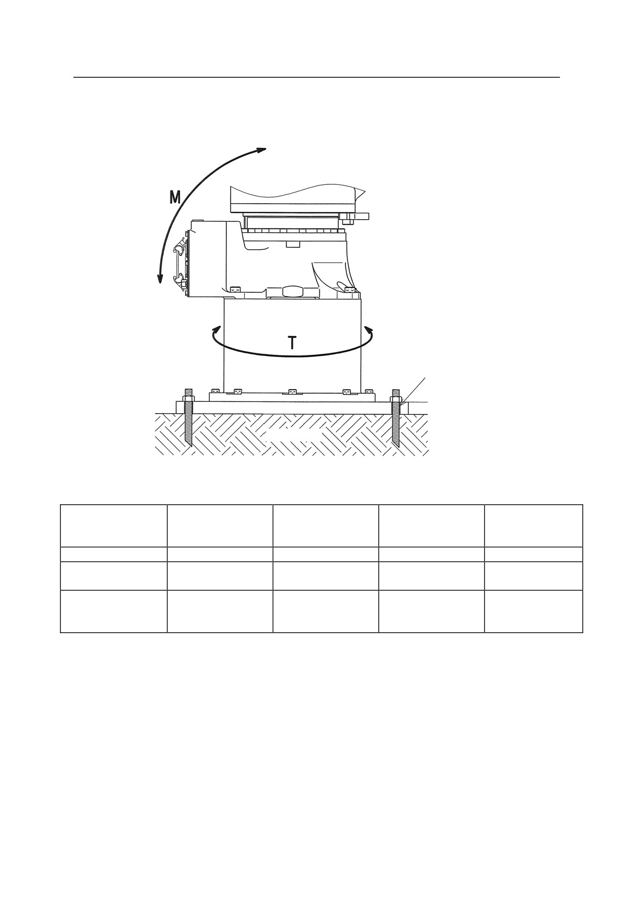
5.3.2.3 INSTALLING CP SERIES ARMS
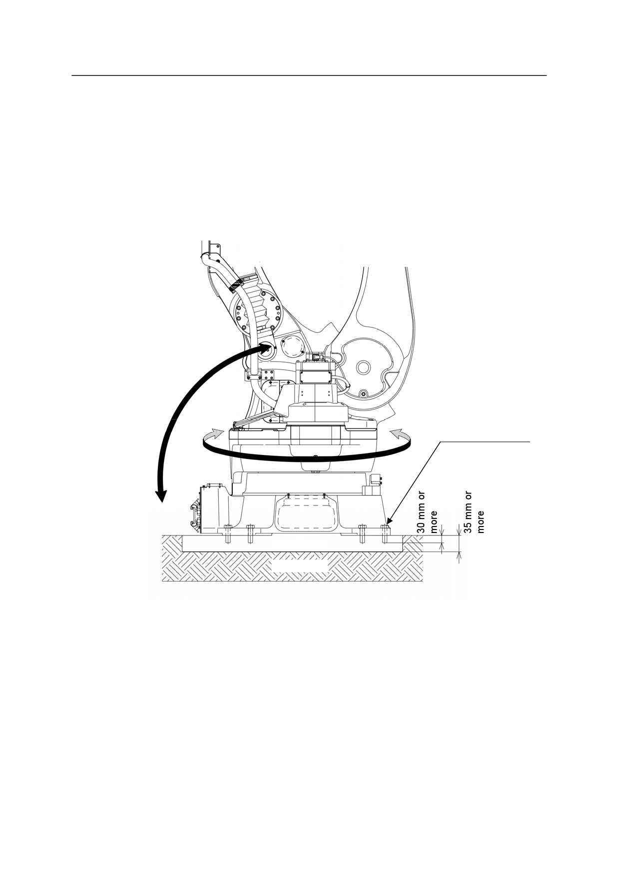
When Installing the Base Directly on the Floor
Bury a steel plate (35 mm Min. thick) in the concrete floor as shown in the figure below or fix it
with anchors. The steel plate must be fixed firmly so as to sustain reaction forces from the
robot.
M
T
M20
Tightening torque:
431 N·m
Steel plate
Concrete
5-23
5. Installation
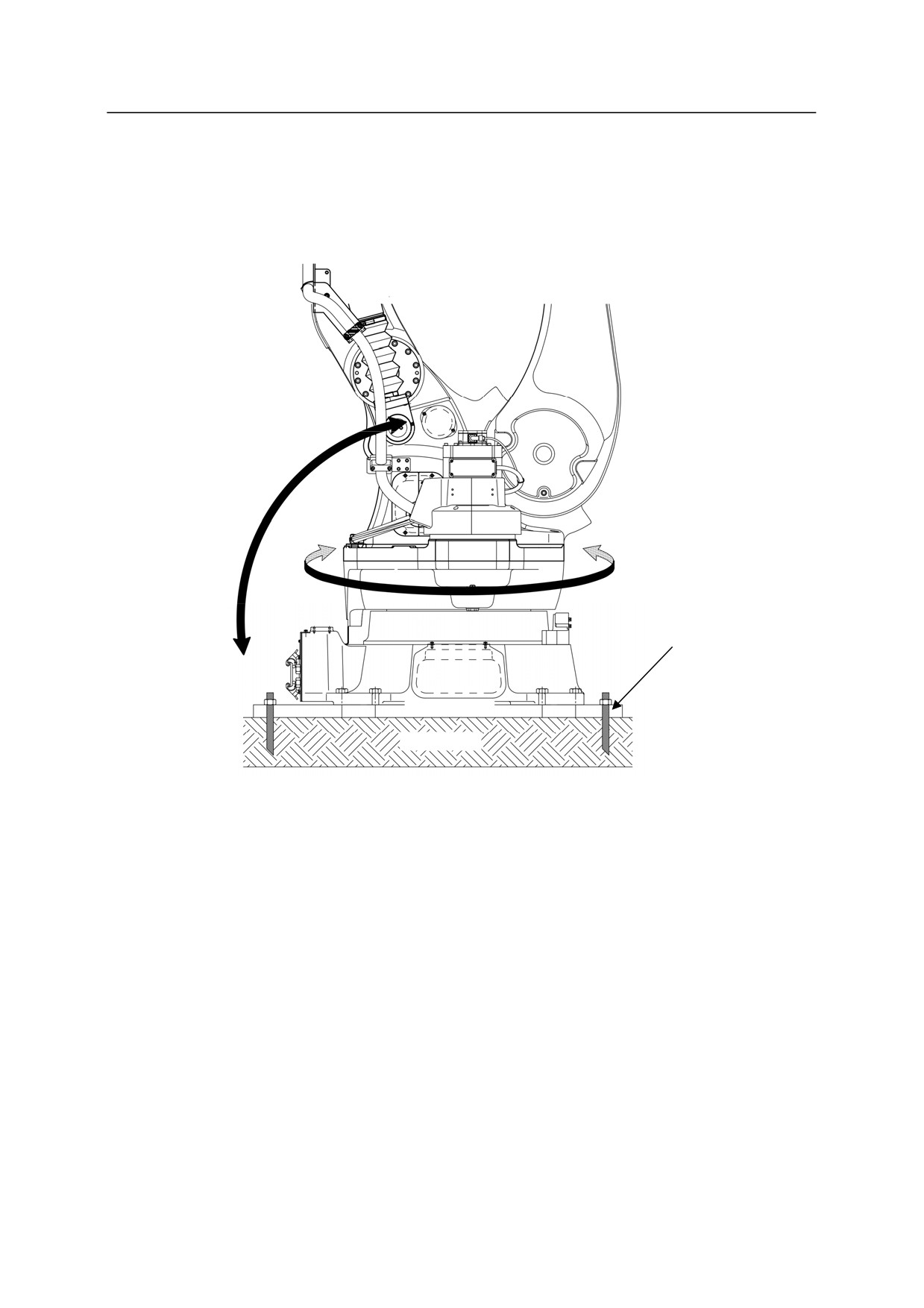
When Installing the Robot Base Plate on the Floor
In this case, install the base plate on concrete floor or steel plate using bolt holes on the base plate.
Reaction forces received from robot are the same as when installing the base directly on the floor.
M
T
Bolt hole
Base plate
Concrete
5-24
5. Installation
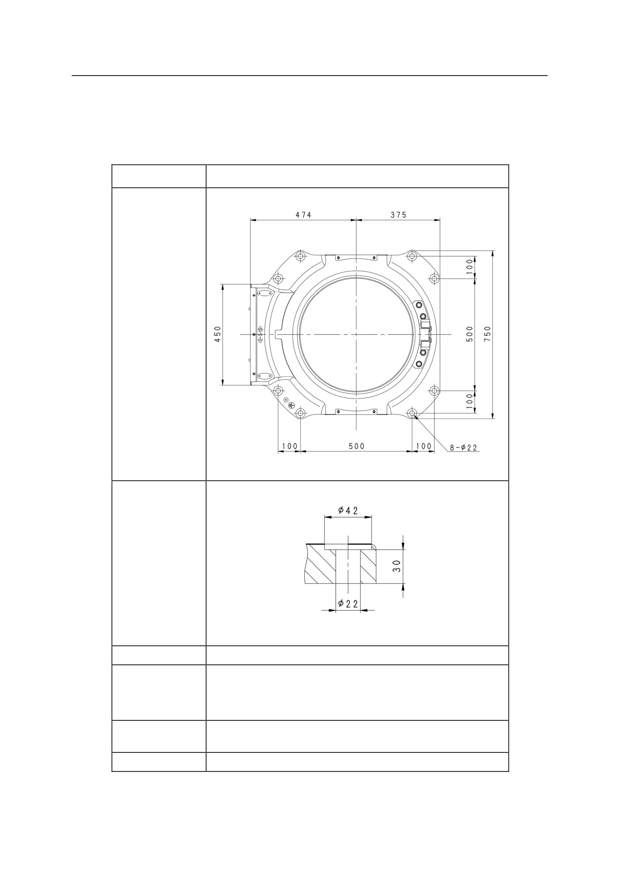
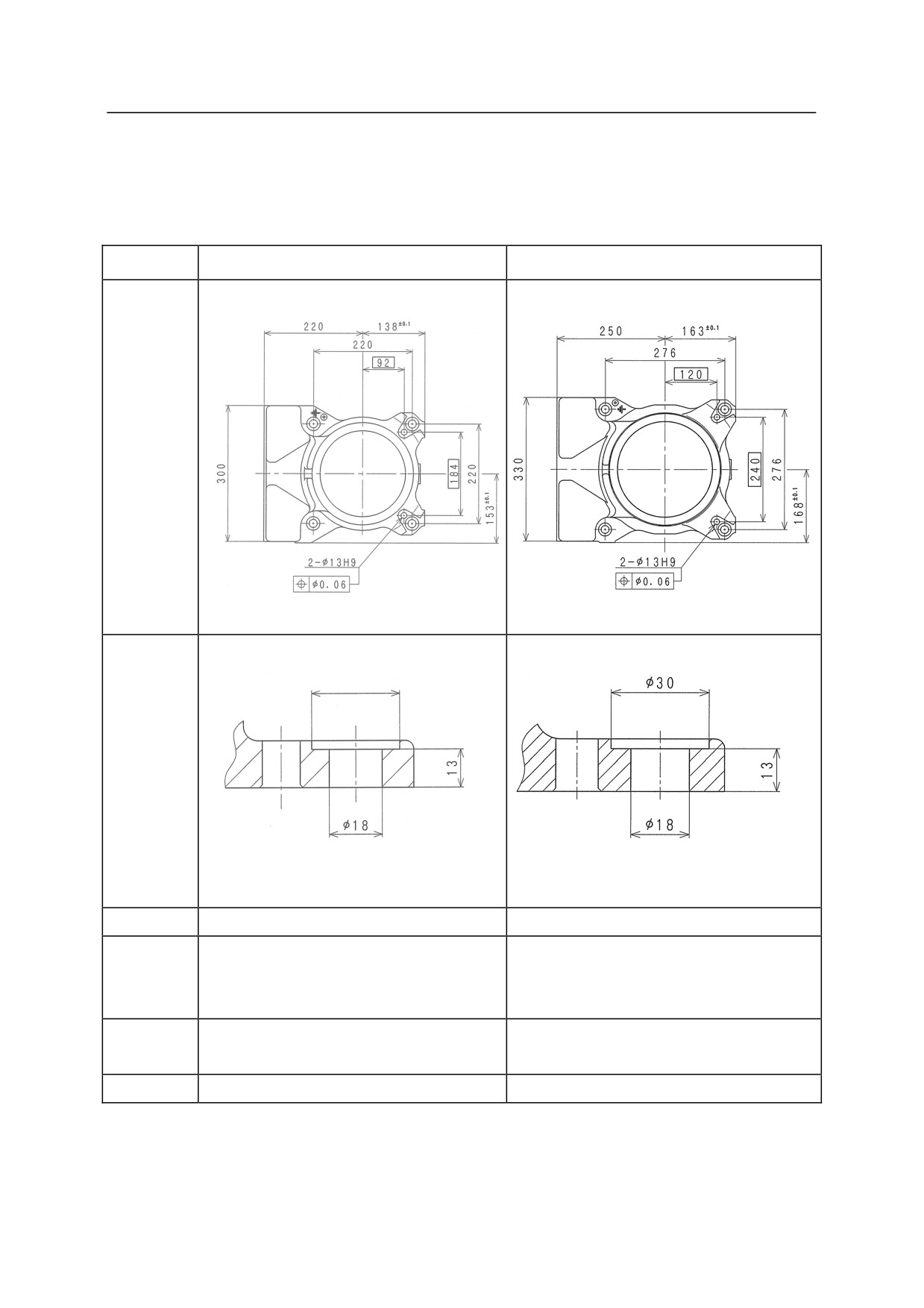
Installation Dimensions of Base Section
Fix the base section with high tension bolts through the bolt holes.
Model
CP series
Dimensions for
installation
Cross-section
of installation
section
Bolt hole
8-22
8-M20
High tension
Material: SCM435
bolt
Strength class: 10.9 min.
Tightening
431 Nm
torque
Levelness
Within 5°
5-25
5. Installation
5.3.2.4 INSTALLING M SERIES ARMS
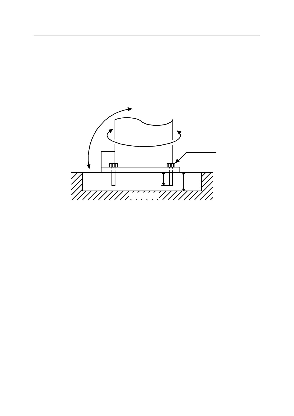
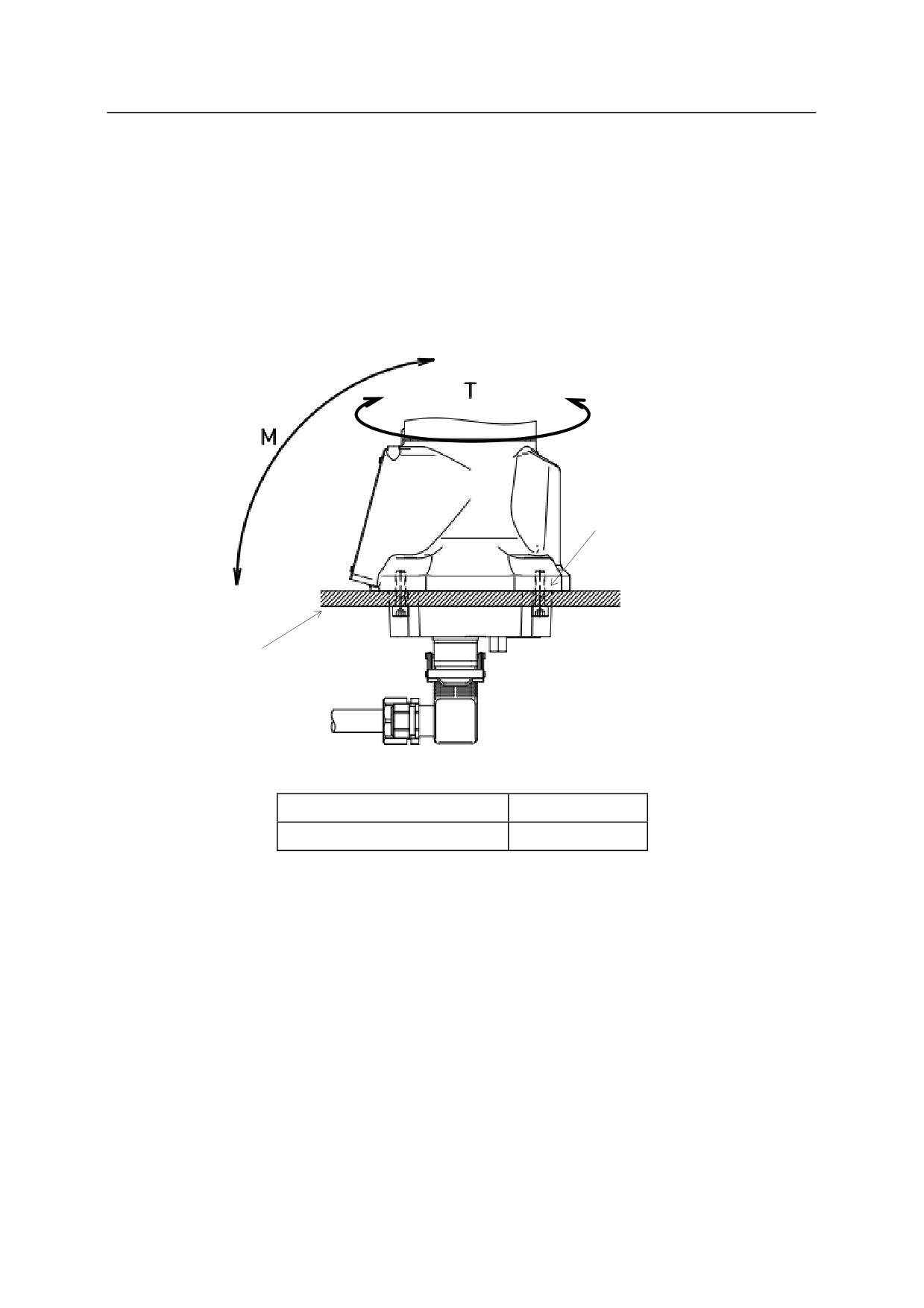
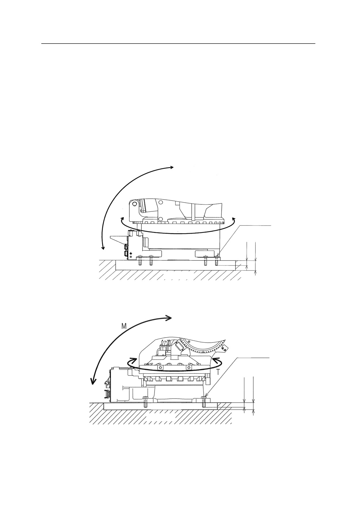
When installing the base directly on the floor:
As shown in the figure below, embed steel plate (35 mm Min. thick) in the concrete floor or fix
with anchor bolts. The steel plate must be fixed firmly so as to sustain reaction forces from the
robot.
M
T
M20
Tightening torque
431.2 N-m
30 mm
Steel
35 mm
min.
plate
min.
Concrete
When installing the base plate on the floor:
Install the base plate utilizing 8 holes of 22 diameter. Install the base plate on the concrete floor or
the steel plate floor. Reaction forces received from robot are the same as when installing the
base directly on the floor.
There are two pin holes on the base plate for positioning, which enable the base plate to join with
the base precisely. Thus, replacement of a broken robot can be done quickly and easily.
(Beware that usually JT1 is not precision zeroed. This function is only provided as Option.)
5-26
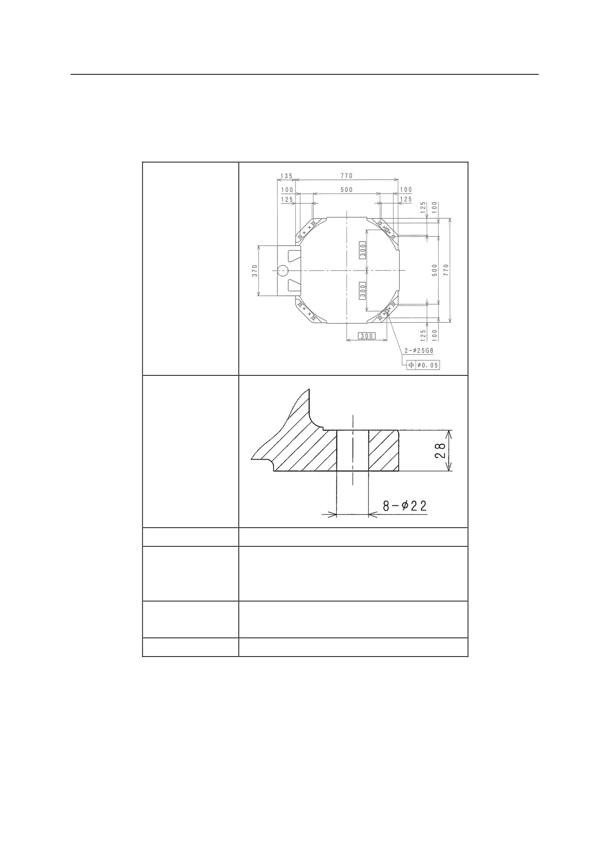
5. Installation
Installing Dimensions of Base Section
Fix the base section with high tension bolts through the bolt holes.
Installing
Dimensions of
Base Section
Cross-section of
Base installation
hole
Bolt Hole
8- 22
8-M20
High Tension
Material: SCM435
Bolt
Strength class: 10.9 min.
Tightening
431.2 N-m
Torque
Levelness
Within 5
5-27
5. Installation
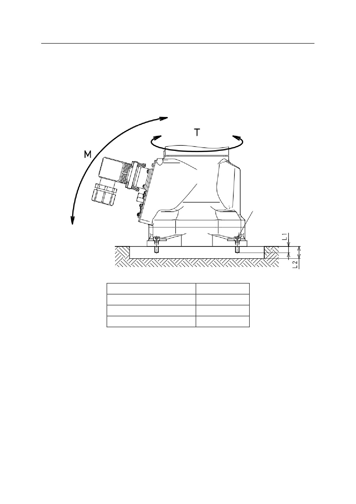
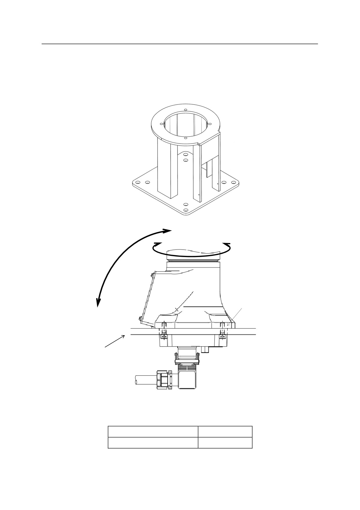
5.3.2.5 INSTALLING MC SERIES ARMS
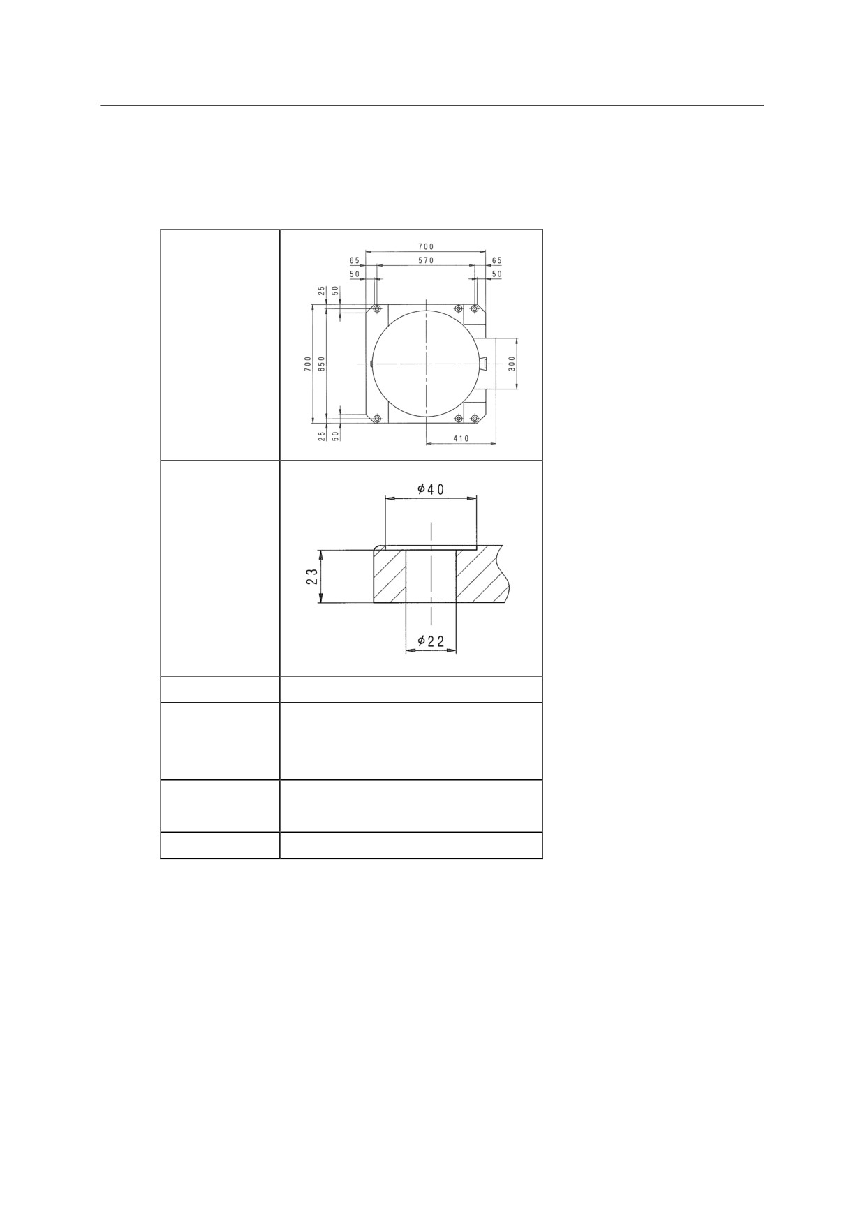
Installing Bottom Connector Specification Arm
Fix the robot on the pedestal through steel plate of thickness of 17 mm or more as shown in the
figure below. The pedestal must be fixed firmly so as to sustain reaction forces from the robot.
Robot base installation bolt
Steel plate
Robot base installation bolt
4-M10
Tightening torque
57 Nm
5-28
5. Installation
Installing Backside Connector Specification Arm
The installation method for backside connector specification arm is the same as when installing
the robot base directly on the floor.
Robot base installation bolt
Steel plate
Robot base installation bolt
4-M8
Tightening torque
29 Nm
L1
15 mm or more
L2
17 mm or more
5-29
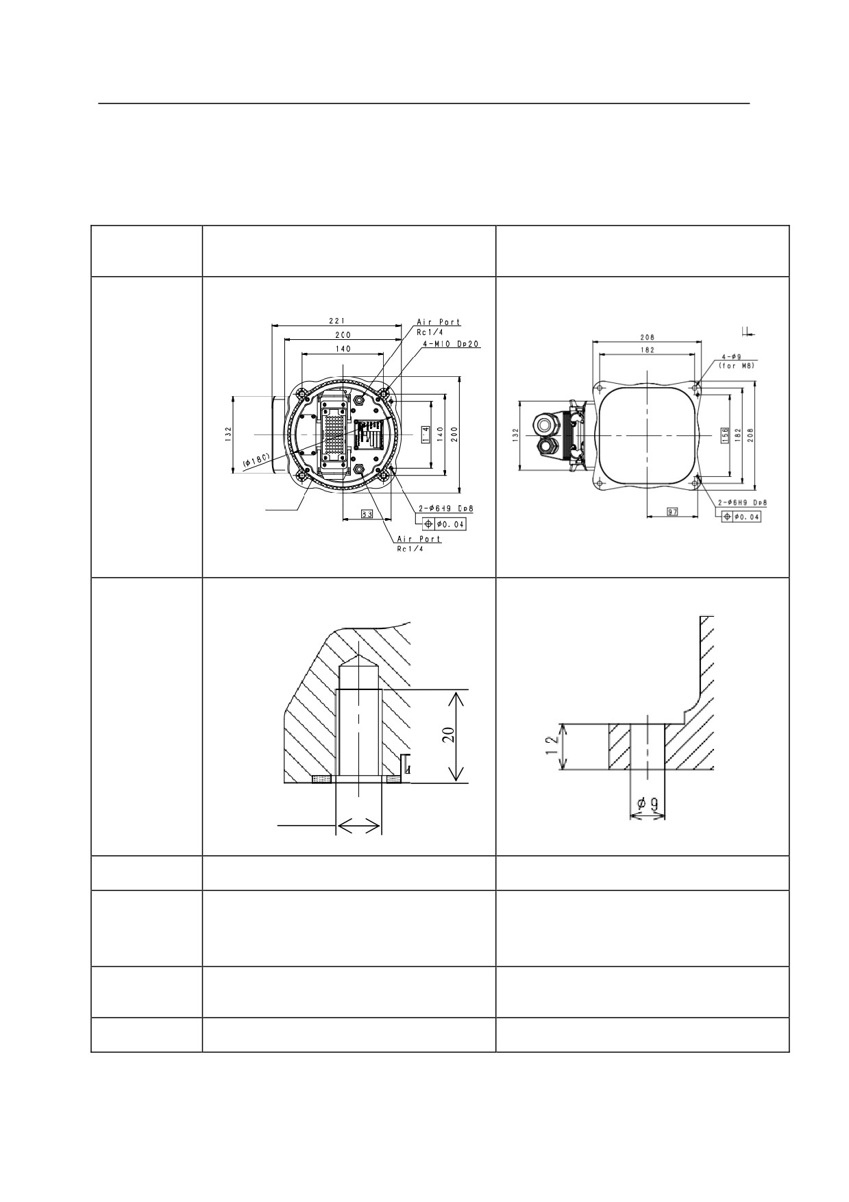
5. Installation
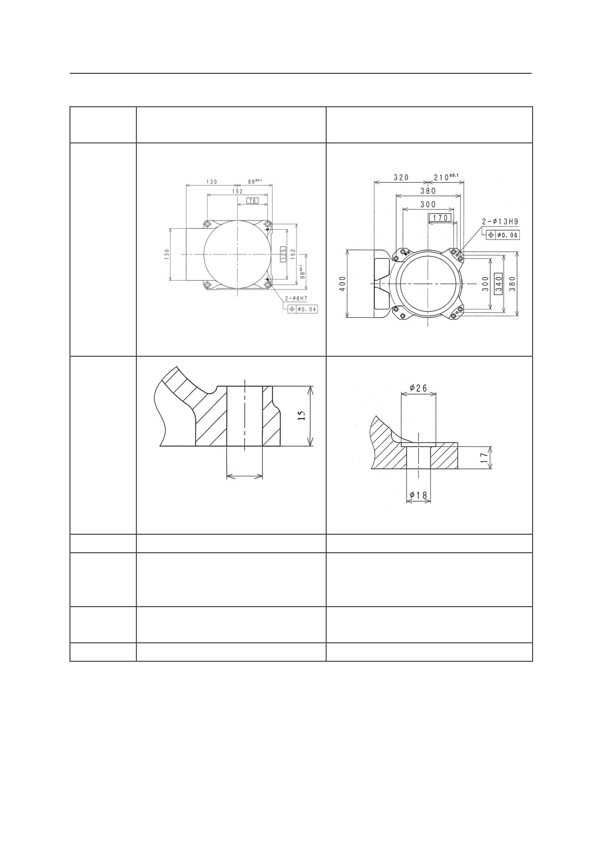
Installation Dimensions of Base Section
Fix the base section with high tension bolts through the bolt holes.
MC004N
MC004N
Model
(Bottom Connector Specification)
(Backside Connector Specification)
Dimensions
for installation
Gasket
Cross-section
of installation
section
M10
Bolt holes
䇷
4-9
4-M10
4-M8
Tightening
Material: SCM435
Material: SCM435
bolt
Strength class: 10.9 or more
Strength class: 10.9 or more
Tightening
57 N·m
29 N·m
torque
Levelness
Within 5°
Within 5°
5-30
5. Installation
5.3.2.6 INSTALLING MS SERIES ARMS
Fix the robot on the pedestal through hole (180) in steel plate of thickness of 17 mm or more as
shown in the figure below. The pedestal must be fixed firmly so as to sustain reaction forces
from the robot.
Example of pedestal
T
M
Robot base installation bolt
Steel plate
Robot base installation bolt
4-M10
Tightening torque
39 Nm
5-31
5. Installation
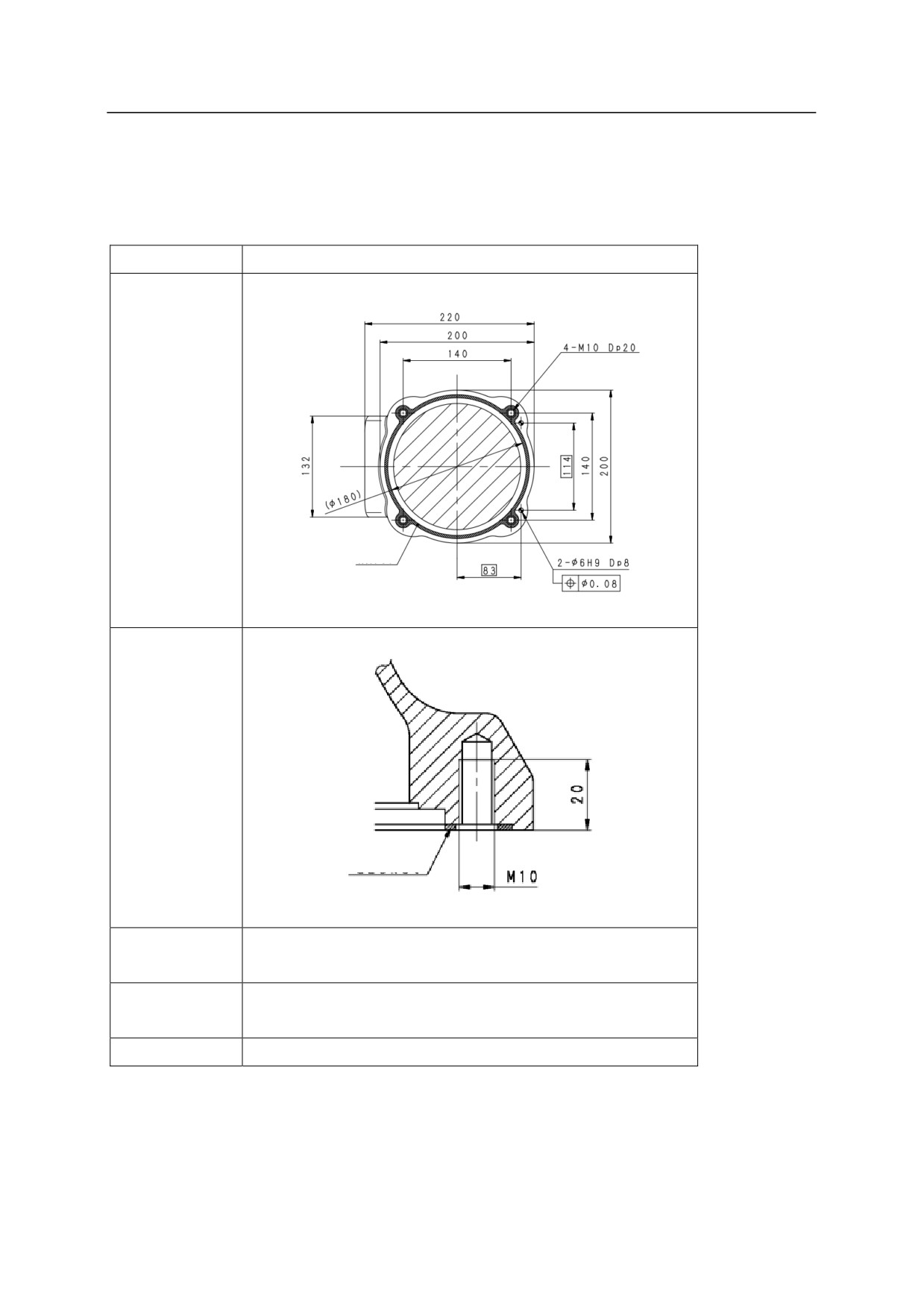
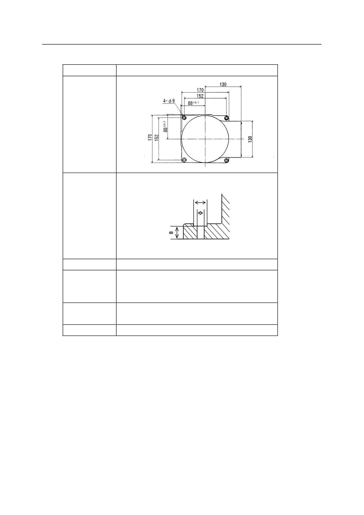
Installation Dimensions of Base Section
Fix the base section with high tension bolts through the bolt holes.
Model
MS005N
Dimensions for
installation
Gasket
Cross-section
of installation
section
Gasket
4-M10
Tightening bolt
Material: SUS304
Tightening
39 Nm
torque
Levelness
Within 5°
5-32
5. Installation
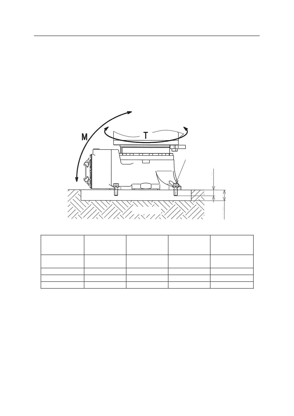
5.3.2.7 INSTALLING R SERIES ARMS
When Installing the Robot Directly on the Floor
Bury steel plate of L2 thickness (See the table below.) in the concrete floor as shown in the figure
below or fix it with anchors. The steel plate must be fixed firmly so as to sustain reaction forces
from the robot.
Robot base installation bolt
L1
Steel plate
Concrete
L2
RA10L,
RD80N, RS15X,
RA06L, RA10N,
RC05L,
Model
RA20N,
RS30N, RS50N,
RS06L, RS10N
RS05L, RS05N
RS10L, RS20N
RS80N
Robot base
4-M16
4-M16
4-M8
8-M16
installation bolt
Tightening torque
235 Nm
235 Nm
29.4 Nm
235 Nm
L1
25 mm Min.
25 mm Min.
12 mm Min.
25 mm Min.
L2
28 mm Min.
28 mm Min.
14 mm Min.
28 mm Min.
5-33
5. Installation
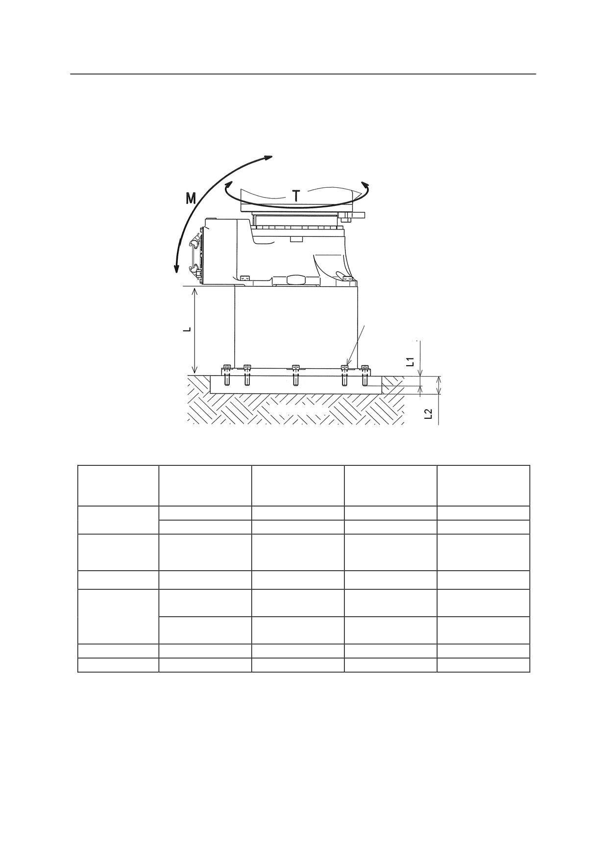
When Installing the Robot Pedestal on the Floor
In this case, the installation procedures are practically the same as the procedure shown in the
prior section.
Pedestal installation bolt
Steel
plate
Concrete
RD80N, RS15X,
RA06L, RA10N,
RA10L, RA20N,
RC05L, RS05L,
Model
RS30N, RS50N,
RS06L, RS10N
RS10L, RS20N
RS05N
RS80N
60 kg (L=600)
70 kg (L=600)
24 kg (L=600)
100 kg (L=600)
Pedestal mass
35 kg (L=300)
45 kg (L=300)
17 kg (L=300)
65 kg (L=300)
Pedestal
8-M12
8-M12
8-M10
8-M16
installation bolt
Tightening torque
98 Nm
98 Nm
56.8 Nm
235 Nm
600
600
600
600
(60360-1164*)
(60360-1166*)
(60360-0082*)
(60360-1178*)
L
300
300
300
300
(60360-1165*)
(60360-1167*)
(60360-0203*)
(60360-1179*)
L1
18 mm Min.
18 mm Min.
15 mm Min.
25 mm Min.
L2
20 mm Min.
20 mm Min.
17 mm Min.
28 mm Min.
NOTE* (
) indicates the part number of pedestal.
5-34
5. Installation
When Installing the Robot Base Plate on the Floor
In this case, install the base plate on concrete floor or steel plate using bolt holes on the base plate.
Bolt hole
Base plate
Concrete
RD80N, RS15X,
RA06L, RA10N,
RA10L, RA20N,
RC05L, RS05L,
Model
RS30N, RS50N,
RS06L, RS10N
RS10L, RS20N,
RS05N
RS80N
Base plate mass
110 kg
110 kg
20 kg
110 kg
Base plate
4-20
4-20
4-14
4-26
installation hole
(PCD800)
(PCD800)
(300 300)
(PCD800)
Base plate
dimension
750 750 25
750 750 25
400 400 16
750 750 25
(mm)
5-35
5. Installation
Installation Dimensions of Base Section
Fix the base section with high tension bolts through the bolt holes.
Model
RA06L, RA10N, RS06L, RS10N
RA10L, RA20N, RS10L, RS20N
Dimensions
for
installation
䃥30
Cross-
section
of
installation
section
Bolt hole
4- 18
4- 18
High
4-M16
4-M16
tension
Material: SCM435
Material: SCM435
bolt
Strength class: 10.9 min.
Strength class: 10.9 min.
Tightening
235 N-m
235 N-m
torque
Levelness
Within 5°
Within 5°
5-36
5. Installation
RD80N, RS15X, RS30N, RS50N,
Model
RC05L, RS05N, RS05L
RS80N,
Dimensions
for
installation
Cross-section
of installation
section
9
Bolt hole
4-9
8-18
4-M8
8-M16
High tension
Material: SCM435
Material: SCM435
bolt
Strength class: 10.9 min.
Strength class: 10.9 min.
Tightening
29.4 Nm
235 Nm
torque
Levelness
Within 5°
Within 5°
5-37
5. Installation
Model
RS03N
Dimensions for
installation
φ14
Cross-section
φ9
of installation
section
Bolt hole
4-9
4-M8
High tension
Material: SCM435
bolt
Strength class: 10.9 min
Tightening
29.4 Nm
torque
Levelness
Within 5°
5-38
5. Installation
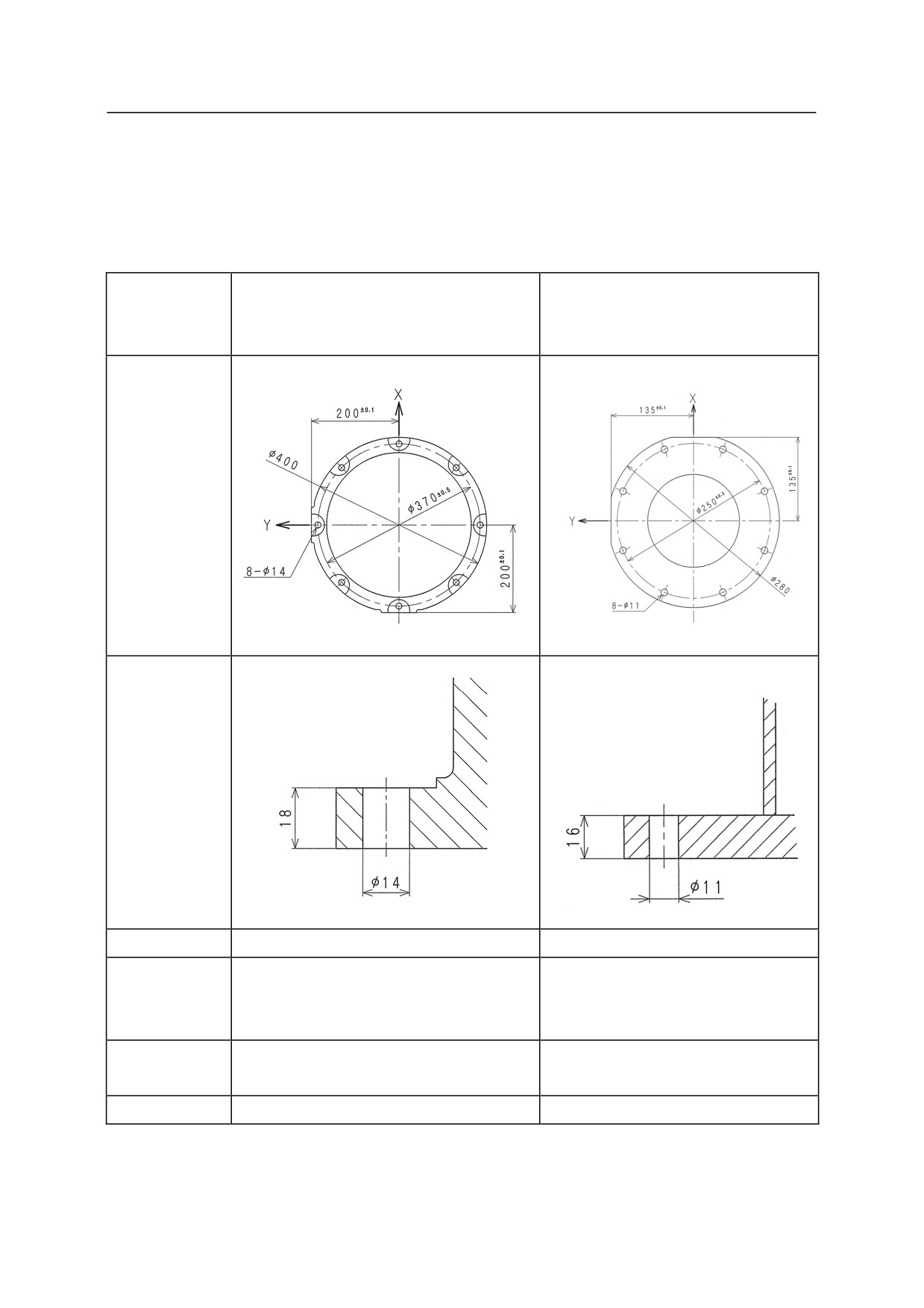
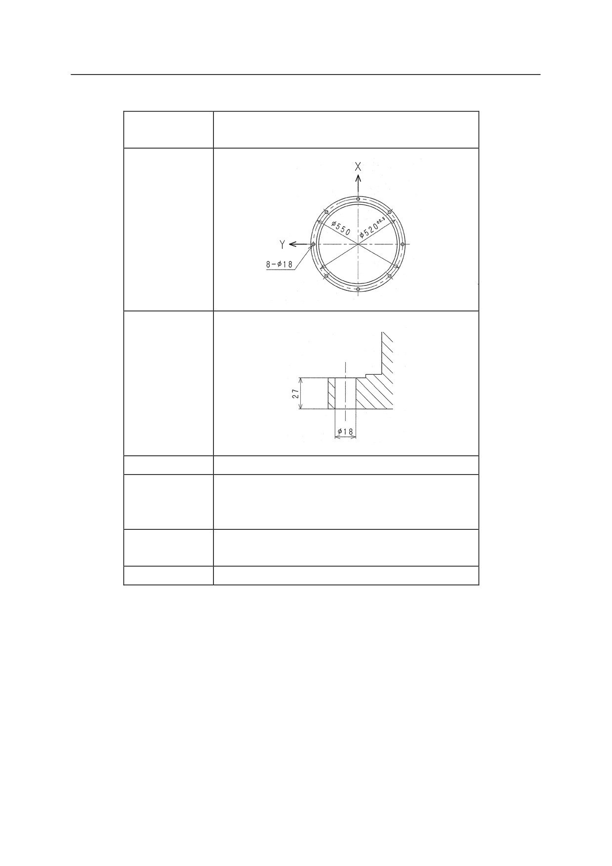
Installation Dimensions of Robot Pedestal
When installing a robot on the pedestal, fix the pedestal with high tension bolts through the bolt
holes.
RA06L, RA10L, RA10N,
Model
RA20N, RS06L, RS10L,
RC05L, RS05L, RS05N
RS10N, RS20N
Dimensions
for
installation
Cross-section
of installation
section
Bolt hole
8-14
8-11
8-M12
8-M10
High tension
Material: SCM435
Material: SCM435
bolt
Strength class: 10.9 min
Strength class: 10.9 min
Tightening
98 Nm
56.8 Nm
torque
Levelness
Within 5°
Within 5°
5-39
5. Installation
RD80N, RS15X, RS30N,
Model
RS50N, RS80N
Dimensions for
installation
Cross-section
of installation
section
Bolt hole
8-18
8-M16
High tension
Material: SCM435
bolt
Strength class: 10.9 min
Tightening
235 Nm
torque
Levelness
Within 5°
5-40
5. Installation
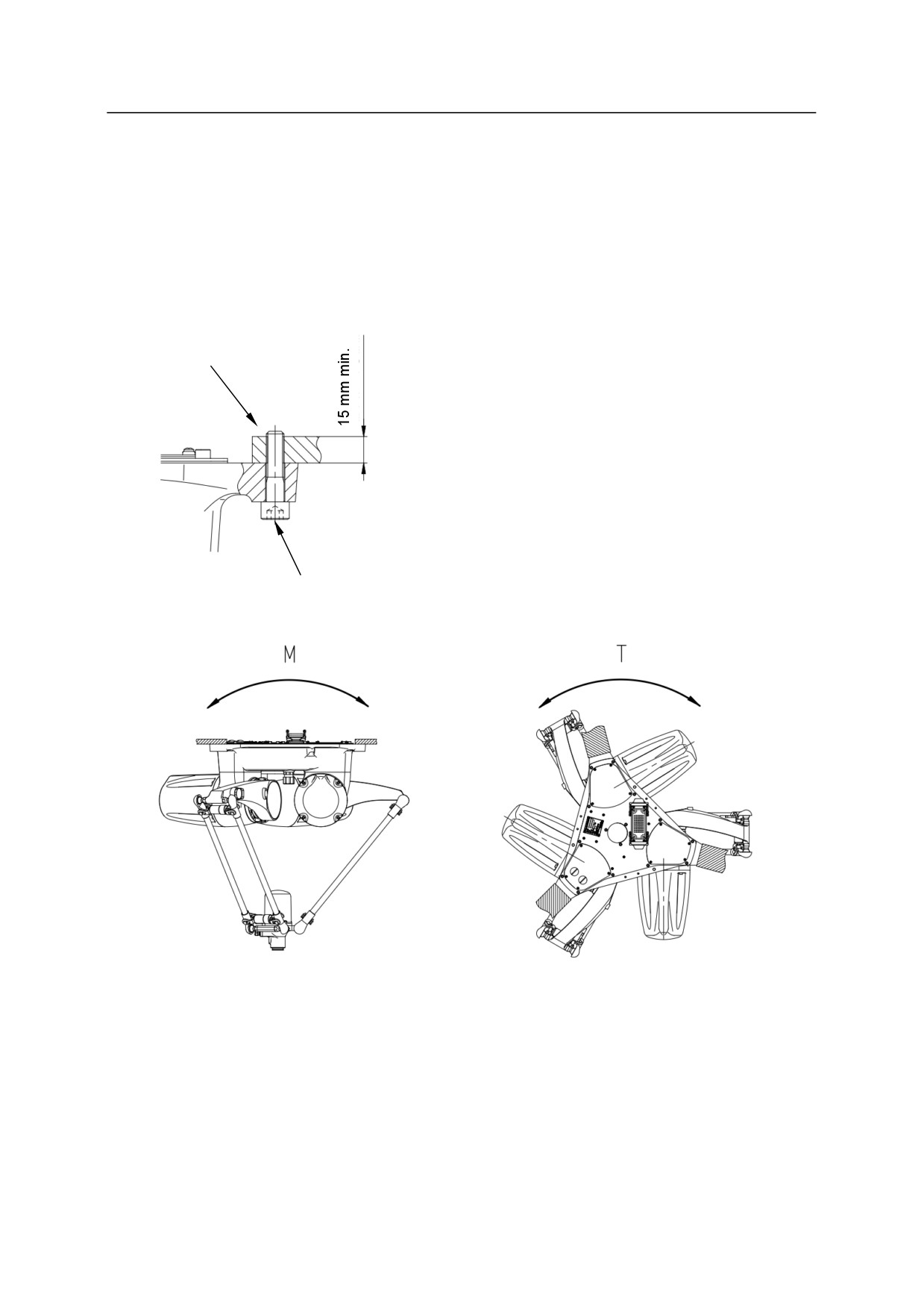
5.3.2.8 INSTALLING Y SERIES ARMS
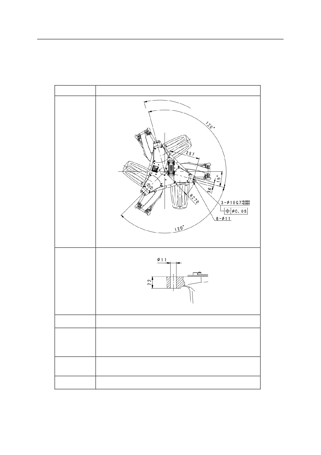
YF002N
As in the figure below, embed steel plate (15 mm or more) on the stand whose natural frequency
is 30 Hz or more. The steel plate must be fixed firmly so as to sustain reaction forces from the
robot.
Steel plate
6-M10
Tightening torque: 39.0 Nm
5-41
5. Installation
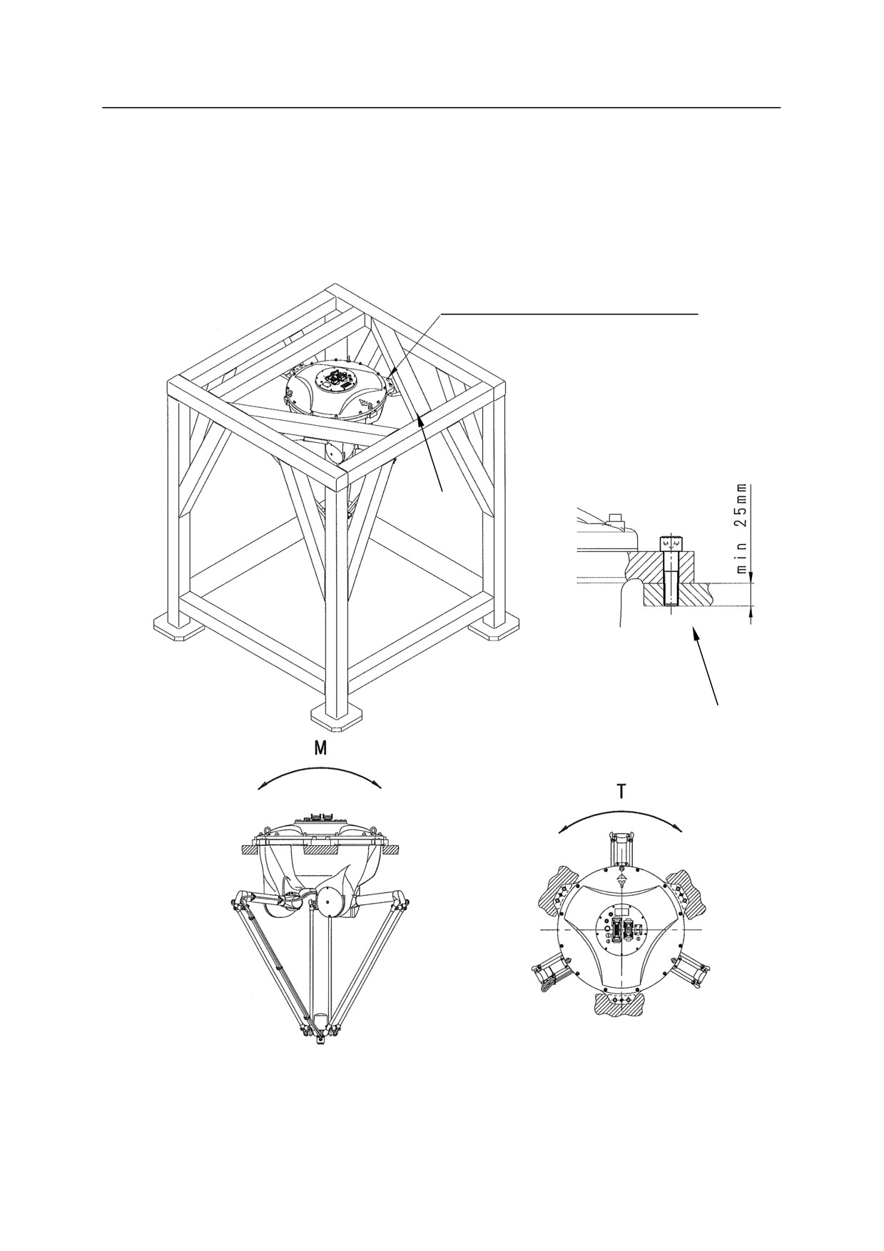
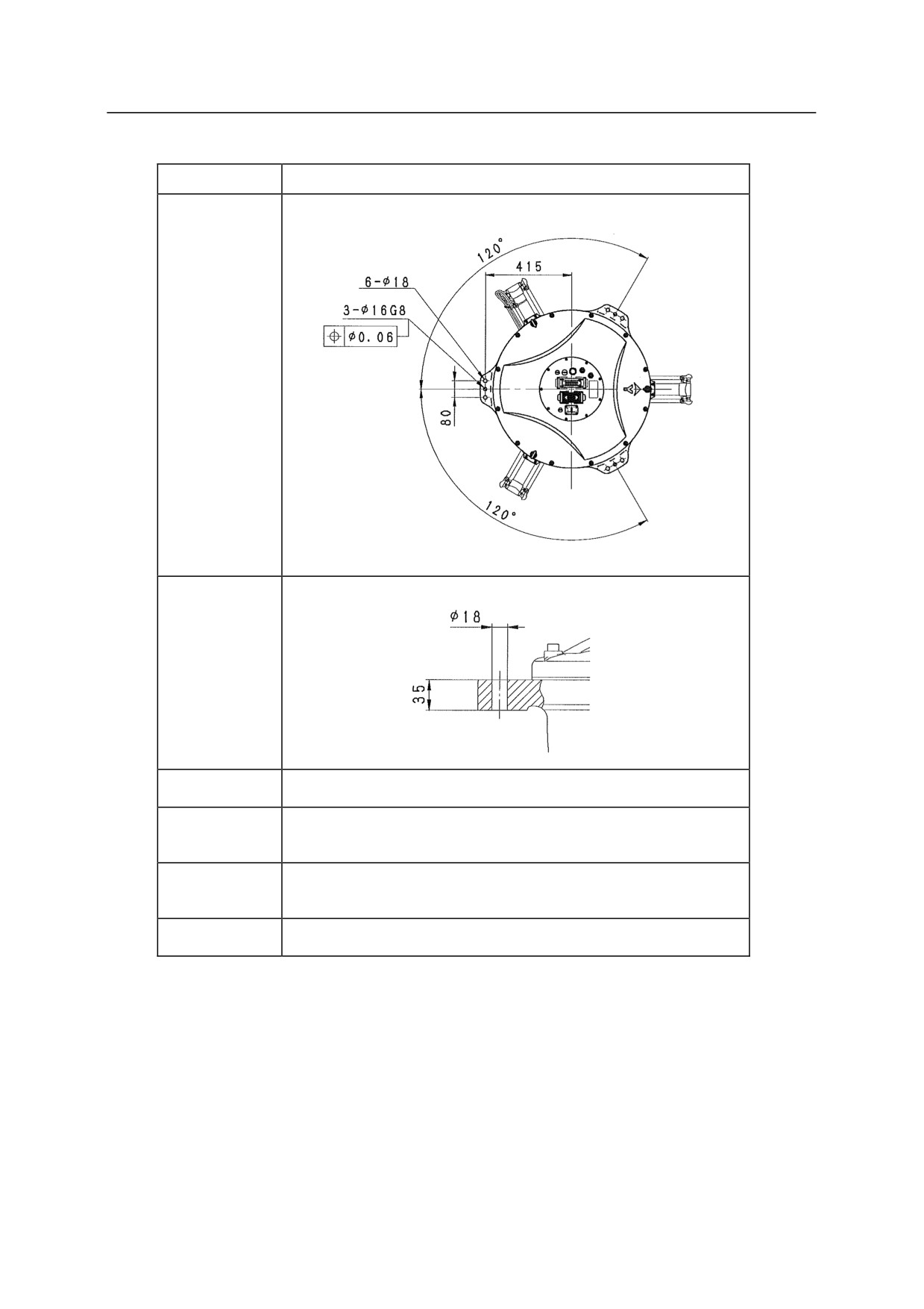
YF003N
Fix the robot arm to a pedestal as shown in the figure below. The arm should be fixed on to
steel plate (25 mm min. thickness) and the pedestal should be rigid with natural frequency of 30
Hz or more. Secure the pedestal strongly enough to endure the reaction forces produced by the
robot arm.
6-M16
Tightening torque: 164.5 N-m
Steel plate
Steel plate
5-42
5. Installation
Installation Dimensions of Base Section
Fix the base section with high tension bolts through the bolt holes.
Model
YF002N
Dimensions
for installation
Cross-section
of installation
section
Bolt hole
6-18
6-M10
Bolt
Material: SUS304
Strength class: A2-70
Tightening
39.0 N-m
torque
Levelness
Within 㼼5㼻
5-43
5. Installation
Model
YF003N
Dimensions for
installation
Cross-section
of installation
section
Bolt hole
6-18
6-M16
Bolt
Material: SUS304
Tightening
164.5 N-m
torque
Levelness
Within 5°
5-44
5. Installation
5.3.2.9 INSTALLING Z SERIES ARMS
ZB Series
When Installing the Base Directly on the Floor
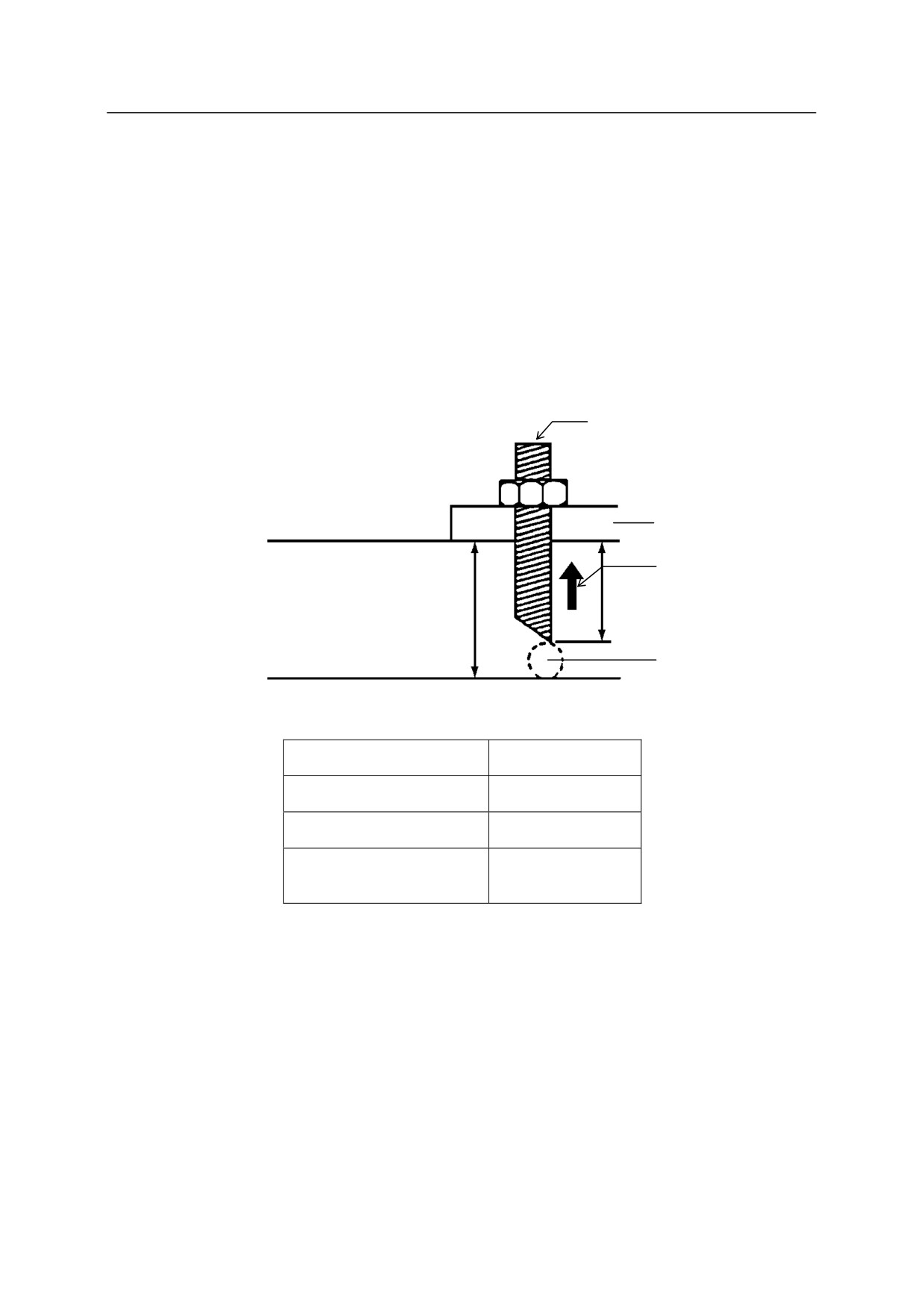
When the robot base is installed directly on the concrete floor, use chemical anchor bolts as a
standard. Metal anchor bolts can be used as an alternative for the chemical anchor bolts.
Chemical anchor
Base
Max. pull-out load
Length of engagement
Concrete thickness
Unable to drill through
Chemical anchor
M20
Length of engagement
200 mm or more
Concrete thickness
230 mm or more
Max. pull-out load
127400 N
(includes bolt tightening)
5-45
5. Installation
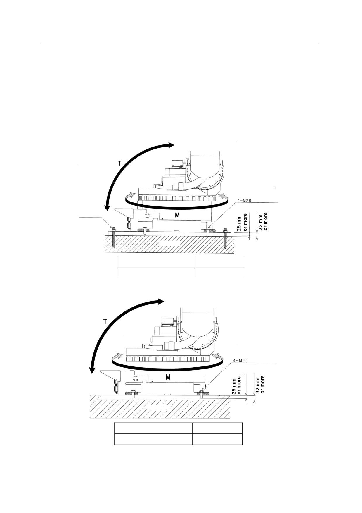
When Installing a Plate between the Robot and the Floor
Fix the steel plate (32 mm Min. thick) onto the floor using anchor bolts or embed it into the
concrete, and fix the robot base onto the steel plate using high-tension bolts. The base plate
must be fixed as firmly as possible to withstand the reaction forces it receives from the robot
during operation.
Fixing the steel plate using anchor bolts
Tightening torque: 431.2 Nm
Anchor bolt
Steel plate
Concrete
High tension bolt
4-M20
Length of engagement
25 mm or more
Fixing the steel plate embedded into concrete
Tightening torque: 431.2 Nm
Steel plate
Concrete
High tension bolt
4-M20
Length of engagement
25 mm or more
5-46
5. Installation
Installation Dimensions of Base Section
Fix the base section with high tension bolts through the bolt holes.
Dimensions for
installation
Cross-section
of Installation
Bolt hole
4 - 22
4-M20
High tension
Material: SCM435
bolt
Strength class: 10.9 or more
Tightening
431.2 N-m
torque
Levelness
Within 5
5-47
5. Installation
ZD/ZH/ZT/ZX Series
When installing the base directly on the floor:
As shown in the figure below, embed steel plate (35 mm Min. thick) in the concrete floor or fix
with anchor bolts. The steel plate must be fixed firmly so as to sustain reaction forces from the
robot.
ZD/ZT/ZX Series
M
M20
T
Tightening torque
431.2 N-m
30 mm
35 mm
min.
min.
Steel plate
Concrete
ZH Series
M20
Tightening torque
431.2 N-m
30 mm
35 mm
min.
min.
Steel plate
Concrete
5-48
5. Installation
When installing the base plate with positioning holes on the floor:
Install the base plate utilizing 8 holes of 22 in diameter.
(4 holes for ZH series) Install the base
plate on the concrete floor or the steel plate floor. Reaction forces received from robot are the
same as when installing the base directly on the floor.
There are two pin holes on the base plate for positioning, which enable the base plate to join with
the base precisely. Thus, replacement of a broken robot can be done quickly and easily.
(Beware that usually JT1 is not precision zeroed. This function is only provided as Option.)
5-49
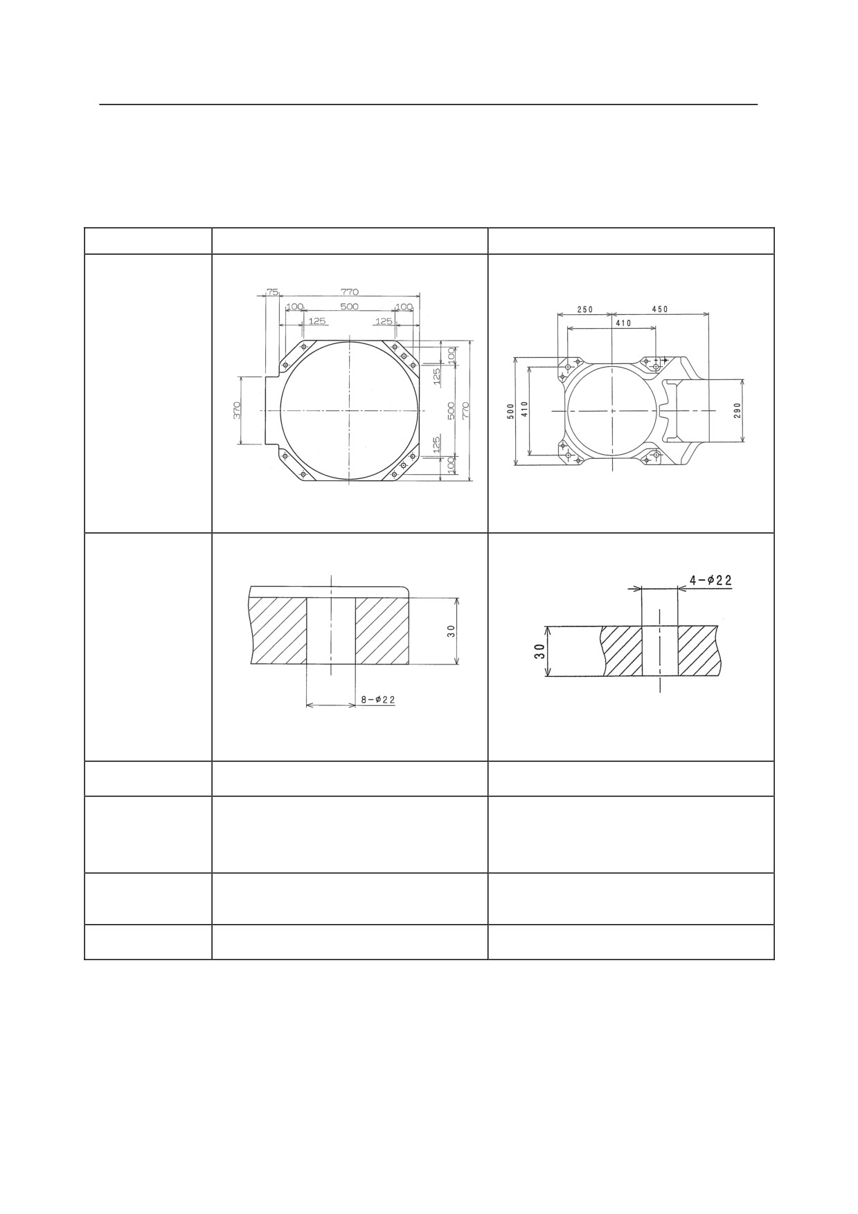
5. Installation
Installing Dimensions of Base Section
Fix the base section with high tension bolts through the bolt holes.
ZD/ZT/ZX series
ZH series
Dimensions for
installation
Cross-section
of installation
section
Bolt hole
8-22
4-22
8-M20
4-M20
High tension
Material: SCM435
Material: SCM435
bolt
Strength class: 10.9 min.
Strength class: 10.9 min.
Tightening
431.2 N-m
431.2 N-m
torque
Levelness
Within 5
Within 5
5-50
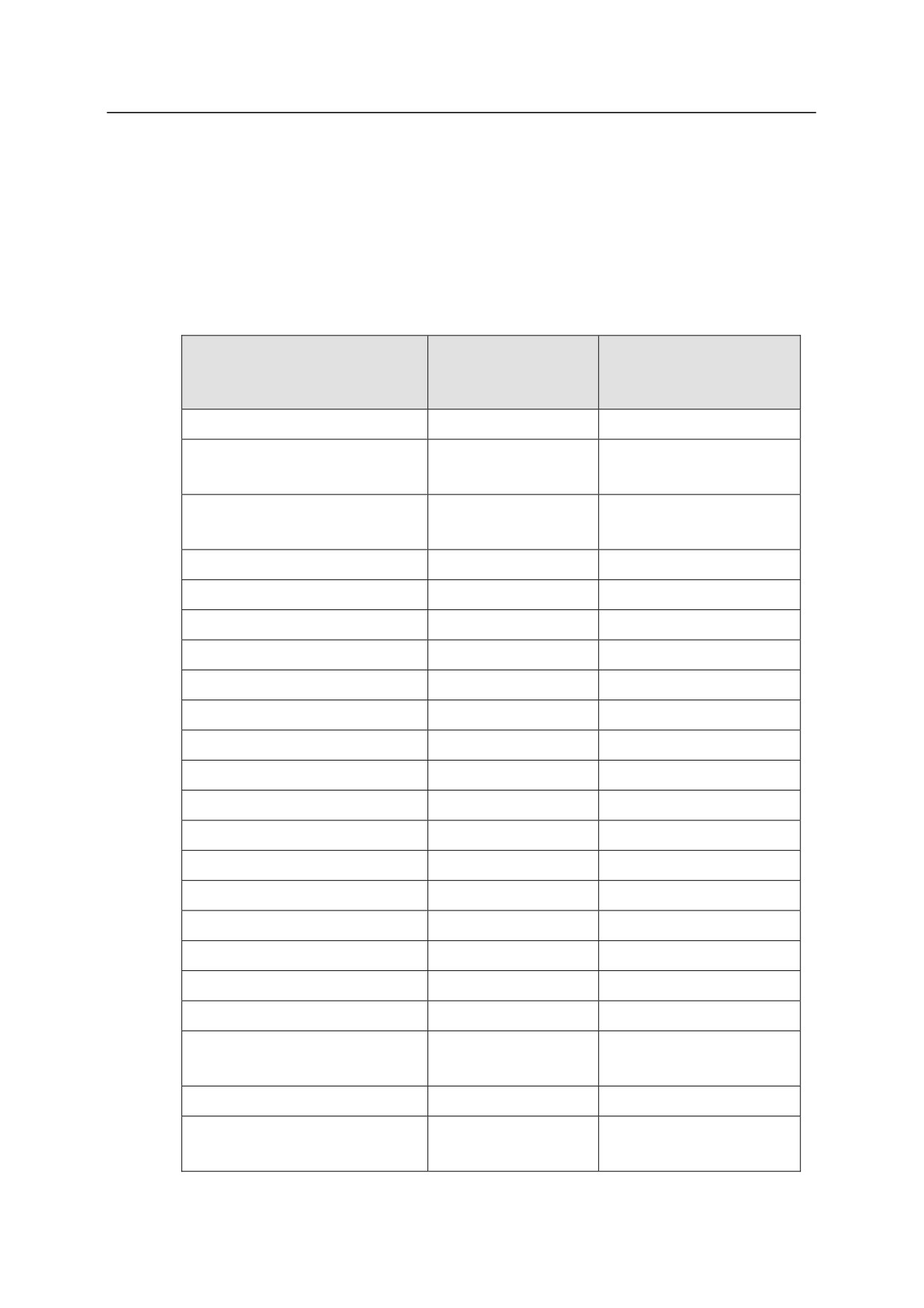
5. Installation
5.3.3 MOVEMENT REACTION ACTING ON INSTALLATION SURFACE DURING
OPERATION
Refer to the list below for the movement reaction that acts on the installation surface during
normal operation. Consider these values at when installing robot arms as shown in the previous
pages.
T
M
Model
(Rotating Torque)
(Inversion Moment)
BA006N
1935 N-m
2527 N-m
BT165L
21700 N-m
40400 N-m
BT200L
BX100L/BX130X
15000 N-m
35000 N-m
BX165L/BX200L
BX100N
10000 N-m
31000 N-m
BX100S
10000 N-m
27000 N-m
BX165N
13000 N-m
33400 N-m
BX250L/BX300L
17000 N-m
50000 N-m
CP180L
28000 N-m
40000 N-m
CP300L
28000 N-m
50000 N-m
CP500L
28000 N-m
60000 N-m
MC004N
378 N-m
490 N-m
MD400N
11500 N-m
44500 N-m
MD500N
14000 N-m
37000 N-m
MS005N
430 N-m
810 N-m
MT400N
18500 N-m
46500 N-m
MX350L
13500 N-m
40000 N-m
MX420L
14500 N-m
43500 N-m
MX500N/MX700N
15500 N-m
48000 N-m
RA06L/RA10N/RS06L/RS10N
2168 N-m
3223 N-m
RA10L/RA20N
5614 N-m
6300 N-m
RS10L/RS20N
RC05L/RS05L/RS05N
849 N-m
1127 N-m
RD80N/RS15X/RS30N
12101 N-m
15937 N-m
RS50N/RS80N
5-51

5. Installation
T
M
Model
(Rotating Torque)
(Inversion Moment)
RS03N
293 N-m
357 N-m
YF002N
200 N-m
400 N-m
YF003N
500 N-m
700 N-m
ZB150S
9000 N-m
24000 N-m
ZD series
10000 N-m
26000 N-m
ZH100U
9000 N-m
22000 N-m
ZT series
12000 N-m
35000 N-m
ZX series
12000 N-m
34000 N-m
(Excluding ZX300S)
ZX 300S
12000 N-m
41000 N-m
5-52
5. Installation
5.4 MOUNTING OF TOOL
At the end of the robot arm, a flange is provided for mounting a tool. To mount a tool, tighten
the mounting bolts into the tapped holes machined on circumference of the flange surface.
Position the tool utilizing the pin holes and positioning hole or boss. Select the length of
mounting bolts according to the depth of tap in arm side and thickness of tool parts so that the
specified screwing engagement can be attained. Use high tension mounting bolts and tighten
them to the specified torque. Refer to the following sections for specifications of the flange,
mounting bolts, etc. for each robot arm.
㸟
WARNING
Prior to mounting tools on the robot arm, turn OFF the controller power
switch and the external power switch. Display signs indicating clearly
“Installation and connection in progress”, and lockout/ tagout the external
power switch to prevent personnel from accidentally turning ON the power.
㸟
CAUTION
If the engagement length has exceeded the specified value, the mounting
bolt might bottom out, and the tool will not be fixed securely.
5-53
5. Installation
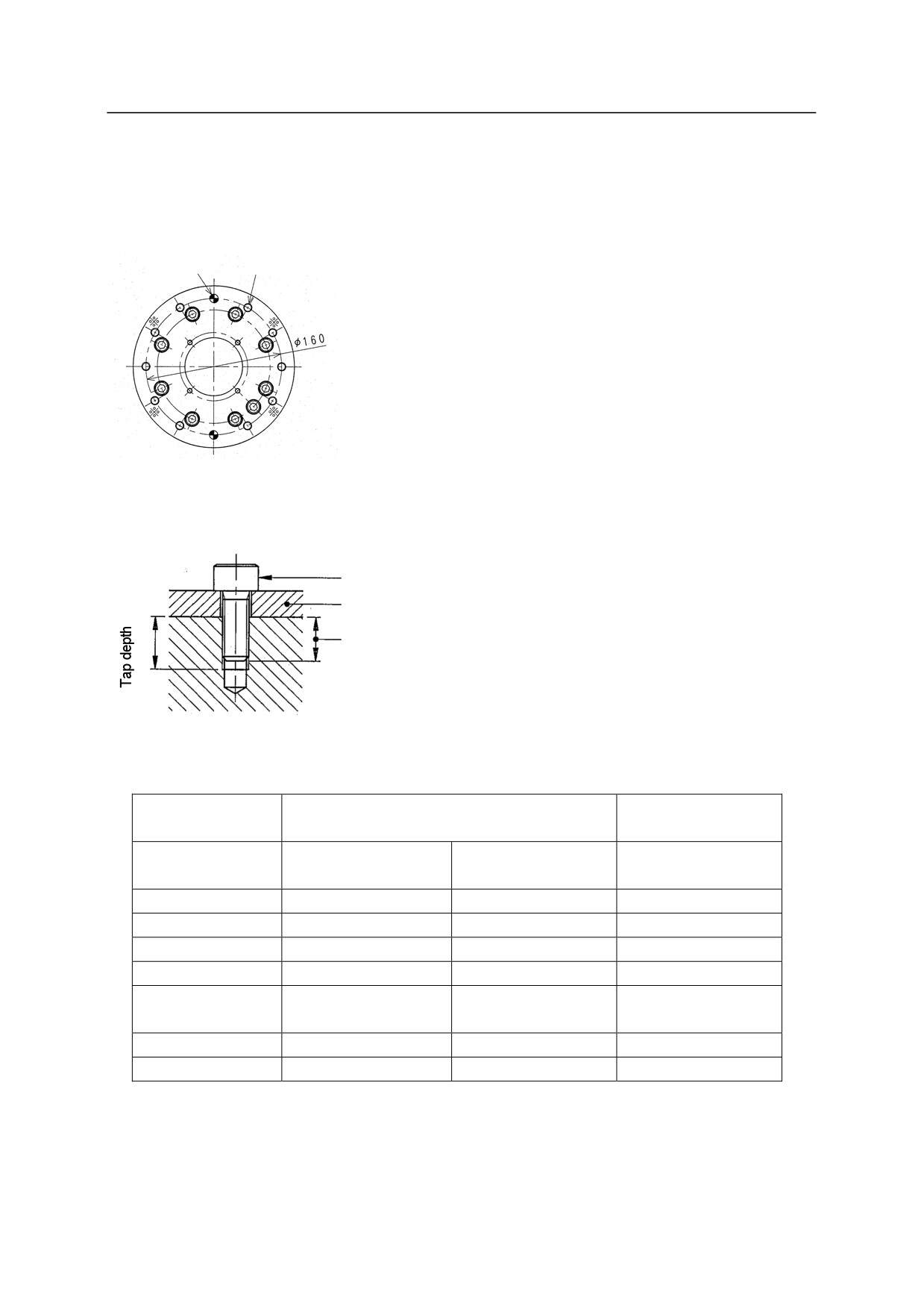
5.4.1 MOUNTING TOOL TO B SERIES ARM
Dimensions of Wrist End
Pin hole
Tapped holes
Specification of Mounting Bolts
Mounting bolt
Tool
Length of
engagement
Optional flange
Standard flange
(Adaptor plate)
B series (except
B series (except
Model
BX250L/300L
BX250L/300L)
BX250L/300L)
Tapped holes
6-M10
10-M10
6-M10
D
160
160
125
Pin hole
2-10H7 Depth 12
2-10H7 Depth 12
2-10H7 Depth 14
Tap depth
19 mm
13 mm (through)
20 mm
Length of
13 - 14 mm
13 - 18mm
13 - 14 mm
engagement
High tension bolt
SCM435, 10.9 min
SCM435, 10.9 min
SCM435, 10.9 min
Tightening torque
56.84 Nm
56.84 Nm
56.84 Nm
5-54
5. Installation
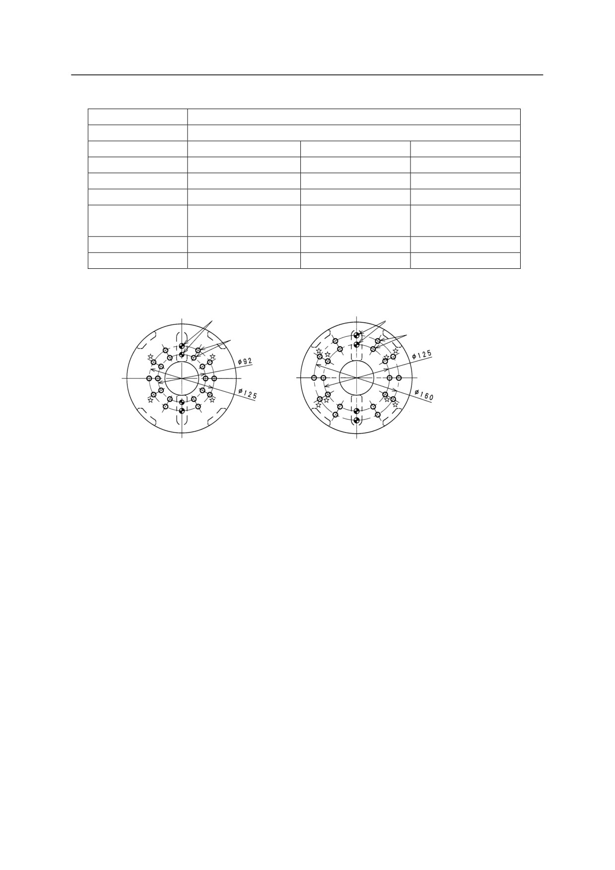
Optional flange (Adaptor bracket)
Model
B series (except BX250L/300L)
Tapped holes
10-M10
6-M10*
6-M10*
D
92
125
160
Pin hole
2-9H7 Depth 12
2-10H7 Depth 12
2-10H7 Depth 12
Tap depth
12 mm (through)
12 mm (through)
12 mm (through)
Length of
13 - 18 mm
13 - 18 mm
13 - 18 mm
engagement
High tension bolt
SCM435, 10.9 min
SCM435, 10.9 min
SCM435, 10.9 min
Tightening torque
56.84 Nm
56.84 Nm
56.84 Nm
NOTE* No need to use the tapped holes with ۼ in the figures below.
Pin hole
Pin hole
Tapped hole
Tapped hole
5-55