Kawasaki Robot (B, BA, CP, CX, M, MC, MS, R, Y, Z). Instruction Manual (2015) - page 8
6. Connection
E70/E71/E91 controllers
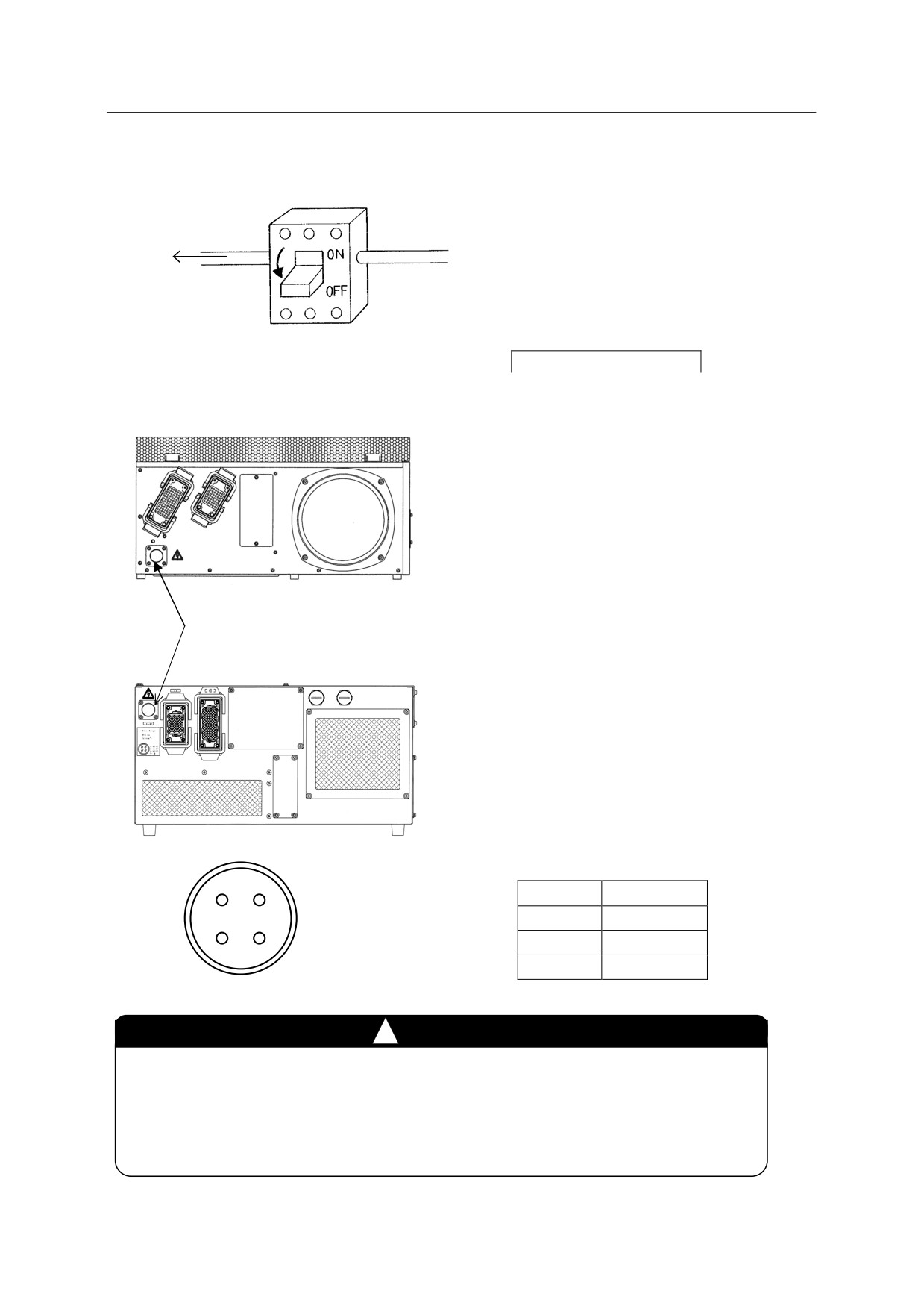
Connect the external power according to the
following procedure.
1. Turn OFF the external power for the
Connect with the
controller.
external power
circuit breaker at
㻌the installation
2. Set
CONTROLLER POWER switch on the
site.
front of the controller to the OFF position
E70/E71 controllers
without fail.
3. Feed the external power cable into the inlet
on the rear of the controller.
y Solder the attached connector on the external
power cable. The figure below shows pin
External power connector
configuration of connector.
E91 controller
D A
A
AC(L)
C B
B
(N.C.)
C
AC(N)
D
FG
Wiring diagram of attached connector
!
CAUTION
1. Confirm current requirements and select a power cable with adequate
capacity.
2. Do not install wire that is too small in diameter, the voltage may drop or the
cable may overheat.
6-21
6. Connection
6-22
7. Switches on the Robot Controller
7.0 SWITCHES ON THE ROBOT CONTROLLER
7.1 OPERATION PANEL
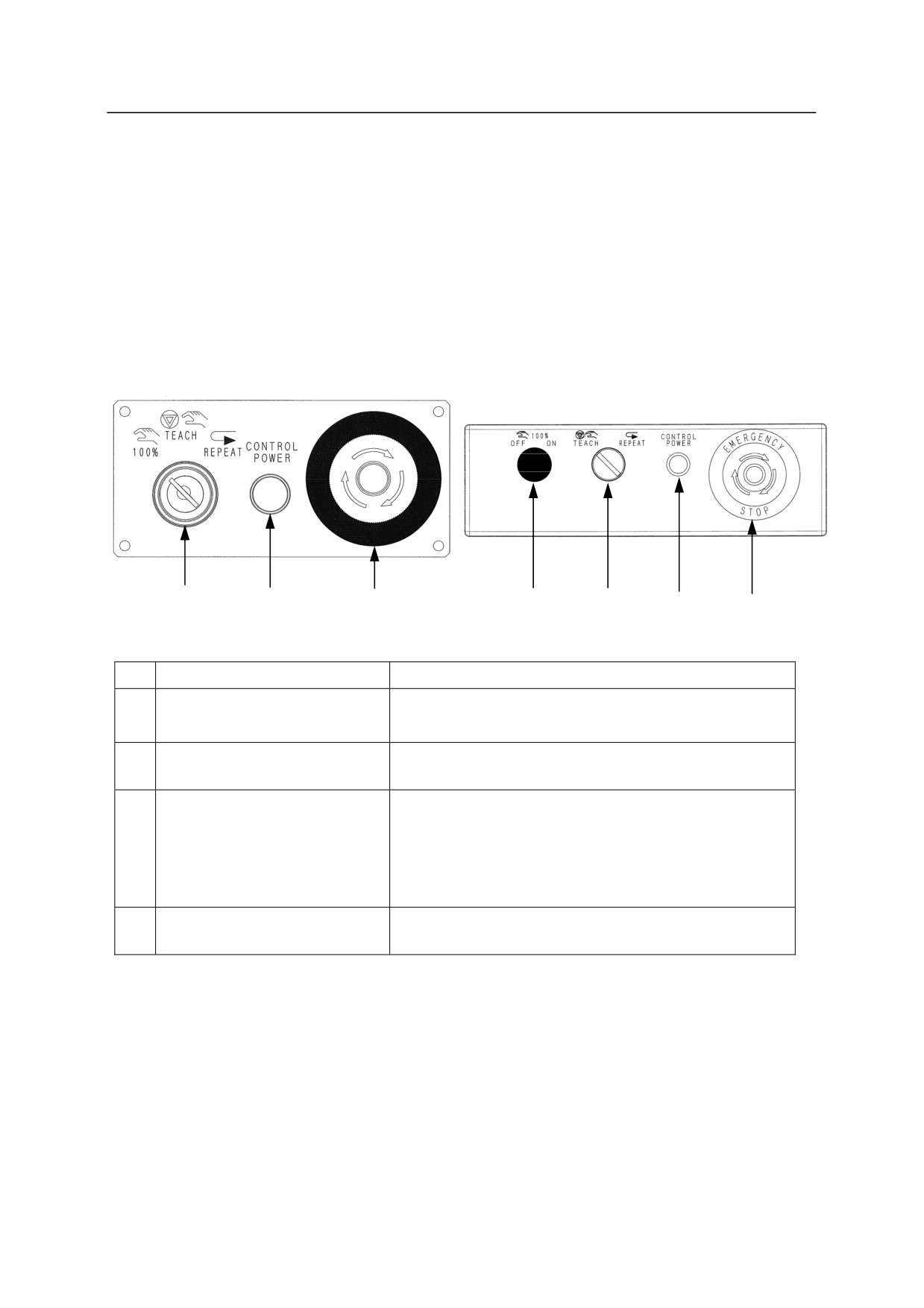
Following switches and lamps are equipped on the operation panel of the controller. Some
model may be equipped with optional operation panel.
Operation panel
Europe spec. (Standard)
E0x controller
1
2
3
4
1
2
3
(Option)
No.
Switch and Lamp
Function
1
100%/TEACH/REPEAT
Switches the mode to Fast check, Teach* or Repeat**.
(100%/Teach/Repeat switch)
2
CONTROL POWER
Lights when the controller power is ON.
(Controller power lamp)
3
Emergency stop button
Intercepts motor power and stops the robot when this
button is pressed in an emergency. At the same time,
the <MOTOR> lamp and <CYCLE> lamp on teach
pendant are turned OFF. However, the controller
power is not cut OFF.
4
100 % ON/OFF
Switches the mode to Fast check.
(Only E0x controller)
NOTE* Selected when teaching an instruction or its parameter to a robot or when operating a
robot manually using the operation console called TP. Repeat operation is not
possible while in teach mode though check operation is possible.
NOTE** The mode for automatic playback operation
NOTE*** Condition in which the robot automatically works and executes a memorized
program continuously.
7-1
7. Switches on the Robot Controller
7.2 OVERVIEW OF TEACH PENDANT
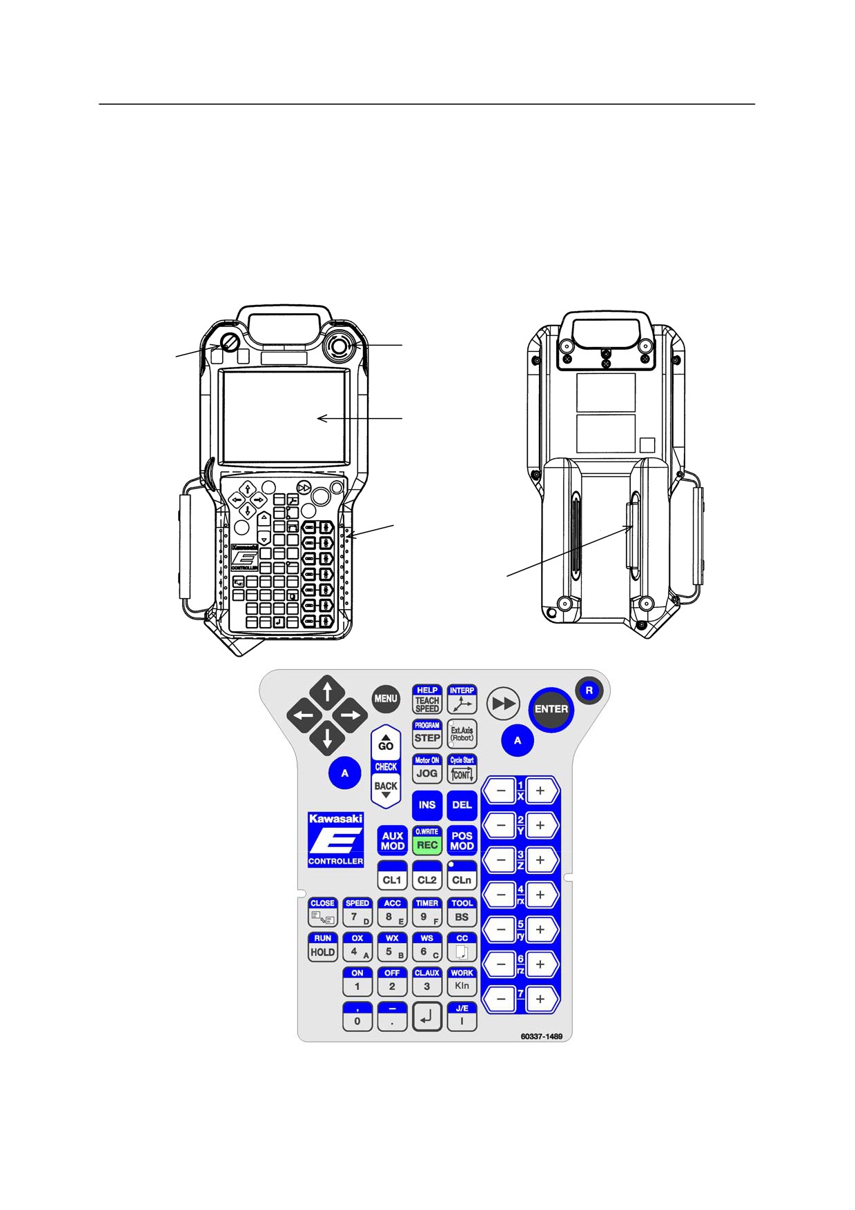
Figures below (top) show the overview of the teach pendant (hereinafter referred to as TP). TP
provides hardware keys and switches which are necessary for manual operation of robot and data
editing, and a screen for editing/displaying various kinds of data. Figure (bottom) shows the
arrangement of the hardware keys.
Emergency
stop switch
Teach lock
switch
Operation
screen
Hardware keys
Deadman switch
7-2
7. Switches on the Robot Controller
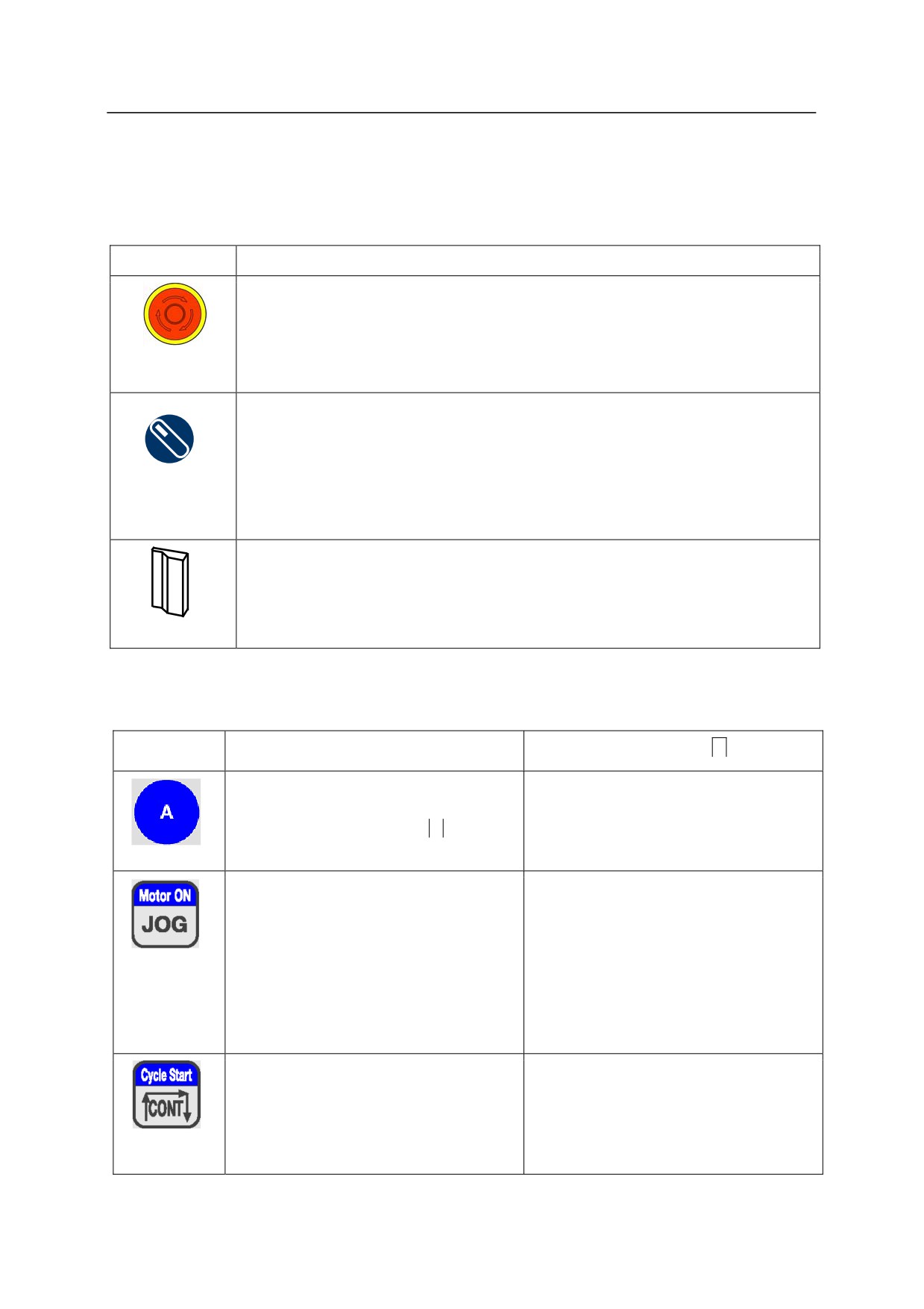
Following keys are the keys that are used the most on the teach pendant. Some of the keys other
than shown below may differ according to the option setting.
Switches
Switches
Function
Cuts OFF the motor power and stops the robot. To release emergency stop,
turn this button to the right until the button returns to its original position.
Emergency stop
Turning ON this switch (in teach mode) enables manual and check motions.
Turning OFF this switch (in automatic playback mode) enables repeat
operations.
Teach lock
Note: Make sure this switch is turned ON before starting teaching operation to
prevent robot from being operated in automatic playback mode
erroneously.
This is the enable switch. Robot axes cannot operate manually without
pressing this switch. Motor power cuts OFF and robot stops if switch is fully
depressed to its third deadman position, or if it is released completely.
Deadman
Hardware keys
Keys
Function
Functions when pressing
A key
Used with other key. The function on
the upper part of the key is enabled
when it is pressed with this
A key.
Increases robot motion speed in teach or
Turns ON the motor power when the
check mode.
motor power is OFF. Conversely,
Note: Effective only while being
turns OFF the motor power when the
pressed.
motor power is ON.
Note: Motor power cannot be turned
OFF during robot motion.
Sets how program is repeated in check
Starts cycle operation in automatic
mode. Toggles between Once and
playback mode.
Continuous.
Note: Turning controller power
switches to Check Once mode.
7-3
7. Switches on the Robot Controller
Keys
Function
Functions when pressing
A key
Moves each axis from JT1 to JT7.
Called
AXIS keys hereinafter.
Puts the robot into hold (stop) state.
Puts the robot into run (active) state.
7-4
8. Procedures for Power ON/OFF and Stopping the Robot
8.0 PROCEDURES FOR POWER ON/OFF AND STOPPING THE ROBOT
This chapter describes the power ON/OFF procedures for the robot controller and methods for
stopping the robot.
[ NOTE ]
This manual explains operation procedures assuming that the optional operation
panel is not used. When using the optional operation panel, both switches on
the TP and the optional operation panel can be used for turning ON/OFF motor
power and cycle operation start. However, for the robot activation (RUN),
robot will not activate unless both settings of the TP and optional operation panel
are RUN. That is, if the setting of the optional operation panel is HOLD, robot
cannot be activated even if
A+RUN on the TP is pressed.
8.1 POWER ON PROCEDURE
Ensure that all personnel are clear of the work cell, and that all safety devices are in place and
operational. Follow the steps below to turn ON the controller power first, and then the motor
power.
!
WARNING
When turning ON the controller power and motor power of the
robot controller, thorough attention should be taken to prevent
personnel from entering the motion range of the robot and the
peripheral equipment controlled by the robot controller. The
robot may move or operate accidentally when turning ON the
motor power, if the robot servo system is damaged.
8.1.1 CONTROLLER POWER ON PROCEDURE
1. Confirm that the external power is supplied to the controller.
2. Turn ON the
CONTROLLER POWER on the controller front.
8-1
8. Procedures for Power ON/OFF and Stopping the Robot
8.1.2 MOTOR POWER ON PROCEDURE
1. Ensure that all personal are clear of the work cell, and that all safety devices are in place and
operational.
(e.g.: door on safety fence is closed and safety plug is inserted, etc.)
2. Press
A +
MOTOR ON on the TP to turn ON. The motor power turns ON and the
<MOTOR> lamp on the top right of the TP screen illuminates at this time.*
NOTE* If motor power does not turn ON, read the contents displayed in the error screen and
system message area and restore the system accordingly, and then press
A +
MOTOR ON again.
!
DANGER
Before turning ON the controller power and the motor
power, ensure that all personnel are clear of the work cell and
that no interfering objects are around the robot(s).
8.2 POWER OFF PROCEDURE
Stop the robot and shut down the controller in the reverse order in which it was turned ON.
However, in the case of emergency, press the
EMERGENCY STOP immediately to cut OFF the
motor power.
1. Confirm the robot has completely stopped.
2. Press
HOLD or
A+<RUN> on the TP.
3. Press the
EMERGENCY STOP on the controller or the TP to cut OFF the motor power.*
NOTE* In automatic playback mode, turning the
TEACH/REPEAT on the controller to
TEACH also cuts OFF the motor power.
4. After the <MOTOR> lamp on the TP screen turns OFF, shut OFF the power by turning OFF
the
CONTROLLER POWER on the controller front.
8-2
8. Procedures for Power ON/OFF and Stopping the Robot
!
WARNING
When shutting down the controller power, press the
EMERGENCY STOP to cut OFF the motor power first, and
then turn OFF the
CONTROLLER POWER.
8.3 METHOD FOR STOPPING THE ROBOT
The methods for stopping the robot are different in teach mode and automatic playback mode.
1. In teach mode,
(1)
Release the
DEADMAN on the TP.
(2) Confirm that the robot has come to a complete stop, and press
HOLD or
A+<RUN> on
the TP.
2. In automatic playback mode,
(1) Confirm that the robot has come to a complete stop, and press
HOLD or
A+<RUN> on
the TP.
!
CAUTION
1. After robot has stopped, cut OFF power to the motors to disable
any further motion by pressing
EMERGENCY STOP.
2. Once motor power has been cut OFF, take measures to prevent
personnel from accidentally turning ON the power supply (tag
and lock out power switches, etc.).
8-3
8. Procedures for Power ON/OFF and Stopping the Robot
3. In emergency stop,
When the robot works abnormally and there is a possibility of danger such as injury, press
immediately any
EMERGENCY STOP wherever they are located, on the controller front,
TP, safety fence etc. to cut off the motor power.
Applying emergency stop may cause the error screen to pop up. To restart the robot from
this condition, reset errors before turning ON the motor power.
!
DANGER
Before moving the robot, ensure that all
EMERGENCY STOP on
the TP, controller and external emergency stop switches, etc. are
working correctly.
8-4
9. Teaching/ Automatic Playback
9.0 TEACHING/ AUTOMATIC PLAYBACK
9.1 TEACHING
Teaching is defined as creating a robot motion program by moving the robot manually using the
teach pendant. A program makes the robot work in accordance with other robots or peripheral
equipments to perform the required task.
9.2 AUTOMATIC PLAYBACK
In automatic playback, a taught program is played back automatically and the robot moves in
accordance with other robots and peripheral equipments to perform the required operation.
!
WARNING
For all teaching and automatic playback operations, risk assessment must be
performed for the whole robot system used in the operation. Take safety
measures and plan the operation procedures complying with international,
national, and local laws and standards. In addition to this, teaching and
automatic playback must only be done by certified personnel(s) who has
attended the Kawasaki prepared education/training course(s) pertinent to the
operation concerned.
9.3 EMERGENCY PROCEDURES
In case of emergency, any personnel available should be able to stop the robot by pressing the
EMERGENCY STOP button on the operation panel or the teach pendant.
Turn back ON the motor power to move the robot manually to an adequate position to restart
operation.
When the motor power does not turn back ON, a certified personnel who has completed the
special education and training course should perform the brake release procedure. Before
performing the brake release procedure, make sure that no parts fall off due to its own weight,
and if there is any axis or part that may fall, perform the necessary countermeasures as described
in the following section.
9-1
9. Teaching/ Automatic Playback
9-2
10. Brake Release Procedures for Emergency Cases
10.0 BRAKE RELEASE PROCEDURES FOR EMERGENCY CASES
The manual brake release switches allow the operator to move individual arm axes without using
motor power for maintenance and emergency situations.
(E0x/E70/E71/E91 controllers: Option,
E4x controllers: Standard)
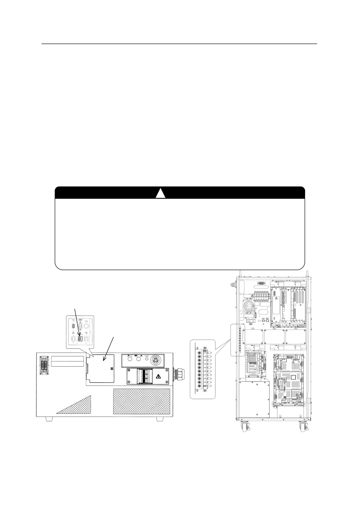
10.1 LOCATION OF BRAKE RELEASE SWITCH
The manual brake release switches are located:
E0x controller: Front of the controller (E0x controller, figure below left)
E4x controller: Inside the door on the controller (E4x controller, figure below right)
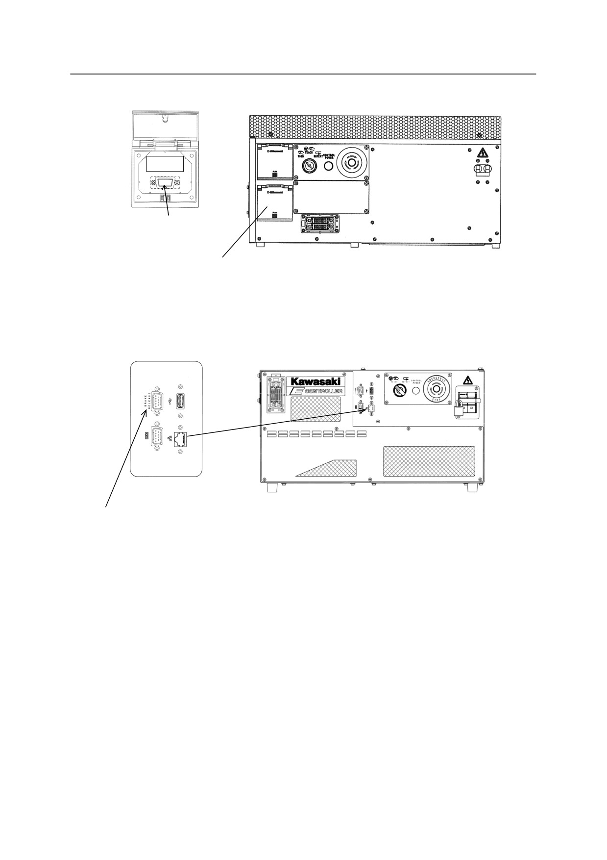
E70/E71/E91 controllers: Front of the controller (E70/E71/E91 controllers, figure on next page)
!
WARNING
When no servo power is applied, electromagnetic brakes lock to maintain the
robot arm posture. Unsupported axes may fall when the brake release switch
is pressed. Axes which are overhung, particularly JT2 and JT3, will fall the
fastest, depending on robot position, weight of the tool, and wrist axis position.
Position yourself to observe the entire robot arm and keep your eyes on the
arm when operating this switch.
Brake release connecting port
Accessory panel
Manual brake release switches
E0x controller
E4x controller
10-1
10. Brake Release Procedures for Emergency Cases
BRAKE
Brake release
connecting port
Brake release panel
Manual brake release switches
E70/E71 controllers
Accessory panel
Brake release
connecting port
E91 controller
10-2
10. Brake Release Procedures for Emergency Cases
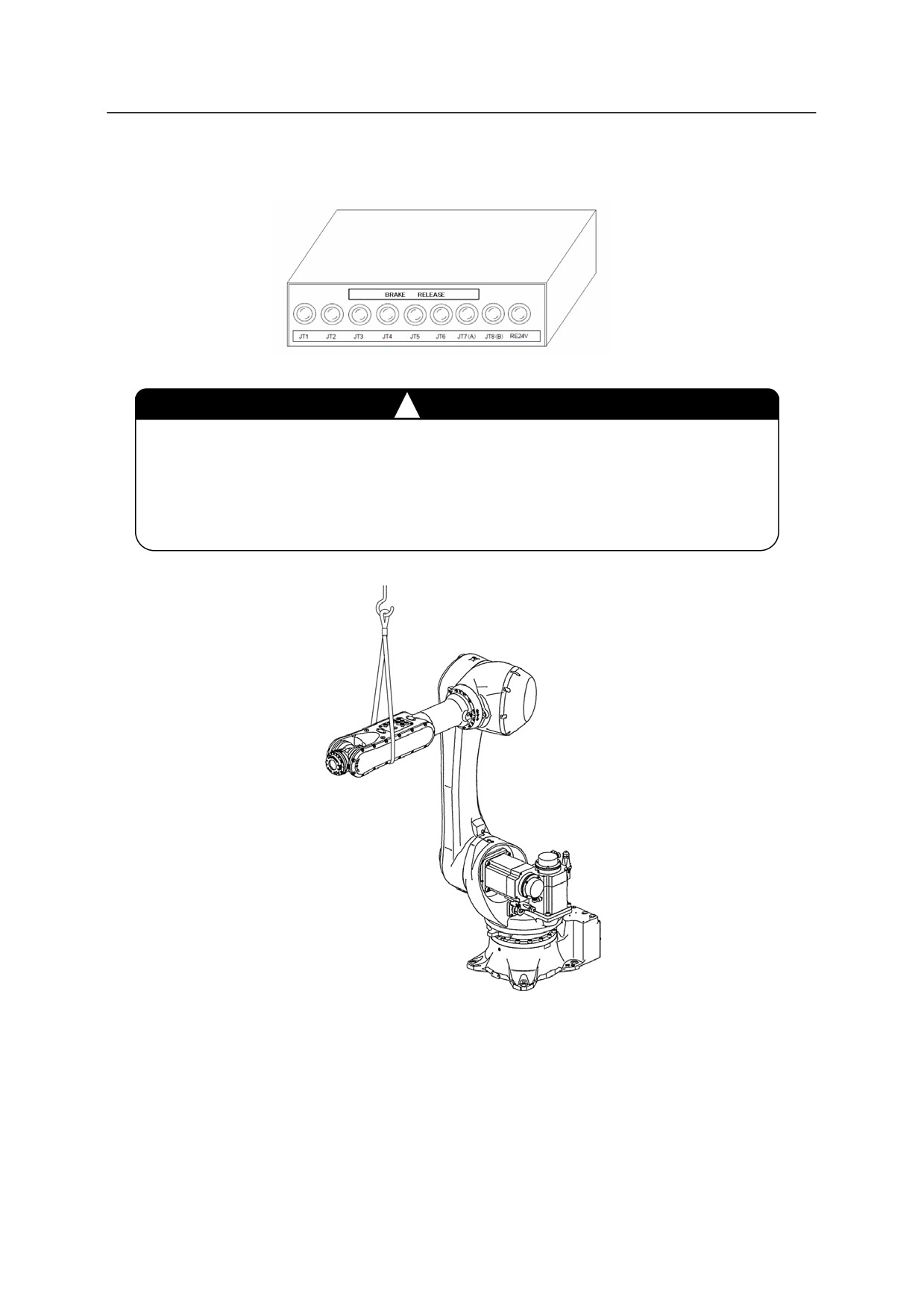
Connecting port of brake release switch is provided at the position shown in the figure.
䞉Brake release box is the option.
Brake release box
WARNING
!
To prevent injury to persons or damage to robotic equipment; provide suitable
support for the robot arm, tool and load, before using a brake release switch.
The robot arm can be supported from overhead using a sling and overhead
crane (Figure below).
Robot arm support
10-3
10. Brake Release Procedures for Emergency Cases
10.2 BRAKE RELEASE PROCEDURES
To manually release axes brakes use the following procedure.
1. Set motor power OFF.
2. Ensure all personnel are clear and all safety precautions are followed.
3. Provide suitable support of the robot arm, tool, and load if there is a risk of personal injury
(see above figure).
4. Open the access door to the manual brake release switches.
5. Ensure the switches are in the OFF position and in operating condition.
6. Press the brake release switch of the axis to release for a moment, and confirm that the brake
will not be released.
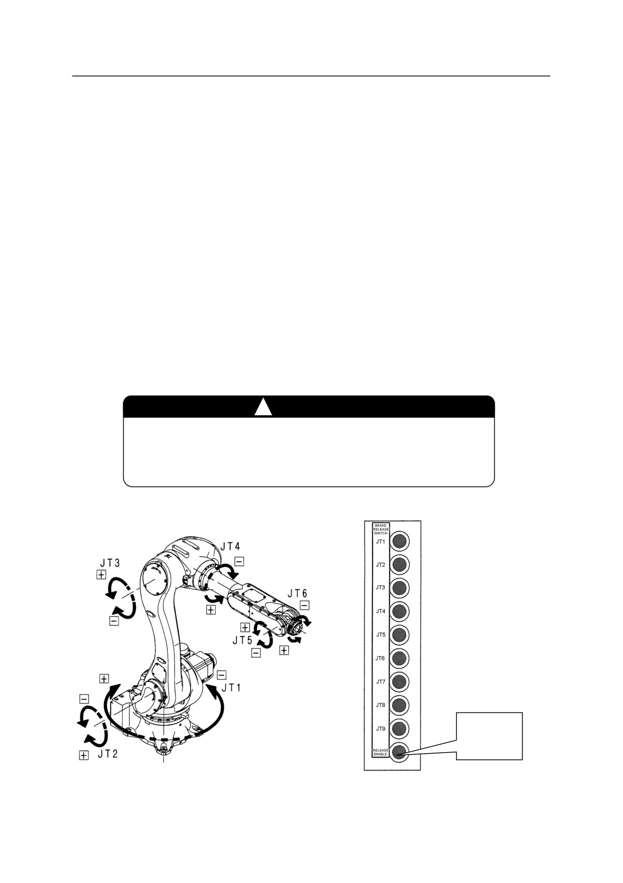
7. Press and hold the “RELEASE ENABLE” switch (see lower right figure). If the brake is
released at this time, do not use the switch (see CAUTION).
8. Press the manual brake release switch for the axis to release the brake (see lower right figure).
9. The brake remains released until the brake release switch is released.
10. After using the brake release switches, close the access door.
!
CAUTION
Stop using the manual brake release switch immediately if the
electromagnetic brake is released by pressing only one switch. The
switch may be defective.
RELEASE
ENABLE
Switch
Robot brake release axes
Manual brake release SW
10-4
11. Maintenance
11.0 MAINTENANCE
!
WARNING
For all maintenance operations, risk assessment must be performed for the
whole robot system used in the operation. Take safety measures and plan the
operation procedures complying with international, national, and local laws
and standards. In addition to this, maintenance operation must only be
done by certified personnel(s) who has attended the Kawasaki prepared
education/training course(s) pertinent to the operation concerned.
11.1 PRECAUTIONS FOR MOTOR REPLACEMENT PROCEDURES
!
WARNING
1. Prior to starting motor replacement, turn OFF control power up to the main
power source. Display signs indicating clearly “Inspection and Maintenance in
progress”, and lockout/ tagout the main power switch to prevent personnel from
accidentally turning ON the power.
2. When replacing a motor, support the arm safely using a crane/forklift truck or
place the arm on a support so as to prevent the arm from falling/rotating
accidentally by its own weight.
3. Servo motors are heavy, so be careful when handling it.
11-1