Loongson 1C300 Processor User Manual (Version 1.0, 2014) - page 4
Firstly, configure register Gamma Index to 0, indicating that the gamma adjustment starts from 0, and then the
Gamma Data register is configured 256 times to complete the configuration: 0, 2, 5, 6……
-58-

11 MAC Controller
11.1 DMA Register Description
Loongson 1C has integrated one MAC controller. The DMA controller integrated inside MAC cooperates with
MAC data transmission; this DMA controller can’t be used by other modules, and MAC can’t use other external
DMAs. MAC controller register include MAC register and DMA register. The start address of MAC register is
0xbfe1_0000, and that of DMA register is 0xbfe1_1000.
The significance of DMA register and MAC register is introduced in the below.
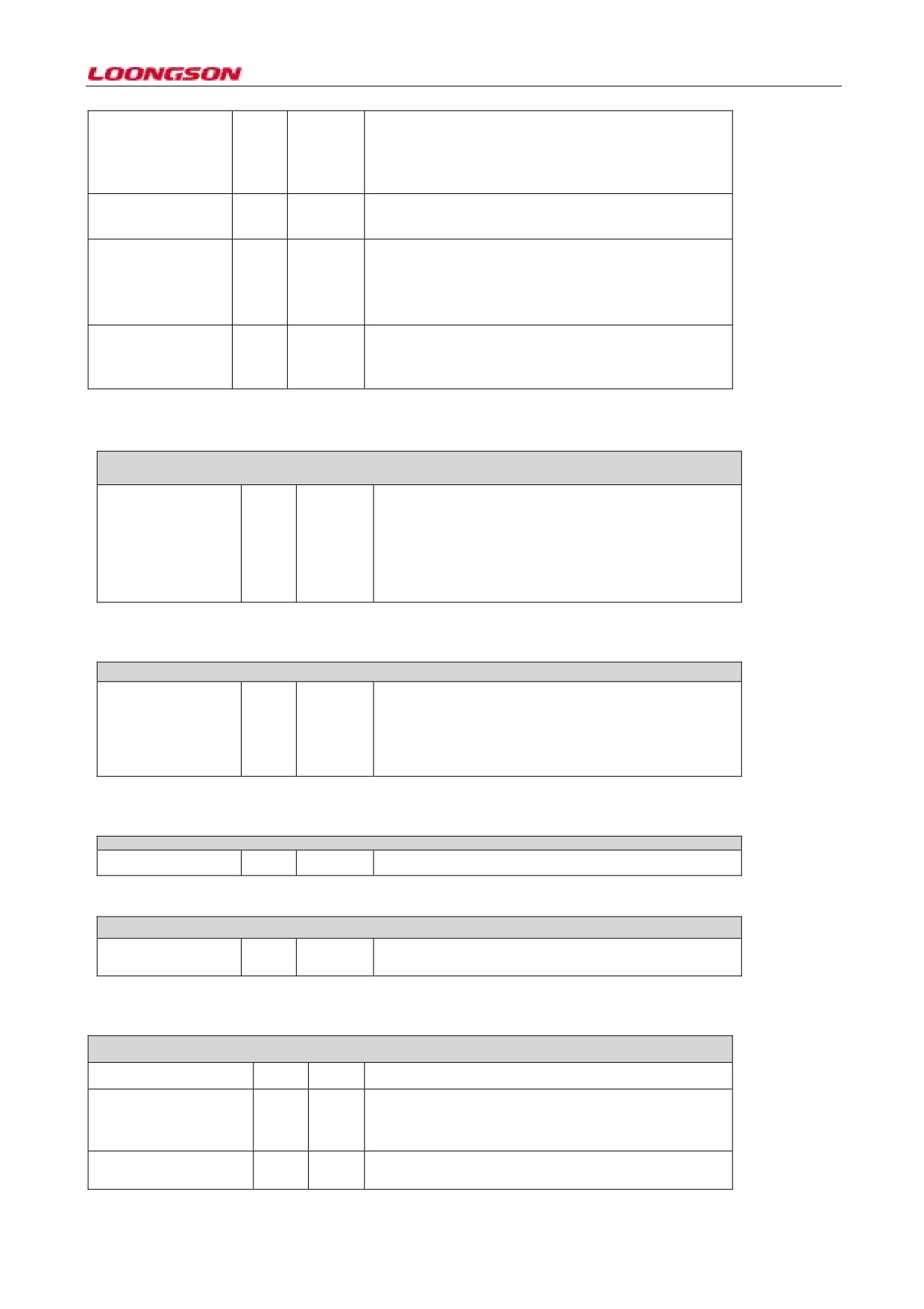
11.1.1 Register0 (Bus Mode Register)
Parameter
Bit
Default
Description
name
values
Register0 (Bus Mode Register) Offset: 0x00
31:27
0x0
Reserved, read only
Reserved
MB: Mixed Burst
26
0x0
When the bit is high, and FB bit is low, AXI master
adopts the INCR access mode when the burst access
length is longer than 16bit, and adopts the FIX access
mode when the burst access length is or shorter than
16. Users need not care about this bit setting.
AAL:
25
0x0
When this bit and FB bit are both high, all accesses of
AXI interface will be aligned to LS bit of the initial
Address-Aligned
address. If FB bit is 0, the initial access address isn’t
Beats
aligned, and the rest is aligned. Users need not care
about this bit setting.
24
0x0
When the bit is high, the maximum burst data
8XPBL Mode
transmission length of MAC DMA is 8,16,32,64,128
If enable PBLX8
or 256. The maximum burst length depends upon PBL.
mode
Users need not care about this bit setting.
23
0x0
When this bit is high, PBL value only applies to
USP:Use Separate
PBL
TxDMA. When this bit is low, PBL value only applies
to TxDMA and RxDMA. Users need not care about
this bit setting.
22:17
0x01
It indicates the maximum burst transmission length in
RPBL: RxDMA PBL
the first RxDMA transmission. Can only be 1, 2, 4, 8,
RxDMA burst
16 and 32, and other values are ineffective.
transmission length
16
0x0
It assigns whether AXI Master interface adopts FIX
FB Fixed Burst
burst transmission mode. Users need not care about
Fixed-length burst
this bit setting.
transfer length enable
15:14
0x0
Effective when DA bit is 0.
PR: Rx:Tx priority
ratio
00: 1: 1
01: 2: 1
10: 3: 1
11: 4: 1
13:8
0x21
Users need not care about this setting.
PBL: Programmable
Burst Length
-59-
7
0x0
When the bit is 1, the 32-byte descriptor is used.
ATDS: Alternate
Descriptor size
When the bit is 0, the 16-byte descriptor is used.
Whether to use 32
bytes size descriptor
6:2
0x00
Set 2 descriptor distances When the value is 0, it’s the
DSL: Descriptor Skip
size of DMA descriptor by default.
Length
1
0x0
0: adopt the alternative arbitration mechanism between
DA:DMA Arbitration
RxDMA and TxDMA
scheme
1: 1: RxDMA priority is higher than TxDMA priority
See specific ratio for PR value.
0
0x21
If this bit is set high, DMA controller will reset MAC
SWR:Software
internal register and logic. The bit is automatically
Reset
cleared when reset is finished.
11.1.2 Register2 (Receive Poll Demand Register)
Register1 (Transmit Poll Demand Register)Offset: 0x04
TPD: Transmit Poll31:0
0x0
Write any value to this value, sending DMA controller
Demand
will read the descriptor corresponding to register 18. If
the descriptor is invalid, DMA transmission will
terminate. If the descriptor is valid, DMA transmission
will continue.
11.1.3 Register2 (Receive Poll Demand Register)
Register2 (Receive Poll Demand Register) 0x08
RPBL: Receive Poll31:0
0x0
Write any value to this value, receiving DMA
Demand
controller will read the descriptor corresponding to
register
18. If the descriptor is invalid, DMA
transmission will terminate. If the descriptor is valid,
DMA transmission will continue.
11.1.4 Register3 (Receive Descriptor List Address Register)
Register3 (Receive Descriptor List Address Register)Offset: 0x0C
Start of Receive List
31:0
0x0
Starting address of directional reception descriptor
11.1.5 Register4 (Transmit Descriptor List Address Register)
Register4 (Transmit Descriptor List Address Register)Offset: 0x10
Start of Transmit List
31:0
0x0
Starting address of directional transmission descriptor
11.1.6 Register5 (Status Register)
Register5 (Status Register) Offset: 0x14
Reserved, read only
Reserved
31:30
29
0x0
Timestamp module triggering an interrupt. Read only.
TTI: Time-Stamp Trigger
Interrupt
28
0x0
Power supply management module triggering an
GPI: MAC PMT
interrupt. Read only.
-60-

Interrupt
27
0x0
MMC module triggering an interrupt. Read only.
GMI:MAC MMC
Interrupt
26
0x0
MAC module PCS or RGMII module trigger interrupt
GLI: MAC Line interface
Read only
Interrupt
25:23
0x0
23: 1'b1 TxDMA error during data transmission
EB: Error Bits
1'b0 RxDMA error during data transmission
24:1 'b1 reading transmission error
1'b0 writing transmission error
25:1 'b1 descriptor access error
1'b0 data cache access error
TS: Transmit
22:20
0x0
3'b000: transmit stop; reset or stop command
transmitting
Process State
3'b001: in progress; obtain transmit descriptor
3'b010: in progress; status of waiting for transmission
3'b011: in progress; read data from transmitting buffer,
and send to transmit FIFO (TxFIFO)
3'b100: write-in timestamp status
3'b10 1: reserved
3'b110: suspended; the traditional descriptor can’t be
used for the transmit buffer underflows
3'b111: operation; close transmit descriptor.
RS: Receive
19:17
0x0
3'b000: stop; reset or receive the stop command
Process State
3'b001: operation; obtain the receive descriptor
3'b010: reserved
3'b011: run; waiting to receive the package.
3'b100: pause; receive descriptor unavailable;
3'b101: operation; close the receive descriptor.
3'b110: timestamp writing status.
3'b111: operation; transfer the receive buffer from
package content to system memory
16
0x0
Prompt system if there is a normal interrupt.
NIS: Normal Interrupt
Summary
15
0x0
Prompt system if there is a normal interrupt.
AIS: Abnormal
Interrupt Summary
14
0x0
Prompt: DMA controller write the first data in package
ERI: Early Receive
to receive buffer
Interrupt Receive
13
0x0
Prompt bus error. See [25:23] for specific information.
FBI: Fatal Bus Error
When this bit is set
Interrupt
DMA engine stopping bus access operation.
12:11
0x0
Reserved
Reserved
-61-

10
0x0
Prompt that the Ethernet frame to be transmitted has been
ETI: Early Transmit
completely transmitted to the transmit FIFO in MTL
module
Interrupt
0x0
Prompt that one over 2048-byte Ethernet frame is received
RWT: Receive Watchdog9
(when the huge frame is enabled, it prompts that one over
Timeout
10240bytes Ethernet frame has been received)
8
0x0
Indicate reception process stop
RPS: Receive Process
Stopped
7
0x0
Indicate unavailable reception buffer
RU: Receive Buffer
Unavailable
6
0x0
Indicate frame reception completion The status
RI: Receive Interrupt
information received by frame has been written to the
descriptor. Reception in running status
5
0x0
Receive underflow exists in indicate frame transmission
UNF: Transmit
process
Underflow
4
0x0
Receive overflow exists in indicate frame receive process
OVF: Receive Overflow
3
0x0
TJT:Transmit
Jabber Timeout
2
0x0
It prompts that the next descriptor in transmission list can
TU: Transmit Buffer
be accessed by DMA controller.
Unavailable
1
0x0
Prompt transmission process stop
TPS: Transmit Process
Stopped
0
0x0
Prompt the completion of frame transmission and the 31st
TI: Transmit Interrupt
bit set of the first descriptor
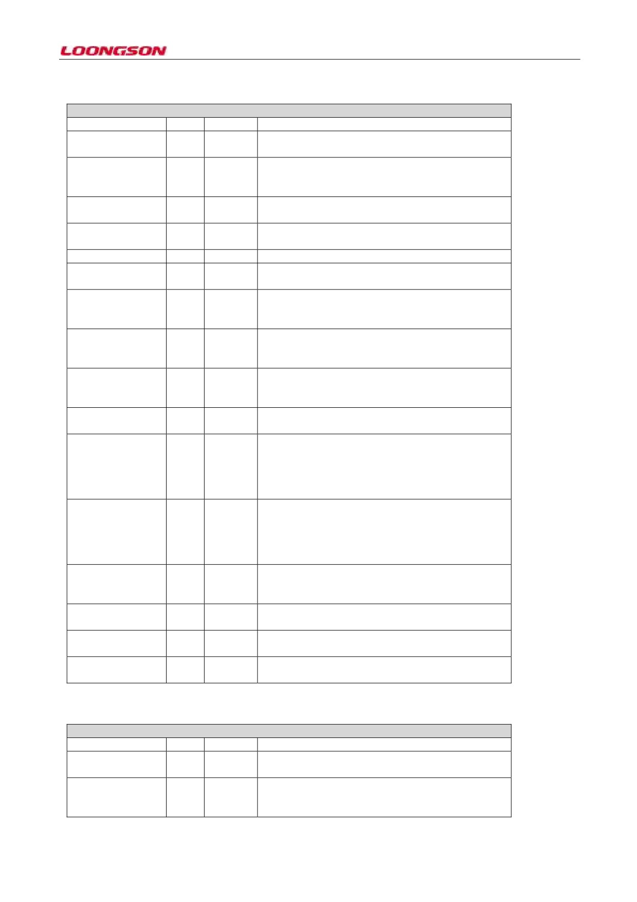
11.1.7 Register0 (Bus Mode Register)
Register6 (Operation Mode Register)Offset: 0x18
Reserved
31:27
0x0
Reserved
DT
26
0x0
When the bit is 1, MAC won’t abandon the Ethernet
Close and abandon
frame with checksum error
the Ethernet frame
with
TCP/IP
Checksum error
RSF: Receive Store
25
0x0
When the bit is 1, the MTL module only receively the
and Forward
Ethernet frame completely stored in the receive
FIFO.
DFF:
Disable24
0x0
When the bit is 1, don’t wash out any Ethernet frame
Flushing of Received
if the receive DMA is unavailable in receive
Frames
descriptor or buffer.
RFA[2]: MSB of23
0x0
100: maximum value minus 5KB
Threshold
for
101: maximum value minus 6KB
Activating
Flow
110: maximum value minus 7KB
Control
111: reserved
(Note: a maximum value of 8KB)
RFD[2]: MSB of 22
0x0
100: maximum value minus 5KB
Threshold
for
101: maximum value minus 6KB
-62-

Deactivating
Flow
110: maximum value minus 7KB
Control
111: reserved
(Note: a maximum value of 8KB)
TSF: Transmit Store 21
0x0
When the bit is 1, the content that the frame sends all
and Forward
enters in the transmit FIFO of MTL.
FTF:Flush Transmit
20
0x0
When the bit is 1, the transfer control logic is reset to
FIFO
the default, and will cause the sent data in FIFO to be
completely lost.
Reserved
19:17
0x0
Reserved
TTC:Transmit
16:14
0x0
When the frame size exceeds this value, MTL will
Threshold Control
transmit this frame.
000: 64 bytes
001: 128 bytes
010: 192 bytes
011: 256 bytes
100: 40 bytes
101: 32 bytes
110: 24 bytes
111: 16 bytes
ST:Start/Stop
13
0x0
When this bit is 1, the transmission enters into the
Transmission
running state. When this bit is 0, the transmission
Command
enters into the halted state.
RFD:Threshold for12:11
0x0
00: Maximum value minus 1KB
deactivating
flow
01: Maximum value minus 2KB
control
10: Maximum value minus 3KB
11: Maximum value minus 4KB
( Maximum value of 8KB)
RFA:Threshold for10:9
0x0
00: Maximum value minus 1KB
Activating
flow
01: Maximum value minus 2KB
control
10: Maximum value minus 3KB
11: Maximum value minus 4KB
(Maximum value of 8KB)
EFC: Enable HW 8
0x0
When the bit is 1, the hardware flow control circuit
flow control
based on receive FIFO will be effective.
FEF:Forward Error7
0x0
When the bit is 1, the error frame is received (error
Frames
frame includes CRC error collision error, Jumbo
frame, Watchdog timeout, overflow, and the like.)
FUF:Forward
6
0x0
When the bit is 1, the receive FIFO will receive the
Undersized
Good
Ethernet frame without error but smaller than
64
Frames
bytes.
Receive
error-free
small frames
Reserved
5
0x0
Reserved
RTC:
Receive4:3
0x0
The content that MTL transmits in receive FIFO has
Threshold Control
exceeded the set size.
00: 64 bytes
01:32 bytes
10: 96 bytes
11: 128 bytes
OSF:
Operation
2
0x0
When the bit is high, DMA can start to process the
Second Frame
second Ethernet frame when the status of the first
Ethernet frame has been written.
SR:Start/Stop
1
0x0
When the bit is set high, the receiving enters into the
Receive
running state. When the bit is set low, the receiving
enters into the halted state.
Reserved
0
0x0
Reserved
-63-
11.1.8 Register7 (Interrupt Enable Register)
Register7 (Interrupt Enable Register)Offset: 0x1C
Reserved
31:17
0x0
Reserved
NIE:Normal Interrupt 16
0x0
When the bit is 1: if the bit of the normal interrupt
Summary Enable
enable is 0: the normal interrupt disable
AIE:
Abnormal15
0x0
When this bit is 1: abnormal interrupt enable. When
Interrupt
Summary
this bit is 0: abnormal interrupt disable.
Enable
ERE: Early Receive
14
0x0
When this bit is high: early receive interrupt enable
Interrupt Enable
FBE:Fatal Bus Error 13
0x0
When the bit is high: bus fatal error interrupt enable
Enable
Reserved
12:11
0x0
Reserved
ETE: Early Transmit10
0x0
When this bit is high: early enable transmission
Interrupt Enable
interrupt
RWE:
Receive9
0x0
When this bit is high: enable receive watchdog timeout
Watchdog Timeout
interrupt.
Interrupt Enable
RIE:
Receive8
0x0
When this bit is high: enable receive stopped interrupt.
Stopped
Interrupt
Enable
RUE: Receive
7
0x0
When the bit is high, enable the receive buffer
Buffer Unavailable
unavailable interrupt.
Interrupt Enable
RIE:
Receive6
0x0
When this bit is high: enable receive interrupt.
Interrupt Enable
UNE:
Underflow5
0x0
When the bit is high: enable transmit FIFO underflow
Interrupt
Enable
interrupt
Transmit
FIFO
underflow interrupt
enable
OVE:
Overflow4
0x0
When the bit is high: enable receive FIFO overflow
Interrupt
Enable
interrupt
Receive
FIFO
overflow
interrupt
enable
TJE:
Transmit3
0x0
When the bit is high: enable Jabber timeout interrupt
JabberTimeout
Enable
TUE:Transmit Buffer 2
0x0
When the bit is high: enable transmit buffer
Unavailable Enable
unavailable interrupt
TSE:
Transmit1
0x0
When this bit is high: enable transmit stopped
Stopped Enable
interrupt.
TIE:
Transmit0
0x0
When this bit is high: enable transmission interrupt
Interrupt Enable
11.1.9 Register8 (Missed Frame and Buffer Overflow Counter Register)
Register8 (Missed Frame and Buffer Overflow Counter Register)Offset: 0x02
Reserved
31:29
0x0
Reserved
Overflow bitfor FIFO28
0x0
FIFO overflow indicating bit
Overflow Counter
Indicates the number27:17
0x0
Indicate missing frame numbers of the application
of frames missed by
programs
the application
-64-

Overflow bit for16
0x0
Indicates the number of missed frame has exceeded the
Missed
Frame
maximum value
Counter
Indicates the number15:0
0x0
Indicates the number of frames missed by the controller
of frames missed by
due to the Host Receive Buffer being unavailable
the controller due to
the Host Receive
Buffer
being
unavailable
11.1.10 Register9(Receive Interrupt Watchdog Timer Register)
Register9(Receive Interrupt Watchdog Timer Register)Offset: 0x24
Reserved
31:8
0x0
RIWT: RI Watchdog7:0
0x0
When the Watchdog is set, it indicates the count in the
Timer count
unit of the clock cycle x 256 When DMA receives the
data packet, and the count starts when the RI bit in
status register is 0, when the Watchdog timer times out,
RI bit is set to 1. The domain resets when RI bit is 1
11.1.1 Register0 (Bus Mode Register)
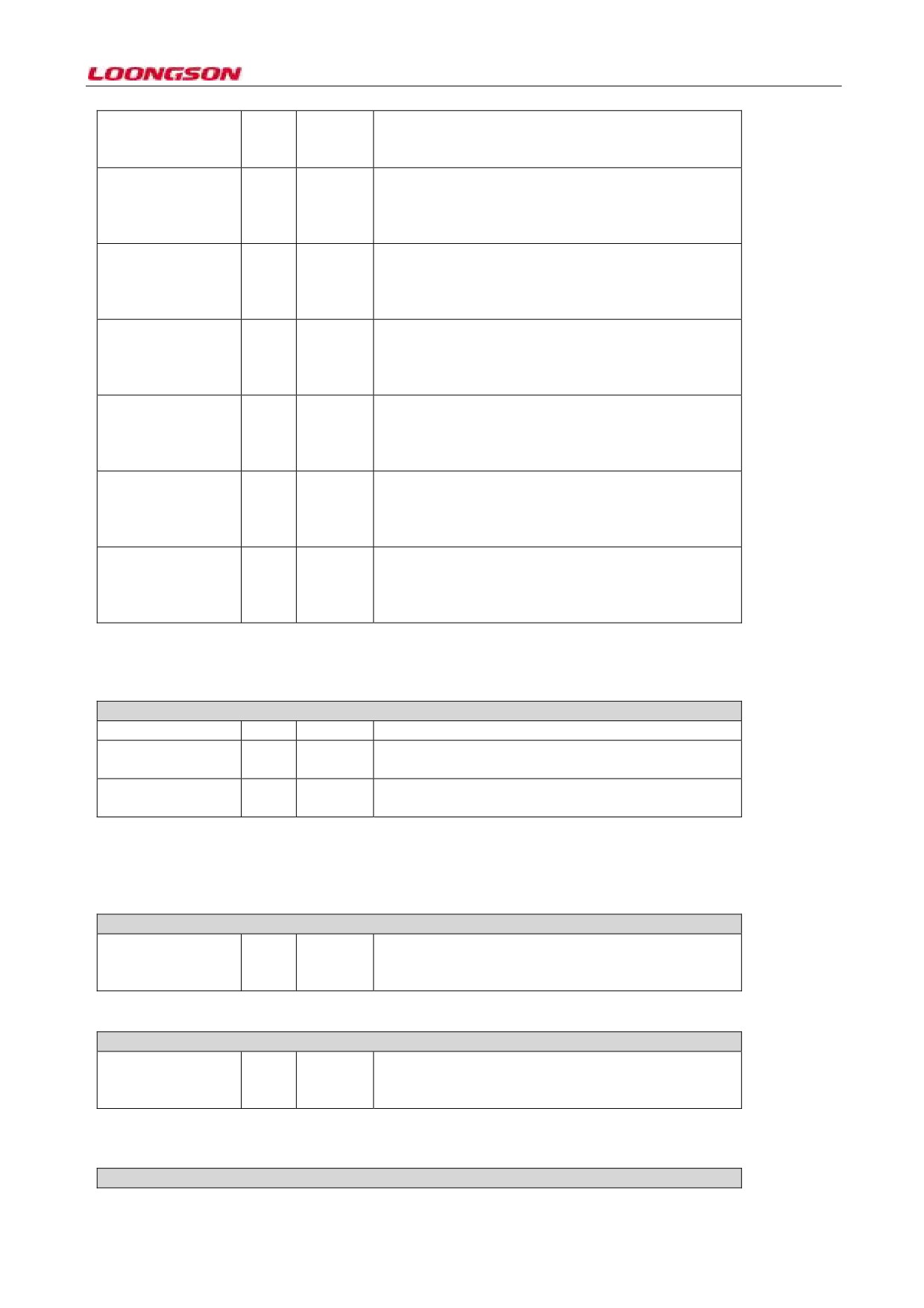
Register10 (AXI Bus Mode Register)Offset: 0x28
31
0x0
When the bit is 1, the low power interface is enabled,
EN_LPI: Enable LPI
and the system receives the LPI request from AXI
(LowPower
system clock controller. When the bit is 0, the low
Interface)
power interface is disabled, and the system will refuse
the LPI request forever.
UNLCK_ON_MGK_30
0x0
When the bit is 1, if MAC is in low power state, it can
RWK:Unlock
on
return to the working state only by magic packet or
Magic Packet
or
remote wakeup; when the bit is 0, MAC is under low
Remote Wake Up
power state, it can return to the working state via any
packet.
Reserved
29:23
0x0
WR_OSR_LMT:
22:20
0x0
This bit has set up the maximum outstanding request
AXI Maximum Write
number sent by AXI interface write operation.
Outstanding Request
Limit
AXI
maximum
outstanding
Write out request
Reserved
19
0x0
WR_OSR_LMT:
18:16
0x0
This bit has set up the maximum outstanding request
AXI Maximum Read
number sent by AXI interface read operation.
Outstanding Request
Limit
Reserved
15:13
0x0
AXI_AAL:
12
0x0
This bit is only-read, and is the same with AAL bit 0.
Address-Aligned
Beats
Reserved
11:8
0x0
BLEN256: AXI Burst7
0x0
Only when AXI_BURST_LENGTH is configured to
Length 256
256, can this bit be significant; when the bit is 1, it
indicates that AXI supports the request of Burst length
of 256; or, it’’ be reserved.
BLEN256: AXI Burst6
0x0
Only when AXI_BURST_LENGTH is configured to
-65-
Length 128
128, can this bit be significant; when the bit is 1, it
indicates that AXI supports the request of Burst length
of 128; or it is be reserved.
BLEN256: AXI Burst5
0x0
Only when AXI_BURST_LENGTH is configured to
Length 64
64, can this bit be significant; when the bit is 1, it
indicates that AXI supports the request of Burst length
of 64; or it will be reserved.
BLEN256: AXI Burst4
0x0
Only when AXI_BURST_LENGTH is configured to
Length 32
32, can this bit be significant; when the bit is 1, it
indicates that AXI supports the request of Burst length
of 32; or it will be reserved.
BLEN256: AXI Burst3
0x0
Only when AXI_BURST_LENGTH is configured to
Length 16
16, can this bit be significant; when the bit is 1, it
indicates that AXI supports the request of Burst length
of 16; or, it’’ be reserved.
BLEN256: AXI Burst 2
0x0
Only when AXI_BURST_LENGTH is configured to 8,
Length 8
can this bit be significant; when the bit is 1, it indicates
that AXI supports the request of Burst length of 8; or it
will be reserved.
BLEN256: AXI Burst
1
0x0
Only when AXI_BURST_LENGTH is configured to 4,
Length 4
can this bit be significant; when the bit is 1, it indicates
that AXI supports the request of Burst length of 4; or,
it’’ be reserved.
UNDEF:
AXI0
0x0
When the bit is 1, it indicates that AXI interface can
Undefined
Burst
send the request of any Burst length. When the bit is 0,
Length
it indicates that AXI supports the request length that
bit7-1 defines to be 256/128/64/32/16/8/4 or 1.
11.1.12 Register11 (AXI Status Register)
Register11 (AXI Status Register)Offset: 0x2C
Reserved
31:2
0x0
1
0x0
When the bit is 1, it indicates that the current AXI is
sending read request.
0
0x0
When the bit is 1, it indicates that the current AXI is
sending read request.
Register12- Register18: Reserved
11.1.13 Register18 (Current Host Transmit Descriptor Register)
Register18 (Current Host Transmit Descriptor Register)Offset: 0x48
Host
Transmit31:0
0x0
Read only
Descriptor Address
Pointer
11.1.14 Register19 (Current Host Receive Descriptor Register)
Register19 (Current Host Receive Descriptor Register)Offset: 0x4C
Host
Receive31:0
0x0
Read only
Descriptor
Address
Pointer
11.1.15 Register20 (Current Host Transmit Buffer Address Register)
Register20 (Current Host Transmit Buffer Address Register)Offset: 0x05
-66-
Host Transmit Buffer 31:0
0x0
Read only
Address Pointer
11.1.16 Register21 (Current Host Receive Buffer Address Register)
Register21 (Current Host Receive Buffer Address Register)Offset: 0x54
Host Receive Buffer 31:0
0x0
Read only
Address Pointer
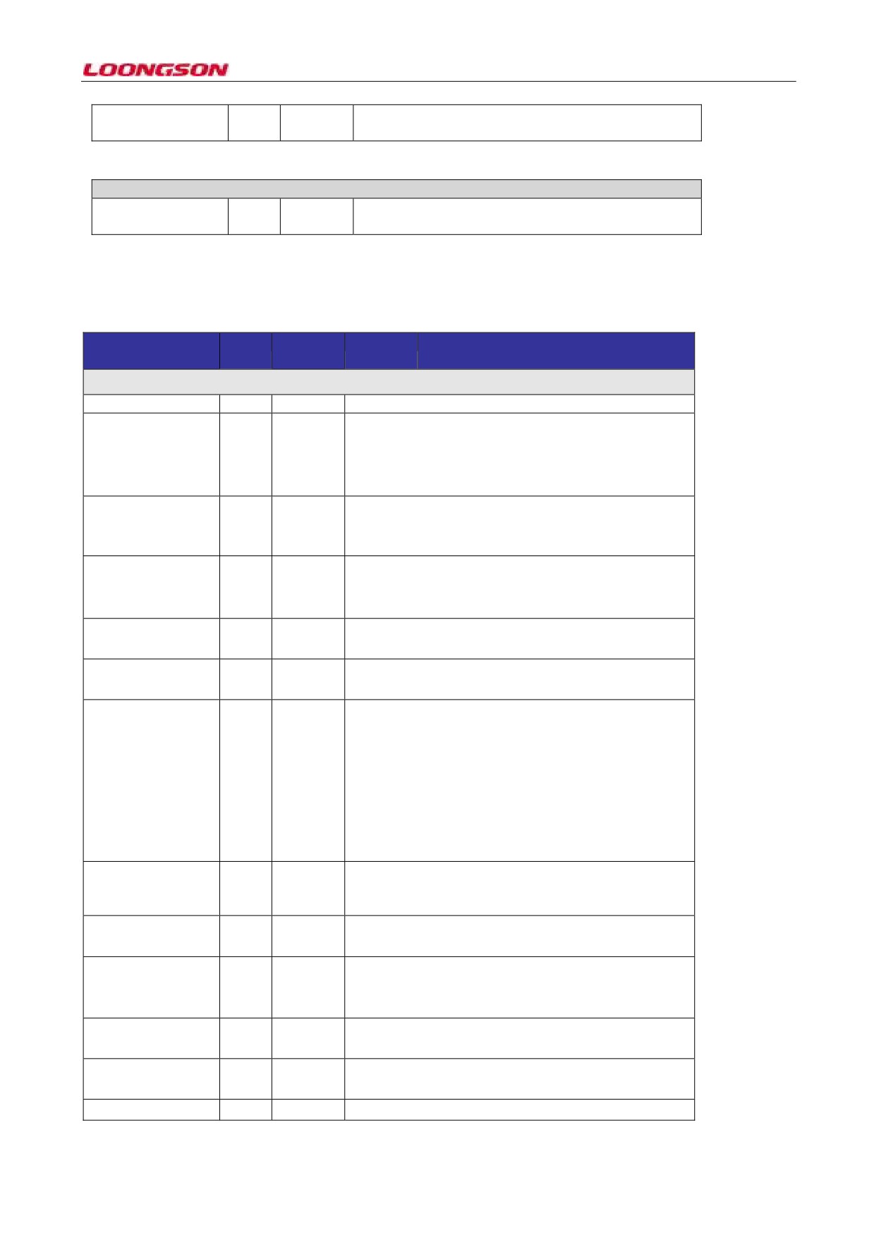
11.2 MAC Controller Register Description
11.2.1 Register0 (MAC Configuration Register)
Parameter
Bit
Default
Scope
Description
name
values
Register0 (MAC Configuration Register) Offset: 0x0000
Reserved
31:26
0x0
Reserved
TCH:
Transmit
24
0x0
When the bit is high, it’ll transmit messages such as
Configuration
in
duplex mode, link speed, link and link
RGMII
connection/disconnection to PHY through RGMII
interface.
WD:
Watchdog
23
0x0
When the bit is high, MAC will disable the watchdog
Disable
timer in RxD, and can receive the Ethernet frame as
large as 16384 bytes.
JD: Jabber Disable
0x0
When the bit is high, MAC will close the Jabber timer
22
during transmission, and can send the Ethernet frame as
large as 16384 bytes.
BE: Frame Burst
21
0x0
When the bit is high, MAC enables the frame burst
Enable
transmission mode.
JE: Jumbo Frame
20
0x0
When the bit is high, MAC enables the Jumbo frame
Enable
receive (as large as 9018 bytes).
IFG:
Minimum
19:17
0x0
Set the minimum inter-frame gap during transmission
Inter-Frame Gap
process
000: 96 bit-time
001: 88 bit-time
010: 80 bit-time
….
111: 40 bit-time
DCRS:
Disable
16
0x0
When the bit is high, MAC will ignore the detection of
Carrier Sense During
CRS signal in half-duplex mode.
Transmission
PS: Port Select
15
0x0
0: GMII (1000Mbps)
1: MII(10/100Mbps)
FES: Speed
14
0x0
0: 10Mbps
Fast Ethernet speed
prompt
1: 100Mbps
DO: Disable Receive
13
0x0
When the bit is high, MAC doesn’t receive the valid
Own
Ethernet frame of gmii_txen_o in half-duplex mode.
LM: Loopback Mode
12
0x0
When the bit is high, GMII/MII works in loopback
mode.
DM: Duplex Mode
11
0x0
When the bit is high, MAC works in full-duplex mode,
-67-

and it can send and receive the Ethernet frame
simultaneously in full-duplex mode.
IPC:
Checksum
10
0x0
When the bit is high, MAC hardware computes the
Offload Enable
received payload of Ethernet frame. It also checks the
checksum of IPV4 head
DR: Disable Retry
9
0x0
When the bit is high, when encountering the collision,
MAC won’t retransmit the Ethernet frame, and only
report the collision error.
LUD: Link Up/Down
8
0x0
0: Link disconnect
1: Link connection
ACS:
Automatic
7
0x0
When the bit is 1, MAC eliminates the Pad and FCS in
Ethernet
frame
the received Ethernet frame.
Pad/CRC Stripping
BL: Back-Off Limit
6:5
0x0
The back-off limit decides the slot-based delay time
00: k=min(n,10)
01: k=min(n,8)
10: k=min(n,4)
11: k=min(n,1)
DC Deferral Check
4
0x0
When the bit is 1, enable deferral detection function
TE:
Transmitter
3
0x0
When the bit is 1, enable MAC transfer function
Enable
RE: Receiver Enable
2
0x0
When the bit is 1, enable MAC receive function
Reserved
1:0
0x0
Reserved
11.2.2 Register1 (MAC Frame Filter)
Register1 (MAC Frame Filter)Offset: 0x0004
RA: Receive All
31
0x0
When the bit is 1, MAC receive module transmits all
received frames to application, and ignore source
address/target address filtering mechanism.
Reserved
30:11
0x0
Reserved
HPF: Hash or Perfect
0x0
When the bit is 1, the Ethernet frame in Hashor Perfect
Filter
10
Filter system is sent to application.
When the bit is 0, only the Ethernet frame in Hashor
Perfect Filter system is sent to application.
SAF: Source Address9
0x0
MAC CORE compares the source address domain in
Filter Enable
the received Ethernet frame and the value in SA
register, and if they are matching, the SAMatch bit in
receive status register is set to high. When the bit is 1,
the source address matching fails, and MAC CORE
will lose the Ethernet frame.
When the bit is 0, no matter whether the source address
matching result receives MAC CORE, the matching
result will be written to receive status register.
SAIF: SA Inverse8
0x0
When the bit is 2, the Ethernet frame matching the
Filtering
source address in SA register will mark that the source
address matching fails.
When the bit is 0, the Ethernet frame mismatching the
source address in SA register will mark that the source
address matching fails.
PCF: Pass Control
7:6
0x0
00: MAC filters all control frames
Frames
01: MAC receives all control frames except pause
frame
-68-
10: M AC receives all control frames.
11: MAC receives the control frame based on address
filtering.
DBF:
Disable5
0x0
When the bit is 1, all received broadcast frames are
Broadcast Frames
filtered.
Receive all broadcast frames when this bit is 0
PM: Pass
All4
0x0
Receive all multicast frames when this bit is 1
Multicast
Filter all multicast frames when this bit is 0
DAIF: DA Inverse3
0x0
When the bit is 1, inverse target address matching is
Filtering
Target
conducted for unicast and multicast
address
inverse
When the bit is 0, inverse target address matching is
filtering
conducted for unicast and multicast
HMC:
Hash
2
0x0
When the bit is 1, the received multicast will conduct
Multicast
the target address filtering based on the contents in
Hash table.
HUC: Hash Unicast
1
0x0
When the bit is 1, the received unicast will conduct the
target address filter based on the contents in Hash table.
PR:Promiscuous
0
0x0
Receive all Ethernet frames.
Mode
11.2.3 Register2 (Hash Table High Register)
Register2 (Hash Table High Register)Offset: 0x0008
HTH: Hash Table31:0
0x0
Hash Table High 32-bit
High
11.2.4 Register3 (Hash Table Low Register)
Register3 (Hash Table Low Register)Offset: 0x0C
HTL:HashTable Low
31:0
0x0
Hash Table Low 32-bit
11.2.5 Register4 (GMII Address Register)
Register4 (GMII Address Register)Offset: 0x0010
Reserved
31:16
0x0
Reserved
PA: Physical Layer15:11
0x0
This domain chooses to assess which on in 32 PHYs.
Address
GR GMII Register
10:6
0x0
This domain chooses to access which GMII
The register in PHY
configuration register in PHY
device to access
Reserved
5
0x0
Reserved
CR:CSRClock Range
4:2
0x0
This domain decides whether MDC clock is clk_csr_i
clock frequency ratio.
0000 clk_csr_i/42
0001 clk_csr_i/62
0010 clk_csr_i/16
0011 clk_csr_i/26
0100 clk_csr_i/102
0101 clk_csr_i/124
0110, 0111 Reserved
GW: GMII Write
1
0x0
When the bit is 1, write operation is conducted to PHY
via GMII data register.
When the bit is 0, read operation is conducted to PHY
via GMII data register.
-69-

GB GMII Busy
0
0x0
Before the write operation in registers 4 and 5, this bit
should be written to 0. Before the register 4 is written,
this bit must be set to 0 first. When accessing to PHY
register, the application needs to set the bit to 1, and it
indicates that the write or read operation is under
progress in GMII interface.
11.2.6 Register5 (GMII Data Register)
Register5 (GMII Data Register)Offset: 0x0014
Reserved
31:16
0x0
Reserved
GD: GMII Data
15:0
0x0
This domain has saved 16 data in managing the read
access or the write access of PHY.
11.2.7 Register6 (Flow Control Register)
Register6 (Flow Control Register)Offset: 0x0018
PT: Pause Time
31:16
0x0
This field has saved the pause time domain in filling
out transmission control frame.
Reserved
15:8
0x0
Reserved
DZPQ:
Disable7
0x0
When the bit is 1, the generation of Zero-Quanta Pause
Zero-Quanta Pause
is disabled
Reserved
6
0x0
Reserved
PLT: Pause Low
5:4
0x0
This domain is used to set the pause time threshold.
Threshold
00: Pause time reduces 4 time slots
01: Pause time reduces 28 time slots
10: Pause time reduces 144 time slots
11: Pause time reduces 256 time slots
(one time slot is the transmission time of 512bytes or
64bit in GMII/MII interface)
UP Unicast Pause
3
0x0
When the bit is 1, MAC will detect the pause based on
Frame Detect
the station unicast address
RFE: Receive Flow
2
0x0
When the bit is 1, MAC will analyze the received stop
Control Enable
frame, and pause the frame transmit based on the time
specified by pause frame
TEF: Transmit Flow1
0x0
In full-duplex mode, when the bit is 1, MAC enables
Control Enable
the transmission of pause frame.
In half-duplex mode, when the bit is 1, MAC enables
the backpressure operation.
FCB
/ BPA: Flow0
0x0
When the bit is 1, in full-duplex mode, the pause frame
Control
is transmitted or in half-duplex mode, the backpressure
Busy/Backpressure
operation is initiated.
Activate
11.2.8 Register7 (VLAN Tag Register)
Register7 (VLAN Tag Register)Offset: 0x1C
Reserved
31:17
0x0
Reserved
ETV: Enable
12-Bit16
0x0
When the bit is
1, Enable
12-Bit VLAN Tag
VLAN
Tag
Comparison instead of 16-bit VLANTag to compare
Comparison
and filter Ethernet frames.
VL:VLAN
Tag15:0
0x0
This domain saves the VLAN Tag in the format of
Identifier for Receive
802.1Q, and uses it to compare the
15 and 16-bit
Frames
VLAN Tag in the received Ethernet frame.
-70-
11.2.9 Register8 (Version Register)
Register8 (Version Register)Offset: 0x02
Reserved
15:8
0x0
Reserved
Version
7:0
0x0
0X35
11.2.10 Register14 (Interrupt Status Register)
Register14 (Interrupt Status Register)Offset: 0x0038
Reserved
15:8
0x0
Reserved
MMCReceive Check7
0x0
When the MMC Receive Checksum Offload register
sum Offload Interrupt
generates any interrupt, this bit is set to 1.
Status MMC
MMC Transmit
6
0x0
When MMC transmit interrupt register generates any
Interrupt Status
interrupt, this bit is set to 1.
MMCReceive
5
0x0
When MMC receive interrupt register generates any
Interrupt Status
interrupt, this bit is set to 1.
MMC InterruptStatus
4
0x0
When any bit of 7:5 is high, this bit is set to 1.
PMT Interrupt Status
3
0x0
In Power Down state, when the magic frame or
Wake-on-LAN is received, this bit is set to 1.
PCS
2
0x0
When the RGMII PHY interface finishes the
Auto-Negotiation
negotiation automatically, this bit is set to 1.
PCS Link Status1
0x0
In the event of any change in the link status of RGMII
Changed
PHY interface, this bit is set to 1.
RGMIIInterrupt
0
0x0
In the event of any change in the link status of RGMII
Status
interface, this bit is set to 1.
11.2.11 Register15 (Interrupt Mask Register)
Register15 (Interrupt Mask Register)Offset: 0x0C
Reserved
15:10
0x0
Reserved
TimeStamp Interrupt9
0x0
When the bit is 1, the Time stamp interrupt is disabled.
Mask
Timestamp interrupt
enable
Reserved
8:4
0x0
Reserved
PMT Interrupt Mask
3
0x0
When the bit is
1, the interrupt caused on power
management is disabled.
PCSAN Completion
2
0x0
When the bit is
1, PCS auto negotiation complete
Interrupt Mask
interrupt is disabled.
PCSLinkStatus
1
0x0
When the bit is 1, the interrupt caused by the change in
Interrupt Mask
PCS link status is disabled.
RGMIIInterrupt
0
0x0
When the bit is 1, the interrupt caused by RGMII is
Mask
disabled.
11.2.12 Register16 (MAC Address0 High Register)
Register16 (MAC Address0 High Register)Offset: 0x0040
MO: Always 1
31
0x0
Reserved
Reserved
Reserved
30:16
0x0
Reserved
MAC
15:0
0x0
Store the MAC address used to receive address filtering
-71-
Address0[47:32]
and transmit flow control frame.
MAC address high
16-bit
11.2.13 Register17 (MAC Address0 Low Register)
Register17 (MAC Address0 Low Register)Offset: 0x0044
MAC Address0[31:0]31:0
0x0
Store the MAC address used to receive address filtering
MAC address low
and transmit flow control frame.
32-bit
11.2.14 Register18 (MAC Address1 High Register)
Register18 (MAC Address1 High Register)Offset: 0x0048
AE:Address Enable
31
0x0
When the bit is 1, the address filtering module uses the
2nd MAC address for complete address filtering. When
the bit is 0, the address filter module doesn’t use the 2nd
MAC address for address filter.
SA:Source Address
30
0x0
When the bit is 1, MAC address 1 is used to compare
Source MAC address
the source MAC address of receive frame.
When the bit is 0, MAC address 1 is used to compare
the target MAC address of receiving frame.
MBC: Mask Byte29:24
0x0
This domain is used to compare the byte mask control
Control
bit in each MAC address. For example, the 29th bit is
used to mask [15:8] in mask register 18.
Reserved
23:16
0x0
Reserved
MAC
15:0
0xFFFF
Address1[47:32]
The second MAC
address high 16-bit
11.2.15 Register19 (MAC Address1 Low Register)
Register19 (MAC Address1 Low Register)Offset: 0x0C
MAC Address1[31:0]31:0
0x0
The second MAC
address low 32-bit
11.2.16 Register48 (AN Control Register)
Register48 (AN Control Register)Offset: 0x0C
Reserved
31:19
0x0
Reserved
SGMII RAL Control
18
0x0
Reserved
Reserved
LR:
Lock
to17
0x0
When the bit is 1, PHY will lock its phase-locked loop
Reference
to the 125MHz reference clock.
ECD: Enable Comma
16
0x0
When the bit is
1, the pause detect and word
Detect
resynchronization of PHY are enabled
Reserved
15
0x0
Reserved
ELE:
External14
0x0
When the bit is 1, enable PHY enters into loopback
Loopback Enable
mode.
Reserved
13
0x0
Reserved
ANE:
12
0x0
When the bit is 1, MAC will automatically negotiate
Auto-Negotiation
with the link.
Enable
Reserved
11:10
0x0
Reserved
RAN:
Restart9
0x0
When the bit is 1, the auto-negotiation restarts.
Auto-Negotiation
Reserved
8:0
0x0
Reserved
-72-
11.2.17 Register49 (AN Status Register)
Register49 (AN Status Register)Offset: 0x1c280018
Reserved
31:9
0x0
Reserved
ES: Extended Status
8
0x0
It’s only-read, because MAC supports the expansion
state message.
Reserved
7:6
0x0
Reserved
ANC:
5
0x0
It’s read-only, indicates that auto-negotiation is
Auto-Negotiation
completed.
Complete
Reserved
4
0x0
Reserved
ANA:
3
0x0
It’s
only-read, because MAC supports the
Auto-Negotiation
auto-negotiation.
Ability
LS: Link Status
2
0x0
When this bit is set to
1, indicating the link is
connected. When this bit is 0, indicating the link is
disconnected.
Reserved
1:0
0x0
Reserved
11.2.18 Register50 (Auto-Negotiation Advertisement Register)
Register50 (Auto-Negotiation Advertisement Register)Offset: 0x0C
Reserved
31:16
0x0
Reserved
NP: Next Page15
0x0
It’s only read to 0, because MAC doesn’t support the
Support
next page.
Reserved
14
0x0
Reserved
RFE: Remote Fault13:12
0x0
When 2bit indicates the link opposite end is wrong, see
Encoding
subsection 37.2.1.5 in IEEE802.3z for specific codes.
Reserved
11:9
0x0
Reserved
PSE:Pause Encoding
8:7
0x0
See subsection 37.2.1.4 in IEEE802.3z
HD: Half-Duplex
6
0x0
When the bit is
1, it indicates MAC supports the
Half-duplex
half-duplex.
FD Full-Duplex
5
0x0
When the bit is
1, it indicates MAC supports the
full-duplex.
Reserved
4:0
0x0
Reserved
11.2.19 Register51 (Auto-Negotiation Link Partner Ability Register)
Register51 (Auto-Negotiation Link Partner Ability Register)Offset: 0x1c280018
Reserved
31:16
0x0
Reserved
NP: Next Page15
0x0
When the bit is 1, it indicates more nexpage messages
Support
are available. When the bit is 0, it indicates the next
page exchange is unavailable.
ACK: Acknowledge
14
0x0
It indicates that in auto-negotiation, the link opposite
end successfully receives the basic page of MAC
RFE: Remote Fault13:12
0x0
See subsection 37.2.1.5 in IEEE802.3z
Encoding
Reserved
11:9
0x0
Reserved
PSE:Pause
8:7
0x0
See subsection 37.2.14 in IEEE802.3z
Encoding
Opposite end pause
status coding
HD: Half-Duplex
6
0x0
Indicate that opposite end can be run in half-duplex
mode.
FD Full-Duplex
5
0x0
Indicate that opposite end can be run in full-duplex
mode.
-73-
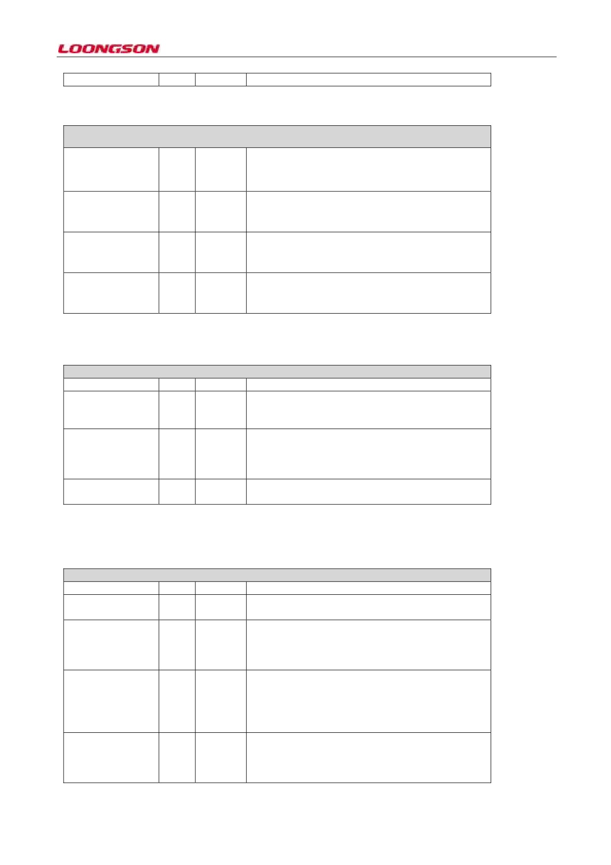
Reserved
4:0
0x0
Reserved
11.2.20 Register52 (Auto-Negotiation Expansion Register)
Register52 (Auto-Negotiation Expansion Register)Offset: 0x0D
Reserved
31:3
0x0
Reserved
NPA: Next Page2
0x0
It’s only read to 0, because MAC doesn’t support the
Ability
next page.
NPR: New Page1
0x0
When the bit is 1, it indicates that MAC receives the
Received
new page.
Reserved
0
0x0
Reserved
11.2.21 Register54 (SGMII/RGMII Status Register)
Register54 (SGMII/RGMII Status Register)Offset: 0x0D
Reserved
31:4
0x0
Reserved
Link Status
3
0x0
When this bit is set to
1, indicating the link is
connected. When this bit is set to 0, indicating the link
is disconnected.
Link Speed
2:1
0x0
Indicate current link speed
00: 2.5MHz
01: 25MHz
10: 125MHz
Link Mode
0
0x0
0: Half-duplex
1: Full-duplex
IEEE1588 register:
11.2.22 Register448 (Time Stamp Control Register)
Register448 (Time Stamp Control Register)Offset: 0x0700
Reserved
31:20
0x0
Reserved
ATSFC: Auxiliary19
0x0
When the bit is
1, reset the pointer of Auxiliary
SnapshotFIFO Clear
Snapshot FIFO, clear FIFO. After this, the bit is 0.
TSENMACADDR:
18
0x0
When the bit is 1, the received PTP package will go
EnableMAC
through the MAC destination address filter (DA Fiter)
addressfor PTP frame
in MAC, and the mismatching PTP packet will be
filtering
abandoned.
TSCLKTYPE: Select17:16
0x0
The domain is coded according to the following types:
the type of clock
00: Ordinary clock
node
01: Boundary clock
10: End-to-End Transparent clock
11: Peer-to-peer Transparent clock
TSMSTRENA:
15
0x0
When the bit is 1, Snapshot records messages Relevant
Enable Snapshot for
to Master; when the bit is 0, Snapshot records messages
Messages Relevant to
Relevant to Slave.
Master
-74-

TSEVNTENA:
14
0x0
When the bit is 1, Snapshot only records the Event
Enable Time Stamp
Message; when the bit is
0, Snapshot records all
Snapshot for Event
messages.
Messages
TSIPV4ENA: Enable13
0x0
When the bit is 1, the Time Stamp Snapshot of IPv4
TimeStamp Snapshot
frame is enabled.
for IPv4 frames
TSIPV4ENA: Enable12
0x0
When the bit is 1, the time stamp snapshot of IPv6
TimeStamp Snapshot
frame is enabled.
for IPv4 frames
TSIPENA:Enable
11
0x0
When the bit is 1, the PTP packet (PTP over Ethernet)
TimeStamp Snapshot
in the format of Ethernet enables Time Stamp
for PTP overEthernet
Snapshot; when the bit is 0, the PTP packet in the
frames
format of UDP-IP-Ethernet enables Time Stamp
Snapshot.
TSCTRLSSR: Time9
0x0
When the bit is 1, Time Stamp Low register updates
Stamp Digital or
and adds the time stamp after its value exceeds
Binary
rollover
0x3B9A_C9FF; when the bit is 0, the Time Stamp Low
control
register is reset to 0x7FFF_FFFF.
TSENALL: Enable8
0x0
When the bit is 1, it indicates that all frames received
Time Stamp for All
by MACs enable the time stamp.
Frames
Reserved
7:6
0x0
Reserved
TSADDREG:
5
0x0
When the bit is 1, the value of Time Stamp Addend
Addend Reg Update
register is used to update PTP block for fine correction.
When the updating finishes, this bit is 0.
TSTRIG:
Time4
0x0
When the bit is 1, if the system time is larger than the
Stamp
Interrupt
value of Target Time register, one time stamp interrupt
Trigger Enable
is generated; after the generation of interrupt, this bit is
reset to 0.
TSUPDT:
Time
3
0x0
When the bit is 1, based on the values of Time Stamp
Stamp Update
High Update and Time Stamp Low Update registers,
the system updates the current system time, and after
this the bit is 0.
TSINIT: Time Stamp2
0x0
When the bit is 1, based on the values of Time Stamp
Initialize
High Update and Time Stamp Low Update registers,
the system initializes the current system time, and after
this the bit is 0.
TSCFUPDT: Time1
0x0
When the bit is 1, it indicates that the Time Stamp will
Stamp Fineor Coarse
adopt the Fine Update, and when the bit is
0, it
Update
indicates that the Time Stamp will use Coarse.
Time Stamp Fineor
Coarse updating
TSENA: Time Stamp1
0x0
When the bit is 1, it indicates the receive and transmit
Enable
frame systems will enable the Time Stamp record;
when the bit is 0, it indicates the Time Stamp record is
stopped for receive and transmit frames, and the Time
Stamp generator is paused; after the bit is set to 1, the
Time Stamp Initialization starts (bit 2).
11.2.23 Register449 (Sub-Second Increment Register)
Register449 (Sub-Second Increment Register)Offset: 0x0704
Reserved
31:8
0x0
Reserved
SSINC: Sub-second7:0
0x0
The value in this domain will be added to sub-second
increment value
register
-75-
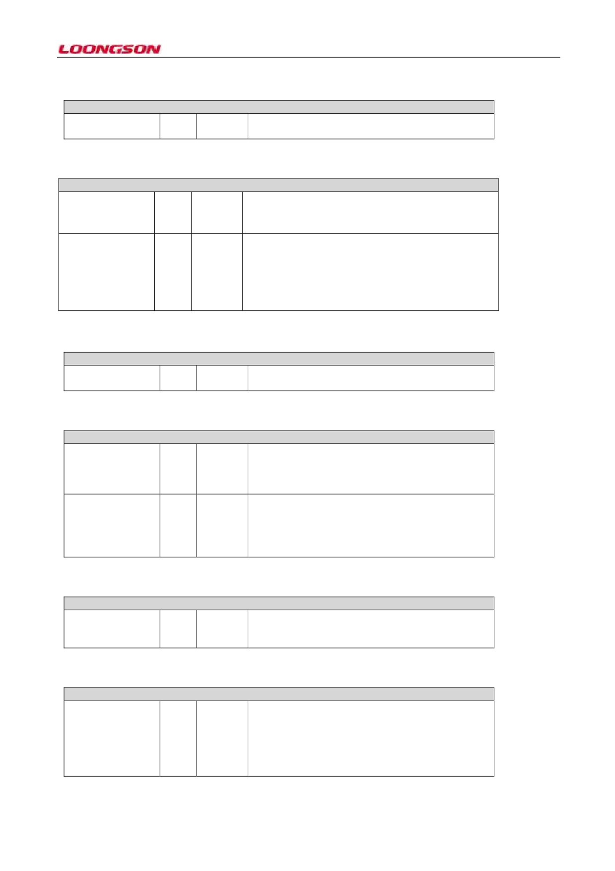
11.2.24 Register 450 (System Time - Seconds Register)
Register 450 (System Time - Seconds Register)Offset: 0x0708
TTSS: Time Stamp31:0
0x0
The value of this domain indicates the second count of
Second
the current system time
11.2.25 Register 451 (System Time - Nanoseconds Register)
Register 451 (System Time - Nanoseconds Register) Offset: 0x0C
31
0x0
This domain indicates the positive or negative time. When
PSNT: Positive or
the bit is 1, it indicates the time is positive. When the bit is
Negative Time
0, it indicates the time is negative.
30:0
0x0
The value of this domain indicates the sub-second count
TSSS: Time Stamp Sub
Seconds
of the current system time, and time precision is 0.46
nanosecond by default (when the TSCTRLSSR asserts the
start precision to 1ns,
the maximum is 0x3B9A_C9FF)
11.2.26 Register 452 (System Time - Seconds Update Register)
Register 452 (System Time - Seconds Update Register)Offset: 0x0710
TTSS: Time Stamp31:0
0x0
The value of this domain is the initial value of system
Second
initialization or the increment in updating
11.2.27 Register 453 (System Time - Nanoseconds Update Register)
Register 453 (System Time - Nanoseconds Update Register)Offset: 0x0714
ADDSUB:Add or31
0x0
This domain indicates adding or subtracting time.
subtract time
When the bit is 1, it indicates the updated register value
is subtracted in updating. When the bit is 0, it indicates
the updated register value is added.
TSSS: Time Stamp
30:0
0x0
The value of this domain indicates the sub-second
Sub Seconds
count is added or reduced when the current system time
updates, and the time precision is 0.46 nanosecond by
default (when the TSCTRLSSR sets the start precision
to 1ns, the maximum is 0x3B9A_C9FF)
11.2.28 Register 454 (Time Stamp Addend Register)
Register 454 (Time Stamp Addend Register)Offset: 0x0718
31:0
0x0
The value of this domain indicates that the 32bit time
TAR: Time Stamp
value to add in system time synchronization
Addend Register
11.2.29 Register 455 (Target Time Seconds Register)
Register 455 (Target Time Seconds Register)Offset: 0x1C
TSTR: Target Time31:0
0x0
This domain has saved the time in the unit of second.
Seconds Register
When the time stamp time matches or exceeds the
value of this field and low bit register (reg 456) and
includes MAC address matching, the system will
generate an interrupt (the interrupt must be enabled in
advance)
-76-
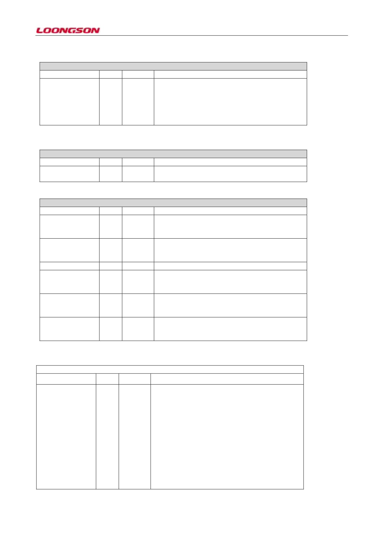
11.2.30 Register 456 (Target Time Nanoseconds Register)
Register 456 (Target Time Nanoseconds Register)Offset: 0x02
Reserve
31
0x0
TSTR: Target Time30:0
0x0
This domain has saved the time in the unit of second.
Stamp Low Register
When the time stamp time matches or exceeds the
value of this field and low bit register (reg 455) and
includes MAC address matching, the system will
generate an interrupt (the interrupt must be enabled in
advance)
11.2.31 Register 457 (System Time - Higher Word Seconds Register)
Register 457 (System Time - Higher Word Seconds Register)Offset: 0x24
Reserve
31:16
0x0
TSHWR:Time Stamp15:0
0x0
This domain saves the time stamp of high 16bit (most
Higher Word Register
significant bit)
11.2.32 Register 458 (Time Stamp Status Register)
Register 458 (Time Stamp Status Register)Offset: 0x02
Reserve
31:28
0x0
ATSNS:Auxiliary
27:25
0x0
This domain indicates the number of snapshots in
Time Stamp Number
FIFO, 4(3`b100) FIFO full, and 0(3`000) FIFO empty
of Snapshots
ATSSTM: Auxiliary24
0x0
When the bit is 1, it indicates the current FIFO is full
Time Stamp Snapshot
and has set the external trigger, and the last snapshot is
Trigger Missed
missed because of FIFO full; or, it’s 0.
Reserve
23:3
0x0
AuxiliaryTime
2
0x0
When the bit is 1, it indicates the snapshot is written to
StampTrigger
FIFO.
Snapshot
TSTARGT:Time
1
0x0
When the bit is 1, the system time has exceeded or is
Stamp Target Time
equal to the value of target time stamp register
Reached
TSSOVF:Time
0
0x0
When the bit is 1, it indicates the time of the current
StampSeconds
time
stamp has overflowed
(larger
than
Overflow
0xFFFF_FFFF); or, it’s 0.
11.2.33 Register 459 (PPS Control Register)
Register 459 (PPS Control Register)Offset: 0x0C
31:4
0x0
Reserve
PPSCTRL: Control the
15:0
0x0
This domain sets the time interval of two PPS signals
output, and is encoded as follows
duration
between
0000: 1.0s (Binary & Digital Rollover)
2-pulses of PPS signa
0001: 0.5s (Binary Rollover) , 0.536s (Digital
output
Rollover)
0010: 0.25 s (Binary Rollover) , 0.26s (Digital
Rollover)
0011: 0.125 s (Binary Rollover) , 0.26s (Digital
Rollover)
…..
-77-