Boeing 737 - 600/700/800/900. Operations Manual (1997 year) - page 53
Flight Instruments, Displays -
Navigation Displays
Boeing 737 Operations Manual
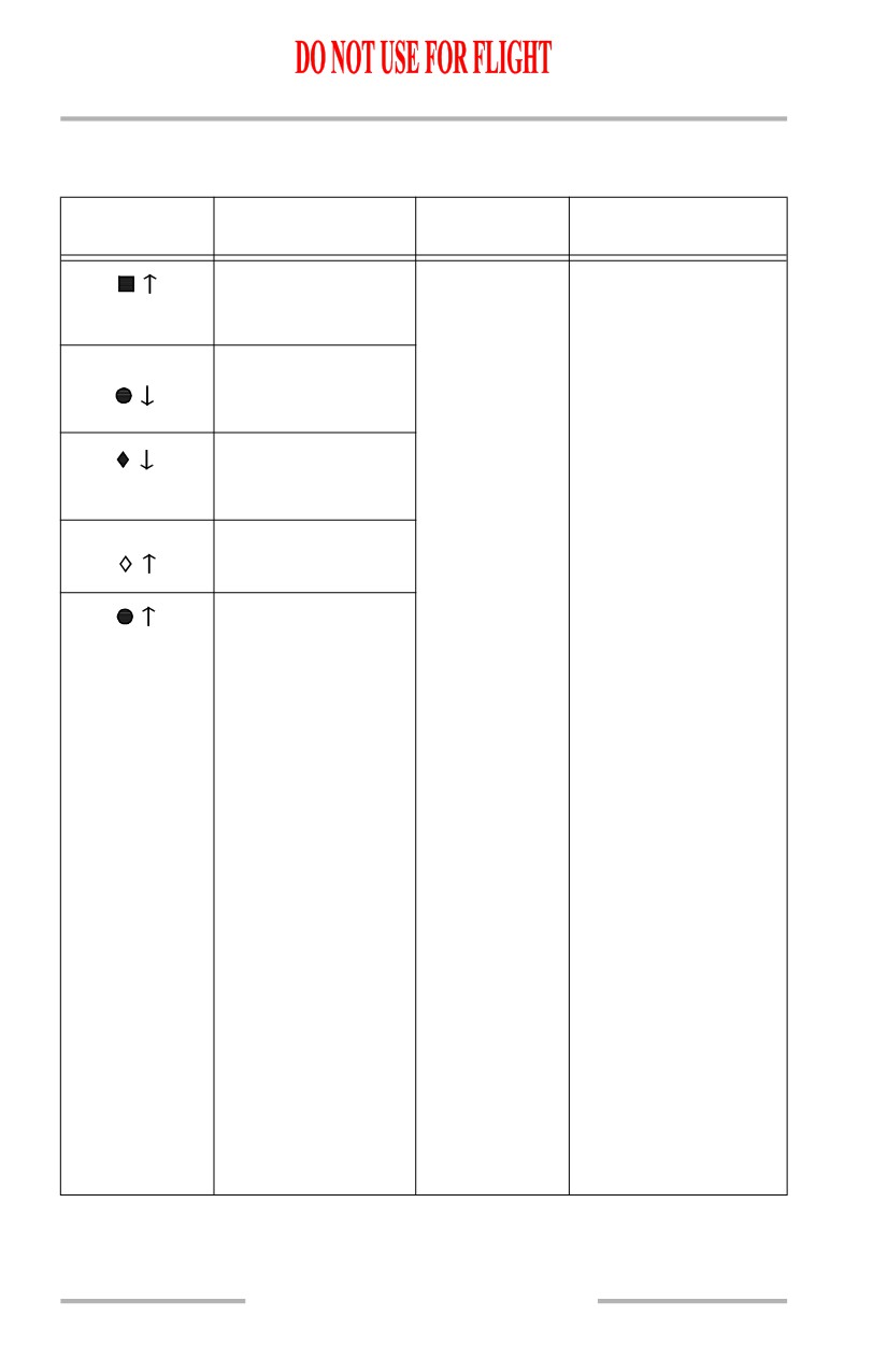
TCAS
[Option - 3NM TCAS range ring]
SYMBOL
NAME
APPLICABLE
REMARKS
MODE(S)
TCAS resolution
MAP,
These symbols are
advisory (RA),
MAP CTR,
displayed only when the
-03
relative altitude (R)
APP,
EFIS control panel
VOR
traffic (TFC) switch is
TCAS traffic advisory
+02
selected on. Refer to
(TA), relative altitude
Chapter 15, Warning
(A)
Systems.
TCAS proximate
The arrow indicates
traffic, relative
traffic climbing or
-05
altitude (W)
descending at a rate
greater than or equal to
TCAS other traffic,
+09
500 fpm. At rates less
relative altitude (W)
than 500 fpm, the arrow
TCAS TA, absolute
is not displayed.
12 8
altitude
For relative altitude
symbols, the number
and related signs
indicate altitude of
traffic in hundreds of
feet relative to the
airplane.
For absolute altitude
symbols, the number
indicates altitude of
traffic in thousands and
hundreds of feet.
For both relative and
absolute altitude, the
number is below the
traffic symbol when the
traffic is below, and
above the traffic symbol
when the traffic is above
the airplane. Absence of
the number implies
altitude unknown.
10.40.18

Flight Instruments, Displays -
Navigation Displays
Boeing 737 Operations Manual
SYMBOL
NAME
APPLICABLE
REMARKS
MODE(S)
RA 5.3 +03
TCAS no bearing
MAP,
Message provides traffic
message (RA-R,
MAP CTR,
type, range in NM,
TA 8.9 -12
TA-A)
APP,
altitude and vertical
VOR
direction.
Range Ring (W)
MAP,
Displayed when TFC
MAP CTR,
selected on EFIS
APP,
Control Panel. Shows 3
VOR
NM range ring oriented
to aircraft heading.
Displayed at ranges of
80 NM or less.
TCAS traffic alert
All
Displayed whenever a
TRAFFIC
message (RA-R,
TCAS RA or TA is
TA-A)
active. EFIS control
panel TFC switch does
not have to be selected
on.
TCAS off scale
MAP,
Displayed whenever RA
OFFSCALE
message (RA-R,
MAP CTR,
or TA traffic is outside
TA-A)
APP,
the traffic area covered
VOR
by the selected range.
Displayed only if the
EFIS control panel TFC
switch is selected on.
TCAS mode (C)
MAP,
Indicates the TCAS
TFC
MAP CTR,
display is active; the
APP,
EFIS control panel TFC
VOR
switch is selected on.
TCAS mode (C)
All
Indicates TCAS
TA ONLY
computer is not
computing RAs.
Displayed whether the
EFIS control panel TFC
switch is selected on or
off.
10.40.19

Flight Instruments, Displays -
Navigation Displays
Boeing 737 Operations Manual
SYMBOL
NAME
APPLICABLE
REMARKS
MODE(S)
TCAS mode (C)
All
Indicates TCAS is
TCAS TEST
operating in the test
mode. Displayed
whether EFIS control
panel TFC switch is
selected on or off.
TCAS mode (A)
All
Displayed when the
TCAS
TCAS/ATC mode
OFF
switch is not in TA
ONLY or TA/RA,
whether EFIS control
panel TFC switch is
selected on or off. Not
displayed if TCAS is
failed or in test.
TCAS mode (A)
All
Indicates TCAS failure,
TCAS
whether EFIS control
FAIL
panel TFC switch is
selected on or off. Once
displayed, can be cycled
on/off with the TFC
switch.
10.40.20
Boeing 737 Operations Manual
Flight Instruments, Displays
Chapter 10
PFD/ND Navigation Displays
Section 41
Introduction
The NDs provide a mode-selectable color flight progress display. The modes are:
• MAP
• APP (approach)
• VOR
• PLN (plan).
The MAP, VOR, and APP modes can be switched between an expanded mode
with a partial compass rose and a centered mode with a full compass rose.
Map Mode
The MAP mode is recommended for most phases of flight.
[Option - Track-up display]
Presented track up, this mode shows airplane position relative to the route of flight
against a moving map background.
Displayed information can include:
• current track
• true airspeed
• selected and current heading
• wind direction and speed
• position trend vector
• next waypoint distance
• range to selected altitude
• waypoint estimated
• map range scale
time of arrival
• ground speed
• selected navigation data points.
Navigation Data Points
Additional navigation facility (STA), waypoint (WPT), airport (ARPT), route
progress (DATA) and position (POS) data are available for display on the ND in
both the expanded and center map modes.
VOR and Approach Modes
The VOR and APP modes are presented heading up. The VOR and APP modes
display track, heading, and wind speed and direction with VOR navigation or ILS
approach information.
Plan Mode
The PLN mode is presented true north up. The active route may be viewed using
the STEP prompt on the CDU LEGS pages.
10.41.1
Flight Instruments, Displays -
PFD/ND Navigation Displays
Boeing 737 Operations Manual
ND Information
Heading
Heading is supplied by the FMC or air data inertial reference system (ADIRS).
The ND compass rose can be referenced to magnetic north or true north.
Track
Track is supplied by the FMC during normal operation.
Traffic
Traffic information from the TCAS can be displayed on the ND. TCAS is
described in Chapter 15, Warning Systems.
Weather Radar
Weather radar information can be displayed on the ND. The weather radar system
is described in Chapter 11, Flight Management, Navigation.
Failure Flags and Messages
Failure flags are displayed for system failures or invalid information. Indications
are removed or replaced by dashes when source system information is not
available.
The message EXCESS DATA is displayed if the amount of information sent to the
ND exceeds the display capability. When this occurs, the primary display system
removes information from the outer edge of the display. The message can be
removed by:
• reducing the amount of map information
• reducing range, or
• deselecting one or more of the EFIS control panel map switches (STA,
WPT, ARPT, DATA, POS).
ND Symbology
The following symbols can be displayed on each ND, depending on EFIS control
panel switch selections. Colors indicate the following:
• W (white) - present status, range scales
• G (green) - dynamic conditions
• M (magenta) - command information, pointers, symbols, fly-to condition
• C (cyan) - nonactive or background information
• A (amber) - cautions, faults, flags
• R (red) - warnings
• B (black) - blank area, off condition.
10.41.2
Flight Instruments, Displays -
PFD/ND Navigation Displays
Boeing 737 Operations Manual
Heading, Track, and Speed
[Option - Track-up display]
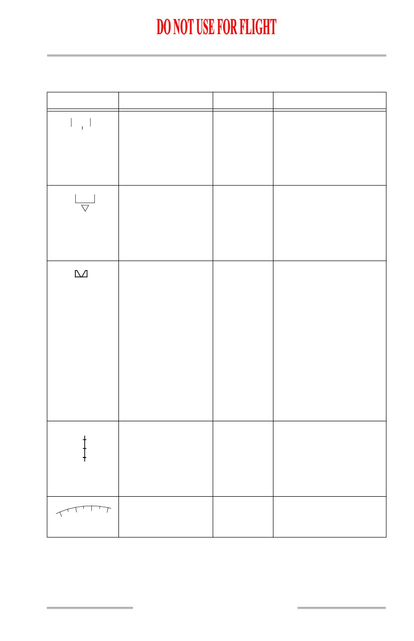
SYMBOL
NAME
ND MODE
REMARKS
Track orientation (G),
Shows track
Displays TRK as the
TRK
062
MAG
current track (W), and
in MAP,
orientation, the current
track reference (G)
MAP CTR.
track, and MAG or TRU as
the reference, and points to
the heading on the compass
rose.
Heading orientation
Shows HDG
Displays HDG as the
HDG
263
MAG
(G), current heading
(heading) in
display orientation, current
(W), heading
VOR,
heading, MAG or TRU as
reference (G), and
VOR CTR,
the heading reference, and
heading pointer (W)
APP,
points to the heading on the
APP CTR
compass rose.
Selected heading bug
All except
Displays the MCP-selected
(M)
PLAN
heading. A dashed
reference line (M) extends
from the marker to the
airplane symbol (VOR
CTR and APP CTR do not
display dashed line).
In the MAP mode with
LNAV or VORLOC
engaged, the dashed line is
removed 10 seconds after
the selected heading bug is
moved.
Track line and range
MAP,
Indicates current track.
scale (W)
MAP CTR,
Number indicates range
40
VOR,
(VOR CTR and APP CTR
VOR CTR,
do not display range).
APP,
APP CTR
Expanded compass
MAP,
Displays 90 degrees of
15
(W)
APP,
compass rose.
12
VOR
10.41.3

Flight Instruments, Displays -
PFD/ND Navigation Displays
Boeing 737 Operations Manual
SYMBOL
NAME
ND MODE
REMARKS
Groundspeed (W)
All
Current ground speed.
GS310
True airspeed (W)
All
Current true airspeed
TAS312
displayed above 100 knots.
Wind direction/ speed
All
Indicates wind speed and
350 /15
and wind arrow (W)
direction, with respect to
display orientation and
heading/track reference.
Displayed if wind
magnitude is greater than 6
knots and blanked if wind
magnitude becomes less
than 4 knots. Blank until
TAS is greater than 101
knots. PLAN mode
displays speed/direction
only.
10.41.4
Flight Instruments, Displays -
PFD/ND Navigation Displays
Boeing 737 Operations Manual
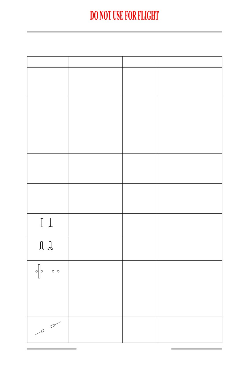
Radio Navigation
[Option - VOR course lines displayed, dual ADF]
SYMBOL
NAME
ND MODE
REMARKS
Reference receiver (G)
VOR,
Indicates the selected
VOR 1, 2
ILS 1, 2
VOR CTR,
receiver as the display
APP,
reference.
APP CTR
ILS/VOR (W)
VOR,
Located upper right corner.
116.80
OR
Reference receiver
VOR CTR,
Frequency displayed before
SEA
frequency or identifier
APP,
the identifier is decoded.
display
APP CTR
The decoded identifier
replaces the frequency.
Medium size characters for
VOR, small size characters
for DME only.
Reference ILS or
VOR,
Located upper right corner.
DME 24.6
VOR DME (W)
VOR CTR,
Indicates DME distance to
APP,
the reference navaid.
APP CTR
Reference ILS or
VOR,
Located upper right corner.
CRS
135
VOR course (W)
VOR CTR,
Indicates the VOR course
APP,
or ILS localizer course.
APP CTR
VOR 1 (G) or ADF 1
All except
Indicates bearing to (head)
(C) pointer head and
PLAN
or from (tail) the tuned
tail
station, if selected on the
respective EFIS control
VOR 2 (G) or ADF 2
panel.
(C) pointer head and
tail
ILS localizer or VOR
VOR,
Displays LOC or VOR
course deviation
VOR CTR,
course deviation. Deviation
indication (M) and
APP,
indicator points in direction
scale (W)
APP CTR
of VOR or ILS selected
course. For ILS deviation,
indicator fills (M) when
less than 2 1/2 dots from
center.
Selected course
VOR,
Displays selected course as
pointer (W) and line
APP,
set by the related MCP
(M)
course selector.
10.41.5
Flight Instruments, Displays -
PFD/ND Navigation Displays
Boeing 737 Operations Manual
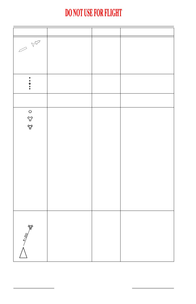
SYMBOL
NAME
ND MODE
REMARKS
Selected course
APP CTR,
Displays selected course as
pointer (W)
VOR CTR
set by the related MCP
course selector.
TO/FROM pointer
(W)
TO/FROM pointer is
displayed when VOR
navigation is being used.
Glide slope pointer
APP,
Displays glideslope
(M) and scale (W)
APP CTR
position and deviation.
To/from indication
VOR,
Displays VOR to/from
TO
FROM
(W)
VOR CTR
indication.
VOR (C, G),
MAP,
When the EFIS control
MAP CTR,
panel STA map switch is
DME/TACAN (C, G),
PLN
selected on, appropriate
VORTAC (C, G)
navaids are displayed. All
navaids contained in the
FMC data base and within
the MAP area are displayed
when the selected range is
5, 10, 20 or 40 nm. Only
high altitude navaids are
displayed when the selected
range is 80, 160, 320 or 640
nm. Nav aids not being
used are displayed in cyan.
Manually tuned VHF
navaids are displayed in
green, regardless of STA
map switch selection.
VOR/DME raw data
MAP,
When the POS map switch
radial and distance (G)
MAP CTR
is selected on, the station
radial extends to the
airplane.
10.41.6

Flight Instruments, Displays -
PFD/ND Navigation Displays
Boeing 737 Operations Manual
SYMBOL
NAME
ND MODE
REMARKS
Manually tuned VOR
MAP,
When a navaid is manually
radials
MAP CTR,
tuned, the selected course
PLN
and reciprocal are
displayed.
VOR (G) or ADF (C)
MAP,
Located lower left or right
VOR 1, 2
ADF 1, 2
selection
MAP CTR,
corner. Represents
VOR,
positions of the EFIS
VOR CTR,
control panel VOR/ADF
APP,
switches.
APP CTR
VOR frequency or
MAP,
Located lower left or right
116.80
OR
identifier (G),
MAP CTR,
corner. Frequency is
SEA
OR
VOR,
displayed before identifier
520
ADF frequency or
OR
VOR CTR,
is decoded. Decoded
identifier (C)
BF
APP,
identifier replaces the
APP CTR
frequency. For VORs,
small size characters
indicate only DME
information is being
received.
DME distance (G)
MAP,
Located lower left or right
DME24.6
MAP CTR,
corner. Indicates DME
VOR,
distance to navaid.
VOR CTR,
APP,
APP CTR
October 15, 2001
10.41.7
Flight Instruments, Displays -
PFD/ND Navigation Displays
Boeing 737 Operations Manual
Map
[Option - Weather radar range arcs, dual FMC]
SYMBOL
NAME
ND MODE
REMARKS
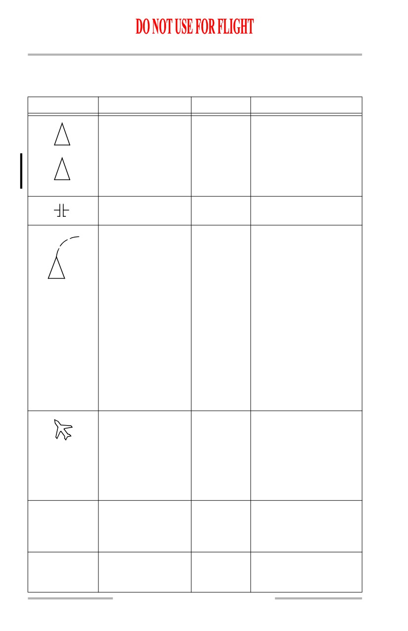
Airplane symbol (W)
MAP,
Current airplane position is
MAP CTR,
at the apex of the triangle.
VOR,
APP
Current airplane position
MAP,
with lateral path deviation
1.2 R
MAP CTR.
distance.
Airplane symbol (W)
VOR CTR,
Current airplane position is
APP CTR
at the center of the symbol.
Position trend vector
MAP,
Predicts position at the end
(W) (dashed line)
MAP CTR
of 30, 60, and 90 second
intervals. Each segment
represents 30 seconds.
Based on bank angle and
ground speed. Selected
range determines the
number of segments
displayed. For range:
• greater than 20
NM, 3 segments
•
= 20 NM, 2
segments
•
< = 10 NM, 1
segment.
Airplane symbol (W)
PLAN
Indicates actual position
and track along the flight
plan route in plan mode
only.
Inhibited north of 82N
latitude and south of 82S
latitude.
Active waypoint
MAP,
Indicates the active flight
ABCDE
identifier (M)
MAP CTR,
plan waypoint, the next
PLAN
waypoint on the route of
flight.
Active waypoint
MAP,
Distance to the active
124 NM
distance (W)
MAP CTR,
waypoint.
PLAN
10.41.8
Flight Instruments, Displays -
PFD/ND Navigation Displays
Boeing 737 Operations Manual
SYMBOL
NAME
ND MODE
REMARKS
Active waypoint ETA
MAP,
Indicates FMS-calculated
0835.4z
(W)
MAP CTR,
ETA at the active waypoint.
PLAN
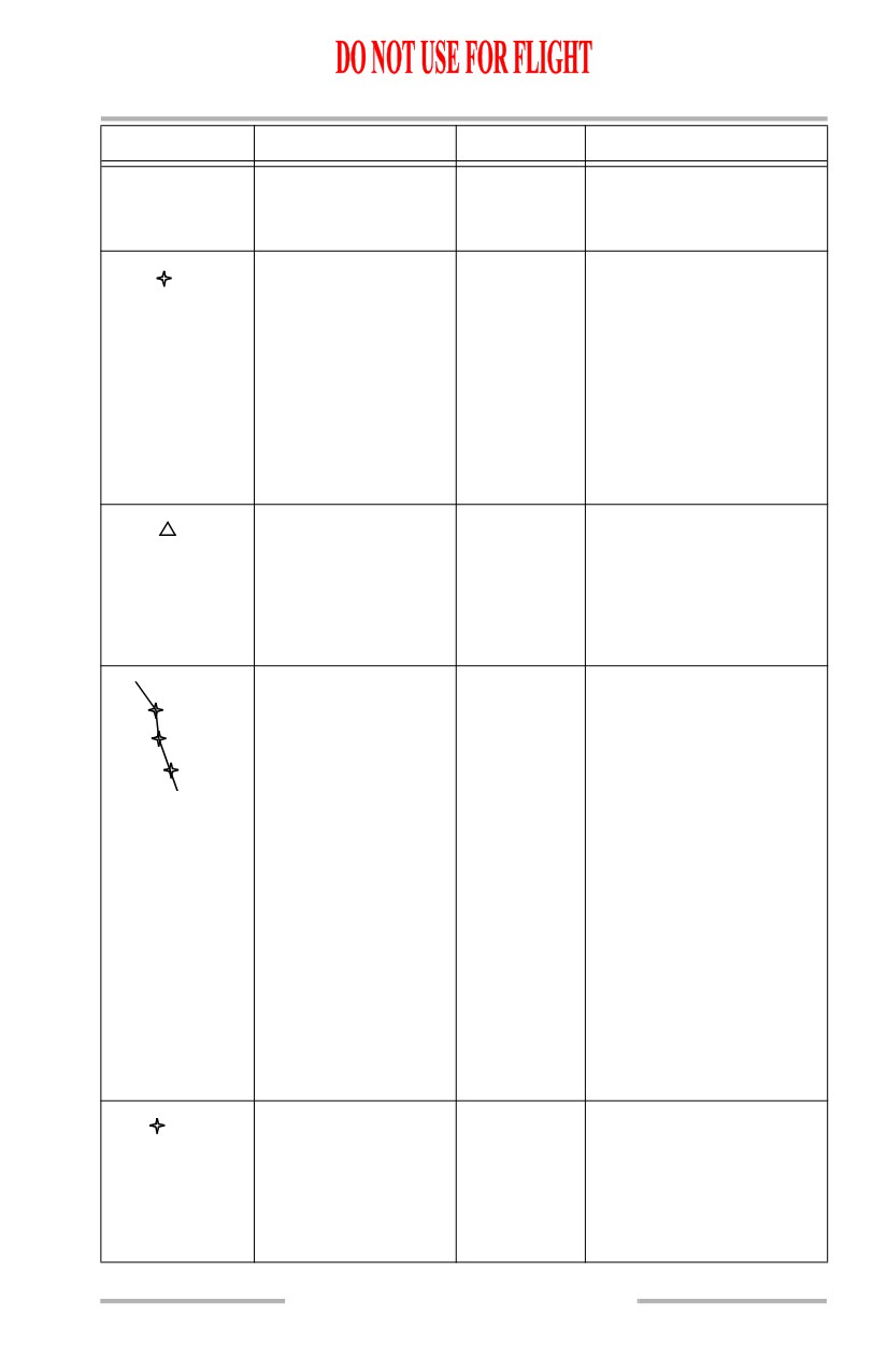
Waypoint: active (M),
MAP,
Active - represents the
modified (W), inactive
MAP CTR,
waypoint the airplane is
AMBOY
(C)
PLAN
currently navigating to.
Modified - represents
modified waypoints on the
active route.
Inactive - represents the
waypoints on the active
route.
Off route waypoint
MAP,
When the EFIS control
MLF
(C)
MAP CTR,
panel WPT map switch is
PLAN
selected on, waypoints not
on the selected route are
displayed, in ND ranges of
5, 10, 20, or 40.
Flight plan route:
MAP,
The active route is
AMBOY
active (M), modified
MAP CTR,
displayed with a continuous
KILMR
(W), inactive (C),
PLAN
line (M) between
offset (M)
waypoints.
PARBY
Active route modifications
are displayed with short
dashes (W) between
waypoints.
Inactive routes are
displayed with long dashes
between waypoints.
An offset route, selected
through the FMC, is
displayed with a dot-dash
line (M) parallel to the
active route.
Route data: active
MAP,
When the EFIS control
KILMR
12000
waypoint (M),
MAP CTR,
panel DATA switch is
0835Z
inactive waypoint (W)
PLAN
selected on, entered or
procedural altitude and
ETAs for route waypoints
are displayed.
October 15, 2001
10.41.9
Flight Instruments, Displays -
PFD/ND Navigation Displays
Boeing 737 Operations Manual
SYMBOL
NAME
ND MODE
REMARKS
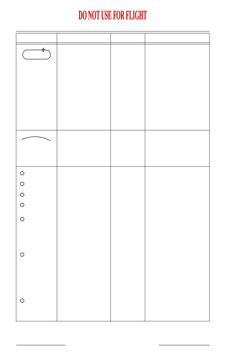
Holding pattern:
MAP,
A holding pattern appears
active route (M),
MAP CTR,
when in the flight plan.
modified route (W),
PLAN
The holding pattern appears
inactive route (C)
as a fixed size if the
selected range is greater
than 80 NM.
A scaled representation of
the holding pattern is
displayed when the selected
range is 80 NM or less and
the airplane is within 3
minutes of the holding fix.
Altitude range arc (G)
MAP,
Based on vertical speed and
MAP CTR,
groundspeed, indicates the
approximate map position
where the MCP altitude
will be reached.
Altitude profile point
MAP,
Indicates the approximate
and identifier (G)
MAP CTR,
map position of the
T/D
PLAN
FMC-calculated T/C
T/C
(top-of-climb), T/D (top-
of-descent), S/C (step
S/C
climb), and E/D (end of
E/D
descent) points.
Indicates intermediate T/D
T/D-XXXXX
points for level flight path
segments during descent.
Level flight path segment
altitude is displayed.
Indicates the beginning of a
DECEL
deceleration segment
resulting from deceleration
to a holding pattern, a
waypoint speed restriction
or flaps up maneuvering
speed.
Indicates airport speed
restriction deceleration
point (no identifier).
10.41.10
Flight Instruments, Displays -
PFD/ND Navigation Displays
Boeing 737 Operations Manual
SYMBOL
NAME
ND MODE
REMARKS
VNAV path pointer
MAP,
Displays vertical deviation
(M) and deviation
MAP CTR
from selected VNAV PATH
scale (W)
during descent only. Scale
indicates ± 400 feet
VNAV path deviation
deviation. Digital display is
band (M)
provided when the pointer
indicates more than ± 400
feet.
Path deviation band is
symmetric about the
pointer and represents
vertical RNP.
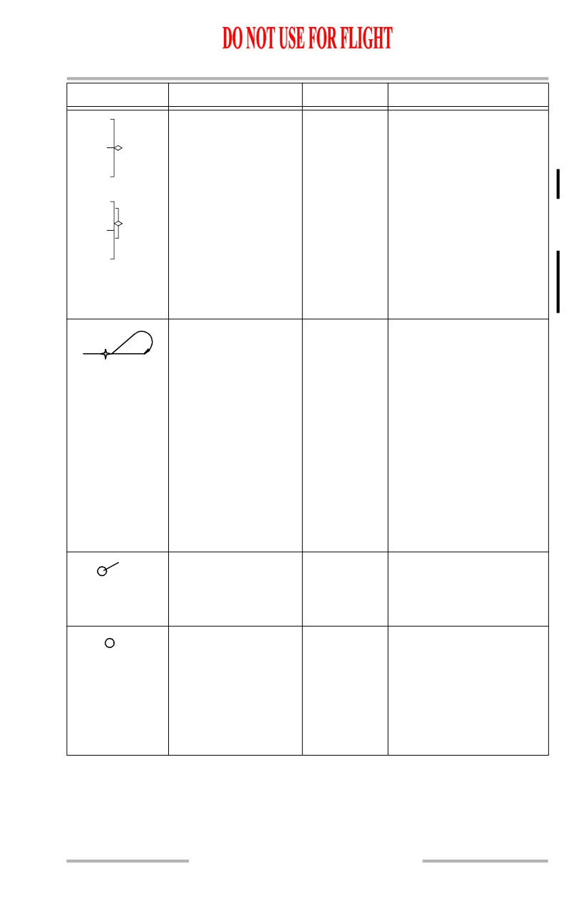
Procedure turn: active
MAP,
A procedure turn appears
route (M), modified
MAP CTR,
when in the flight plan.
route (W), inactive
PLAN
The procedure turn appears
route (C)
as a fixed size if the
selected range is greater
than 80 NM.
A scaled representation of
the procedure turn is
displayed when the selected
range is 80 NM or less and
the airplane is within 3
minutes of the procedure
turn.
Airport and runway
MAP,
Displayed when selected as
KABC
(W)
MAP CTR,
the origin or destination
22L
PLAN
and ND range is 80, 160,
320, or 640 NM.
Airport (C)
MAP,
Displayed if the EFIS
KTEB
MAP CTR,
control panel ARPT map
PLAN
switch is selected on.
Origin and destination
airports are always
displayed, regardless of
map switch selection.
10.41.11
Flight Instruments, Displays -
PFD/ND Navigation Displays
Boeing 737 Operations Manual
SYMBOL
NAME
ND MODE
REMARKS
Airport and runway
MAP,
Displayed when selected as
(W)
MAP CTR,
the origin or destination
22L
PLAN
and ND range is 5, 10, 20,
or 40 NM. Dashed runway
centerlines extend 14.2
NM.
Selected reference
MAP,
Displays the reference
point and bearing
MAP CTR,
point selected on the CDU
distance information
PLAN
FIX page. Bearing and/or
ABC
(G)
distance from the fix are
displayed with dashes (G).
MAP source
MAP,
Displays source of FMC
FMC L
annunciation (G)
MAP CTR,
data used by CDS for data
FMC R
FMC
PLN
presentation. If single FMC
installed, displays FMC.
GPS position (W)
MAP,
When the EFIS POS map
MAP CTR
switch is selected on,
indicates GPS position
relative to FMC position.
ADIRU position (W)
MAP,
When the EFIS control
MAP CTR
panel POS map switch is
selected on, the star
indicates ADIRU position
relative to FMC position.
Weather radar returns
MAP,
The most intense areas are
(R, A, G, M)
MAP CTR,
displayed in red, lesser
VOR, APP
intensity in amber, and
lowest intensity green.
Turbulence is displayed in
magenta.
Selected map options
MAP,
Displays EFIS control
STA
WPT
(C)
MAP CTR,
panel selected map options.
ARPT
PLAN
10.41.12

Flight Instruments, Displays -
PFD/ND Navigation Displays
Boeing 737 Operations Manual
SYMBOL
NAME
ND MODE
REMARKS
North up arrow (G)
PLAN
Indicates map background
N
is oriented and referenced
to true north.
Range arcs (W)
MAP,
Displayed in MAP, APP
APP,
and VOR modes when the
VOR
EFIS WXR map switch is
selected or TCAS TFC
switch is selected.
Weather radar
MAP,
Annunciations vary with
WXR
annunciations
MAP CTR,
option selected
+5
VOR,
CAL or VAR
Mode (C), Tilt (C)
APP
Gain (C)
10.41.13

Flight Instruments, Displays -
PFD/ND Navigation Displays
Boeing 737 Operations Manual
Look-Ahead Terrain
SYMBOL
NAME
ND MODE
REMARKS
Terrain display (R, A,
MAP,
Displays terrain data from
G, M)
MAP CTR,
the GPWS terrain data
APP,
base.
VOR
Terrain 2000 feet below to
500 feet (250 feet with gear
down) below the airplane’s
current altitude (G), terrain
500 feet (250 feet with gear
down) below to 2000 feet
above the airplane’s current
altitude (A), terrain more
than 2000 feet above
airplane’s current altitude
(R), no terrain data
available (M).
Color and density vary
based on terrain height vs.
airplane altitude.
Terrain mode
MAP,
Terrain display enabled
TERR
annunciation (C)
MAP CTR,
(manual or automatic
APP,
display).
VOR
Terrain test mode
All
GPWS operating in
TERR
annunciation (C)
self-test mode.
TEST
Terrain annunciation
All
Look-ahead terrain caution
TERRAIN
(R, A)
alert active (A), look-ahead
terrain warning alert active
(R).
10.41.14

Flight Instruments, Displays -
PFD/ND Navigation Displays
Boeing 737 Operations Manual
SYMBOL
NAME
ND MODE
REMARKS
Terrain status
All
Look-ahead terrain alerting
TERR FAIL
annunciations (A)
and display have failed.
All
Look-ahead terrain alerting
TERR POS
and display unavailable due
to position uncertainty.
All
GPWS terrain inhibit
TERR INHIBIT
switch in TERR INHIBIT
position.
Terrain range status
MAP,
Terrain output range
TERR RANGE
annunciations (A)
MAP CTR,
disagrees with selected
DISAGREE
APP,
EFIS control panel range.
VOR
MAP,
Terrain output range and
MAP/TERR
MAP CTR
map display output range
RANGE
disagree with selected EFIS
DISAGREE
control panel range.
10.41.15

Flight Instruments, Displays -
PFD/ND Navigation Displays
Boeing 737 Operations Manual
Predictive Windshear
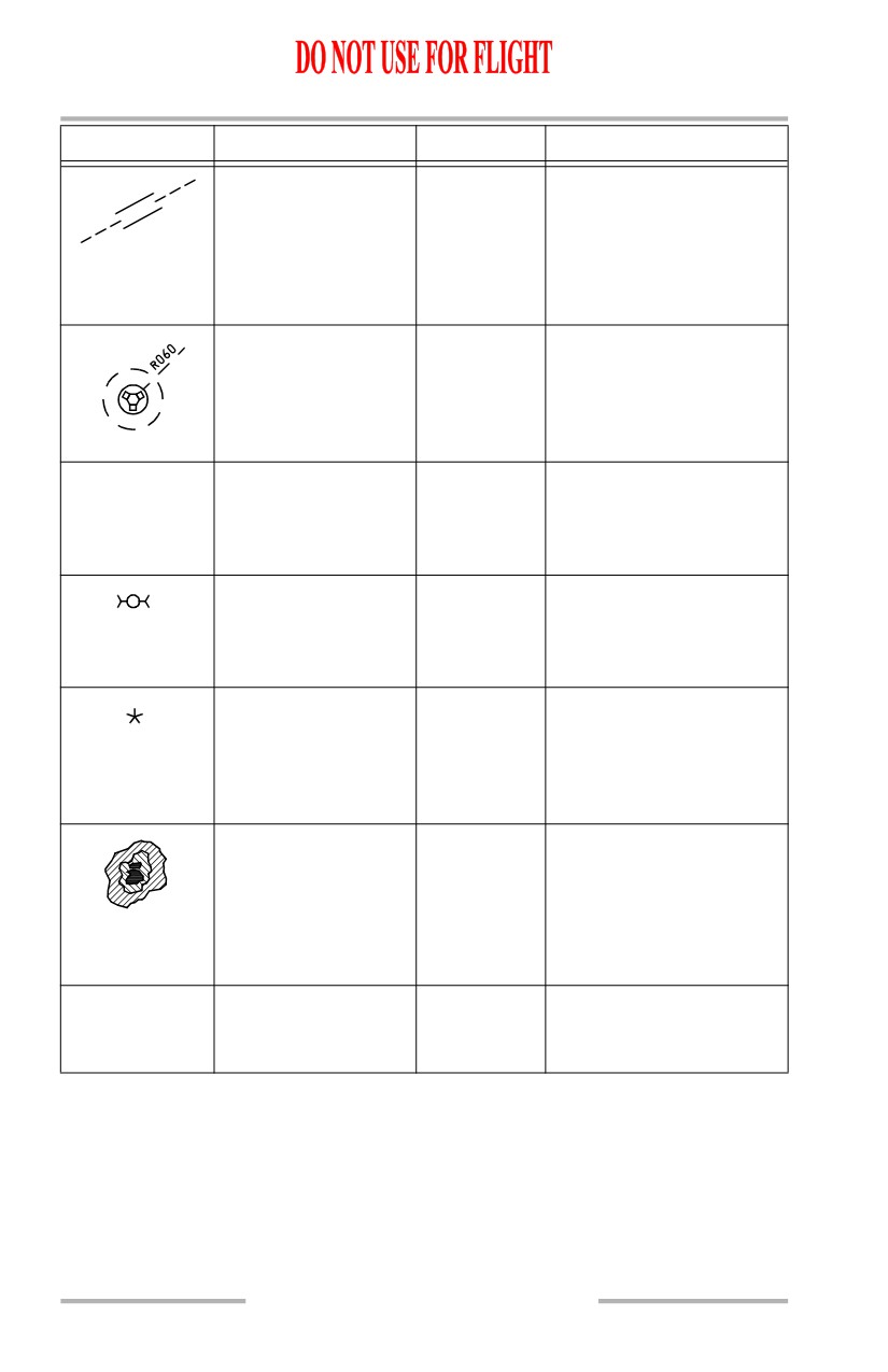
SYMBOL
NAME
ND MODE
REMARKS
Predictive windshear
MAP,
Displays windshear
symbol (R, B, A)
MAP CTR,
location and approximate
APP,
geometric size (width and
VOR
depth).
Amber radials extend from
predictive windshear
symbol to help identify
location of windshear
event.
Windshear
All
Predictive windshear
WINDSHEAR
annunciation (R, A)
caution active (A).
Predictive windshear
warning active (R).
Predictive windshear
All
Predictive windshear
PWS FAIL
status annunciation
alerting and display have
(A)
failed.
10.41.16
Flight Instruments, Displays -
PFD/ND Navigation Displays
Boeing 737 Operations Manual
TCAS
[Option - 3NM TCAS range ring]
SYMBOL
NAME
ND MODE
REMARKS
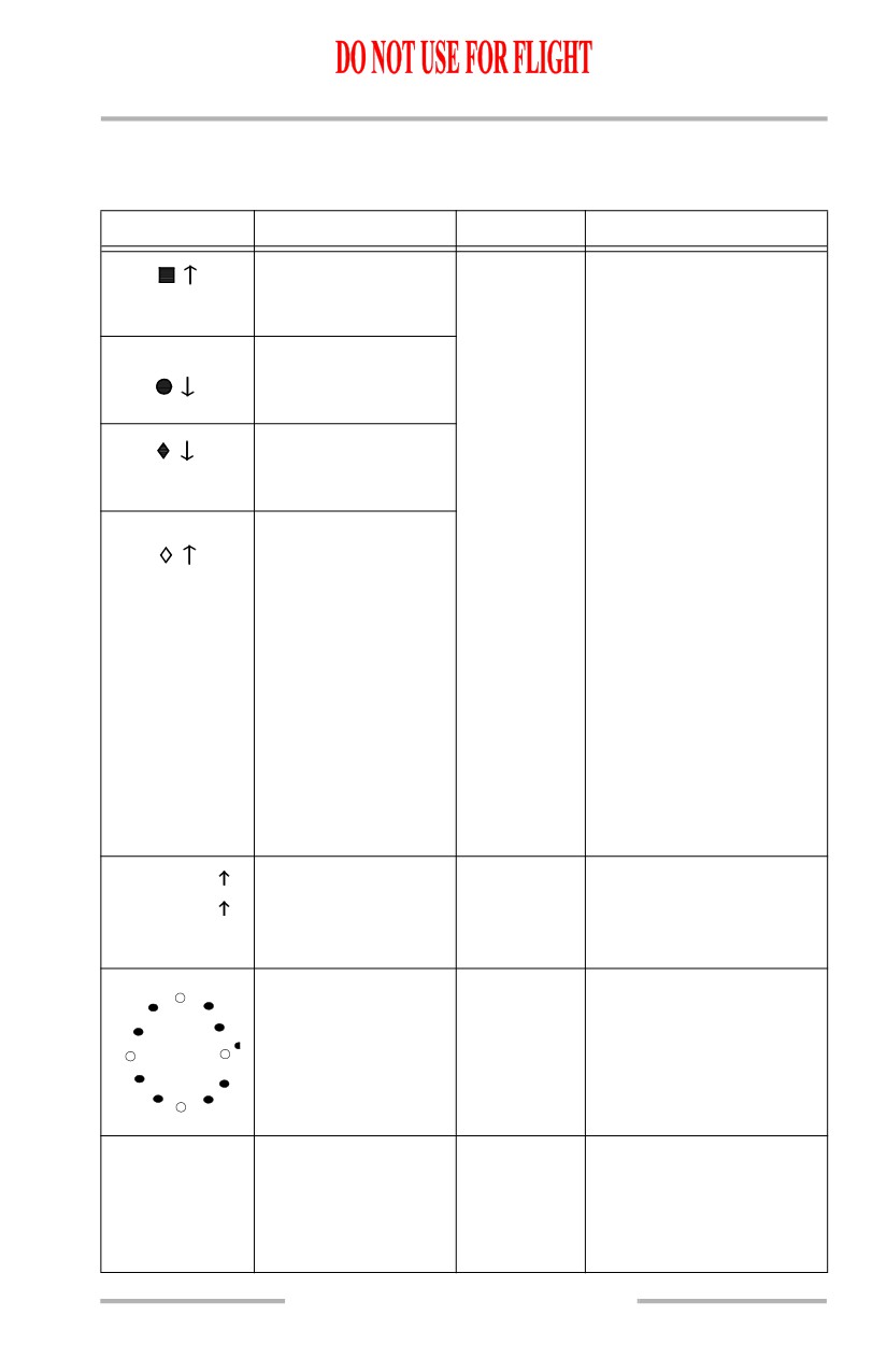
TCAS resolution
MAP,
These symbols are
advisory (RA),
MAP CTR,
displayed only when the
-03
relative altitude (R)
APP,
EFIS control panel traffic
VOR
(TFC) switch is selected
TCAS traffic advisory
+02
on. Refer to Chapter 15,
(TA), relative altitude
Warning Systems.
(A)
The arrow indicates traffic
TCAS proximate
climbing or descending at a
traffic, relative
-05
rate greater than or equal to
altitude (W)
500 fpm. At rates less than
500 fpm, the arrow is not
TCAS other traffic,
+09
displayed.
relative altitude (W)
The number and associated
signs indicate altitude of
traffic in hundreds of feet
relative to the airplane.
The number is below the
traffic symbol when the
traffic is below, and above
the traffic symbol when the
traffic is above the airplane.
Absence of the number
implies altitude unknown.
RA 5.3 +03
TCAS no bearing
MAP,
Message provides traffic
message (RA-R,
MAP CTR,
type, range in NM, altitude
TA 8.9 -12
TA-A)
APP,
and vertical direction. TFC
VOR
must be selected on.
Range Ring (W)
MAP,
Displayed when TFC
MAP CTR,
selected on EFIS Control
APP,
Panel. Shows 3 NM range
VOR
ring oriented to aircraft
heading. Displayed at
ranges of 80 NM or less.
TCAS traffic alert
All
Displayed whenever a
TRAFFIC
message (RA-R,
TCAS RA or TA is active.
TA-A)
EFIS control panel TFC
switch does not have to be
selected on.
10.41.17