Boeing 737 - 600/700/800/900. Operations Manual (1997 year) - page 54
Flight Instruments, Displays -
PFD/ND Navigation Displays
Boeing 737 Operations Manual
SYMBOL
NAME
ND MODE
REMARKS
TCAS off scale
MAP,
Displayed whenever RA or
OFFSCALE
message (RA-R,
MAP CTR,
TA traffic is outside the
TA-A)
APP,
traffic area covered by the
VOR
ND range. Displayed only
if the EFIS control panel
TFC switch is selected on.
TCAS mode (C)
MAP,
Indicates the ND TCAS
TFC
MAP CTR,
display is active; the EFIS
APP,
control panel TFC switch is
VOR
selected on.
TCAS mode (C)
All
Indicates TCAS computer
TA ONLY
is not computing RAs.
Displayed whether the
EFIS control panel TFC
switch is selected on or off.
TCAS mode (C)
All
Indicates TCAS is
TCAS TEST
operating in the test mode.
Displayed whether EFIS
control panel TFC switch is
selected on or off.
TCAS mode (A)
All
Displayed when the
TCAS
TCAS/ATC mode switch is
OFF
not in TA ONLY or TA/RA,
whether EFIS control panel
TFC switch is selected on
or off. Not displayed if
TCAS is failed.
TCAS mode (A)
All
Indicates TCAS failure,
TCAS
whether EFIS control panel
FAIL
TFC switch is selected on
or off. Once displayed, can
be cycled on/off with the
TFC switch.
10.41.18
Boeing 737 Operations Manual
Flight Instruments, Displays
Chapter 10
Head-Up Display System, Symbology
Section 42
Introduction
HUD symbology consists of green symbols projected on the combiner from the
OHU. The PRI mode display symbols are similar to those on the CDS, and can be
used for all phases of flight. The approach mode displays (AIII, IMC, VMC) are
optimized to enhance aircraft control and situational awareness during final
approach, flare, and touchdown.
In addition to flight symbology, TCAS resolution advisories and HUD system
failure flags and data source annunciations are displayed when active.
Head-Up Guidance Display Symbology
[Option - Model 2350]
The following symbols can be displayed on the combiner, depending on HUD and
EFIS control panel switch selections.
SYMBOL
NAME
MODE
REMARKS
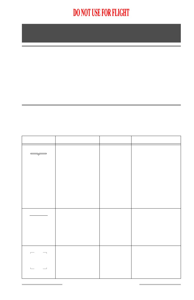
Airplane reference
All
Top center point of the
symbol represents
airplane projected
centerline. The symbol is
positioned at a fixed
position 7 ° above the
display’s vertical center.
Symbol is fixed at
display center when the
unusual attitude display
is active.
Horizon Line
All
Indicates the horizon
relative to the airplane
reference symbol.
Position based on current
airplane pitch and roll
attitude.
Pitch Scale
PRI in flight,
Displays airplane pitch in
5
5
AIII approach,
five degree increments
IMC, VMC
between -20 ° and +25 °.
-5
-5
October 15, 2001
10.42.1
Flight Instruments, Displays -
Head-Up Display System,
Symbology
Boeing 737 Operations Manual
SYMBOL
NAME
MODE
REMARKS
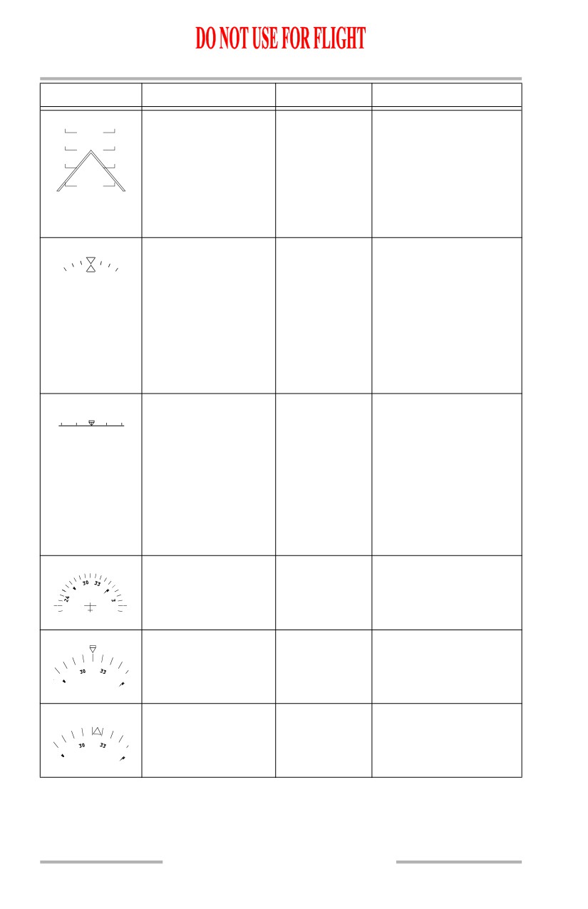
Compressed pitch
PRI in flight,
Displays airplane pitch in
-10
-10
scale
AIII approach,
ten degree increments
-20
-20
IMC, VMC
between +/-30 ° and
-30
-30
+/-90 °.
-40
-40
A chevron appears on the
pitch scale at -20 ° and
+30 °.
Bank Scale and
All
Displays the
Pointer
corresponding roll
attitude in ten degree
increments between 0 °
and +/-30 °. Tic marks at
+/-45 ° and +/-60 ° are
added when the airplane
exceeds +/-35 ° and
+/-50 ° respectively.
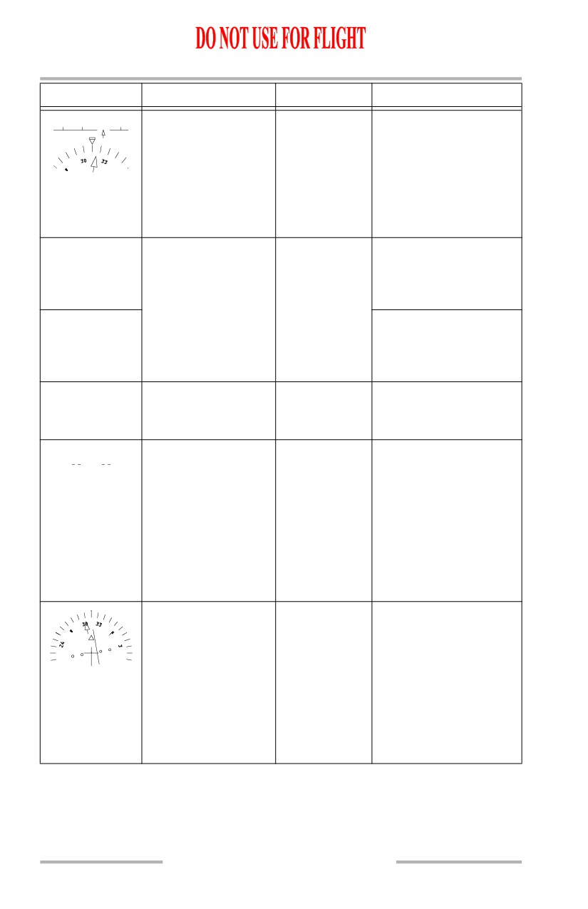
Horizon heading scale
All
Magnetic heading is
29
30
31
displayed in five degree
increments (and labeled
every 10 °) on the
horizon line.
A downward pointing
triangle indicates current
airplane magnetic
heading.
HSI heading scale
PRI in flight
Displays airplane
magnetic heading in a
210 ° compass rose
format.
Heading pointer
PRI in flight
Indicates current heading.
Drift angle pointer
PRI in flight
Indicates current drift
angle or track.
10.42.2
October 15, 2001
Flight Instruments, Displays -
Head-Up Display System,
Symbology
Boeing 737 Operations Manual
SYMBOL
NAME
MODE
REMARKS
31
32
Selected heading bug
All
Displays selected
heading on the horizon
line and on the HSI
(when in view).
Not displayed if the
selected heading is
outside of the currently
displayed heading scale.
Digital selected
All
Displayed full time in
heading
PRI mode and for five
HDG 315
seconds after selection in
the IMC, VMC or AIII
modes.
Digital heading
All
Displays current
H 310
magnetic heading
directly below the roll
scale pointer.
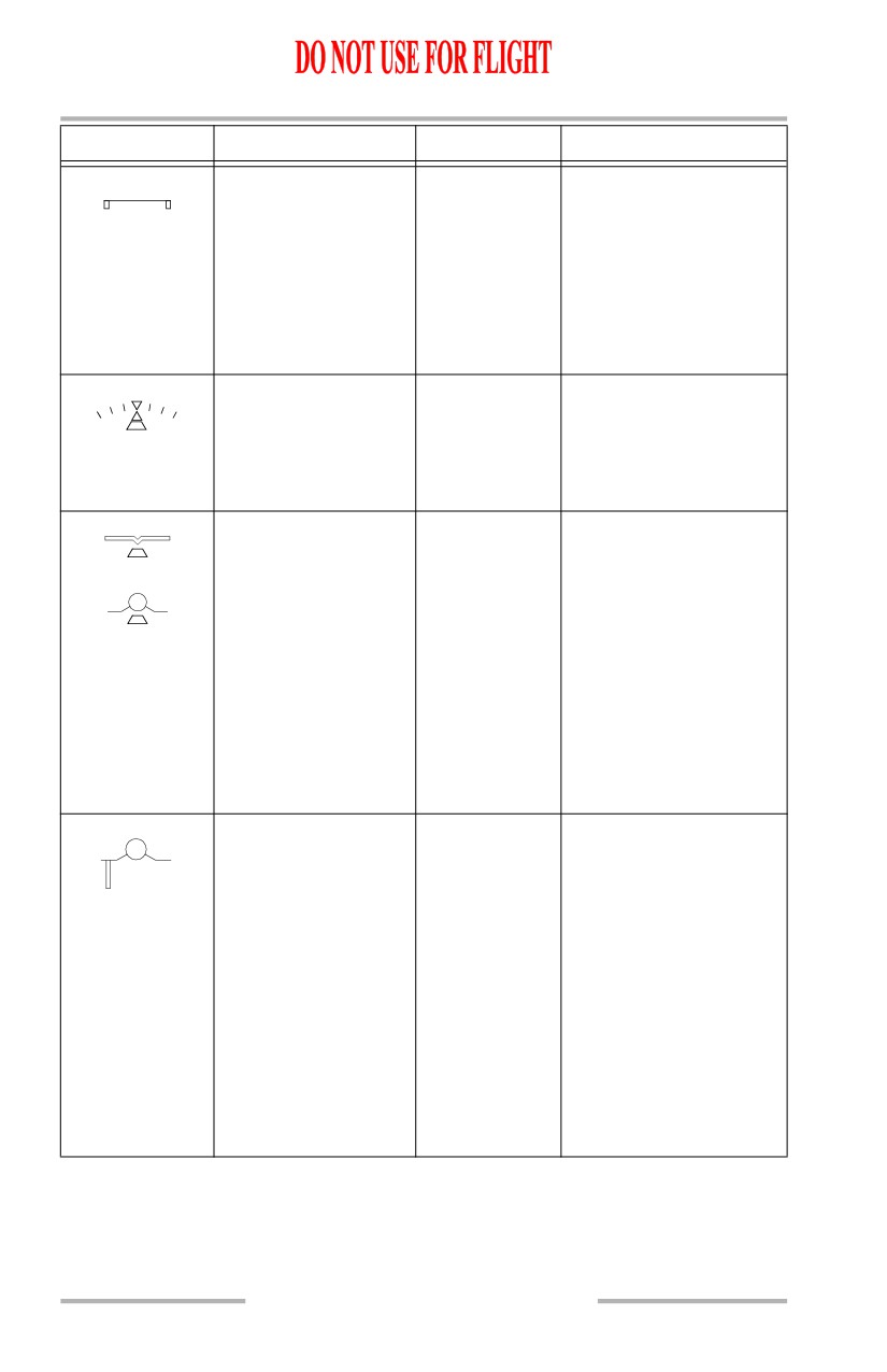
Ground roll reference
PRI ground
Provides a reference for
ground roll guidance
during low visibility
takeoff operations.
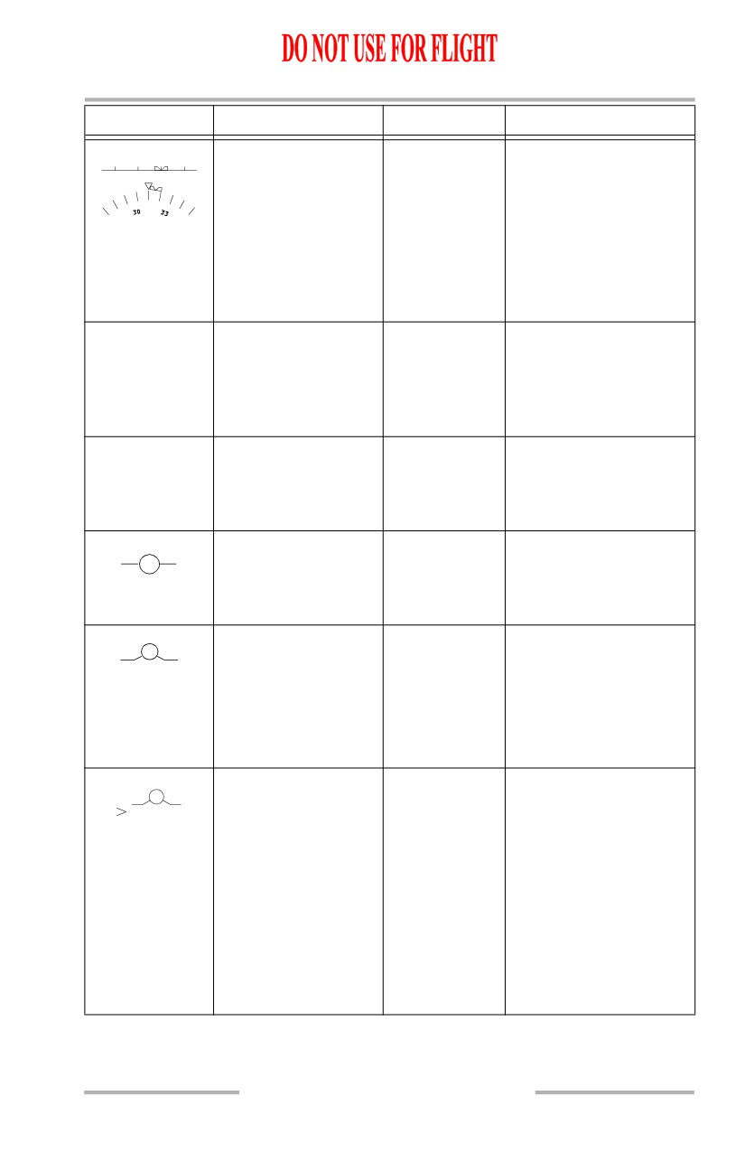
Flight path vector
PRI in flight,
Displays the actual flight
AIII approach,
path vector of the aircraft.
IMC, VMC
Has display priority over
all other symbols except
the guidance cue and the
FLARE command.
Flight path
All
Positioned left of the
acceleration
flight path vector;
indicates sum of all
forces affecting the
airplane including thrust,
drag, and wind.
Positioned above flight
path vector; airplane is
accelerating. Positioned
below flight path vector;
airplane is decelerating.
10.42.3
Flight Instruments, Displays -
Head-Up Display System,
Symbology
Boeing 737 Operations Manual
SYMBOL
NAME
MODE
REMARKS
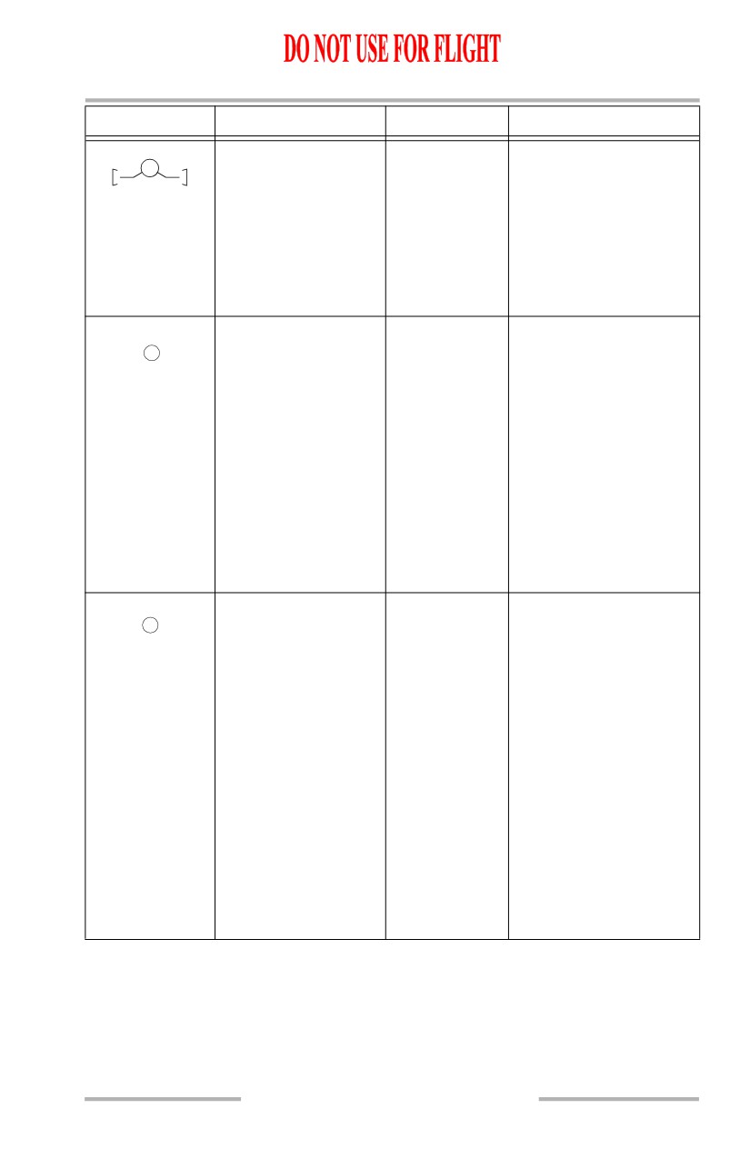
Pitch limit indication
PRI in flight,
Displayed whenever the
(also called angle of
AIII approach,
airplane’s angle of attack
attack limit)
IMC, VMC
is within 5 ° of stick
shaker, any time stick
shaker is active, or
whenever WINDSHEAR
guidance cue is
displayed.
Slip/skid indicator
All
The bottom portion of the
bank scale pointer moves
laterally with respect to
the top triangle portion of
the pointer.
Additional slip/skid
PRI in flight,
Positioned below the
indicators
AIII approach,
airplane reference and
IMC, VMC
flight path symbols.
Displayed during takeoff
until 1500 feel AGL.
Displayed (bold) on
approach, if TO/GA is
engaged below 1000 feet
AGL, and remain until
1500 feet AGL, or when
TO/GA mode is exited.
Speed error tape
PRI in flight,
Displays the difference
AIII approach,
between indicated
IMC, VMC
airspeed and the
reference speed selected
on the mode control
panel.
Tape length equal to the
diameter of the flight
path circle represents
approximately 5 knots of
error. Maximum tape
length is limited to 15
knots of error.
10.42.4
Flight Instruments, Displays -
Head-Up Display System,
Symbology
Boeing 737 Operations Manual
SYMBOL
NAME
MODE
REMARKS
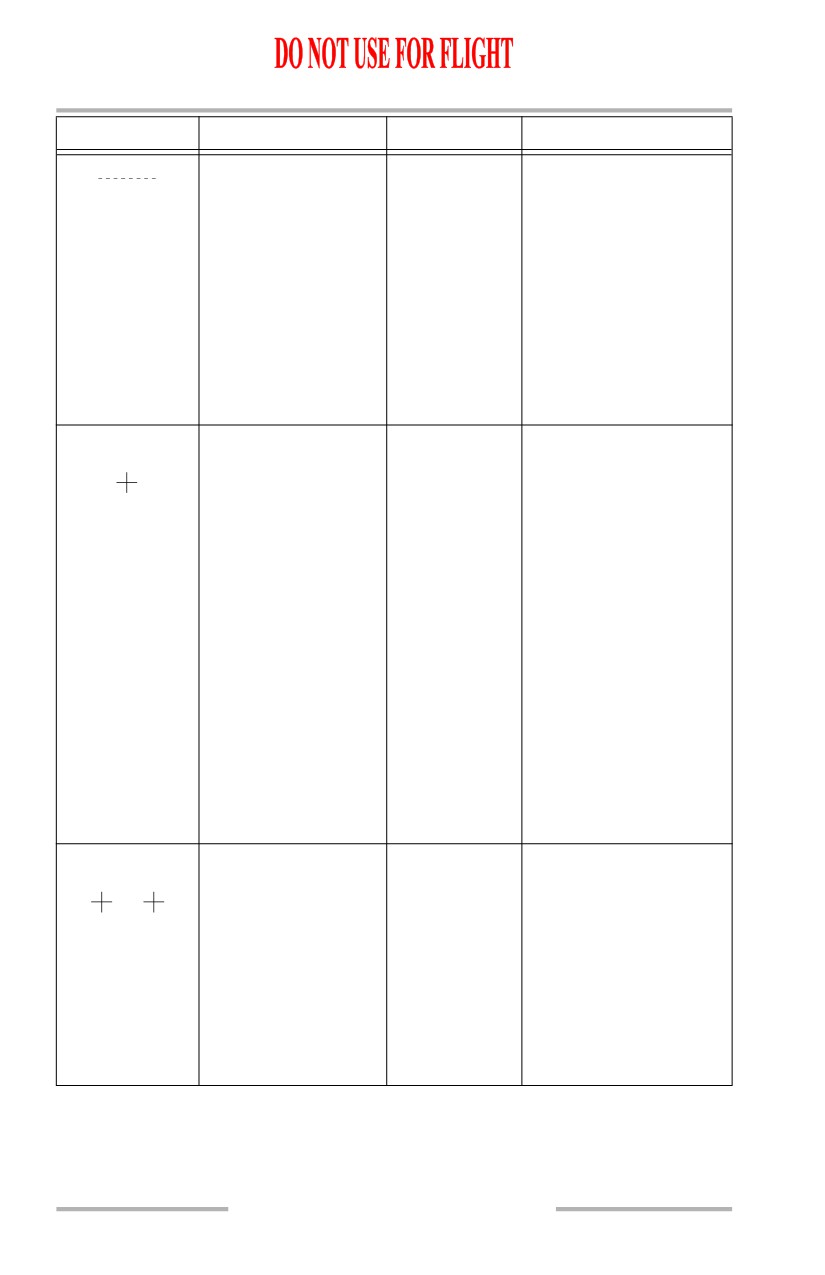
Bank warning
PRI in flight,
Displayed if radio
AIII approach,
altitude is less than 100
IMC, VMC
feet and airplane roll
angle exceeds 5 °.
Symbol remains until roll
angle is less than 3 ° or
radio altitude greater than
100 feet.
Flight director
PRI in flight,
Functions similar to the
guidance cue
IMC
flight director, but is
designed for control of
flight path.
Automatically displayed
when pitch is less than 2°
or radio altimeter
indicates 50 feet.
The objective is to
capture the guidance cue
inside the flight path
vector circle.
HUD guidance cue
PRI ground,
Similar to flight director
AIII approach
guidance cue, but driven
by HUD computer.
During low visibility
takeoff, the cue provides
localizer tracking.
During AIII approach,
the cue provides
approach and flare
commands.
The objective is to
capture the guidance cue
inside the flight path
vector or ground roll
reference circle.
10.42.5
Flight Instruments, Displays -
Head-Up Display System,
Symbology
Boeing 737 Operations Manual
SYMBOL
NAME
MODE
REMARKS
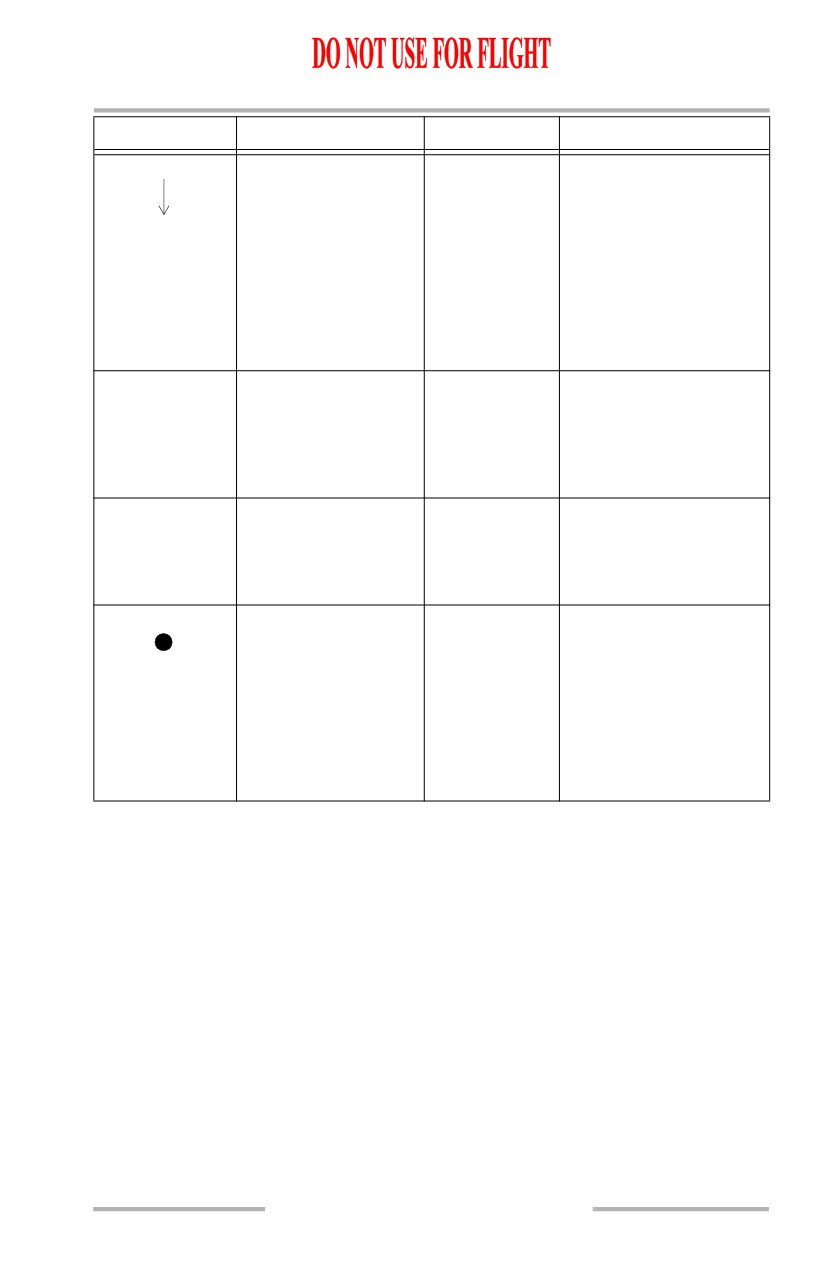
TO/GA pitch target
PRI in flight,
Displayed when greater
line
PRI ground
than 65 knots, AFDS
TO/GA mode active and
a valid pitch command
input of greater than 10 °
is received. Symbol
remains until TO/GA
mode is exited.
The objective is to place
the airplane reference
symbol on the target line.
AIII flare command
AIII approach
Initially displayed 2-3 °
directly below the
guidance cue at 105 feet
above runway elevation.
The symbol flashes for
one second and rises
toward the guidance cue
at a rate proportional to
the expected flare pitch
rate.
At an altitude between 45
and 55 feet, the flare
command and guidance
cue meet and continue
rising to command the
flare maneuver until
touchdown.
Flare cues
PRI in flight,
Displayed on each side of
IMC, VMC
the flight path symbol,
indicating the flare
maneuver must be
accomplished. The cues
flash continuously as the
airplane descends
through 55 feet radio
altitude, until 10 feet
radio altitude is reached.
10.42.6
Flight Instruments, Displays -
Head-Up Display System,
Symbology
Boeing 737 Operations Manual
SYMBOL
NAME
MODE
REMARKS
Wind direction/speed
PRI in flight,
Indicates wind speed and
and wind arrow
AIII approach,
direction, with respect to
IMC,VMC
airplane magnetic
28
heading. Displayed if
wind magnitude is
greater than 6 knots and
blanked if wind
magnitude becomes less
than 4 knots.
Windshear warning
PRI in flight,
Displayed above the
WINDSHEAR
AIII approach,
airplane reference
IMC,VMC
symbol during a GPWS
or PWS windshear
warning.
Ground proximity
PRI in flight,
Displayed whenever the
PULL UP
warning
AIII approach,
GPWS is activated.
IMC,VMC
Windshear guidance
PRI in flight
During a windshear
cue
warning, and in TO/GA
mode, the PRI mode is
automatically selected
and the guidance cue
becomes a solid circle to
provide guidance to exit
windshear conditions.
10.42.7
Flight Instruments, Displays -
Head-Up Display System,
Symbology
Boeing 737 Operations Manual
SYMBOL
NAME
MODE
REMARKS
Radio altitude
PRI in flight,
Displayed below the
AIII approach,
flight path symbol, or
250
IMC,VMC
relative to the airplane
reference symbol if the
flight path symbol is not
displayed.
The value is removed
from the display at 1500
feet when ascending and
again displayed at 1400
feet when descending.
This value is displayed in
ten foot increments
between 50 and 1500
feet, five foot increments
between 10 and 50 feet
and one foot increments
between -20 and 10 feet.
Decision height
PRI in flight,
Displayed left of radio
AIII approach,
altitude when selected
DH
IMC
decision height is
reached.
When decision height is
reached, the message
flashes for 3 seconds and
then remains steady.
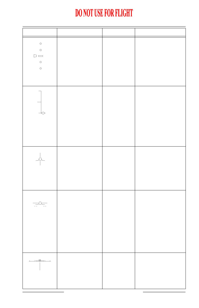
Marker beacon
PRI in flight,
Displayed below the
OM
or
AIII approach,
airplane reference
MM
IMC
symbol for marker
or
IM
beacon passage.
Digital airspeed
AIII approach,
Displays airspeed next to
AIII rollout,
the flight path symbol if
210
IMC, VMC
it is displayed, and next
to the airplane reference
symbol if flight path is
not displayed.
Digital selected
All
Displays speed selected
AS
airspeed
on the MCP.
210
10.42.8
Flight Instruments, Displays -
Head-Up Display System,
Symbology
Boeing 737 Operations Manual
SYMBOL
NAME
MODE
REMARKS
Digital ground speed
All
Displays digital ground
GS
speed.
120
Digital mach
PRI in flight
Displays mach speed
below airspeed scale
.540
when mach speed is
above .400. Removed
when below .380.
Selected mach
All
Displays selected mach
speed above airspeed
.39
scale (PFD/ND format
only).
Digital barometric
AIII approach,
Displays barometric
altitude
AIII rollout,
altitude relative to the
450 B
IMC, VMC
flight path symbol if it is
displayed, and relative to
the airplane reference
symbol if flight path is
not displayed.
Digital vertical speed
PRI in flight,
In PRI mode, displayed
AIII approach,
in the lower right corner
600 VS
IMC, VMC
of the display. In all other
modes, displayed to the
right of the flight path
symbol.
Value displayed in 50
feet/minute increments.
DME distance
PRI in flight,
Indicates DME distance
AIII approach,
to the reference navaid.
DME28.4
IMC, VMC
Distance to go
PRI in flight,
Distance to next
IMC
waypoint.
58.4NM
Selected course
All
Displayed full time in
(digital)
PRI mode and for five
CRS 316
seconds after selection in
the IMC, VMC or AIII
modes.
10.42.9
Flight Instruments, Displays -
Head-Up Display System,
Symbology
Boeing 737 Operations Manual
SYMBOL
NAME
MODE
REMARKS
31
32
Selected course
All
Displays MCP selected
pointer
course below the horizon
line and on the HSI (PRI
mode only).
The horizon line pointer
is surrounded by a 3 ° gap
in the horizon line.
System source
PRI in flight,
Indicates the selected
VOR 1,2
annunciation
PRI ground,
receiver as the display
ILS 1,2
AIII approach,
source.
AIII rollout
IMC
Indicates source cannot
VOR/ILS
be determined.
FMC source
All
Indicates the selected
FMC L, R
annunciation
FMC as the system
source.
Glideslope reference
AIII approach,
Displays the glideslope
-3.00
-3.00
line
IMC, VMC
value entered on the
HUD control panel.
Positioning the flight
path symbol over the
glideslope reference line
results in a descent angle
equal to the value
entered.
ILS localizer or VOR
PRI in flight
Displays LOC or VOR
deviation indication
course deviation on the
and scale
HSI.
With excessive localizer
deviation during an ILS
approach, the symbol will
flash until the excessive
deviation is no longer
present.
10.42.10
Flight Instruments, Displays -
Head-Up Display System,
Symbology
Boeing 737 Operations Manual
SYMBOL
NAME
MODE
REMARKS
Glideslope pointer and
PRI in flight
Displays glideslope
deviation scale
position and deviation
during ILS approach.
With excessive
glideslope deviation, the
pointer will flash until the
excessive deviation is no
longer present.
Vertical deviation
PRI in flight,
Full scale represents 400
pointer and scale
IMC
feet of vertical deviation.
When the deviation is off
scale, the pointer is
parked at the top or
460
bottom of the tape, and
the digital value is
displayed at the
appropriate end of the
scale.
Lateral deviation line
AIII approach,
Displayed as vertical
IMC
lines referenced to the
selected course.
In IMC mode, the line
will flash during
excessive localizer
deviation.
Glideslope deviation
AIII approach,
Displayed as horizontal
line
IMC
lines referenced to the
-3.00
-3.00
glideslope reference line.
In IMC mode, the line
will flash during
excessive glideslope
deviation.
The line is removed
below 70 feet radio
altitude.
29
30
31
Ground localizer line
PRI ground,
Displays localizer
AIII rollout,
deviation as a vertical
IMC
line below the airplane
reference symbol and is
referenced to the selected
course.
October 15, 2001
10.42.11
Flight Instruments, Displays -
Head-Up Display System,
Symbology
Boeing 737 Operations Manual
SYMBOL
NAME
MODE
REMARKS
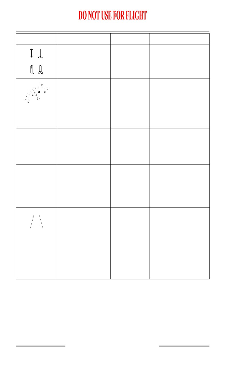
VOR1/ADF 1 pointer
PRI in flight
Indicates bearing to
head and tail
(head) or from (tail) the
tuned station.
VOR2/ADF 2 pointer
head and tail
To/from pointer
PRI in flight,
A triangle pointing in the
PRI ground
same direction as the
selected course indicates
a “to” condition. Pointing
away from the selected
course indicates a “from”
condition.
TO/FROM
AIII approach,
Displayed below the
VOR1
annunciation
IMC
VOR system source
FROM
annunciation. Indicates
movement to or from a
VOR station.
Runway elevation
AIII approach
Indicates entered runway
elevation for 5 seconds
ELV 426
after AIII mode is
selected or if elevation
value is changed during
AIII mode operation.
Runway edge lines
AIII approach
Displayed between 300
and 60 feet radio altitude.
The lines are scaled to a
width of 200 feet and a
length of 8000 feet.
Tic marks are displayed
at the touchdown
aimpoint representing
1050 feet from the
runway threshold.
10.42.12
Flight Instruments, Displays -
Head-Up Display System,
Symbology
Boeing 737 Operations Manual
SYMBOL
NAME
MODE
REMARKS
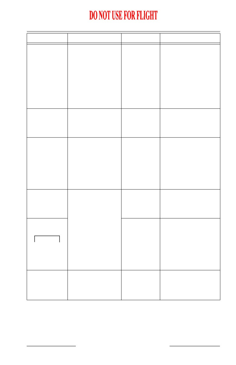
IDLE message
AIII approach
Displayed below the
radio altitude when flare
IDLE
guidance commands a
thrust reduction to idle
for touchdown.
Message is displayed
between 25 and 5 feet
radio altitude, continuing
until touchdown.
ALIGN HUD message
IMC, VMC
Indicates the combiner is
not properly aligned with
ALIGN HUD
the OHU.
HUD system mode
AIII approach,
Indicates current HUD
IMC
or
AIII rollout,
system mode.
VMC
IMC, VMC
or
The PRI mode is not
AIII
indicated as it is uniquely
identifiable by the
airspeed and altitude
tapes.
AIII approach status
PRI in flight
A flashing “AIII”
indicates availability of
A
III
AIII approach mode.
AIII approach
Indicates AIII mode
AIII
selection once all AIII
or
approach requirements
NO AIII
have been satisfied.
If AIII capability is lost,
the “NO AIII” status
message is displayed.
Approach warning
AIII approach
Displayed below 500 feet
if approach monitoring
APCH WARN
tolerances are exceeded
or AIII capability is lost.
10.42.13
Flight Instruments, Displays -
Head-Up Display System,
Symbology
Boeing 737 Operations Manual
TCAS Resolution Advisory
SYMBOL
NAME
MODE
REMARKS
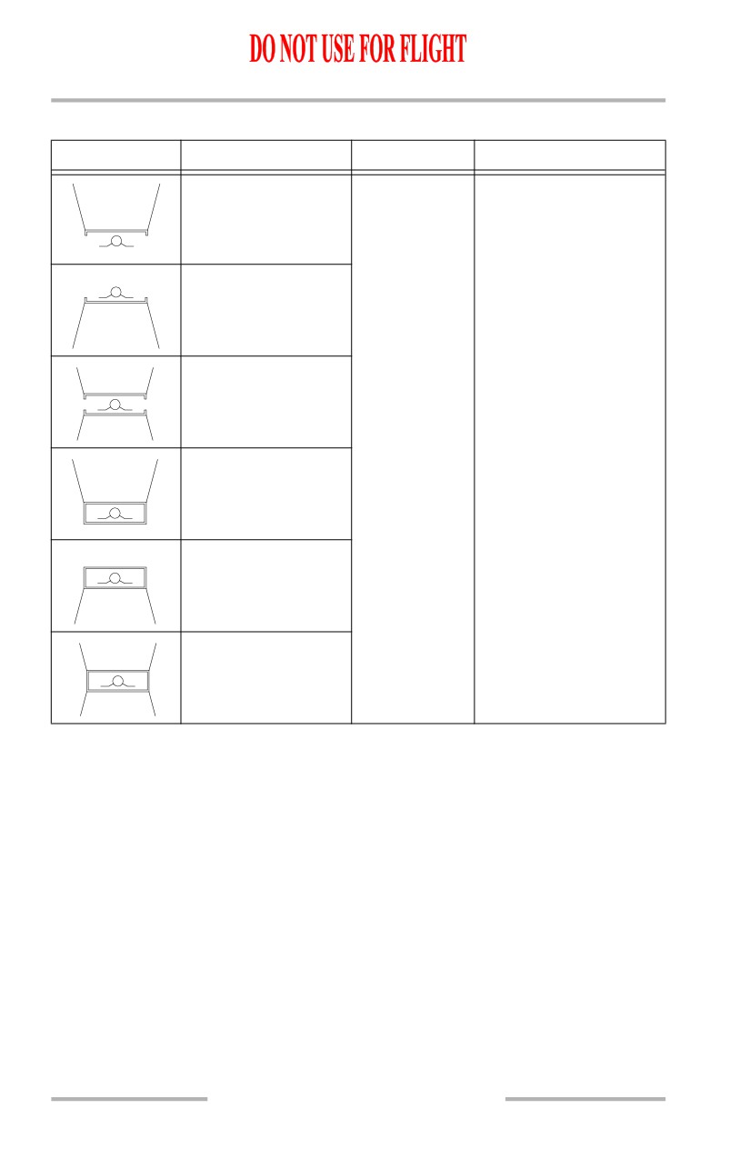
Down preventive
PRI in flight,
Area(s) inside the lines
AIII approach,
indicate the pitch
IMC, VMC
region(s) to avoid in
order to resolve the traffic
conflict. The flight path
Up preventive
symbol should be
positioned outside the
pitch command area(s) to
ensure traffic avoidance.
Up and down
A double-lined box
preventive
indicates a corrective
action is required, and
represents TCAS
maneuver guidance to
Descend corrective
maintain or increase
separation from the
traffic.
Climb corrective
Combined corrective
10.42.14
Flight Instruments, Displays -
Head-Up Display System,
Symbology
Boeing 737 Operations Manual
Failure Flags and Data Source Annunciations
SYMBOL
NAME
MODE
REMARKS
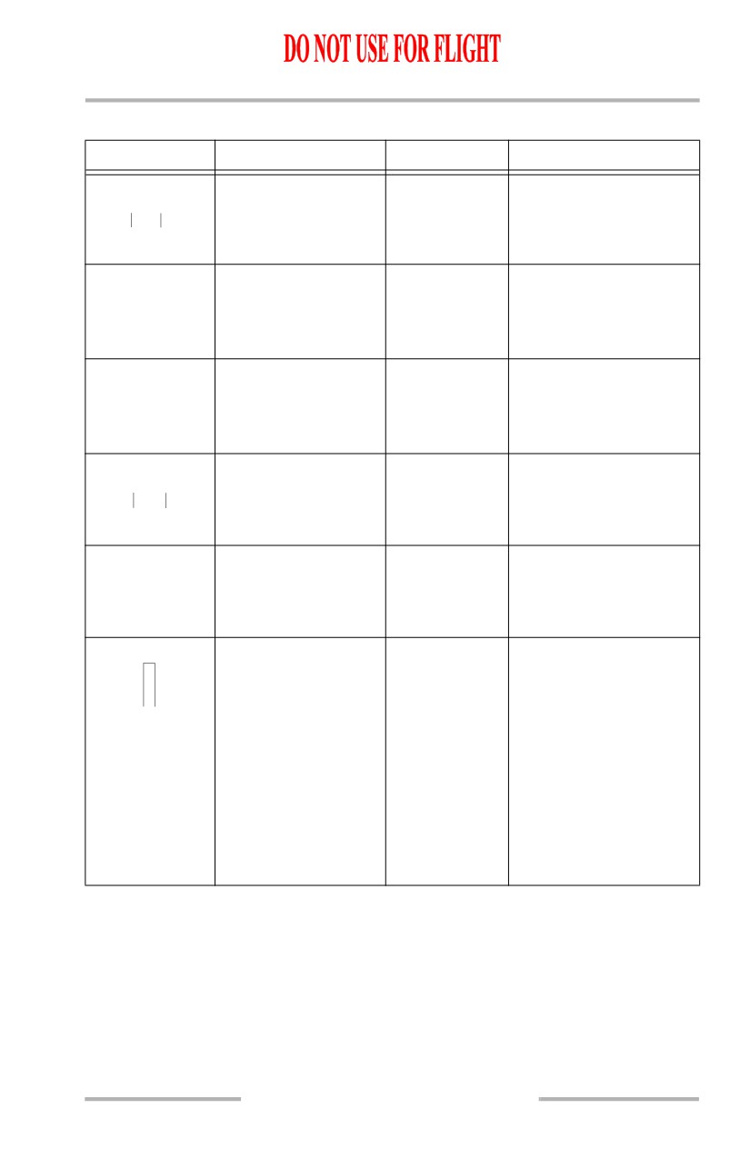
IRS attitude flag
All
IRS pitch or roll attitude
has failed.
ATT
Pitch miscompare flag
All
Indicates a pitch
miscompare of greater
PITCH
than 5 ° for more than 1.5
seconds.
Roll miscompare flag
All
Indicates a roll
miscompare of greater
ROLL
than 5 ° for more than 1.5
seconds.
Heading flag
All
Heading data has failed.
HDG
No heading
All
IRU heading has no
computed data.
H ---
Airspeed flag
All
Airspeed information has
S
failed. In PRI mode, if
P
airspeed has no computed
D
data, airspeed data is
removed and no failure
flag is displayed.
The boxed characters are
positioned vertically in
the PRI mode or
horizontally in the AIII,
IMC or VMC modes.
10.42.15
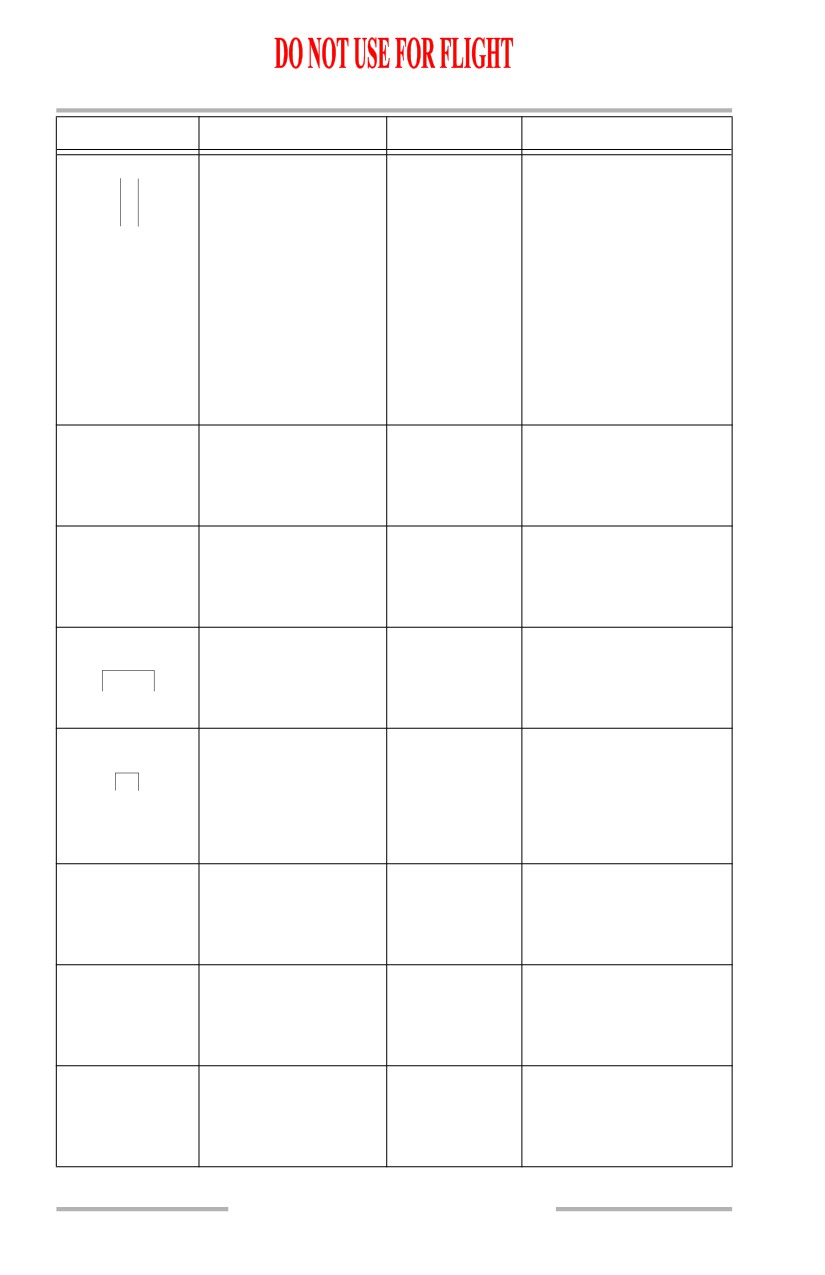
Flight Instruments, Displays -
Head-Up Display System,
Symbology
Boeing 737 Operations Manual
SYMBOL
NAME
MODE
REMARKS
Altitude flag
All
Altitude information has
A
failed. In PRI mode, if
L
T
altitude has no computed
data, altitude data is
removed and no failure
flag is displayed.
The boxed characters are
positioned vertically in
the PRI mode or
horizontally in the AIII,
IMC or VMC modes.
Decision speed flag
PRI ground
V1 decision speed or VR
rotation speed has not
NO
VSPD
been entered or is invalid.
Speed limit flag
PRI in flight,
Maximum operating
PRI ground
speed data has failed.
SPD
LIM
Mach flag
PRI in flight,
MACH airspeed has
PRI ground
failed.
MACH
Vertical speed flag
All
Vertical speed has failed.
In PRI mode, a vertical
VS
speed failure may be
indicated by a dashed line
to the left of the flag.
Vertical speed
PRI in flight,
Vertical speed has no
AIII approach,
computed data.
--- VS
IMC, VMC
Selected altitude flag
PRI in flight,
Selected altitude has
PRI ground
failed.
SEL ALT
Selected airspeed flag
All
Selected speed has failed.
SEL SPD
10.42.16
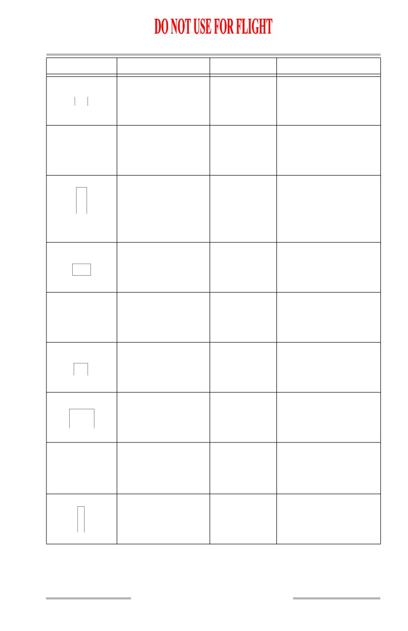
Flight Instruments, Displays -
Head-Up Display System,
Symbology
Boeing 737 Operations Manual
SYMBOL
NAME
MODE
REMARKS
Radio altitude flag
All
Radio altitude has failed.
RA
Localizer miscompare
PRI in flight
Localizer miscompare
flag
PRI ground
has occurred during low
LOC CMP
visibility takeoff.
Vertical deviation flag
PRI in flight,
FMC vertical track data
V
IMC
is invalid.
T
K
Vertical deviation pointer
is removed if there is no
computed data.
DME flag
All
DME has failed.
DME
DME
All
DME has no computed
data.
DME ---
Flight director flag
PRI in flight,
Flight director has failed.
PRI ground,
FD
IMC
TCAS fault
PRI in flight,
TCAS has a fault.
AIII approach,
TCAS
FAIL
IMC, VMC
Right (#2) IRS source
All
All IRS information used
or displayed by the HUD
ATT2
is taken from the right
(#2) IRS.
Glideslope flag
PRI in flight,
Glideslope data has
G
AIII approach,
failed.
/
S
IMC
10.42.17
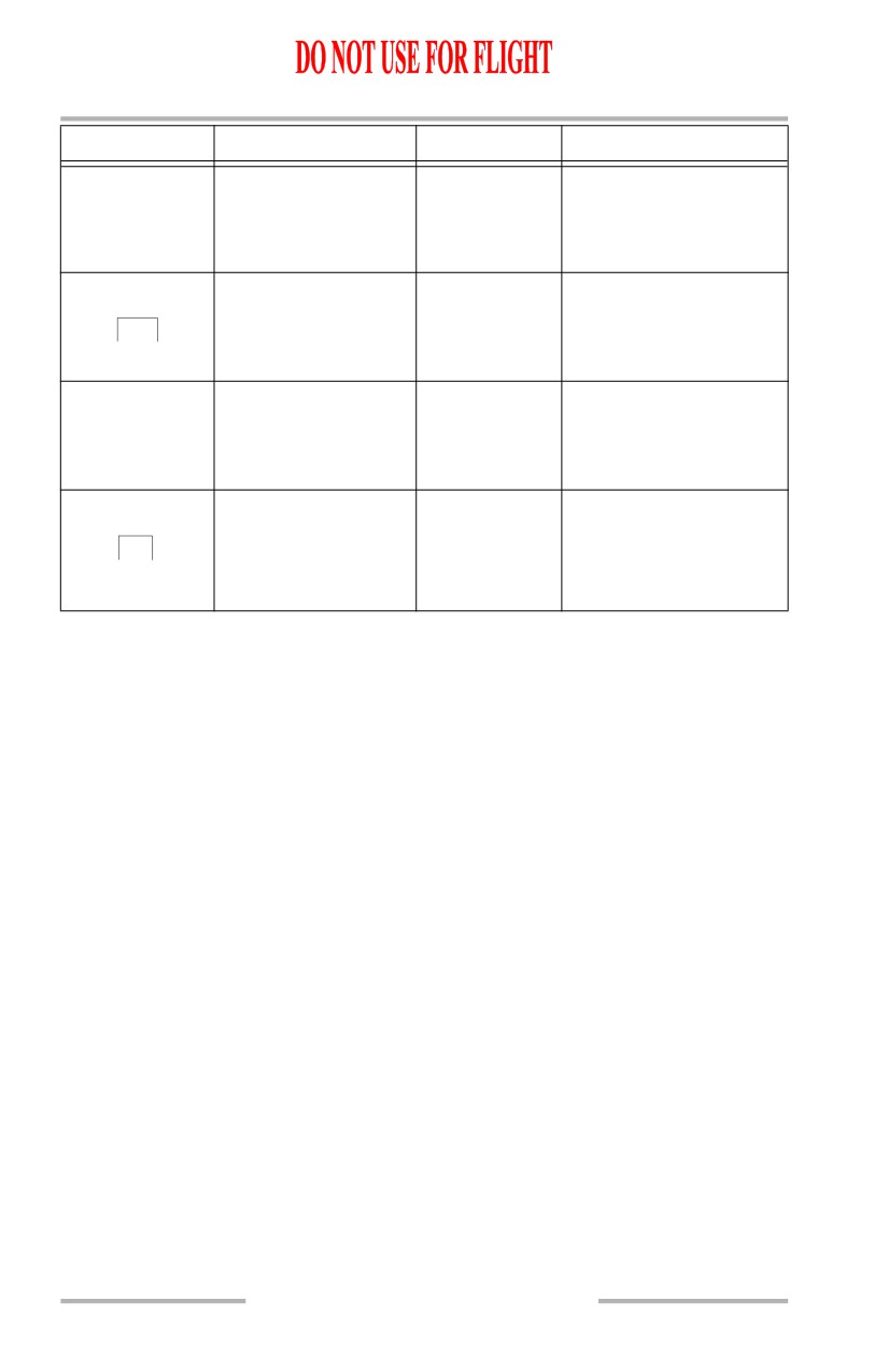
Flight Instruments, Displays -
Head-Up Display System,
Symbology
Boeing 737 Operations Manual
SYMBOL
NAME
MODE
REMARKS
Ground speed
All
Ground speed has no
computed data.
---
Lateral deviation fault
PRI in flight,
Localizer deviation not
PRI ground
valid or VOR bearing not
LOC
valid.
Distance to next
PRI in flight,
Distance to next
waypoint
AIII approach,
waypoint has no
--- NM
IMC, VMC
computed data.
Decision height flag
PRI in flight,
Decision height data has
AIII approach,
failed.
DH
IMC
Displayed below 1500
feet radio altitude.
10.42.18
Boeing 737 Operations Manual
Flight Management, Navigation
Chapter 11
Table of Contents
Section 0
11.0 Flight Management, Navigation-Table of Contents
Controls and Indicators
11.10.1
Flight Management System
11.10.1
Control Display Unit (CDU)
11.10.1
Function and Execute Keys
11.10.4
Alpha/Numeric and Miscellaneous Keys
11.10.7
CDU Page Components
11.10.9
CDU Page Color
11.10.10
FMC Source Select Switch
11.10.12
FMC Alert Light
11.10.12
Global Positioning System (GPS) Light
11.10.13
Inertial System
11.10.14
IRS Display Unit (ISDU)
11.10.14
IRS Mode Selector Unit
11.10.16
IRS Transfer Switch
11.10.18
Radio Navigation Systems
11.10.19
Automatic Direction Finding (ADF) Control
11.10.19
Marker Beacon Annunciations
11.10.21
VHF Navigation Control
11.10.22
VHF NAV Transfer Switch
11.10.24
Transponder Panel
11.10.24
Weather Radar Panel
11.10.27
Navigation Systems Description
11.20.1
Introduction
11.20.1
Flight Management System
11.20.1
Global Positioning System (GPS)
11.20.2
GPS Displays
11.20.2
GPS Data
11.20.3
GPS System Schematic
11.20.4
Inertial System
11.20.5
11.TOC.0.1