Boeing 737 - 600/700/800/900. Operations Manual (1997 year) - page 51
Flight Instruments, Displays -
PFD/ND System Description
Boeing 737 Operations Manual
3
PFD
MFD
ENGINE
MFD
PFD
MFD
MAIN PANEL DUs
LOWER DU
LOWER DU
MAIN PANEL DUs
NORM
NORM
NORM
NORM
OUTBD
ENG
ENG
ND
ND
ENG
ENG
OUTBD
PFD
PRI
PRI
PRI
PRI
PFD
PFD
PFD
INBD
INBD
MFD
MFD
MFD
ENG SYS
1
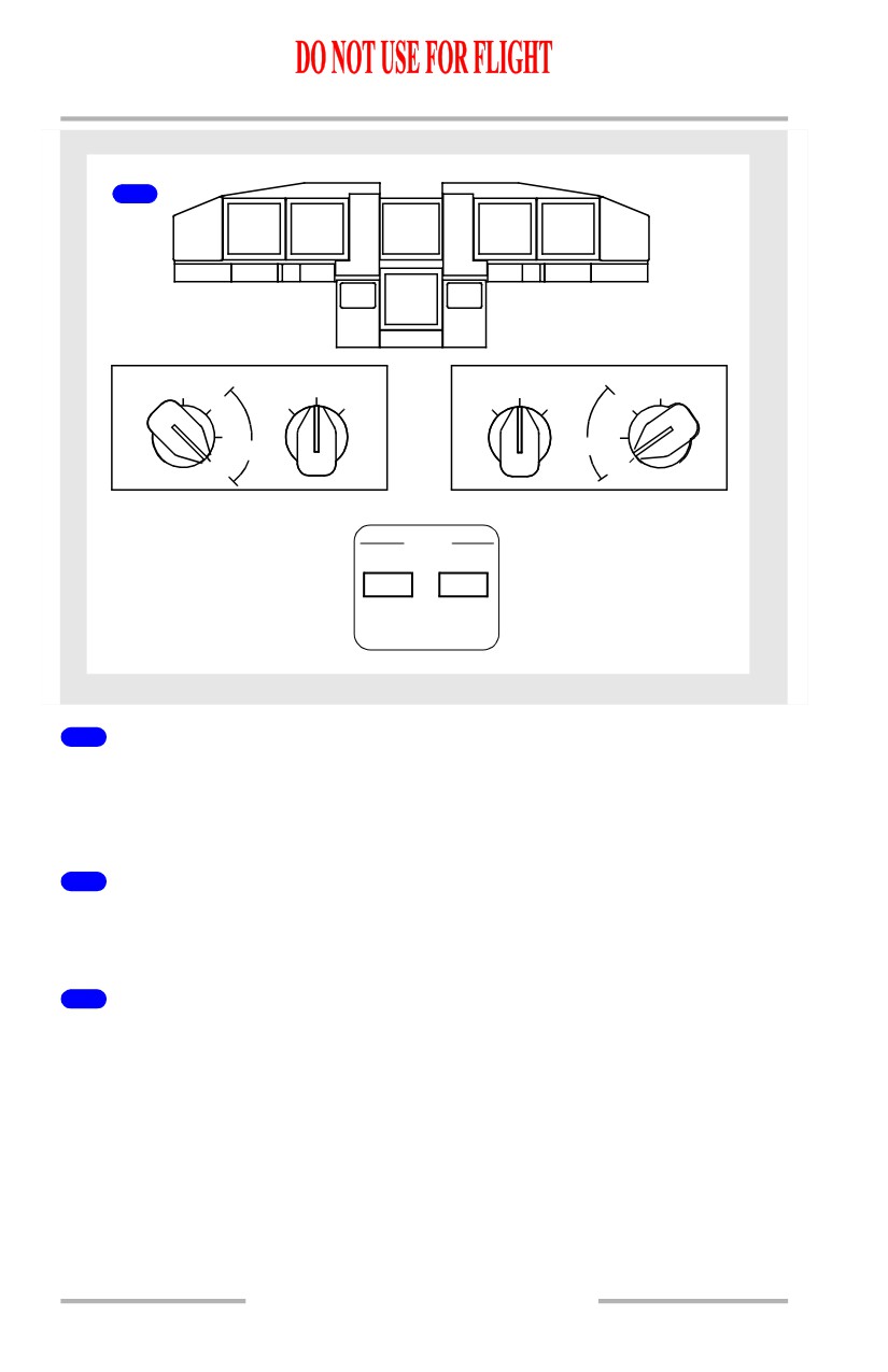
MAIN PANEL DUs Switch to INBD ENG PRI
If the MAIN PANEL DUs switch is turned to INBD ENG PRI, the primary engine
display moves to the inboard DU, the PFD format is displayed on the outboard DU
and the upper DU blanks.
2
MAIN PANEL DUs Switch to INBD PFD
If the MAIN PANEL DUs switch is turned to INBD PFD, the PFD format is
displayed on the inboard DU and the outboard DU blanks.
3
MAIN PANEL DUs Switch to MFD
If the MAIN PANEL DUs switch is turned to INBD MFD, the PFD continues to
be displayed on the outboard display unit and the inboard display is blank. The
system format (SYS) or secondary engine format (ENG) can then be selected to
the inboard display unit and lower display unit with the MFD switches on the
engine display control unit.
10.21.10
Flight Instruments, Displays -
PFD/ND System Description
Boeing 737 Operations Manual
Lower Display Switching
1
PFD
ND
ND
PFD
ENGINE
MAIN PANEL DUs
LOWER DU
LOWER DU
MAIN PANEL DUs
NORM
NORM
NORM
NORM
OUTBD
ENG
ENG
ND
ND
ENG
ENG
OUTBD
PFD
PRI
PRI
PRI
PRI
PFD
PFD
PFD
INBD
INBD
MFD
MFD
2
PFD
ND
ENGINE
ND
PFD
ND
MAIN PANEL DUs
LOWER DU
LOWER DU
MAIN PANEL DUs
NORM
NORM
NORM
NORM
OUTBD
ENG
ENG
ND
ND
ENG
ENG
OUTBD
PFD
PRI
PRI
PRI
PRI
PFD
PFD
PFD
INBD
INBD
MFD
MFD
1
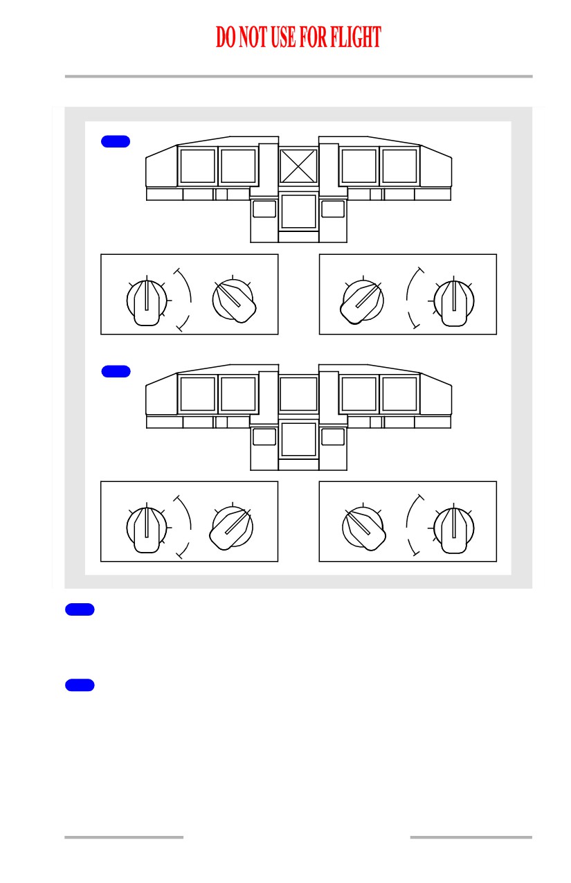
LOWER DU Switch to ENG PRI
If the LOWER DU switch is turned to ENG PRI, the engine display moves to the
lower DU and the upper DU blanks.
2
LOWER DU Switch to ND
If the LOWER DU switch is turned to ND, the engine display is shown on the
upper DU and the navigation display is shown on the lower DU. When the MFD
ENG switch is selected, the compact engine display is shown on the upper DU.
10.21.11
Flight Instruments, Displays -
PFD/ND System Description
Boeing 737 Operations Manual
Display System Information Sources
Air Data Inertial Reference System (ADIRS)
The ADIRS produces flight data such as position, speed, altitude and attitude for
the flight displays, flight management computers, flight controls, engine controls
and all other systems requiring inertial and air data.
The major components of the ADIRS are:
• two air data inertial reference
• six static ports
units (ADIRUs)
• three pitot probes
• four air data modules (ADMs)
• two alpha vanes
• one inertial system display unit
• one total air temperature probe.
(ISDU)
• one dual mode select unit
(MSU)
AUXILIARY
ALPHA
CAPT
F/O
ALT
PITOT PROBE
VANE
STATIC
STATIC
STATIC
PORT
PORT
PORT
F/O PITOT PROBE
TO:STBY
AIRSPD
ADM
ADIRU-R
ADM
TO:
STBY
ADIRU-L
ADM
ALT/
AIRSPD
ADM
CAPT PITOT PROBE
TAT
PROBE
CAPT
F/O
ALT
ALPHA
STATIC
STATIC
STATIC
VANE
PORT
PORT
PORT
PITOT LINES
STATIC LINES
Air Data Inertial Reference Unit (ADIRU)
The ADIRUs provide inertial position and track data to the FMC as well as
attitude, altitude and airspeed data to the displays. The ADIRUs process
information measured by internal gyros and accelerometers, and from air data
module inputs, the alpha vanes and other systems.
The ADIRUs are described in Chapter 11, Flight Management, Navigation.
10.21.12
Flight Instruments, Displays -
PFD/ND System Description
Boeing 737 Operations Manual
Air Data
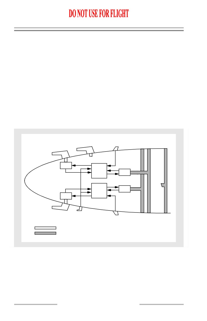
The pitot static system is comprised of three separate pitot probes and six flush
static ports. Two pitot probes and four static ports interface with the air data
modules. The remaining auxiliary pitot probe and alternate static ports provide
pitot and static pressure to the standby instruments. The auxiliary pitot probe is
located on the first officer’s side of the airplane.
The air data modules convert pneumatic pressure to electrical signals and send
these data to the ADIRUs. Each pitot air data module is connected to its on-side
pitot probe; there is no cross connection. The air data module connected to the
Captain’s pitot probe sends information to the left ADIRU, while the air data
module connected to the First Officer’s pitot probe sends information to the right
ADIRU. The remaining air data modules are located at the balance centers of the
Captain’s and First Officer’s static ports. The air data module connected to the
Captain’s static ports sends information to the left ADIRU, while the air data
module connected to the First Officer’s static ports sends information to the right
ADIRU.
Angle-of-Attack
There are two alpha vanes, one located on each side of the forward fuselage. The
vanes measure airplane angle-of-attack relative to the air mass.
[Option - Angle of attack indicator]
The primary source of data for the AOA indicator on the PFD is supplied by the
ADIRU, with the SMYD as the backup source. The source selection is automatic
in the event of primary source failure. Slight differences between the Captain’s
and FO’s indications may be noticed due to sideslip or vane installation errors.
These differences could be as large as 2 degrees alpha.
Total Air Temperature
A total air temperature probe is mounted outside the airplane to sense air mass
temperature. The temperature sensed by the probe is used by the ADIRUs to
compute total air temperature.
Static Air Temperature
Static air temperature, displayed on the CDU PROGRESS page, comes from the
ADIRUs, using total air temperature probe information.
Standby Flight Instruments
The standby flight instruments include:
10.21.13
Flight Instruments, Displays -
PFD/ND System Description
Boeing 737 Operations Manual
• standby magnetic compass
• integrated standby flight
display
• standby radio magnetic
indicator.
Standby Magnetic Compass
A standard liquid-damped magnetic standby compass is provided. A card located
near the compass provides heading correction factors.
Integrated Standby Flight Display (ISFD)
The ISFD displays attitude, airspeed, altitude, ILS, and heading information. It is
connected directly to the auxiliary pitot and alternate static sources. ILS
information is provided by the No. 1 ILS receiver. The display receives its heading
information from the same source as the captain’s primary flight display.
Note: The standby magnetic compass must be used to validate heading
information.
The battery bus powers the ISFD. Selecting the battery switch ON activates the
ISFD. After 10 seconds, an initialization sequence begins that requires 90 seconds
to complete. ATT and INIT 90s messages are displayed during initialization. Upon
completion of the initialization sequence, attitude information is displayed.
Note: Any change in airplane position during the initialization sequence may
result in an inaccurate alignment. Inaccurate alignment is not annunciated
and may result in the display of inaccurate attitude prior to, and during
flight. Re-initialization can only be accomplished through maintenance
action.
Detection of a momentary out-of-limit ISFD condition may cause the attitude
display to blank and the WAIT ATT or ATT:RST message to display. Operation of
the attitude reset switch is required in response to the ATT:RST message. This will
reset the horizon line with the airplane symbol.
Note: Operation of the attitude reset switch will not correct an inaccurate
alignment.
On the ground, operation of the attitude reset switch must be performed with the
airplane stationary. In flight, operation of the attitude reset switch must be
performed with the airplane in wings level, non-accelerated flight. During the
process, the ATT 10s message displays. Failure to maintain straight and level
flight for 10 seconds may result in an ATT:RST message. If the reset attempt is
unsuccessful, the ATT:RST message remains displayed and the ISFD does not
enter normal operation.
10.21.14
Flight Instruments, Displays -
PFD/ND System Description
Boeing 737 Operations Manual
Standby Radio Magnetic Indicator
The standby radio magnetic indicator (RMI) displays magnetic heading and
VOR/ADF bearing to the station. The RMI is powered by the AC standby bus and
remains powered after the loss of all normal AC power as long as battery power
is available.
Clocks
[Option - GPS capable]
Two electronic clocks are installed, with two digital displays on each clock.
Universal time coordinated (UTC) time, UTC date, manual time or manual date
may be set on the upper time display. The lower ET/CHR display is used for either
elapsed time or the chronograph. Separate controls are provided for each display.
Each clock is powered by the hot battery bus when the battery bus is not available.
The clock reverts to hot battery bus power when the airplane is powered down.
The hot battery bus power keeps the time base but does not provide power for the
display or output of clock data and the clock reverts to manual mode. When the
airplane is powered up and Global Position System (GPS) data is restored, the
clock continues to operate in manual mode and will not automatically display
UTC time. UTC time can be manually selected by using the TIME/DATE
pushbutton.
Note: When on standby power, the F/O clock display is dim and UTC time is not
available.
Clock Switch
[Option - Remote clock switch]
A remote clock switch, on the glareshield panel, operates the same as the
chronograph (CHR) control.
Flight Recorder
The flight recorder provides a permanent record of selected operational and
systems information such as altitude, heading, acceleration, and airspeed. The
recorder is housed in a sealed, fire-resistant container located behind an access
door in the aft cabin ceiling.
Operational and systems information is automatically recorded whenever the
flight recorder is powered. On the ground, the recorder begins operating when one
of the engines is operating. In the air, the flight recorder is powered even with both
engines shut down as long as APU electrical power is available.
10.21.15
Flight Instruments, Displays -
PFD/ND System Description
Boeing 737 Operations Manual
Aircraft Condition Monitoring System (ACMS)
[Option]
The DFDAU receives signals representing certain flight condition and airplane
systems’ operating performance and converts them to a digital form for recording
on the DFDR.
The DFDR records airplane systems and flight data for at least the last 25 hours
of operation. The DFDR is located in the aft fuselage area.
[Option - Quick Access Recorder (QAR) lights]
A indicator on the Aft Overhead Panel illuminates when the quick access recorder
is full. The QAR is located in the electronics equipment bay.
10.21.16
Boeing 737 Operations Manual
Flight Instruments, Displays
Chapter 10
Head-Up Display System Description
Section 22
Introduction
The head-up display (HUD) system uses electronics and optics to calculate and
display flight information. The flight information is displayed as flight symbols
which project on to a transparent glass screen in front of the pilot. The flight
symbols overlay and combine with the outside view through window No. 1.
The HUD system can be used during manual flight operations, or with the AFDS
engaged during automatic flight operations. When used manually, internal HUD
guidance is used to control flight symbology and is independent of any AFDS
derived or displayed flight director guidance.
HUD system components, combined with other airplane systems, produce flight
symbology displayed in four distinct modes of operation. Each mode of operation
has unique characteristics, and is intended to be used during a particular phase of
flight based on system capability and meteorological conditions. TCAS resolution
advisories and system failure flags are also displayed when active. Detailed
information on display symbology is found in Section 42 of this chapter.
The HUD system consists of the following components:
• HUD computer
• Overhead unit (OHU)
• Combiner
• Control panel
• Annunciator panel
[Option - Model 2350]
• Drive electronics unit
HUD Computer
The HUD computer receives input signals from aircraft sensors and equipment
and converts this data to symbology for display on the combiner. The computer
also evaluates system and approach performance through extensive Built-In Test
Equipment (BITE), input validation, and approach monitor processing. If an out
of tolerance condition exists, the applicable annunciation appears on the combiner
and/or annunciator panel. Internal components control the following functions:
• Guidance control
• Shape and position of flight symbols
• Airplane sensor status
• HUD system status
• HUD system mode.
10.22.1
Flight Instruments, Displays -
Head-Up Display System
Description
Boeing 737 Operations Manual
Drive Electronics Unit
[Option - Model 2350]
The Drive Electronics Unit receives signals from the HUD computer and
conditions these signals to drive the projector in the OHU. Power supplies in the
Drive Electronics Unit supply power to the Drive Electronics Unit, OHU and
Combiner.
Overhead Unit (OHU)
The OHU contains the CRT and projection optics to display flight symbology on
the combiner. Electronic circuitry within the OHU controls display intensity and
system monitoring.
Combiner
The combiner optically combines flight symbology from the OHU, with the
pilot’s view through window No.1. It acts as a wavelength selective mirror,
reflecting only the flight symbology color (green) and lets other colors pass
through.
The combiner alignment detector monitors the angular position of the combiner.
The HUD computer uses the detector to verify correct combiner position for
normal viewing. If the combiner is not in the correct position, and the HUD is in
the IMC or VMC modes, the ALIGN HUD message appears on the combiner.
The combiner glass element has a break away safety feature which allows the
element to rotate forward from the normal position, in case of abnormal
deceleration.
Control Panel
The HUD control panel is used to select and display modes of operation and enter
data. Display intensity is controlled by panel switches or by an ambient light
sensor located on the upper left corner of the panel.
Annunciator Panel
The annunciator panel consists of lights to indicate HUD system status
annunciations during AIII mode approach and landing operations.
Modes of Operation
The HUD system provides a mode-selectable display on the combiner. The modes
are:
• PRI (Primary) - used for most HUD operations
• AIII - primarily used for manually flown CAT II or IIIa ILS approach and
landing operations
10.22.2
October 15, 2001
Flight Instruments, Displays -
Head-Up Display System
Description
Boeing 737 Operations Manual
• IMC - used for AFDS autopilot/flight director approaches
• VMC - used for visual approaches.
Primary (PRI) Mode
The primary mode may be used during all phases of flight from takeoff to landing.
This can include low visibility takeoff operations utilizing ground roll guidance,
all enroute operations and either non-precision or precision approaches to CAT I
or II minimums utilizing flight director guidance and/or raw data.
Attitude information is displayed in the form of a horizon line and pitch scales
positioned relative to an airplane reference symbol. Airspeed and altitude are
displayed in tapes along the left and right edges of the display. A sectored HSI is
displayed in flight in the lower center of the display. On the ground, the HSI, flight
path and guidance cue are not displayed. These symbols are automatically
displayed once the aircraft is in flight.
During takeoff, a TOGA pitch target line and a guidance cue are displayed. The
TOGA pitch target line is displayed as a horizontal dash line initially positioned
at the top of the display. As the pitch attitude increases during rotation, its vertical
position relative to the airplane reference symbol is adjusted to display the pitch
command from the Captain’s flight director. Initially, the flight director guidance
cue is displayed when the airplane reference is within 2 degrees of the TOGA
pitch target line or when climbing through 50 feet radar altitude, whichever occurs
first. The TOGA pitch target line remains until the TO/GA mode is exited. The
flight director guidance cue is displayed throughout flight when the Captain’s
flight director is selected on and both pitch and roll commands remain valid.
A full time slip-skid symbol is displayed as part of the roll scale. During any
takeoff
(after rotation) or go-around
(below 1000 feet), additional slip-skid
symbols are displayed to enhance lateral control in the event of an engine failure.
These two additional symbols are displayed relative to the airplane reference and
the flight path symbols and are removed above 1500 feet.
AFDS engaged modes, autothrottle modes and autopilot status is indicated across
the top of the display similar to the flight mode annunciator display. Navigation
information is displayed dependent on the selected navigation source and active
AFDS mode. During LNAV operations, vertical and lateral deviations are
similarly displayed based on FMC data. During ILS/VOR operations, course
deviation is displayed within the HSI. Glideslope data is presented on a glideslope
deviation scale adjacent to the altitude tape.
If the HUD is in a mode other than primary, depressing a TO/GA switch activates
the primary mode independent of the standby mode indicated on the HUD control
panel.
October 15, 2001
10.22.3
Flight Instruments, Displays -
Head-Up Display System
Description
Boeing 737 Operations Manual
Primary Mode - Low Visibility Takeoff
The primary mode includes special symbology used for a low visibility takeoff.
The display supports visual runway centerline tracking and enhances situational
awareness.
Note: Approval must be obtained from the appropriate regulatory authority prior
to conducting HUD low visibility takeoff operations.
The low visibility takeoff display incorporates a ground roll reference symbol,
ground roll guidance cue and a ground localizer line (if an ILS frequency is tuned
on both nav receivers). The HUD derived ground roll guidance cue provides
lateral guidance relative to the ground roll reference symbol to track the localizer.
The ground localizer line provides raw localizer information any time the aircraft
is on the ground and the Captain’s navigation receiver is tuned to a localizer
frequency. The localizer deviation is presented relative to the selected course mark
on the horizon.
Primary Mode - Approach and Landing
[Option - Model 2350]
If the primary mode is used for an approach and landing, flight director guidance
and navigation raw data is displayed. Once on the ground, the ground localizer
line is displayed (if an ILS frequency is tuned on both nav receivers) to enhance
centerline tracking.
AIII Approach Mode
[Option - Model 2350]
The HUD AIII mode is specifically designed for manual ILS approach and
landing operations to CAT II or CAT IIIa minimums. Altitude and airspeed tape
displays are replaced with digital values. The HSI is also replaced with ILS raw
data displayed in proximity to the flight path group around the center of the
display. In the AIII mode, flight path guidance is provided by the guidance cue
which is derived from internal approach and landing guidance algorithms, and is
independent of any AFDS derived or displayed flight director guidance.
Note: Approval must be obtained from the appropriate regulatory authority prior
to conducting HUD Cat II or CAT IIIa operations.
AIII mode is dependent on the availability of all required systems and ILS
approach criteria. Because of these requirements, the AIII mode is not identified
as a selectable standby mode until these requirements are met. AIII capability is
displayed on the control panel at any time, and on the combiner after LOC and G/S
capture in the PRI mode.
10.22.4
Flight Instruments, Displays -
Head-Up Display System
Description
Boeing 737 Operations Manual
ILS approach criteria requirements are satisfied when:
• Both VHF navigation receivers tuned to an ILS frequency, and
• VHF #1 or VHF #2 localizer deviation is less than approximately 1/4 dot
and glideslope deviation is less than approximately 1 and 1/4 dots for at
least five seconds, and
• The difference between the airplane’s magnetic track and the captain’s
selected course is less than 15 degrees, and
• Radio altitude is greater than 500 feet.
Note: Once these criteria have been satisfied, subsequent deviations outside the
criteria prior to AIII mode selection, will result in a loss of ability to select
the AIII mode.
Once the AIII mode is active, the AIII mode symbology and related annunciations
are displayed on the combiner, the control panel display, and the HUD annunciator
panel.
Any sensor or equipment condition that results in a loss of AIII capability will
cause a boxed NO AIII annunciation displayed on the combiner and on the control
panel display. The first officer’s AIII annunciation is also extinguished. The
annunciation will remain until another mode is selected or AIII capability is
regained.
Below 500 feet radar altitude, with a loss of AIII capability or if the approach or
flare performance does not ensure a safe touchdown within the required
touchdown zone, an APCH WARN annunciation will be displayed on the
combiner and on the HUD annunciator panel.
IMC Mode
The IMC mode is an alternate approach mode primarily intended for autopoilot
approaches. Like the PRI mode, the IMC mode guidance cue utilizes AFDS
derived guidance. The guidance cue is displayed when the Captain’s flight director
is active and both pitch and roll commands are valid.
Approach symbology format for the IMC mode is similar to the AIII approach
mode. Altitude and airspeed data is displayed as digital values and navigation raw
data is displayed in close proximity to the flight path vector.
VMC Mode
The VMC mode is intended for visual approach operations. No flight director or
HUD guidance is displayed. The flight path vector is used to control the approach
to the runway.
Approach symbology format for the VMC mode is similar to the AIII and IMC
modes. However, navigation data is not displayed.
10.22.5
Flight Instruments, Displays -
Head-Up Display System
Description
Boeing 737 Operations Manual
The proper mechanical alignment of the combiner is critical during visual
operations. Combiner position is monitored by the combiner alignment detector,
to determine if the combiner is within allowable position tolerances while in the
IMC or VMC mode. If its position is out of tolerance, an ALIGN HUD message
is displayed on the combiner. Elimination of the message is accomplished by
gently pushing the combiner in the breakaway direction and releasing. This allows
the combiner to reposition itself. If the message cannot be removed, the IMC or
VMC mode should not be used.
TCAS Resolution Advisory
TCAS resolution advisories are displayed as preventive and corrective symbols,
and are similar to the pitch commands displayed on the attitude indicator.
Preventive advisories do not require any crew action, but indicate an unsafe zone,
displayed as a double lined bracket. On the unsafe side of the bracket, two angled
lines are extended from the corners. The position of the bracket is determined by
TCAS, and represents the vertical flight path position that is safe.
Corrective advisories require positive action by the crew and are indicated by a
double lined box. The position of the box is determined by the vertical speed
requirements from TCAS, and represents the vertical flight path position that is
safe.
For additional information on TCAS, refer to Chapter 15, Warning Systems.
Failure Flags and Data Source Annunciations
Failure flags are displayed for invalid sensor status and miscompares between
similar parameters. These flags are generally indicated by boxed annunciations for
the affected parameters, and in the case of failure, the removal of all symbols
related to the fault. In some cases, symbols are removed as a result of other
symbols being removed due to a fault.
Flags associated with a miscompare of similar data result in the display of a flag
without the removal of the related symbols. The flag indicates the applicable data
should be verified by cross-checks with other flight deck displays.
Data source annunciations are provided in a few cases to annunciate the source of
displayed data when other than normal.
Dashes replace numbers if there is no computed data.
10.22.6
Boeing 737 Operations Manual
Flight Instruments, Displays
Chapter 10
Electronic Flight Instrument System (EFIS)
Section 30
Introduction
The electronic flight instrument system (EFIS) presents a dynamic color display
of the parameters necessary for flight path control. The displays provide the
following information:
• flight mode annunciation
• approach minimums
• airspeed
• radio altitude
• attitude
• altitude
• steering information
• vertical speed
• instrument landing system
• GPWS annunciations
display
• TCAS indications.
Failure flags are displayed for airplane system failures. Displayed information is
removed or replaced by dashes if no valid information is available to the display
system (because of out-of-range or malfunctioning navigation aids). Displays are
removed when a source fails or when no system source information is available.
Flight mode annunciations are described in Chapter 4, Automatic Flight.
Airspeed
Airspeed is displayed on a round dial Mach/airspeed indicator, or MASI. Current
airspeed is displayed by an airspeed pointer and digital counter. Current Mach
number is digitally displayed when the Mach number is greater than 0.40. Target
airspeed is shown by the magenta airspeed cursor.
Takeoff and landing reference speeds and flap maneuvering speeds are shown
along the circumference of the indicator. Maximum and minimum airspeeds are
also displayed.
Attitude
The attitude indicator displays airplane pitch and roll attitude referenced to the
horizon.
Pitch attitude is displayed by an airplane symbol against a pitch scale. The pitch
scale is in 2.5 degree increments.
A pointer indicates bank angle in increments of 10, 20, and 30 degrees. Single
marks indicate 45 and 60 degrees of bank. A small rectangle under the bank angle
pointer indicates slip and skid conditions. Bank angle is also represented by the
attitude of the airplane symbol against the horizon line and pitch scale.
10.30.1
Flight Instruments, Displays -
Electronic Flight Instrument
System (EFIS)
Boeing 737 Operations Manual
[Option - PLI pop-up]
A pitch limit indication is displayed at all times when the flaps are not up, or when
flaps are up and airspeed approaches stick shaker activation for existing flight
conditions.
Steering Indications
[Option - Split axis command bars]
Flight director pitch and roll bars are displayed when the related flight director
switch is on. Pitch and roll commands are displayed independently.
[Option - Flight path vector]
The flight path vector
(FPV) symbol represents airplane flight path angle
vertically and drift angle laterally. The flight path vector is displayed on the
attitude indicator when the EFIS control panel FPV switch is selected on.
The FPV symbol is displayed in two brightness levels. The FPV symbol is
displayed dim when either the flight director or a TCAS resolution advisory is
displayed.The FPV symbol is displayed bright when the flight director is off and
there is no TCAS resolution advisory displayed.
Instrument Landing System Indications
ILS glide slope and localizer deviation are provided.
The glide slope pointer and scale appear on the right side of the attitude indication
when a valid signal is received. The scale turns amber and the pointer flashes to
indicate an excessive glide slope deviation. The pointer is not displayed when the
glide slope signal is unusable or when the track and the front course on the mode
control panel differ by more than 90 degrees (backcourse).
The localizer pointer and scale appear at the bottom of the attitude indicator when
a valid signal is received. When the course deviation is slightly more than
one-half dot and the localizer mode is engaged and track is within 5 degrees of the
MCP selected course, the scale automatically expands. At low radio altitudes,
with autopilot or flight director engaged, the scale turns amber and the pointer
flashes to indicate excessive deviation. Below 1,000 feet AGL, with LNAV
engaged and LOC armed, the localizer scale turns amber and the pointer flashes if
the localizer is not captured.
Each pilot’s deviation alerting system self-tests upon becoming armed at 1500 feet
radio altitude. This self-test generates a two second LOC and G/S deviation
alerting display on each attitude indicator.
10.30.2
October 15, 2001
Flight Instruments, Displays -
Electronic Flight Instrument
System (EFIS)
Boeing 737 Operations Manual
[Option - Rising runway]
Below 2500 feet radio altitude, with the localizer pointer in view, a rising runway
symbol comes into view. The symbol provides lateral guidance. At 200 feet radio
altitude, the symbol rises toward the airplane symbol.
Approach Minimums
[Option - Radio altitude below ADI]
The selected radio altitude set on the EFIS control panel is displayed near the
bottom right of the attitude indicator. The barometric approach minimums is
displayed as a marker on the altimeter.
Radio Altitude
[Option - Radio altitude below ADI, round dial]
The current radio altitude is displayed near the bottom right of the attitude
indicator when radio altitude is below 2,500 feet AGL. When between 1000 feet
and 2500 feet AGL, the readout is digital. When below 1000 feet AGL, the
readout is displayed in a round dial format. The display turns amber and the
circumference flashes for 3 seconds as the radio altitude descends through the
selected minimum altitude. The display changes back to white after one of the
following occurs:
• when passing the selected minimum altitude plus 75 feet during
go-around
• at touchdown
• after pressing the RST switch on the EFIS control panel.
Radio Altitude Alert
[Option - 2500 ft height alert]
The altitude alert is triggered and “ALT” is shown above the radio altitude display
when radio altitude is less than or equal to 2500 feet AGL.
Altitude
Altitude is displayed on a round dial altimeter. Current altitude is displayed by an
altitude pointer and a digital readout. A green reference altitude marker indicates
the barometric minimums set on the EFIS control panel.
When meters is selected on the EFIS control panel, current altitude in meters is
shown above the altitude window and the metric altitude equivalent of the selected
MCP altitude is displayed above the altimeter. Metric readouts are not available in
the compact EFIS mode.
10.30.3
Flight Instruments, Displays -
Electronic Flight Instrument
System (EFIS)
Boeing 737 Operations Manual
The current barometric reference is displayed in either inches of mercury or
hectopascals as selected on the EFIS control panel.
Vertical Speed
Vertical speed is indicted by a vertical speed pointer. The pointer depicts rate of
climb or descent from 0 to 6000 feet.
Traffic Alert and Collision Avoidance (TCAS) Indications
[Option - VSI TCAS advisory]
TCAS resolution advisories are displayed on the attitude indicator and vertical
speed indicator.
Refer to Chapter 15, Warning Systems.
GPWS Warnings
GPWS warnings are displayed in large capital letters on the attitude indicator.
Refer to Chapter 15, Warning Systems.
10.30.4
Boeing 737 Operations Manual
Flight Instruments, Displays
Chapter 10
Primary Flight Display (PFD)
Section 31
Introduction
The primary flight displays (PFDs) present a dynamic color display of all the
parameters necessary for flight path control. The displays provide the following
information:
• flight mode annunciation
• radio altitude
• airspeed
• instrument landing
• altitude
system display
• vertical speed
• approach minimums
• attitude
• heading/track indications
• steering information
• TCAS indications
• GPWS annunciations.
Failure flags are displayed for airplane system failures. Displayed information is
removed or replaced by dashes if no valid information is available to the display
system (because of out-of-range or malfunctioning navigation aids). Displays are
removed when a source fails or when no system source information is available.
Flight mode annunciations are described in Chapter 4, Automatic Flight.
Airspeed
[Option - Without groundspeed displayed]
Airspeed is displayed on a tape and in a digital window on the left side of the PFD.
The current Mach number is digitally displayed below the airspeed tape when the
current Mach number is greater than 0.40. An airspeed trend vector indicates
predicted airspeed in
10 seconds. Selected airspeed is displayed above the
airspeed tape.
[Option - With groundspeed displayed]
Airspeed is displayed on a tape and in a digital window on the left side of the PFD.
The current Mach number is digitally displayed below the airspeed tape when the
current Mach number is 0.40 Mach or above. Ground speed is displayed when
airspeed decreases below 0.40 Mach. An airspeed trend vector indicates predicted
airspeed in 10 seconds. Selected airspeed is displayed above the airspeed tape.
Takeoff and landing reference speeds and flap maneuvering speeds are shown
along the right edge of the airspeed tape. Maximum and minimum airspeeds are
also displayed along the right edge of the airspeed tape.
10.31.1
Flight Instruments, Displays -
Primary Flight Display (PFD)
Boeing 737 Operations Manual
Attitude
The attitude indication displays the airplane pitch and roll attitude referenced to
the horizon.
Pitch attitude is displayed by an airplane symbol against a pitch scale. The pitch
scale is in 2.5 degree increments.
A pointer indicates bank angle in increments of 10, 20, and 30 degrees. Single
marks indicate 45 and 60 degrees of bank. A small rectangle under the bank angle
pointer indicates slip and skid conditions. Bank angle is also represented by the
attitude of the airplane symbol against the horizon line and pitch scale.
[Option - PLI pop-up]
A pitch limit indication is displayed at all times when the flaps are not up, or when
flaps are up and airspeed approaches stick shaker activation for existing flight
conditions.
Angle of Attack
[Option - Angle of Attack Indicator]
The Angle of Attack (AOA) indicator displays aircraft body angle of attack, stick
shaker angle of attack, and the appropriate range of approach angle of attack. The
indicator is located in the upper-right corner of the PFD, above the ADI.
If the AOA signal is determined to have failed or is invalid when ground speed is
greater than 80 knots, the AOA indicator will be blanked and replaced with a fail
flag.
During normal operation, the approach reference band moves with flap handle
position. When the flap handle is in a landing flap detent, the band will depict the
appropriate range of AOA for a Vref(xx)+5 approach, where Vref(xx) is for the
corresponding flap detent position. If the flaps are driven in alternate mode, the
band moves depending on actual flap position. If flap position is determined to be
invalid, the band is blanked.
If an approach is flown faster than Vref(xx)+5, AOA is lower than normal and
could potentially be below the band. If a slower approach is flown, AOA is higher
than normal and could be above the band.
Steering Indications
[Option - Integrated cue command bar]
The flight director is displayed when the related flight director switch is on. Pitch
and roll commands are combined on a single display.
10.31.2
Flight Instruments, Displays -
Primary Flight Display (PFD)
Boeing 737 Operations Manual
The flight path vector
(FPV) symbol represents airplane flight path angle
vertically and drift angle laterally. The flight path vector is displayed on the PFD
when the EFIS control panel FPV switch is selected on.
The FPV symbol is displayed in two brightness levels. The FPV symbol is
displayed dim when either the flight director or a TCAS resolution advisory is
displayed.The FPV symbol is displayed bright when the flight director is off and
there is no TCAS resolution advisory displayed.
Instrument Landing System Indications
ILS glide slope and localizer deviation, frequency/identification, DME, course,
and marker beacon indications are provided.
The approach reference information appears above and to the left of the attitude
display. The ILS station identification or frequency, course, and (if available)
DME are displayed.
The marker beacon indication (OM - outer marker, IM - inner marker, or MM -
middle marker) is displayed in the upper right corner of the attitude display area.
The glide slope pointer and scale appear on the right side of the attitude indication
when a valid signal is received. At low radio altitudes, with autopilot or flight
director engaged, the scale turns amber and the pointer flashes to indicate an
excessive glide slope deviation. The pointer is not displayed when the glide slope
signal is unusable or when the track and the front course on the mode control panel
differ by more than 90 degrees (backcourse).
The localizer pointer and scale appear at the bottom of the attitude indication when
a valid signal is received. When the course deviation is slightly more than
one-half dot, the localizer mode is engaged and track is within 5 degrees of the
MCP selected course, the scale automatically expands. At low radio altitudes,
with autopilot or flight director engaged, the scale turns amber and the pointer
flashes to indicate excessive deviation. Below 1,000 feet AGL, with LNAV
engaged and LOC armed, the localizer scale turns amber and the pointer flashes if
the localizer is not captured.
Each pilot’s deviation alerting system self-tests upon becoming armed at 1500 feet
radio altitude. This self-test generates a two second LOC and G/S deviation
alerting display on each attitude indicator.
[Option - Rising runway]
Below 2500 feet radio altitude, with the localizer pointer in view, a rising runway
symbol comes into view. The symbol provides lateral guidance. At 200 feet radio
altitude, the symbol rises toward the airplane symbol.
10.31.3