Boeing 737 - 600/700/800/900. Operations Manual (1997 year) - page 50
Flight Instruments, Displays -
EFIS/Map System Description
Boeing 737 Operations Manual
3
Upper Display Unit Fails
If the upper display unit fails, the engine display automatically moves to the lower
display unit and the upper display unit blanks.
Note: There is no automatic switching for a lower DU failure.
10.20.6
Flight Instruments, Displays -
EFIS/Map System Description
Boeing 737 Operations Manual
EFIS Control Panel
1
DISPLAYS
SOURCE
CONTROL PANEL
AUTO
ALL
ALL
BOTH
BOTH
ON 1
ON 2
ON 1
ON 2
NORMAL
MINS
RADIO BAROF
PV
MTRS
BARO
IN HPA
MINS
RADIO BAROF
PV
MTRS
BAROIN HPA
RST
STD
RST
STD
1
VOR MAP
PLN
2040
80
VOR1
APP
VOR MAP
PLN
2040
80
VOR
2
VOR
APP
10
160
VOR2
10
160
OFF
CTR
5
TFC
320
OFF
OFF
CTR
5
TFC
320
OFF
ADF1
640
ADF2
ADF1
640
ADF2
WXR STA WPT ARPT DATA POS TERR
WXR STA WPT ARPT DATA POS TERR
CAPT
CAPT
F/O
F/O
ENGINE
OUTBD
INBD
INBD
OUTBD
2
DISPLAYS
SOURCE CONTROL PANEL
AUTO
ALL
ALL
BOTH
BOTH
ON 1
ON 2
ON 1
ON 2
NORMAL
MINS
RADIO BAROF
PV
MTRS
BARO
IN HPA
MINS
RADIO BAROF
PV
MTRS
BAROIN HPA
RST
STD
RST
STD
VOR MAP
PLN
2040
80
VOR MAP
PLN
VOR1
APP
10
160
VOR2
VOR1
APP
102040
80
160
VOR2
OFF
CTR
5
TFC
320
OFF
OFF
CTR
5
TFC
320
OFF
ADF1
640
ADF2
ADF1
640
ADF2
WXR STA WPT ARPT DATA POS TERR
WXR STA WPT ARPT DATA POS TERR
CAPT
CAPT
F/O
F/O
ENGINE
OUTBD
INBD
INBD
OUTBD
1
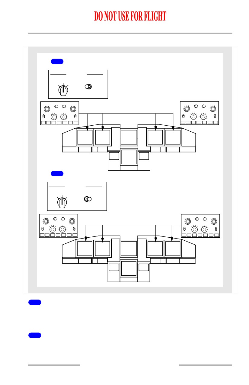
CONTROL PANEL Select Switch BOTH ON 1
The left EFIS control panel controls both pilots’ outboard and inboard display
units.
2
CONTROL PANEL Select Switch BOTH ON 2
The right EFIS control panel controls both pilots’ outboard and inboard display
units.
10.20.7
Flight Instruments, Displays -
EFIS/Map System Description
Boeing 737 Operations Manual
Outboard Display Switching
1
COMPACT
COMPACT
FORMAT
ENGINE
FORMAT
MAIN PANEL DUs
LOWER DU
LOWER DU
MAIN PANEL DUs
NORM
NORM
NORM
NORM
OUTBD
ENG
ENG
INOP
INOP
ENG
ENG
OUTBD
PFD
PRI
PRI
PRI
PRI
PFD
PFD
PFD
INBD
INBD
INOP
INOP
1
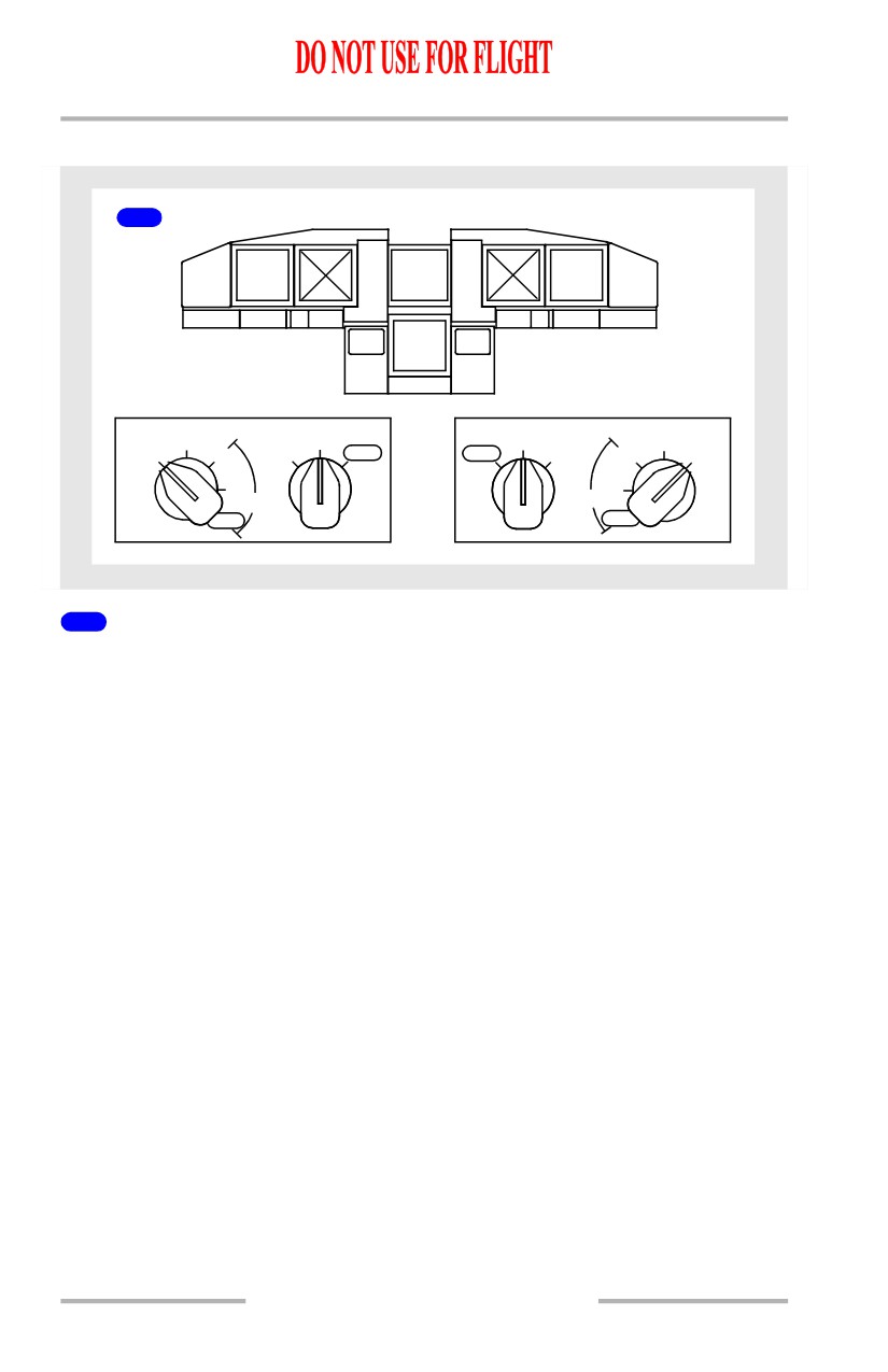
MAIN PANEL DUs Switch to OUTBD PFD
If the MAIN PANEL DUs switch is turned to Outboard Primary Flight Display
(OUTBD PFD), the compact EFIS format is displayed on the outboard display
unit and the inboard display unit blanks.
10.20.8
Flight Instruments, Displays -
EFIS/Map System Description
Boeing 737 Operations Manual
Inboard Display Switching
1
COMPACT
ENGINE
ENGINE
COMPACT
FORMAT
FORMAT
MAIN PANEL DUs
LOWER DU
LOWER DU
MAIN PANEL DUs
NORM
NORM
NORM
NORM
OUTBD
ENG
ENG
INOP
INOP
ENG
ENG
OUTBD
PFD
PRI
PRI
PRI
PRI
PFD
PFD
PFD
INBD
INBD
INOP
INOP
2
COMPACT
COMPACT
FORMAT
ENGINE
FORMAT
MAIN PANEL DUs
LOWER DU
LOWER DU
MAIN PANEL DUs
NORM
NORM
NORM
NORM
OUTBD
ENG
ENG
INOP
INOP
ENG
ENG
OUTBD
PFD
PRI
PRI
PRI
PRI
PFD
PFD
PFD
INBD
INBD
INOP
INOP
3
COMPACT
COMPACT
FORMAT
ENGINE
FORMAT
MAIN PANEL DUs
LOWER DU
LOWER DU
MAIN PANEL DUs
NORM
NORM
NORM
NORM
OUTBD
ENG
ENG
INOP
INOP
ENG
ENG
OUTBD
PFD
PRI
PRI
PRI
PRI
PFD
PFD
PFD
INBD
INBD
INOP
INOP
10.20.9
Flight Instruments, Displays -
EFIS/Map System Description
Boeing 737 Operations Manual
1
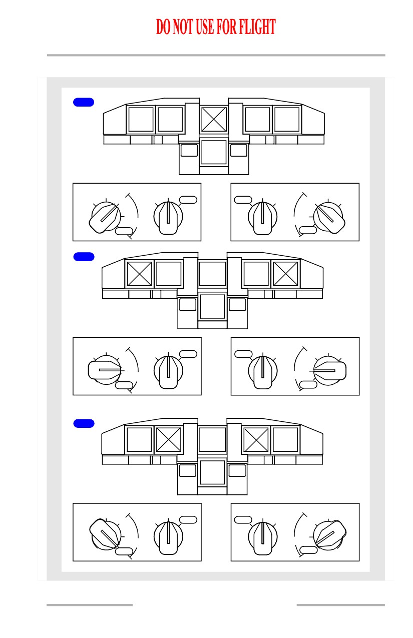
MAIN PANEL DUs Switch to INBD ENG PRI
If the MAIN PANEL DUs switch is turned to INBD ENG PRI, the engine display
moves to the inboard DU, the compact EFIS format is displayed on the outboard
DU and the upper DU blanks.
2
MAIN PANEL DUs Switch to INBD PFD
If the MAIN PANEL DUs switch is turned to INBD PFD the compact EFIS format
is displayed on the inboard DU and the outboard DU blanks.
3
MAIN PANEL DUs Switch to INOP
If the MAIN PANEL DUs switch is turned to INBD INOP the compact EFIS
format is displayed on the outboard DU and the inboard DU blanks.
10.20.10
Flight Instruments, Displays -
EFIS/Map System Description
Boeing 737 Operations Manual
Lower Display Switching
1
CAPT
CAPT
F/O
F/O
OUTBD
INBD
INBD
OUTBD
ENGINE
MAIN PANEL DUs
LOWER DU
LOWER DU
MAIN PANEL DUs
NORM
NORM
NORM
NORM
OUTBD
ENG
ENG
INOP
INOP
ENG
ENG
OUTBD
PFD
PRI
PRI
PRI
PRI
PFD
PFD
PFD
INBD
INBD
INOP
INOP
2
CAPT
CAPT
F/O
F/O
ENGINE
OUTBD
INBD
INBD
OUTBD
MAIN PANEL DUs
LOWER DU
LOWER DU
MAIN PANEL DUs
NORM
NORM
NORM
NORM
OUTBD
ENG
ENG
INOP
INOP
ENG
ENG
OUTBD
PFD
PRI
PRI
PRI
PRI
PFD
PFD
PFD
INBD
INBD
INOP
INOP
1
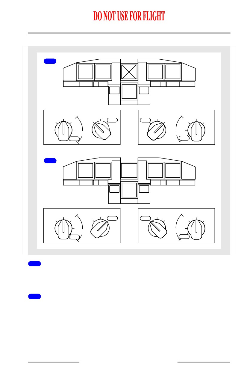
LOWER DU Switch to ENG PRI
If the LOWER DU switch is turned to ENG PRI, the engine display moves to the
lower DU and the upper DU blanks.
2
LOWER DU Switch to INOP
If the LOWER DU switch is turned to INOP the engine display is shown on the
upper DU and the lower DU blanks.
10.20.11
Flight Instruments, Displays -
EFIS/Map System Description
Boeing 737 Operations Manual
Display System Information Sources
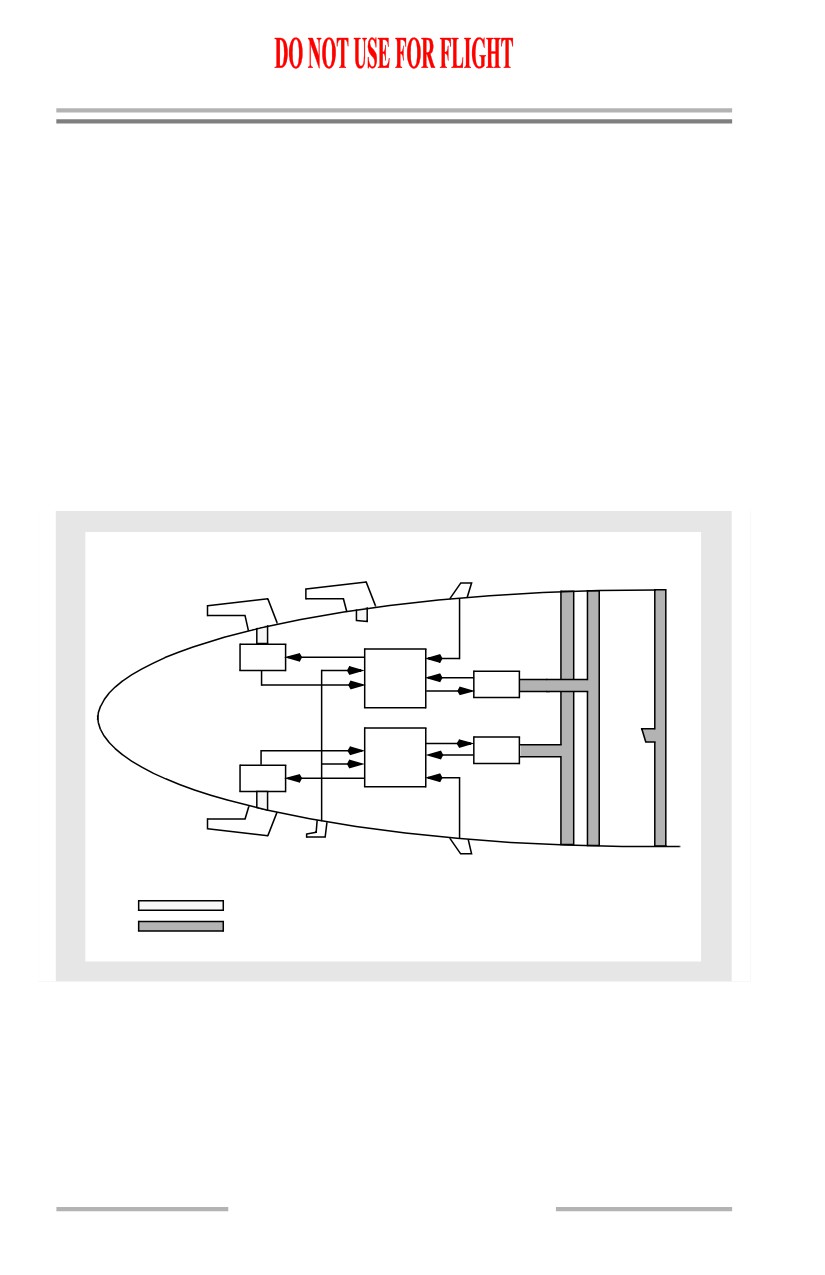
Air Data Inertial Reference System (ADIRS)
The ADIRS produces flight data such as position, speed, altitude and attitude for
the flight displays, flight management computers, flight controls, engine controls
and all other systems requiring inertial and air data.
The major components of the ADIRS are:
• two air data inertial reference
• six static ports
units (ADIRUs)
• three pitot probes
• four air data modules (ADMs)
• two alpha vanes
• one inertial system display unit
• one total air temperature probe
(ISDU)
• one dual mode select unit
(MSU)
AUXILIARY
ALPHA
CAPT
F/O
ALT
PITOT PROBE
VANE
STATIC
STATIC
STATIC
PORT
PORT
PORT
F/O PITOT PROBE
TO:STBY
AIRSPD
ADM
ADIRU-R
ADM
TO:
STBY
ADIRU-L
ADM
ALT/
AIRSPD
ADM
CAPT PITOT PROBE
TAT
PROBE
CAPT
F/O
ALT
ALPHA
STATIC
STATIC
STATIC
VANE
PORT
PORT
PORT
PITOT LINES
STATIC LINES
Air Data Inertial Reference Unit (ADIRU)
The ADIRUs provide inertial position and track data to the FMC as well as
attitude, altitude and airspeed data to the displays. The ADIRUs process
information measured by internal gyros and accelerometers, and from air data
module inputs, the alpha vanes and other systems.
The ADIRUs are described in Chapter 11, Flight Management, Navigation.
10.20.12
Flight Instruments, Displays -
EFIS/Map System Description
Boeing 737 Operations Manual
Air Data
The pitot static system is comprised of three separate pitot probes and six flush
static ports. Two pitot probes and four static ports interface with the air data
modules. The remaining auxiliary pitot probe and alternate static ports provide
pitot and static pressure to the standby instruments. The auxiliary pitot probe is
located on the first officer’s side of the airplane.
The air data modules convert pneumatic pressure to electrical signals and send
these data to the ADIRUs. Each pitot air data module is connected to its on-side
pitot probe; there is no cross connection. The air data module connected to the
Captain’s pitot probe sends information to the left ADIRU, while the air data
module connected to the First Officer’s pitot probe sends information to the right
ADIRU. The remaining air data modules are located at the balance centers of the
Captain’s and First Officer’s static ports. The air data module connected to the
Captain’s static ports sends information to the left ADIRU, while the air data
module connected to the First Officer’s static ports sends information to the right
ADIRU.
Angle-of-Attack
There are two alpha vanes, one located on each side of the forward fuselage. The
vanes measure airplane angle-of-attack relative to the air mass.
Total Air Temperature
A total air temperature probe is mounted outside the airplane to sense air mass
temperature. The temperature sensed by the probe is used by the ADIRUs to
compute total air temperature.
Static Air Temperature
Static air temperature, displayed on the CDU PROGRESS page, comes from the
ADIRUs, using total air temperature probe information.
Standby Flight Instruments
The standby flight instruments include:
• standby magnetic compass
• integrated standby flight
display
• standby radio magnetic
indicator
Standby Magnetic Compass
A standard liquid-damped magnetic standby compass is provided. A card located
near the compass provides heading correction factors.
10.20.13
Flight Instruments, Displays -
EFIS/Map System Description
Boeing 737 Operations Manual
Integrated Standby Flight Display (ISFD)
The ISFD displays attitude, airspeed, altitude, ILS, and heading information. It is
connected directly to the auxiliary pitot and alternate static sources. ILS
information is provided by the No. 1 ILS receiver. The display receives its heading
information from the same source as the captain’s primary flight display.
Note: The standby magnetic compass must be used to validate heading
information.
The battery bus powers the ISFD. Selecting the battery switch ON activates the
ISFD. After 10 seconds, an initialization sequence begins that requires 90 seconds
to complete. ATT and INIT 90s messages are displayed during initialization. Upon
completion of the initialization sequence, attitude information is displayed.
Note: Any change in airplane position during the initialization sequence may
result in an inaccurate alignment. Inaccurate alignment is not annunciated
and may result in the display of inaccurate attitude prior to, and during
flight. Re-initialization can only be accomplished through maintenance
action.
Detection of a momentary out-of-limit ISFD condition may cause the attitude
display to blank and the WAIT ATT or ATT:RST message to display. Operation of
the attitude reset switch is required in response to the ATT:RST message. This will
reset the horizon line with the airplane symbol.
Note: Operation of the attitude reset switch will not correct an inaccurate
alignment.
On the ground, operation of the attitude reset switch must be performed with the
airplane stationary. In flight, operation of the attitude reset switch must be
performed with the airplane in wings level, non-accelerated flight. During the
process, the ATT 10s message displays. Failure to maintain straight and level
flight for 10 seconds may result in an ATT:RST message. If the reset attempt is
unsuccessful, the ATT:RST message remains displayed and the ISFD does not
enter normal operation.
Standby Radio Magnetic Indicator
The standby radio magnetic indicator (RMI) displays magnetic heading and
VOR/ADF bearing to the station. The RMI is powered by the AC standby bus and
remains powered after the loss of all normal AC power as long as battery power
is available.
10.20.14
Flight Instruments, Displays -
EFIS/Map System Description
Boeing 737 Operations Manual
Clocks
[Option - Smiths 60B00303-105]
Two electronic clocks are installed, with two digital displays on each clock. Either
Greenwich Mean Time (GMT) or local time may be set on the upper time display.
The lower ET/CHR display is used for either elapsed time or the chronograph.
Separate controls are provided for each display.
Clock Switch
[Option - Remote clock switch]
A remote clock switch, on the glareshield panel, operates the same as the
chronograph (CHR) control.
Flight Recorder
The flight recorder provides a permanent record of selected operational and
systems information such as altitude, heading, acceleration, and airspeed. The
recorder is housed in a sealed, fire-resistant container located behind an access
door in the aft cabin ceiling.
Operational and systems information is automatically recorded whenever the
flight recorder is powered. On the ground, the recorder begins operating when one
of the engines is operating. In the air, the flight recorder is powered even with both
engines shut down as long as APU electrical power is available.
Aircraft Condition Monitoring System (ACMS)
[Option]
The DFDAU receives signals representing certain flight condition and airplane
systems’ operating performance and converts them to a digital form for recording
on the DFDR.
The DFDR records airplane systems and flight data for at least the last 25 hours
of operation. The DFDR is located in the aft fuselage area.
[Option - Quick Access Recorder (QAR) lights]
A indicator on the Aft Overhead Panel illuminates when the quick access recorder
is full. The QAR is located in the electronics equipment bay.
10.20.15
Flight Instruments, Displays -
EFIS/Map System Description
Boeing 737 Operations Manual
Intentionally
Blank
10.20.16
Boeing 737 Operations Manual
Flight Instruments, Displays
Chapter 10
PFD/ND System Description
Section 21
Introduction
The common display system (CDS) supplies information to the flight crew on six
flat panel liquid crystal display units (DUs). The outboard and inboard display
units present all primary flight and navigation information. Primary engine
indications are normally displayed on the upper DU. Secondary engine indications
or system data are normally displayed on the lower DU.
Detailed information on the following subjects is found in other sections of this
chapter:
• Primary Flight Display (PFD)- Section 31
• Navigation display (ND)- Section 41.
Display Brightness Control
Adjustment of the brightness of each DU is controlled by a combination of light
sensors and brightness controls. Two remote light sensors, located left and right
on the top of the glareshield, compensate for the amount of ambient light entering
through the flight deck windows and adjust the brightness of the related DUs.
Each DU also has an integral light sensor which provides automatic control of
brightness as a function of ambient light striking the face of the DU. Brightness
controls are used by the pilot to further adjust the intensity of each display unit.
10.21.1
Flight Instruments, Displays -
PFD/ND System Description
Boeing 737 Operations Manual
DISPLAYS SOURCE Panel
DISPLAYS
SOURCE
CONTROL PANEL
AUTO
ALL
ALL
ON 1
ON 2
BOTH
BOTH
ON 1
ON 2
NORMAL
CAPT
CAPT
F/O
F/O
ENGINE
OUTBD
INBD
INBD
OUTBD
DEU 1
DEU 2
AIRPLANE SENSORS AND SYSTEMS
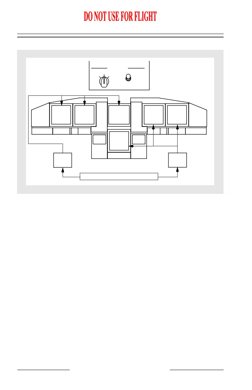
The DISPLAYS source panel, located on the forward overhead panel, contains
source controls for the display electronic units (DEUs) and EFIS control panels.
Two DEUs receive data from sensors and airplane systems and supply data to the
DUs. During normal operation, with the display SOURCE selector switch in the
AUTO position, DEU1 supplies data to the Captain outboard, Captain inboard and
upper DUs while DEU2 supplies data to the First Officer outboard, First Officer
inboard and lower DUs. If a DEU fails, the remaining DEU automatically supplies
data to all six displays. This prevents the loss of navigation information.
The display SOURCE selector, used on the ground for maintenance purposes,
allows manual selection of either DEU1 or DEU2 for all six display units. If the
displays are automatically or manually switched to a single DEU source, a
“DSPLY SOURCE” annunciation illuminates on both pilot’s primary flight
display.
The CONTROL PANEL select switch determines which EFIS control panel
controls the pilots’ display functions. With the switch positioned to either BOTH
ON 1 or BOTH ON 2, the selected EFIS control panel provides inputs for both sets
of pilot displays. When in the NORMAL position, a “DISPLAYS CONTROL
PANEL” annunciation illuminates below the altitude indication showing a failure
of the associated EFIS control panel.
10.21.2
Flight Instruments, Displays -
PFD/ND System Description
Boeing 737 Operations Manual
EFIS Control Panels
The EFIS control panels, located on the glareshield, controls display options,
mode, and range for the related pilot’s displays. Refer to the PFD and ND sections
of this chapter for detailed information.
If an EFIS control panel fails, the displays can be controlled by the remaining
control panel.
Display Select Panel
The display select panel, located on the left and right forward panels, controls the
displays on the inboard, outboard and lower DUs. Normal operation is all selectors
in the NORMAL position. The pilots’ outboard and inboard DUs display primary
flight and navigation data and the upper DU displays primary engine data and fuel
quantity.
If a DU fails, automatic display switching ensures critical information remains
available to the pilots at all times. If the system detects an operational failure on
an outboard DU, the primary flight display automatically moves to the inboard
DU and the failed outboard DU blanks. The OUTBD/INDB selector no longer has
control over that display unit. If the upper DU fails, the engine display
automatically moves to the lower DU.
Manual control of display formats is provided for undetected failures. The
outboard rotary switch on the display select panel controls the formats displayed
on either the outboard or inboard DUs. The inboard rotary switch controls the
display format shown on the lower DU.
10.21.3
Flight Instruments, Displays -
PFD/ND System Description
Boeing 737 Operations Manual
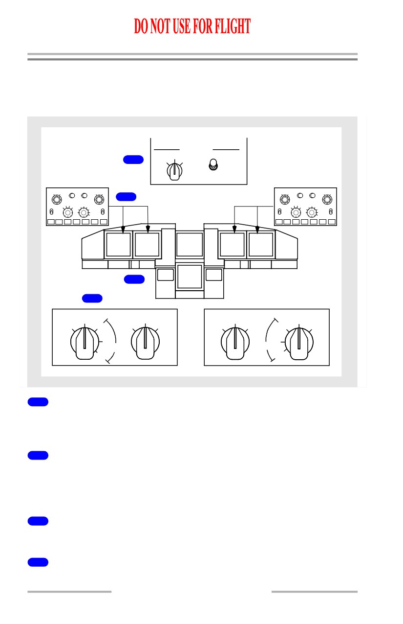
Display Selection and Control Examples
The following examples show display selections.
Normal Display Configuration
DISPLAYS
SOURCE
CONTROL PANEL
AUTO
1
ALL
ALL
ON 1
ON 2
BOTH
BOTH
ON 1
ON 2
NORMAL
MINS
RADIO BAROF
PV
MTRS
BARO
IN HPA
MINS
RADIO BAROF
PV
MTRS
BAROIN HPA
RST
STD
2
RST
STD
VOR1
APP
VOR MAP
PLN
2040
80
VOR2
VOR1
APPVOR MAP
PLN
2040
80
VOR2
10
160
10
160
OFF
CTR
5
TFC
320
OFF
OFF
CTR
5
TFC
320
OFF
ADF1
640
ADF2
ADF1
640
ADF2
WXR STA WPT ARPT DATA POS TERR
WXR STA WPT ARPT DATA POS TERR
CAPT
CAPT
F/O
F/O
ENGINE
OUTBD
INBD
INBD
OUTBD
4
3
MAIN PANEL DUs
LOWER DU
LOWER DU
MAIN PANEL DUs
NORM
NORM
NORM
NORM
OUTBD
ENG
ENG
ND
ND
ENG
ENG
OUTBD
PFD
PRI
PRI
PRI
PRI
PFD
PFD
PFD
INBD
INBD
MFD
MFD
1
DISPLAYS Source Panel
The display SOURCE select switch is in AUTO and the CONTROL PANEL
select switch is in NORMAL.
2
EFIS Control Panel
The left EFIS control panel controls the Captain outboard and inboard display
units. The right EFIS control panel controls the First Officer outboard and inboard
display units.
3
Display Select Panel
All selectors are in NORMAL.
4
Display Units
The pilots’ outboard and inboard DUs show the normal PFD/ND displays.
10.21.4
Flight Instruments, Displays -
PFD/ND System Description
Boeing 737 Operations Manual
Display Unit Failure Automatic Switching
1
PFD
ENGINE
ND
PFD
2
CAP
PFD
ND
ENGINE
PFD
3
PFD
ND
ND
PFD
ENGINE
MAIN PANEL DUs
LOWER DU
LOWER DU
MAIN PANEL DUs
NORM
NORM
NORM
NORM
OUTBD
ENG
ENG
ND
ND
ENG
ENG
OUTBD
PFD
PRI
PRI
PRI
PRI
PFD
PFD
PFD
INBD
INBD
MFD
MFD
1
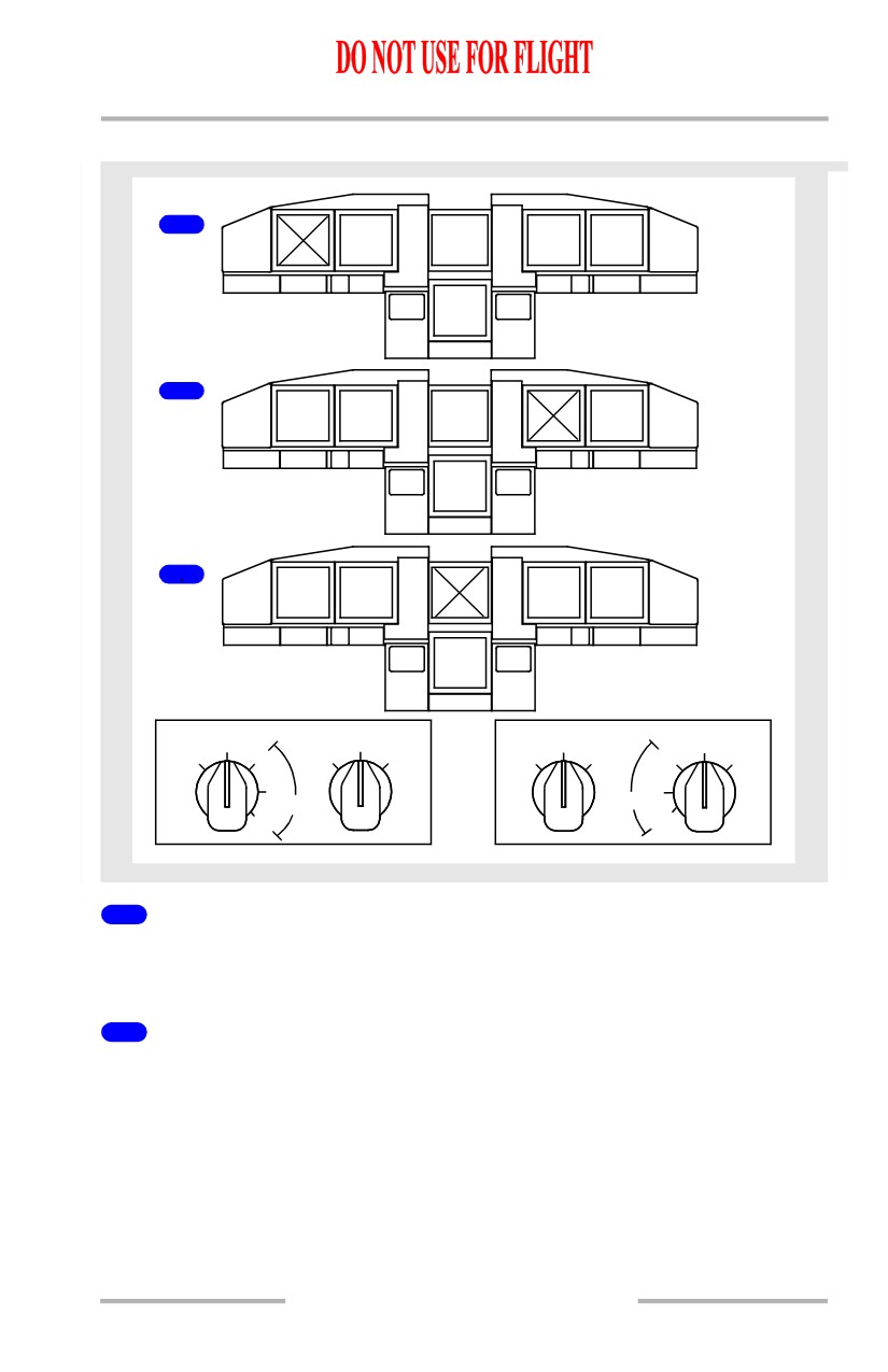
Outboard Display Unit Fails
If an outboard display unit fails, the PFD is automatically displayed on the inboard
display unit and the outboard display unit blanks.
2
Inboard Display Unit Fails
If an inboard display unit fails, the PFD format remains displayed on the outboard
display unit and the inboard display unit blanks.
10.21.5
Flight Instruments, Displays -
PFD/ND System Description
Boeing 737 Operations Manual
3
Upper Display Unit Fails
If the upper display unit fails, the primary engine display automatically moves to
the lower display unit and the upper display unit blanks. If the secondary engine
display is already on the lower display unit, a compact engine display is then
displayed.
Note: There is no automatic switching for a lower DU failure.
10.21.6
Flight Instruments, Displays -
PFD/ND System Description
Boeing 737 Operations Manual
EFIS Control Panel
1
DISPLAYS
SOURCE
CONTROL PANEL
AUTO
ALL
ALL
ON 1
ON 2
BOTH
BOTH
ON 1
ON 2
NORMAL
MINS
RADIO BAROF
PV
MTRS
BAROIN HPA
MINS
RADIO BAROF
PV
MTRS
IN
BARO
HPA
RST
STD
RST
STD
VOR1
APP
VOR MAP
PLN
2040
80
VOR
2
VOR1
APP
VOR MAP
PLN
2040
80
VOR2
10
160
10
160
OFF
CTR
5
TFC
320
OFF
OFF
CTR
5
TFC
320
OFF
ADF1
640
ADF2
ADF1
640
ADF2
WXR STA WPT ARPT DATA POS TERR
WXR STA WPT ARPT DATA POS TERR
CAPT
CAPT
F/O
F/O
ENGINE
OUTBD
INBD
INBD
OUTBD
2
DISPLAYS
SOURCE
CONTROL PANEL
AUTO
ALL
ALL
ON 1
ON 2
BOTH
BOTH
ON 1
ON 2
NORMAL
MINS
RADIO BAROF
PV
MTRS
BAROIN HPA
MINS
RADIO BAROF
PV
MTRS
BAROIN HPA
RST
STD
RST
STD
VOR1
APPVOR MAP
PLN
2040
80
160
VOR2
VOR1
APP
VOR MAP
PLN
2040
80
160
VOR2
OFF
CTR
105
TFC
320
OFF
OFF
CTR
5
10
TFC
320
OFF
ADF1
640
ADF2
ADF1
640
ADF2
WXR STA WPT ARPT DATA POS TERR
WXR STA WPT ARPT DATA POS TERR
CAPT
CAPT
ENGINE
F/O
F/O
OUTBD
INBD
INBD
OUTBD
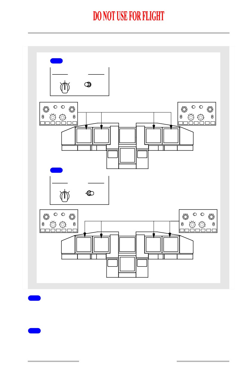
1
CONTROL PANEL Select Switch BOTH ON 1
The left EFIS control panel controls both pilots’ outboard and inboard display
units.
2
CONTROL PANEL Select Switch BOTH ON 2
The right EFIS control panel controls both pilots’ outboard and inboard display
units.
10.21.7
Flight Instruments, Displays -
PFD/ND System Description
Boeing 737 Operations Manual
Outboard Display Switching
1
PFD
ENGINE
PFD
MAIN PANEL DUs
LOWER DU
LOWER DU
MAIN PANEL DUs
NORM
NORM
NORM
NORM
ENG
ND
ND
ENG
OUTBD
OUTBD
ENG
ENG
PFD
PRI
PRI
PRI
PRI
PFD
PFD
PFD
INBD
INBD
MFD
MFD
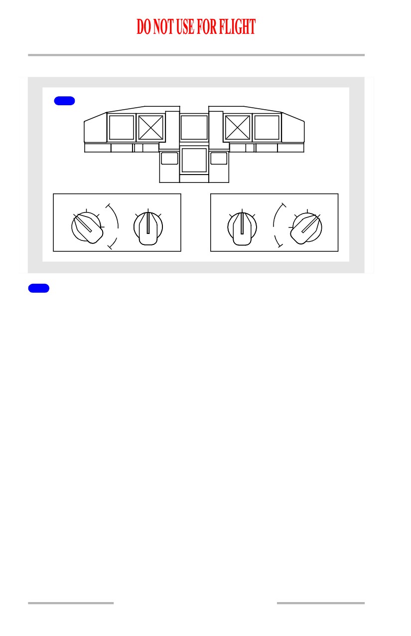
1
MAIN PANEL DUs Switch to OUTBD PFD
If the MAIN PANEL DUs switch is turned to Outboard Primary Flight Display
(OUTBD PFD), the PFD format is displayed on the outboard display unit and the
inboard display unit blanks.
10.21.8
Flight Instruments, Displays -
PFD/ND System Description
Boeing 737 Operations Manual
Inboard Display Switching
1
PFD
ENGINE
ENGINE
PFD
MAIN PANEL DUs
LOWER DU
LOWER DU
MAIN PANEL DUs
NORM
NORM
NORM
NORM
OUTBD
ENG
ENG
ND
ND
ENG
ENG
OUTBD
PFD
PRI
PRI
PRI
PRI
PFD
PFD
PFD
INBD
INBD
MFD
MFD
2
PFD
ENGINE
PFD
MAIN PANEL DUs
LOWER DU
LOWER DU
MAIN PANEL DUs
NORM
NORM
NORM
NORM
OUTBD
ENG
ENG
ND
ND
ENG
ENG
OUTBD
PFD
PRI
PRI
PRI
PRI
PFD
PFD
PFD
INBD
INBD
MFD
MFD
10.21.9