Boeing 737 - 600/700/800/900. Operations Manual (1997 year) - page 48
Flight Instruments, Displays -
EFIS Instruments - Controls and
Indicators
Boeing 737 Operations Manual
4
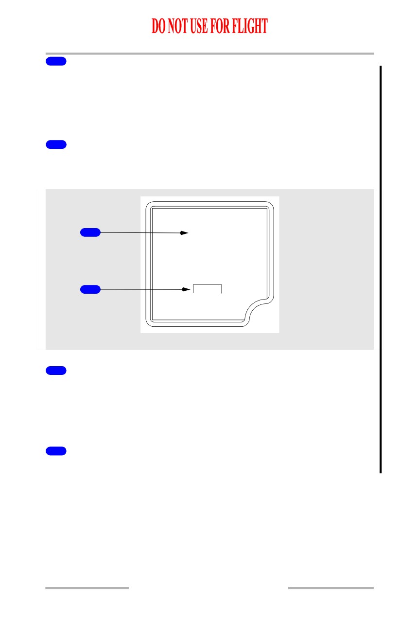
Display Brightness Switches
Push -
•
+ increases display brightness
•
- decreases display brightness
5
Airplane Symbol
Indicates airplane attitude with reference to the horizon.
6
Airspeed Indications
Indicates current airspeed when above 30 knots.
7
Attitude Reset (ATT RST) Switch
Push and hold at least two seconds
• aligns horizon with the airplane symbol
• reset takes approximately ten seconds
8
Hectopascal/Inch (HP/IN) Switch
Push - changes the units of the barometric reference.
9
Barometric Setting
Indicates the barometric setting selected with the barometric selector.
STD is displayed when selected with the barometric selector.
10
Ambient Light Sensor
Automatically adjusts display intensity for ambient lighting condition.
11
Glideslope Pointer and Deviation Scale
The glideslope pointer indicates glideslope position relative to the airplane.
• the pointer is in view when the glideslope signal is received
• the scale is in view when the APP mode is selected
• the pointer and scale are removed when the BCRS mode is selected
12
Current Altitude
13
Localizer Pointer and Deviation Scale
The localizer pointer indicates localizer position relative to the airplane.
• the pointer is in view when the localizer signal is received
• the scale is in view when either the APP or BCRS mode is selected
10.15.12
Flight Instruments, Displays -
EFIS Instruments - Controls and
Indicators
Boeing 737 Operations Manual
14
Barometric (BARO) Selector
Rotate - changes barometric setting
Push -
• selects standard barometric setting (29.92 inches Hg/1013 HPA)
• if STD is displayed, selects the preselected barometric setting
15
Heading Indication
Displays airplane heading.
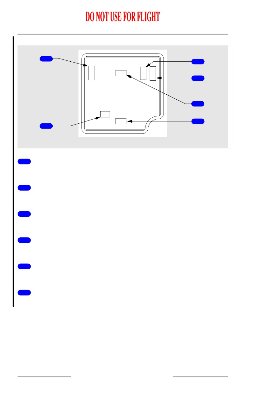
ISFD Messages
1
WAIT ATT
2
INIT 90s
ISFD
1
Attitude Messages
Indicates attitude display status.
• ATT:RST (amber) - attitude must be reset using the attitude reset switch
• ATT 10s (amber) - 10 second attitude realignment in progress
• WAIT ATT (amber) - indicates temporary self correcting loss of attitude
2
Initialization Message
INIT 90s (amber) - 90 second initialization in progress.
10.15.13
Flight Instruments, Displays -
EFIS Instruments - Controls and
Indicators
Boeing 737 Operations Manual
ISFD Failure Flags
1
3
S
G
A
P
ATT
/
L
D
S
T
4
5
LOC
HDG
6
2
ISFD
1
Airspeed flag
Airspeed information has failed.
2
ILS localizer failure flag
ILS localizer has failed.
3
ILS glideslope failure flag
ILS glideslope has failed.
4
Altitude flag
Altitude information has failed.
5
Attitude flag
Attitude information has failed.
6
Heading flag
Heading data has failed.
10.15.14
Flight Instruments, Displays -
EFIS Instruments - Controls and
Indicators
Boeing 737 Operations Manual
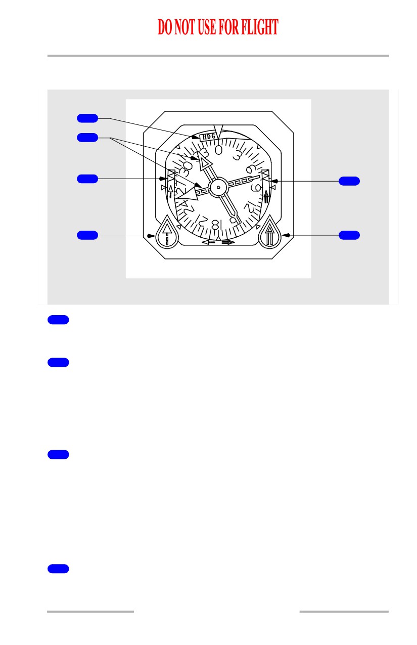
Standby Radio Magnetic Indicator
[Option - Dual ADF]
1
2
3
5
V
V
O
O
R
R
4
6
ADF
ADF
CENTER FORWARD PANEL
1
Heading Warning Flag
The compass signal from the air data inertial reference system is lost.
2
Bearing Pointers
• narrow pointer uses signals from the VHF NAV receiver No. 1 or ADF
receiver No. 1.
[Option - Dual ADF]
• wide pointer uses signals from the VHF NAV receiver No. 2 or ADF
receiver No. 2.
3
Bearing Pointer No. 1 Warning Flag
VOR mode:
• RMI power failure
• VHF NAV signal unreliable.
ADF mode:
• RMI power failure
• ADF failure or signal unreliable.
4
VOR/ADF Bearing Pointer No. 1 Switch
ROTATE - selects VOR or ADF for the bearing pointer.
10.15.15
Flight Instruments, Displays -
EFIS Instruments - Controls and
Indicators
Boeing 737 Operations Manual
5
Bearing Pointer No. 2 Warning Flag
VOR mode
• RMI power failure
• VHF NAV signal unreliable.
[Option - Dual ADF]
ADF mode
• RMI power failure
• ADF failure or signal unreliable.
6
VOR/ADF Bearing Pointer No. 2 Switch
[Option - Dual ADF]
ROTATE - selects VOR or ADF for the bearing pointer.
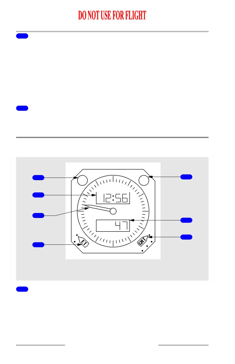
Clock
[Option - Smiths 60B00303-105]
CHR
DATE
1
5
60
DAY MO / YEAR
2
50
10
GMT
3
ET/CHR
6
40
20
RUN
RUN
30
7
HLD
HL
Y
SSM
4
FSD
RESET
LEFT and RIGHT FORWARD
PANELS
1
Chronograph (CHR) Control
PUSH -
• controls the start, stop and reset functions of the CHR display and second
hand with successive pushing
• overrides any existing ET display.
10.15.16
Flight Instruments, Displays -
EFIS Instruments - Controls and
Indicators
Boeing 737 Operations Manual
2
Time/Date Window
• displays time (hours, minutes) when time is selected with the date control
• alternately displays day-month and year when date is selected with the
date control.
3
Chronograph Second Hand
• indicates chronograph seconds
• controlled by the CHR control
4
Elapsed Time (ET) Selector (three position, rotary)
Controls the elapsed time function.
RESET - returns ET display to zero (spring loaded to HLD).
HLD (hold) - stops the elapsed time display.
RUN - starts the elapsed time display.
5
Date Control
Controls the date display.
PUSH - displays date (day, month) alternating with year.
PUSH - returns display to time.
6
Elapsed Time (ET)/Chronograph Window
• displays elapsed time (hours, minutes) or chronograph minutes
• the chronograph display replaces the elapsed time display
• elapsed time continues to run in the background and displays after the
chronograph is reset.
7
Time Control (four position, rotary)
Sets the time and date when the time or date is selected with the date control.
FS D (fast slew, day) -
• advances hours when time is selected with the date control
• advances days when date is selected with the date control.
SS M (slow slew, month) -
• advances minutes when time is selected with the date control
• advances months when date is selected with the date control.
HLD Y (hold, year) -
• stops the time indicator and sets the seconds to zero when time is selected
with the date control
• advances years when date is selected with the date control.
10.15.17
Flight Instruments, Displays -
EFIS Instruments - Controls and
Indicators
Boeing 737 Operations Manual
RUN - starts the time indicator.
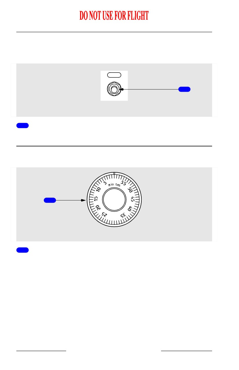
Clock Switch
[Option]
CLOCK
1
GLARESHIELD PANEL
1
Clock Switch
Operates the same as the chronograph (CHR) control.
Timer
[Option]
0
u
1
AFT OVERHEAD PANEL
1
Mechanical Timer
10.15.18
Flight Instruments, Displays -
EFIS Instruments - Controls and
Indicators
Boeing 737 Operations Manual
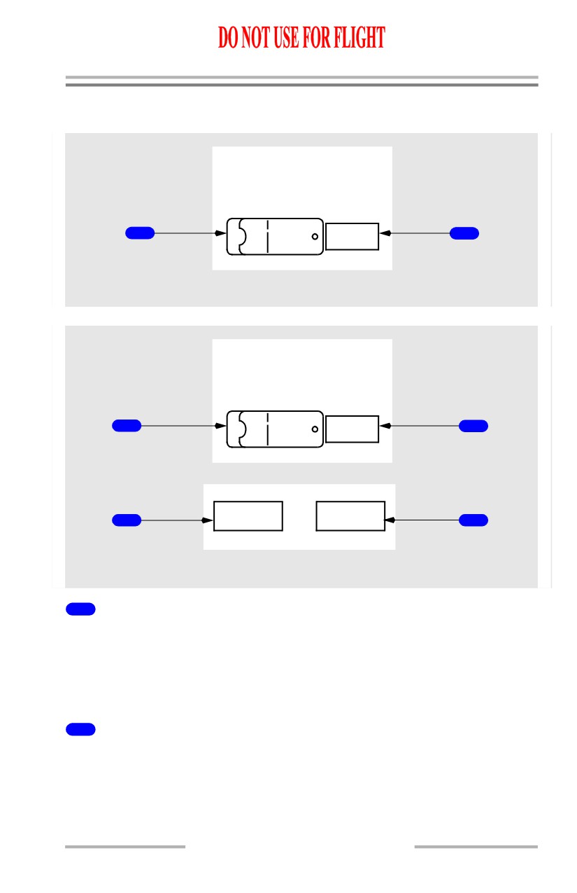
Flight Recorder
[Option - Without QAR lights]
FLIGHT RECORDER
TEST NORMAL
1
OFF
2
AFT OVERHEAD PANEL
[Option - With QAR lights]
FLIGHT RECORDER
TEST NORMAL
1
OFF
2
OQAR
OQAR FAIL
3
DISC FULL
4
AFT OVERHEAD PANEL
1
Flight Recorder Test Switch
NORMAL (guarded position) -
• inflight - the recorder operates anytime electrical power is available
• on the ground - either engine must also be operating.
TEST - powers the flight recorder on the ground.
2
OFF Light (amber)
ILLUMINATED -
• indicates the recorder is not operating or the test is invalid
• may indicate power failure, loss of input data, or electronic malfunction.
10.15.19
Flight Instruments, Displays -
EFIS Instruments - Controls and
Indicators
Boeing 737 Operations Manual
3
Optical Quick Access Recorder (OQAR) Disc Full (blue)
[Option - QAR lights]
ILLUMINATED -
• indicates the quick access recorder is full
4
Optical Quick Access Recorder (OQAR) FAIL (blue)
[Option - QAR lights]
ILLUMINATED -
• indicates the quick access recorder has failed
10.15.20
Boeing 737 Operations Manual
Flight Instruments, Displays
Chapter 10
EFIS Instruments (PFD) - Controls
Section 16
EFIS Control Panel (PFD/ND Display)
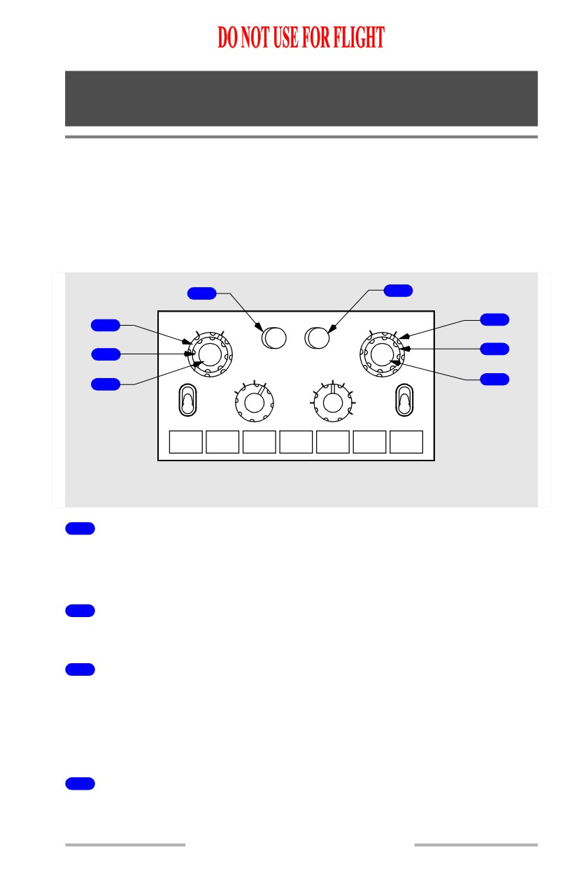
The left EFIS control panel controls the Captain outboard and inboard display
units. The right EFIS control panel controls the First Officer outboard and inboard
display units.
EFIS Control Panel Controls - Flight Instrument Displays
[Option - Dual ADF]
8
4
FPV
MTRS
BARO
5
1
RADIOMINS BARO
IN
HPA
6
2
RST
STD
MAP
40
VOR 1
VOR
PLN
20
80
VOR 2
7
3
APP
10
160
OFF
OFF
CTR
5
TFC
320
640
ADF 1
ADF 2
WXR
STA
WPT
ARPT
DATA
POS
TERR
GLARESHIELD
1
Minimums (MINS) Reference Selector (outer) (two position)
RADIO - selects radio altitude as the minimums reference
BARO - selects barometric altitude as the minimums reference.
2
Minimums (MINS) Selector (middle) (slew)
ROTATE - adjusts the radio or baro minimums altitude.
3
Radio Minimums (MINS) Reset (RST) Switch (inner) (momentary
action)
PUSH -
• resets the alert minimums annunciation
• blanks minimums display if alert is not active.
4
Meters (MTRS) Switch (momentary action)
PUSH - displays altitude indications in meters.
10.16.1
Flight Instruments, Displays -
EFIS Instruments (PFD) -
Controls
Boeing 737 Operations Manual
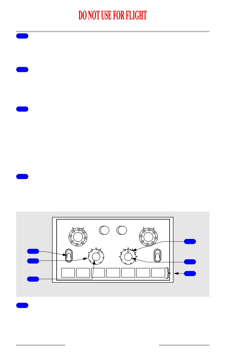
5
Barometric (BARO) Reference Selector (outer) (two position)
IN - selects inches of mercury as the barometric altitude reference
HPA - selects hectopascals as the barometric altitude reference.
6
Barometric (BARO) Selector (middle) (slew)
ROTATE -
• adjusts the barometric altitude setting on the altitude tape
• if STD displayed, adjusts the preselected BARO reference.
7
Barometric (BARO) Standard (STD) Switch (inner) (momentary
action)
PUSH -
• selects the standard barometric setting (29.92 inches Hg/1013 HPA) for
barometric altitude reference
• if STD is displayed, selects the preselected barometric reference
• if no preselected barometric is displayed, displays the last value before
STD was selected.
8
Flight Path Vector (FPV) Switch (momentary action)
PUSH - displays flight path vector on the attitude indicator.
EFIS Control Panel Controls - Navigation Displays
[Option - Dual ADF]
FPV
MTRS
BARO
RADIOMINS BARO
IN
HPA
RST
STD
4
MAP
40
VOR 1
VOR
PLN
20
80
VOR 2
APP
10
160
1
OFF
OFF
CTR
5
TFC
320
2
640
5
ADF 1
ADF 2
WXR
STA
WPT
ARPT
DATA
POS
TERR
6
3
GLARESHIELD
1
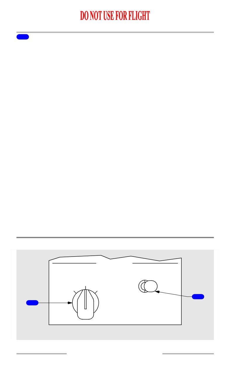
VOR/ADF Switch (three position)
Displays VOR or ADF information on all navigation modes except PLAN.
VOR - displays the selected VOR bearing pointer, frequency or identification and
DME.
10.16.2
Flight Instruments, Displays -
EFIS Instruments (PFD) -
Controls
Boeing 737 Operations Manual
OFF - removes the VOR or ADF displays.
ADF - displays the selected ADF pointer and ADF frequency or identification.
2
Mode Selector (outer)
Selects the desired display.
APP -
• displays localizer and glideslope information in heading-up format
• displays reference ILS receiver, ILS frequency or identification, course
and DME
• weather radar and TCAS are not displayed in center APP mode.
VOR -
• displays VOR navigation information in heading-up format
• displays reference VOR receiver, VOR frequency or identification,
course, DME and TO/FROM information
• weather radar and TCAS are not displayed in center VOR mode.
MAP -
[Option - Track-up display]
• displays FMC generated route and MAP information, airplane position,
heading and track, in a track-up format
• displays waypoints, including the active waypoint, within the selected
range
• displays VNAV path deviation.
PLN -
• displays a non-moving, true north up, route depiction
• the airplane symbol represents actual airplane position and orientation
• allows route step-through using the CDU LEGS page
• weather radar and TCAS are not displayed.
3
Center (CTR) Switch (inner)
PUSH -
• displays the full compass rose (center) for APP, VOR and MAP modes
• subsequent pushes alternate between expanded and center displays.
4
Range Selector (outer)
Selects desired display range in nautical miles for APP, VOR, MAP or PLN mode.
5
Traffic (TFC) Switch (inner)
PUSH - displays TCAS information on the navigation display (refer to Chapter
15, Warning Systems).
10.16.3
Flight Instruments, Displays -
EFIS Instruments (PFD) -
Controls
Boeing 737 Operations Manual
6
MAP Switches (momentary action)
The MAP switches:
• add background data/symbols to MAP and center MAP modes
• displays can be selected simultaneously
• second push removes the information.
WXR (weather radar) - energizes weather radar transmitter and displays weather
radar returns in MAP, center MAP, expanded VOR and expanded APP modes.
When the 640 nm range is selected, weather radar returns are limited to 320 nm
(refer to Chapter 11, Flight Management, Navigation).
STA (station) -
• displays all FMC data base navigation aids if on map scales 5, 10, 20 or
40 nm
• displays FMC data base high altitude navigation aids on map scales 80,
160, 320 or 640 nm.
WPT (waypoint) - displays the waypoints in the FMC data base which are not in
the flight plan route if the selected range is 40 nm or less.
ARPT (airport) - displays all airports which are stored in the FMC data base and
which are within the viewable map area.
DATA - displays altitude constraint, if applicable, and estimated time of arrival
for each active route waypoint.
POS (position) - displays IRS positions, GPS positions and VOR bearing vectors
extended from the nose of the airplane symbol to the stations.
TERR (terrain) - displays GPWS generated terrain data in MAP, center MAP,
VOR, and APP modes (refer to Chapter 15, Warning Systems).
Displays Source Panel
DISPLAYS
SOURCE
CONTROL PANEL
AUTO
BOTH
BOTH
ALL
ALL
ON 1
ON 2
ON 1
ON 2
NORMAL
2
1
FORWARD OVERHEAD PANEL
10.16.4
Flight Instruments, Displays -
EFIS Instruments (PFD) -
Controls
Boeing 737 Operations Manual
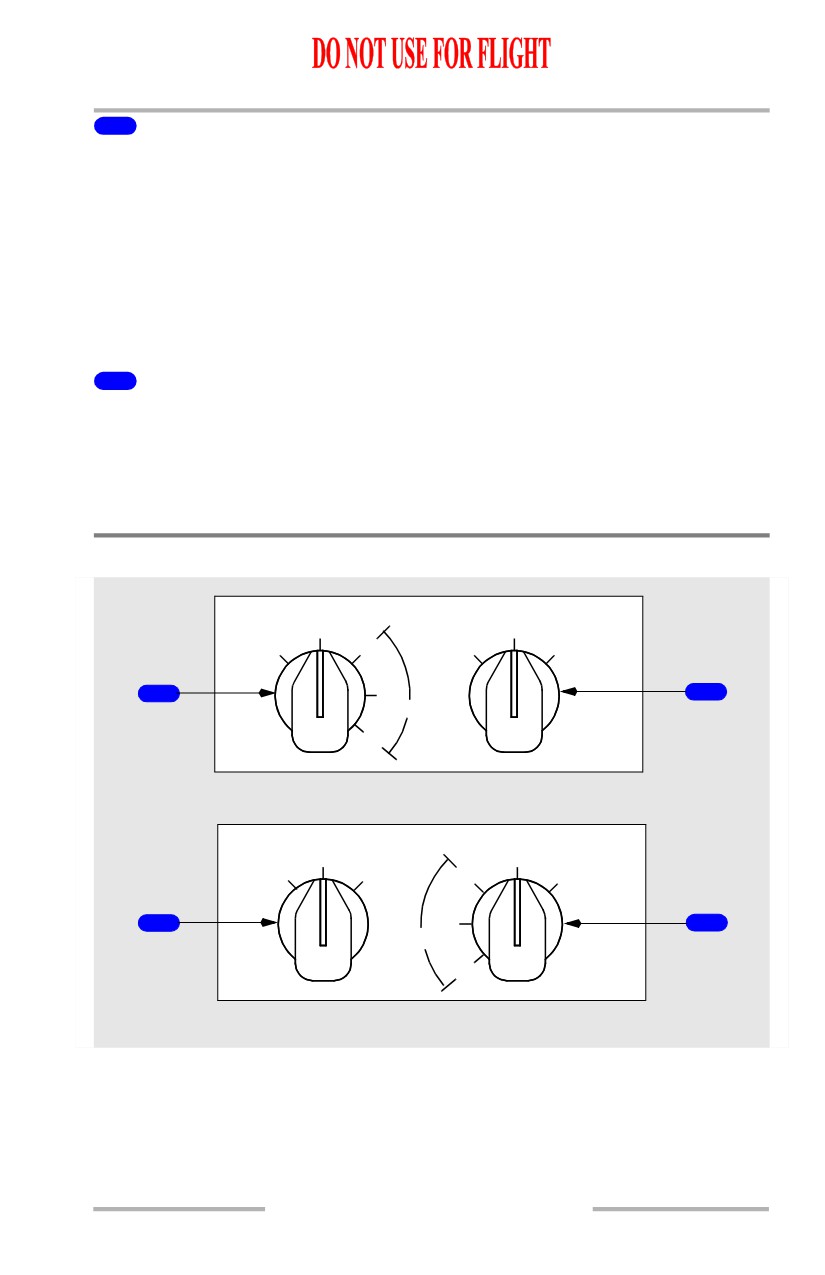
1
DISPLAYS SOURCE Selector
AUTO - DEU 1 controls the Captain outboard, Captain inboard, and the upper
display units; DEU 2 controls the First Officer outboard, First Officer inboard, and
the lower display units. When a DEU fails, the other DEU controls all display
units.
ALL ON 1/ALL ON 2 - provides a means of manually switching to a single DEU
as the source of information for all six display units.
Note: Used on the ground for maintenance purposes.
2
CONTROL PANEL Select Switch
NORMAL - the left EFIS control panel controls the Captain’s displays and the
right EFIS control panel controls the First Officer’s displays.
BOTH ON 1/BOTH ON 2 - provides a means of manually switching control of
the Captain’s and First Officer’s displays to a single EFIS control panel.
Display Select Panels
MAIN PANEL DUs
LOWER DU
NORM
NORM
OUTBD
ENG
ND
PFD
PRI
ENG
PRI
1
2
PFD
INBD
MFD
LEFT FORWARD PANEL
LOWER DU
MAIN PANEL DUs
NORM
NORM
ND
ENG
ENG
OUTBD
PRI
PRI
PFD
2
PFD
1
INBD
MFD
RIGHT FORWARD PANEL
10.16.5
Flight Instruments, Displays -
EFIS Instruments (PFD) -
Controls
Boeing 737 Operations Manual
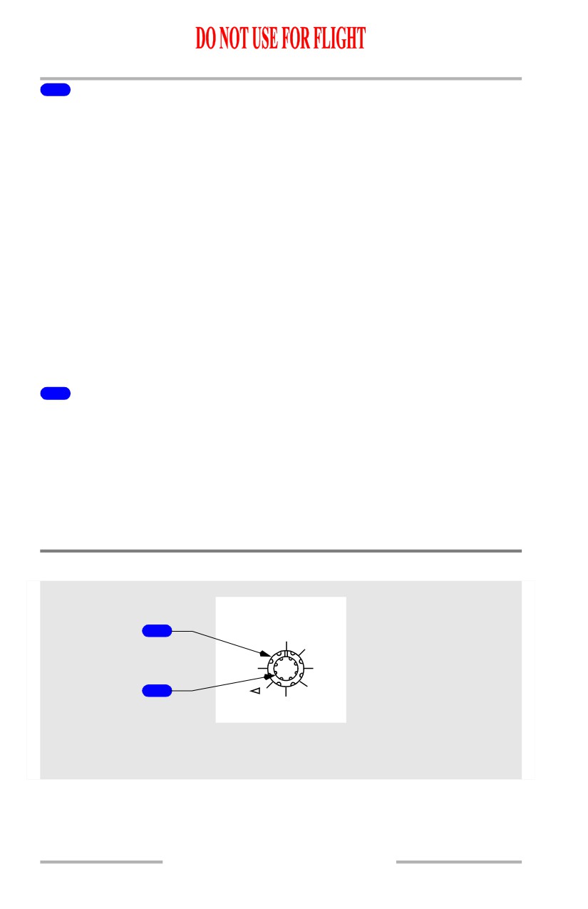
1
Main Panel Display Units (MAIN PANEL DUs) Selector
Selects what is displayed on the respective outboard and inboard display units:
• Outboard Primary Flight Display (OUTBD PFD) - displays the PFD on
the outboard display unit and blanks the inboard display unit
• Normal (NORM) - displays PFD on the outboard display unit and ND on
the inboard display unit
• Inboard Engine Primary (INBD ENG PRI) - displays the primary engine
instruments on the inboard display unit and the PFD on the outboard
display unit
• Inboard Primary Flight Display (INBD PFD) - displays the PFD on the
inboard display unit and blanks the outboard display unit
• Inboard Multifunction Display (INBD MFD) - displays PFD on the
outboard display unit and blanks the inboard display unit. The inboard
display unit stays blank until system format (SYS) or secondary engine
format (ENG) is selected with MFD switches on the engine display
control panel.
2
Lower Display Unit (LOWER DU) Selector
Selects what is displayed on the lower display unit:
• Engine Primary (ENG PRI) - displays the primary engine instruments on
the lower display unit and blanks the upper display unit
• Normal (NORM) - display unit is normally blank or displays MFD
format selected on the engine display control panel
• Navigation Display (ND) - displays the navigation display on the lower
unit.
Speed Reference Selector
SPD REF
1
AUTO
V1
SET
VR
2
WT
REF
V
CENTER FORWARD
PANEL
10.16.6
Flight Instruments, Displays -
EFIS Instruments (PFD) -
Controls
Boeing 737 Operations Manual
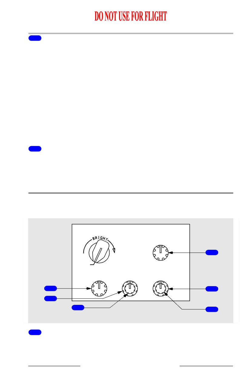
1
Speed Reference Selector (outer)
Sets the reference airspeed bugs on the airspeed indication:
• AUTO - the reference airspeeds and gross weight are provided
automatically through the FMC
• V1 - used to manually set decision speed on the ground; in flight, displays
“INVALID ENTRY”
• VR - used to manually set rotation speed on the ground; in flight, displays
“INVALID ENTRY”
• WT - allows manual entry of reference gross weight
• VREF - used to manually set the landing reference speed in flight; on the
ground, displays “INVALID ENTRY”
• Bug 5 - used to manually set the white bug 5 to the desired value
• SET - removes the speed reference display.
2
Speed Reference Selector (inner) (two speed slew)
ROTATE -
• manually sets the appropriate reference airspeed or gross weight
• the digital display appears below the airspeed indication.
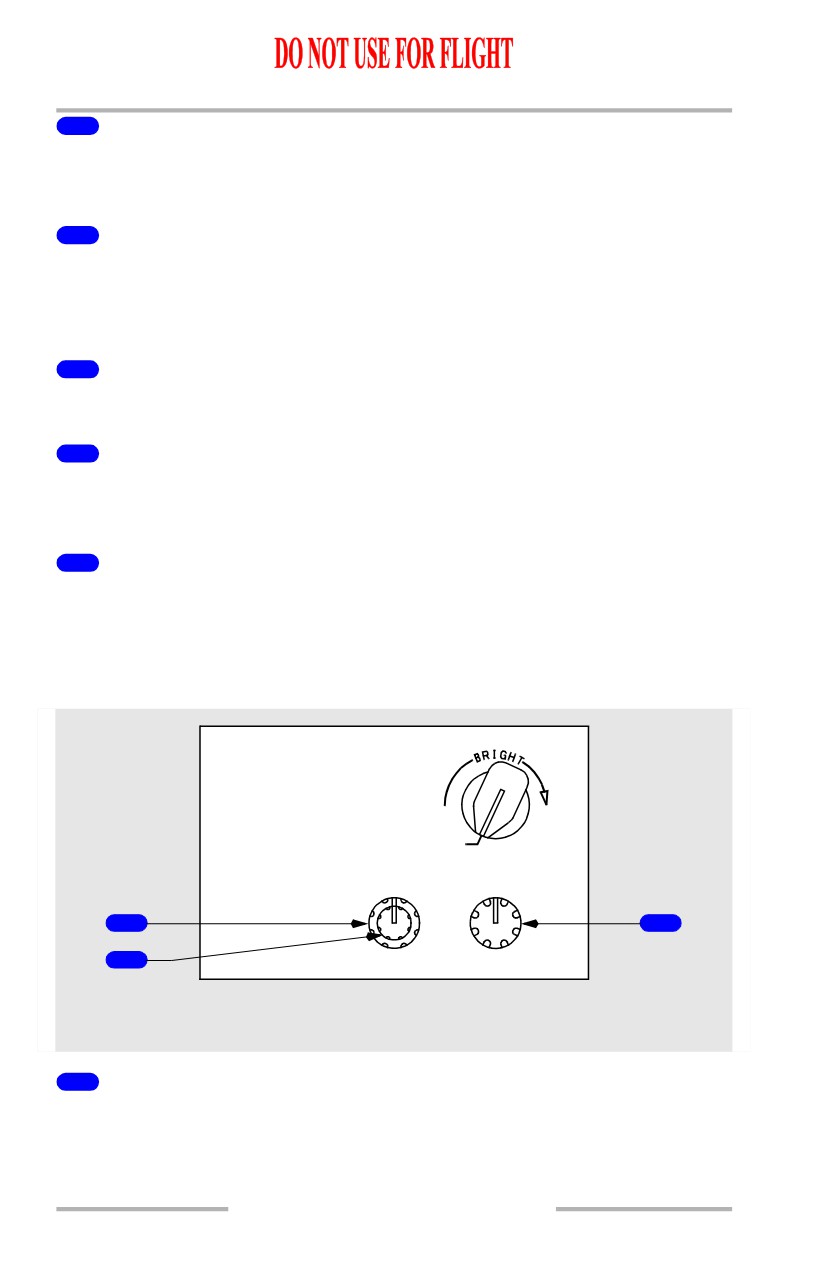
Display Brightness Controls
Captain Brightness Controls
MAIN PANEL
UPPER DU
BRT
4
OFF
OUTBD DU
INBD DU
LOWER DU
BRT
BRT
BRT
1
5
2
3
6
LEFT FORWARD PANEL
1
Outboard Display Unit Brightness (OUTBD DU BRT) Control
(rotary)
ROTATE - adjusts the brightness of the Captain outboard display unit.
10.16.7
Flight Instruments, Displays -
EFIS Instruments (PFD) -
Controls
Boeing 737 Operations Manual
2
Inboard Display Unit Brightness (INBD DU BRT) Control (outer)
(rotary)
ROTATE - adjusts the brightness of the Captain inboard display unit.
3
Inboard Display Unit Radar Brightness (INBD DU BRT) Control
(inner) (rotary)
ROTATE - adjusts weather radar and terrain display brightness on the Captain
inboard display unit.
4
Upper Display Unit Brightness (UPPER DU BRT) Control (rotary)
ROTATE - adjusts the brightness of the upper display unit.
5
Lower Display Unit Brightness (LOWER DU BRT) Control (outer)
(rotary)
ROTATE - adjusts the brightness of the lower display unit.
6
Lower Display Unit Brightness (LOWER DU BRT) Control (inner)
(rotary)
ROTATE - adjusts weather radar and terrain display brightness on the lower
display unit.
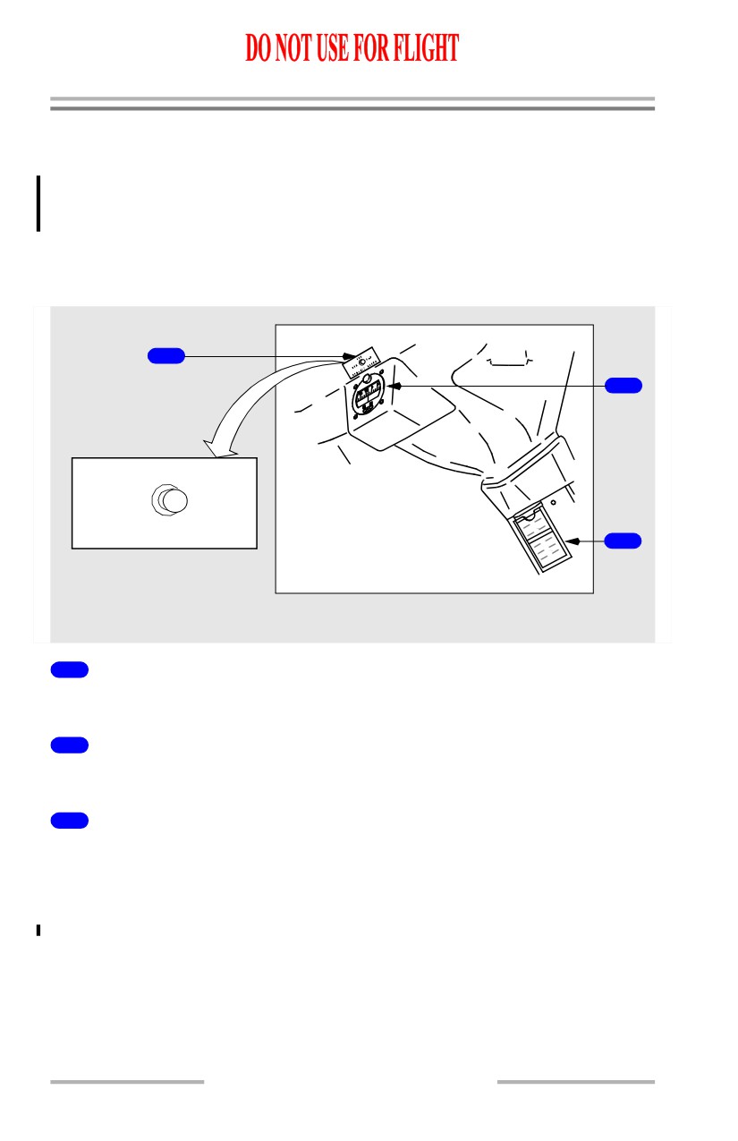
First Officer Brightness Controls
MAIN PANEL
OFF
INBD DU
OUTBD DU
BRT
BRT
1
3
2
RIGHT FORWARD PANEL
1
Inboard Display Unit Brightness (INBD DU BRT) Control (outer)
(rotary)
ROTATE - adjusts the brightness of the First Officer inboard display unit.
10.16.8
Flight Instruments, Displays -
EFIS Instruments (PFD) -
Controls
Boeing 737 Operations Manual
2
Inboard Display Unit Radar Brightness (INBD DU BRT) Control
(inner) (rotary)
ROTATE - adjusts weather radar and terrain display brightness on the First
Officer inboard display unit.
3
Outboard Display Unit Brightness (OUTBD DU BRT) Control
(rotary)
ROTATE - adjusts the brightness of the First Officer outboard display unit.
10.16.9
Flight Instruments, Displays -
EFIS Instruments (PFD) -
Controls
Boeing 737 Operations Manual
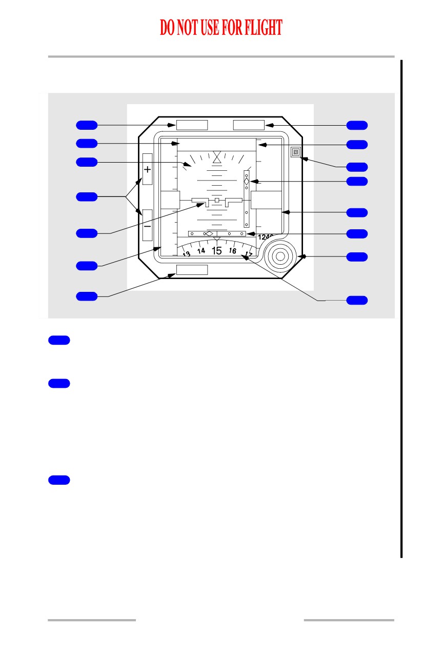
Standby Flight Instruments
The standby flight instruments include the:
• standby magnetic compass
• integrated standby flight
display
• standby radio magnetic
indicator.
Standby Magnetic Compass
3
1
OFF
DIM
BRT
COMPASS LIGHT
2
CENTER POST ABOVE GLARESHIELD
1
Standby Magnetic Compass
Displays magnetic heading.
2
Standby Magnetic Compass Correction Card
Provides appropriate heading corrections.
3
Compass Light Switch
OFF - compass light is extinguished.
BRT - sets compass light to full brightness.
DIM - sets compass light to low brightness.
10.16.10
Flight Instruments, Displays -
EFIS Instruments (PFD) -
Controls
Boeing 737 Operations Manual
Integrated Standby Flight Display
[Option - Sextant S231A120-1]
1
APP
HP/IN
8
2
APP
29.92 IN
9
13200
240
3
10
13000
220
10
11
4
1
40
20
12
7
0
20
12600
12
10
180
5
13
160
14
6
ATT
RST
BARO
7
15
CENTER INSTRUMENT PANEL
1
Approach (APP) Switch
Push - selects approach mode.
2
Approach Mode Annunciation
Indicates approach mode selected.
• Blank - no approach deviation data displayed
• APP - ILS localizer and glideslope deviation data displayed
• BCRS (Back course) - reverses sensing for localizer pointer during back
course approaches
3
Attitude Display
Displays airplane attitude.
• Indicates bank in reference to the bank scale
• Indicates the horizon relative to the airplane symbol
• Beyond 30 degrees pitch, large red arrowheads (V-shaped) indicate the
attitude has become excessive, and the direction to the horizon line.
10.16.11